

Philips MultiOne, MultiOne 2.6.5 User Manual
MultiOne
User manual
This manual has been updated for MultiOne version 2.6.5
© Philips Lighting B.V. 2014

User Manual Philips MultiOne
© Philips Lighting B.V. 2014 Page 2 / 81
1 Introduction
Today’s customer demands more flexibility and customization possibilities than
“physical configurations” can offer. With new Philips configurable devices with built-in
controls or separate controllers you can configure the luminaire’s behavior. You can
control output levels, or even pre-configure dynamic dimming on the client’s request;
either directly in the factory or during installation on location. All you need is ONE
intuitive tool that when plugged into a device can calibrate ALL the different
functions required by any lighting solution.
Creating the perfect lighting solution has been made very easy with Philips MultiOne.
With MultiOne, you can configure all features that are supported by a Philips device.
A feature typically belongs to one or two product groups (LED Indoor/Outdoor, HID
or FLUO), but this does not mean that every device from a product group does
support all features.
Philips MultiOne is supported by Windows XP + SP3, Windows 7, Windows 8 and 8.1
operating systems. It works only in combination with the Philips LCN8600 MultiOne
interface USB2DALI, with Philips LCN8650 MultiOne interface USB2ZigBee or with
Philips LCN9600 MultiOne interface SimpleSet.

User Manual Philips MultiOne
© Philips Lighting B.V. 2014 Page 3 / 81
2 Table of contents
1 Introduction ........................................................................................................................................2
3 System requirements ......................................................................................................................7
4 Downloading and installing MultiOne and the documentation package ...................8
5 Attention points ................................................................................................................................9
5.1 General .........................................................................................................................................9
5.2 DALI ...............................................................................................................................................9
6 The MultiOne interfaces ............................................................................................................. 10
6.1 DALI ............................................................................................................................................ 10
6.2 ZigBee ....................................................................................................................................... 11
6.3 SimpleSet ................................................................................................................................. 11
7 Starting MultiOne .......................................................................................................................... 12
7.1 Application mode selector ................................................................................................ 12
8 Selecting the interface ................................................................................................................. 14
9 Working with the Philips LCN8600 MultiOne interface USB2DALI ............................. 15
9.1 The main application window .......................................................................................... 15
9.2 Managing the DALI network ............................................................................................. 15
9.2.1 Identifying devices ....................................................................................................... 15
9.2.2 Selecting devices for communication ................................................................... 16
9.2.3 Managing user-defined groups .............................................................................. 17
9.2.4 Managing groups ......................................................................................................... 18
10 Working with the Philips LCN8650 MultiOne interface USB2ZigBee ......................... 20
10.1 The main application window ...................................................................................... 20
10.2 Connecting to a ZigBee network ................................................................................ 20
10.2.1 Identify devices ......................................................................................................... 20
10.2.2 Selecting devices for communication ............................................................... 21
10.3 Advanced commissioning .............................................................................................. 21
10.3.1 Identify devices ......................................................................................................... 21
10.3.2 Managing networks ................................................................................................. 22

User Manual Philips MultiOne
© Philips Lighting B.V. 2014 Page 4 / 81
10.3.3 Managing zones ....................................................................................................... 22
11 Working with the Philips LCN9600 MultiOne interface SimpleSet ............................. 25
11.1 The main application window ...................................................................................... 25
11.2 Scanning a SimpleSet device ........................................................................................ 25
11.2.1 Identifying devices ................................................................................................... 25
11.2.2 Auto read ..................................................................................................................... 27
11.3 Selecting devices for communication ....................................................................... 27
11.4 Starting communication ................................................................................................. 27
12 Working with MultiOne............................................................................................................... 28
12.1 Viewing device properties ............................................................................................. 28
12.2 Communicating with a device ...................................................................................... 28
12.3 Configuring device features .......................................................................................... 29
12.3.1 1-10V min dim level ................................................................................................ 31
12.3.2 ActiLume General ..................................................................................................... 31
12.3.3 ActiLume Mode ......................................................................................................... 32
12.3.4 ActiLume Scene ......................................................................................................... 32
12.3.5 ActiLume Wireless General ................................................................................... 33
12.3.6 ActiLume Wireless Mode ....................................................................................... 34
12.3.7 Active Cooling ........................................................................................................... 34
12.3.8 Adjustable Light Output ........................................................................................ 35
12.3.9 Adjustable Output Current ................................................................................... 36
12.3.10 Adjustable Startup Time ........................................................................................ 36
12.3.11 AmpDim ....................................................................................................................... 37
12.3.12 Constant Light Output ............................................................................................ 38
12.3.13 Corridor Mode ........................................................................................................... 40
12.3.14 Dimming Interface ................................................................................................... 41
12.3.15 Dynadimmer ............................................................................................................... 42
12.3.16 DC Emergency ........................................................................................................... 44
12.3.17 End Of Life indication .............................................................................................. 46
12.3.18 Energy Meter .............................................................................................................. 46

User Manual Philips MultiOne
© Philips Lighting B.V. 2014 Page 5 / 81
12.3.19 Lamp Burn-in ............................................................................................................. 47
12.3.20 Lamp Selection .......................................................................................................... 47
12.3.21 Light Source Operating Hours ............................................................................. 48
12.3.22 LineSwitch ................................................................................................................... 48
12.3.23 LumiStep ...................................................................................................................... 49
12.3.24 Min Dim Level ............................................................................................................ 50
12.3.25 Module Temperature Protection ........................................................................ 51
12.3.26 Quick Lamp Start ...................................................................................................... 52
12.3.27 Touch and Dim .......................................................................................................... 52
12.4 Using the features summary ......................................................................................... 53
12.5 Saving and opening a feature configuration file ................................................... 53
12.6 Configuring a single device........................................................................................... 55
12.7 Configuring multiple DALI devices (simultaneously) ........................................... 55
12.8 Configuring multiple DALI devices (consecutively) .............................................. 56
12.8.1 MultiOne Basic .......................................................................................................... 56
12.8.2 MultiOne (full version) ............................................................................................ 56
12.9 Offline feature configuration preparation ............................................................... 57
12.10 Accessing diagnostics ..................................................................................................... 57
12.11 Sending DALI commands .............................................................................................. 61
12.12 Querying devices .............................................................................................................. 62
12.13 Working with DALI command scripts ........................................................................ 63
12.14 The logging window ........................................................................................................ 65
12.15 Setting preferences .......................................................................................................... 67
12.16 Manually selecting the USB2DALI interface ............................................................ 68
12.17 Enabling/Disabling the power supply of the USB2DALI interface .................. 70
12.18 Supported features .......................................................................................................... 70
12.19 Device-specific technical descriptions ...................................................................... 71
12.20 Error handling .................................................................................................................... 71
12.20.1 Reporting and correction of errors/warnings when reading from a
feature configuration file ........................................................................................................... 71

User Manual Philips MultiOne
© Philips Lighting B.V. 2014 Page 6 / 81
12.20.2 Reporting of errors when reading from a device ......................................... 71
12.20.3 Reporting of errors when entering incorrect values in a feature ............ 71
12.21 Troubleshooting ................................................................................................................ 72
13 Keyboard shortcuts ....................................................................................................................... 74
14 Software Update ............................................................................................................................ 75
15 Copyright .......................................................................................................................................... 77
16 Disclaimer ......................................................................................................................................... 78
17 Limitations of damages ............................................................................................................... 79
18 List of tables .................................................................................................................................... 80
19 Index .................................................................................................................................................. 81

User Manual Philips MultiOne
© Philips Lighting B.V. 2014 Page 7 / 81
3 System requirements
The minimum system requirements for using MultiOne are:
- PC or laptop with Microsoft Windows XP SP3, Windows 7, Windows 8 or 8.1
- USB 2.0 ports:
o Two free USB 2.0 ports for use with USB2DALI interface
o One free USB 2.0 port for use with USB2ZigBee interface
o One free USB 2.0 port for use with SimpleSet interface
- At least 30 MB of free disk space
- Microsoft .NET Framework 3.5 SP1 (download here for offline installation)

User Manual Philips MultiOne
© Philips Lighting B.V. 2014 Page 8 / 81
4 Downloading and installing MultiOne and the
documentation package
A zip-file can be downloaded from www.philips.com/MultiOne. This zip-file contains
the following files:
Philips MultiOne.exe (executable/installer)
Philips MultiOne Workflow.exe (executable/installer)
GettingStarted.pdf (document)
UserManual.pdf (document)
RELEASE_NOTES.txt (document)
The MultiOne installation file is the installer for the full version of MultiOne. This
document applies to this version of the software.
The MultiOne Workflow installation file is the version of MultiOne which is meant to
be used in a production environment.
To install the software, launch the installer for the desired version and follow the
instructions on your screen.
The installation wizard will guide you through the process of installing the software
and will ask you where the software needs to be installed. At the end, it will give you
the option to immediately start MultiOne.

User Manual Philips MultiOne
© Philips Lighting B.V. 2014 Page 9 / 81
5 Attention points
5.1 General
Before starting MultiOne, make sure that the correct interface (USB2DALI,
USB2ZigBee or SimpleSet) has been connected to your computer.
When upgrading the Windows Operating System, make sure the connection settings
are correct when using MultiOne again.
5.2 DALI
Lighting applications with DALI devices can be seriously affected by the
presence/absence of the DALI short address. Make sure the DALI short address is as
you expect, after finishing working with MultiOne.
User Manual Philips MultiOne
© Philips Lighting B.V. 2014 Page 10 / 81
6 The MultiOne interfaces
6.1 DALI
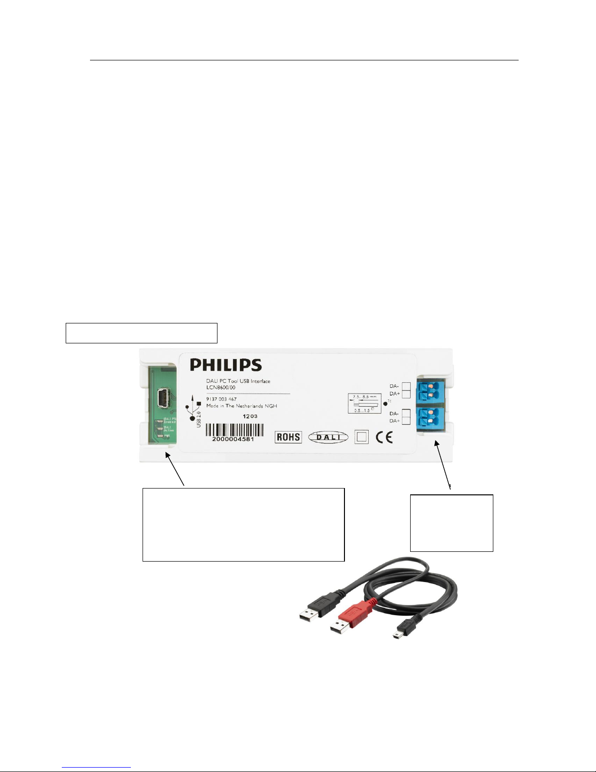
The Philips LCN8600 MultiOne interface USB2DALI (USB2DALI interface) is the
interface between the PC and the DALI devices. It has a mini- USB input connector
and two parallel DALI output connectors. The USB2DALI interface status is indicated
by three LED’s located near the mini-USB connector.
The USB2DALI interface is supplied with a USB cable that can supply the DALI
network with up to 220mA. It is advised to only use the supplied cable, in order to
assure correct functioning of the USB2DALI interface.
Safety: Class II, double insulated
DALI open circuit voltage (when power supply enabled): 15V
mini-USB input connector
Status LEDs:
DALI power supply enabled
DALI active
Power
Double DALI
output
connector
User Manual Philips MultiOne
© Philips Lighting B.V. 2014 Page 11 / 81
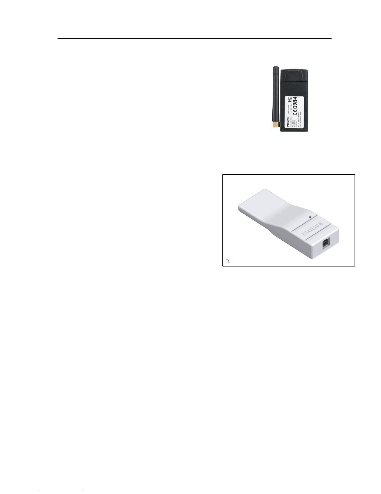
6.2 ZigBee
The Philips LCN8650 MultiOne interface USB2ZigBee
(USB2ZigBee interface) is an USB dongle which interfaces
between the PC and the ZigBee devices.
6.3 SimpleSet
The Philips LCN9600 MultiOne interface SimpleSet
(SimpleSet interface) is an USB device which interfaces between the PC and the
SimpleSet devices.
User Manual Philips MultiOne
© Philips Lighting B.V. 2014 Page 12 / 81
7 Starting MultiOne
Before starting MultiOne, make sure that the correct interface (USB2DALI,
USB2ZigBee or SimpleSet) has been connected to your computer.
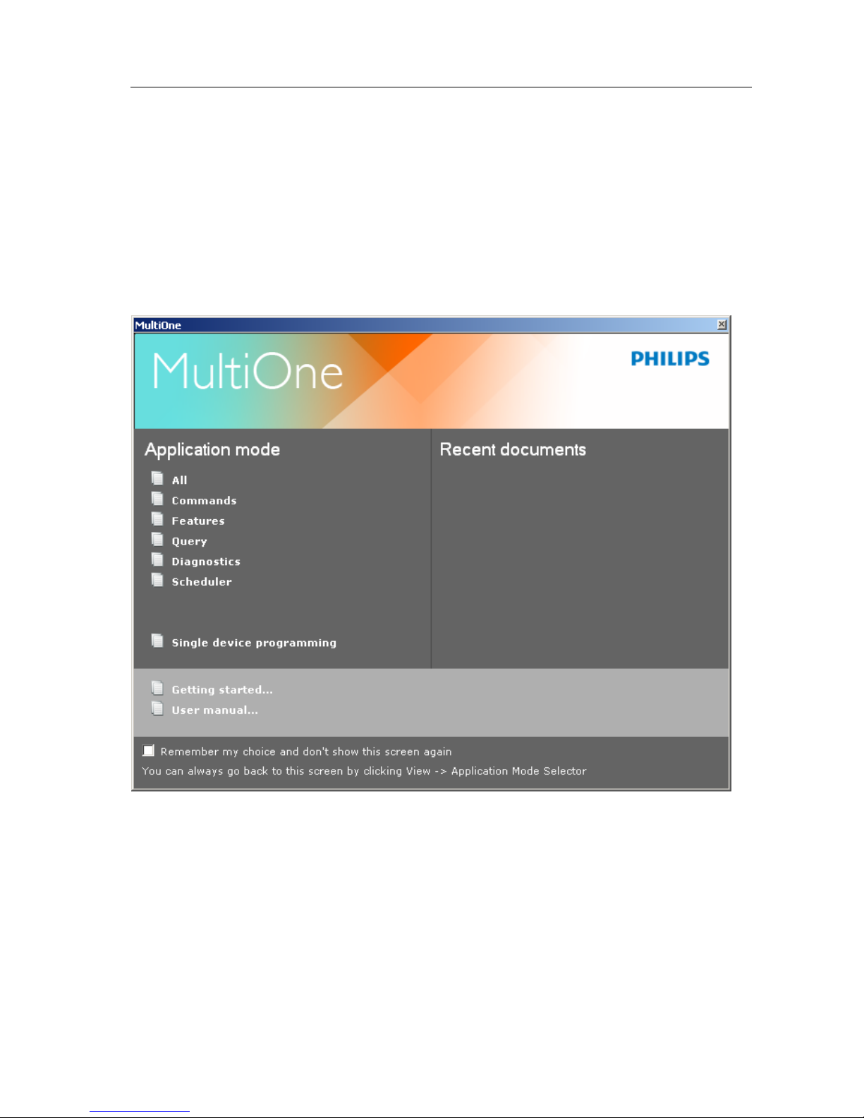
7.1 Application mode selector
When starting MultiOne, the first window that appears is the Application Mode
Selector. Here, you can choose an application mode, based on the tasks you would
like to perform. The application window also has links to the documentation.
One of the modes is Single device programming. This mode simplifies some parts
of the device configuration workflow when only one device has been connected.
Single device programming is discussed in detail in chapter 12.6.
If you know that you will mostly perform the same tasks in the future, you can select
Remember my choice and then click the appropriate application mode. MultiOne
will record your choice and The Application Mode Selector will not appear again the
next time MultiOne is started.

User Manual Philips MultiOne
© Philips Lighting B.V. 2014 Page 13 / 81
You can always go back to the Application Mode Selector by selecting View
Application Mode Selector from the main application window.
User Manual Philips MultiOne
© Philips Lighting B.V. 2014 Page 14 / 81
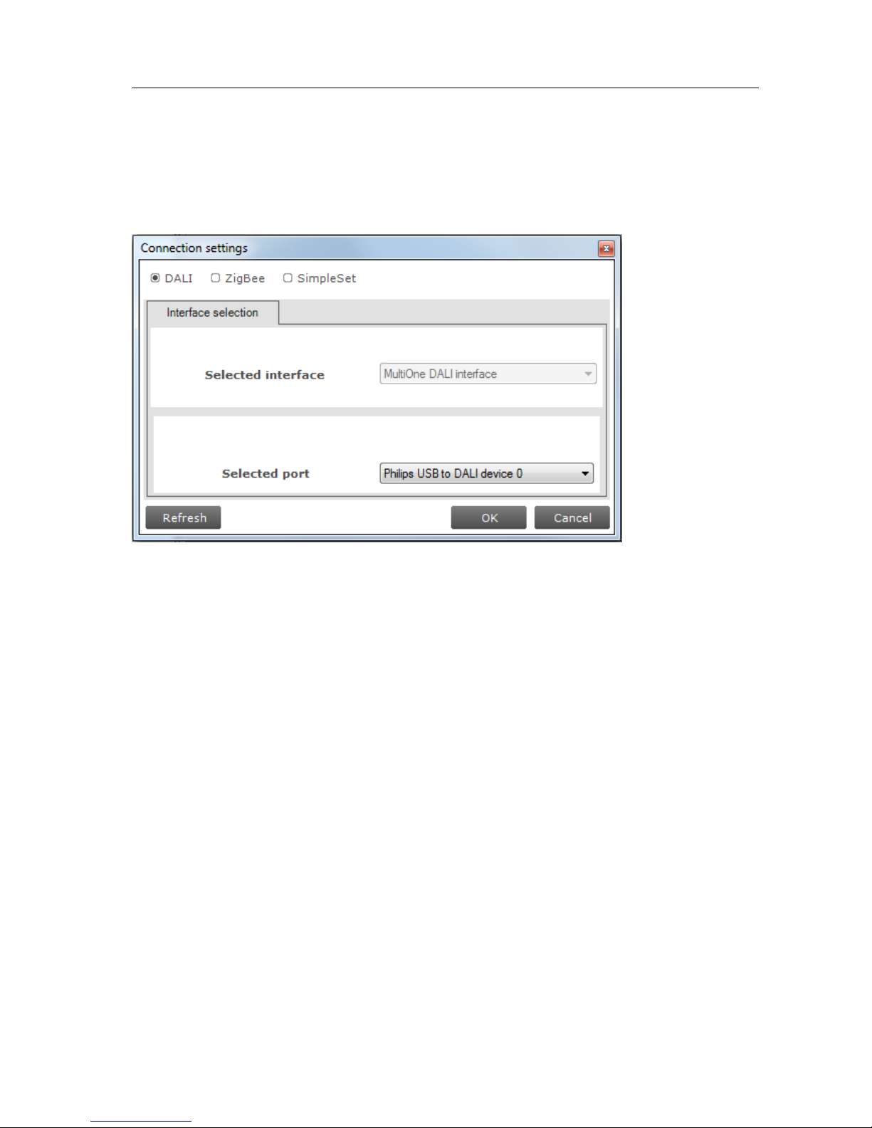
8 Selecting the interface
After the Application Mode Selector you must select the interface (USB2DALI,
USB2ZigBee or SimpleSet) to work with. First select the protocol: DALI, ZigBee or
SimpleSet, when needed also indicate the selected interface and port.
This protocol can always be changed later, by going to the Tools Connection
settings.
User Manual Philips MultiOne
© Philips Lighting B.V. 2014 Page 15 / 81
9 Working with the Philips LCN8600 MultiOne interface
USB2DALI
Before using MultiOne with the USB2DALI interface make sure that all devices that
need to be commissioned are connected to the mains and the DALI network. Finally
the DALI network must be connected to one of the DALI connectors of the USB2DALI
interface.
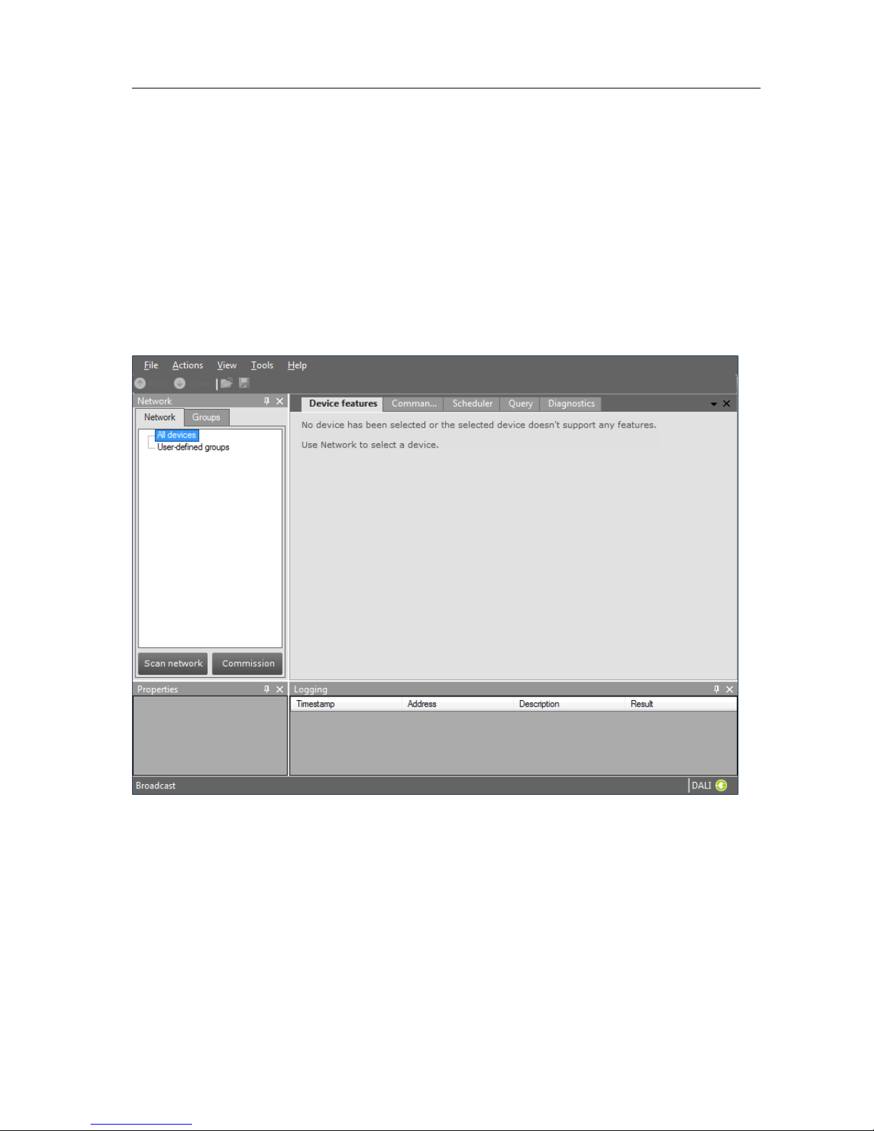
9.1 The main application window
If in the Application Mode Selector screen All is selected as application mode, the
program will start as follows:
A more thorough explanation on how to communicate with devices can be found in
chapters 12.2, 12.11, 12.13, 12.12 and 12.3 of this manual.
9.2 Managing the DALI network
The Network panel is used to manage the connected DALI network. A number of
tasks can be performed in the Network, each of which is detailed below.
9.2.1 Identifying devices
User Manual Philips MultiOne
© Philips Lighting B.V. 2014 Page 16 / 81
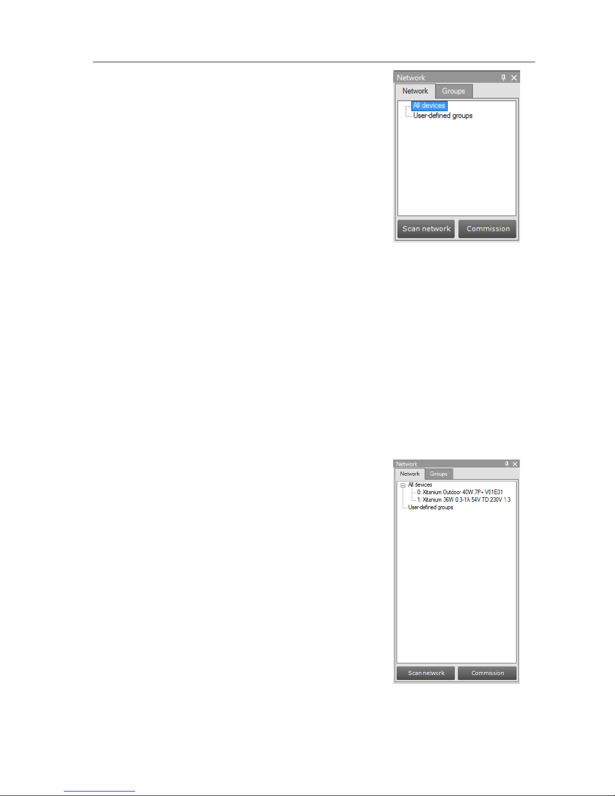
When starting MultiOne, the DALI devices connected to
the USB2DALI interface are not automatically identified.
There are two methods for identifying the devices with
corresponding buttons in the Network on the left-hand
side of the application window: Scan network and
Commission.
Scan network
In order to communicate with a device, the device needs
to have a short address. The Scan network button scans
all devices for their short addresses. This procedure does
not change any short address or other property of the
connected devices, provided they already have a short address. Devices without a
short address are being assigned a unique one. When two or more devices have the
same short address, a warning is displayed.
Commissioning
All devices are given a new unique short address, starting at 0. Be aware that existing
short addresses are erased and new short addresses are re-assigned to all connected
devices. This procedure ensures that all devices have a short address and that there
are no duplicate short addresses.
After commissioning or scanning the network, the list of identified devices is shown in
the Network.
9.2.2 Selecting devices for communication
After having commissioned or scanned the network, the
Network shows all devices present in the DALI network.
By clicking a device you will make that particular device
the active one, meaning that all commands will be sent to
this device only, and will be ignored by all other devices.
Besides selecting a single device for communication, it is
also possible to communicate with groups of devices. The
options are:
All devices in the network. Select All devices. All
commands will now be sent as broadcast
commands. Note that unidentified but connected
DALI devices will also respond to commands.
All user-defined groups. Select User-defined
groups. All commands will now be sent to devices
that belong to a user-defined group. User defined
groups are explained in the section 9.2.3.
User Manual Philips MultiOne
© Philips Lighting B.V. 2014 Page 17 / 81
A specific user-defined group. Expand User-defined groups and select the
desired user-defined group. All commands will now be sent to devices that
belong to this specific user-defined group.
9.2.3 Managing user-defined groups
Using the Network, devices can temporarily be grouped into user-defined groups.
The purpose of user-defined groups is that they facilitate easy clustering so that a
number of devices can be addressed simultaneously.
The user-defined groups are lost when MultiOne is closed.
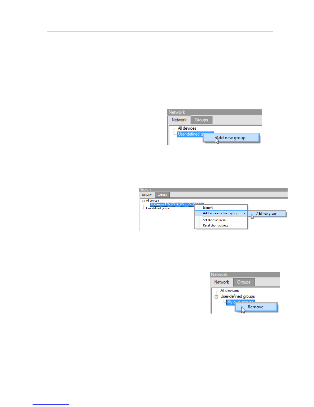
A new user-defined group can be created by
right-clicking User-defined groups and
selecting Add new group. Alternatively
choose Actions Add user-defined
group. A new group is created with a default
name, but it can be renamed by clicking it once. To add a device to a user-defined
group, right-click the device, select Add to custom group and select one of the
available user-defined groups. Alternatively, the device can be dragged onto the
desired user-defined group to add it to that group.
To immediately add a device to a
new user-defined group, rightclick a device and select Add to
user-defined group and select
Add new group. The user-
defined group will be created and
the selected device will be added to the newly created user-defined group.
To remove a device from a user-defined group, right-click the device in the group
and select Remove.
To remove an entire user-defined group (including its
devices), right-click the group and select Remove.
The number of devices in a user-defined group is limited to
64.
User Manual Philips MultiOne
© Philips Lighting B.V. 2014 Page 18 / 81
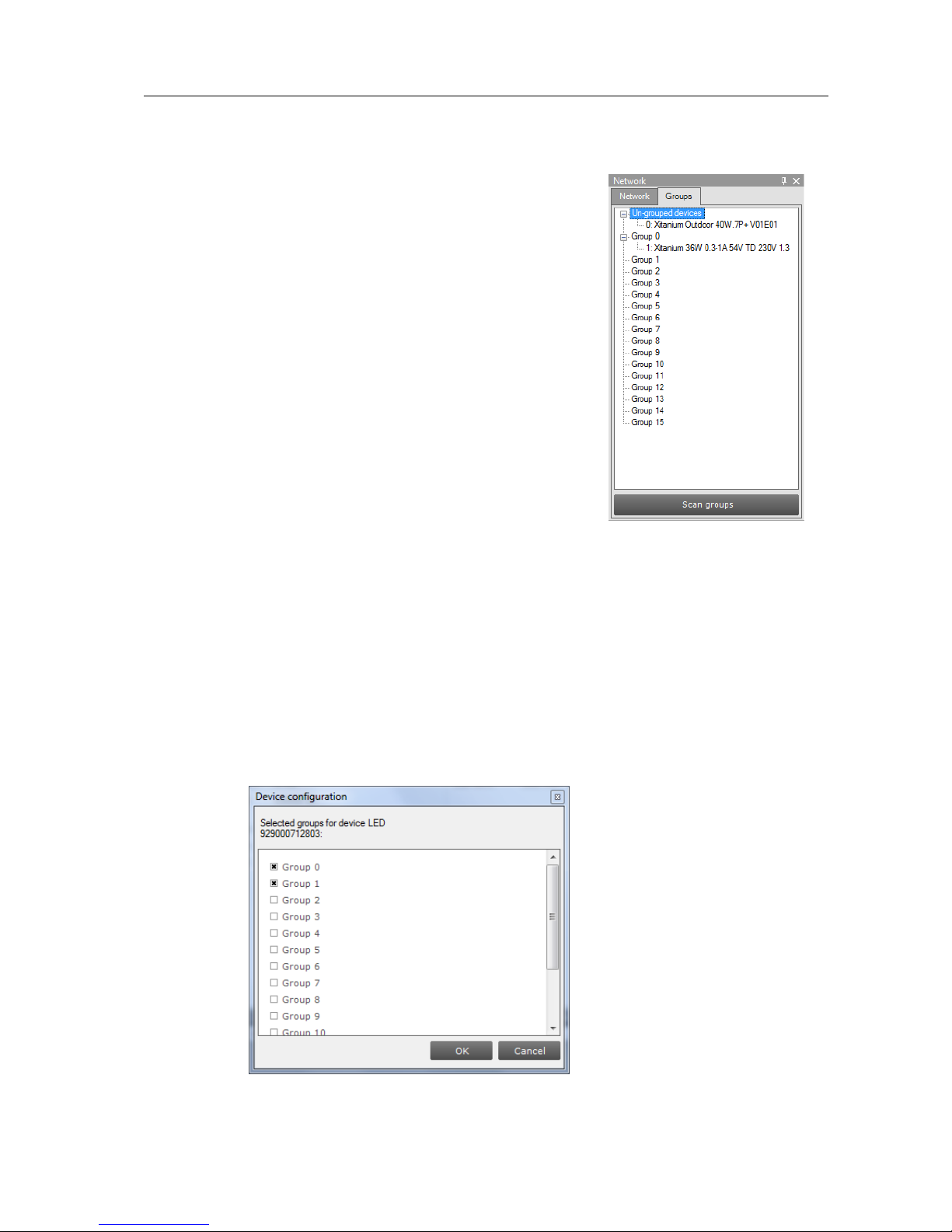
9.2.4 Managing groups
Once all the devices in the DALI network are
commissioned, i.e. have a unique short address, it is
possible to work with DALI groups.
Select the Groups tab and press Scan groups. After
having scanned the network for groups, the Groups tab
shows all the DALI groups and the found devices for every
group.
DALI groups are much more comprehensive than userdefined groups. The important difference is that with DALI
grouping information is stored in the devices themselves.
Therefore, DALI grouping is more permanent than userdefined grouping.
By clicking on a device you will make that particular device the active one, meaning
that all actions will be performed on this device only, and will be ignored by all other
devices.
The options are:
With a right-click on an un-grouped device you can:
o Identify the device
o Add to, add the device to one group
o Configure…, add device to multiple groups
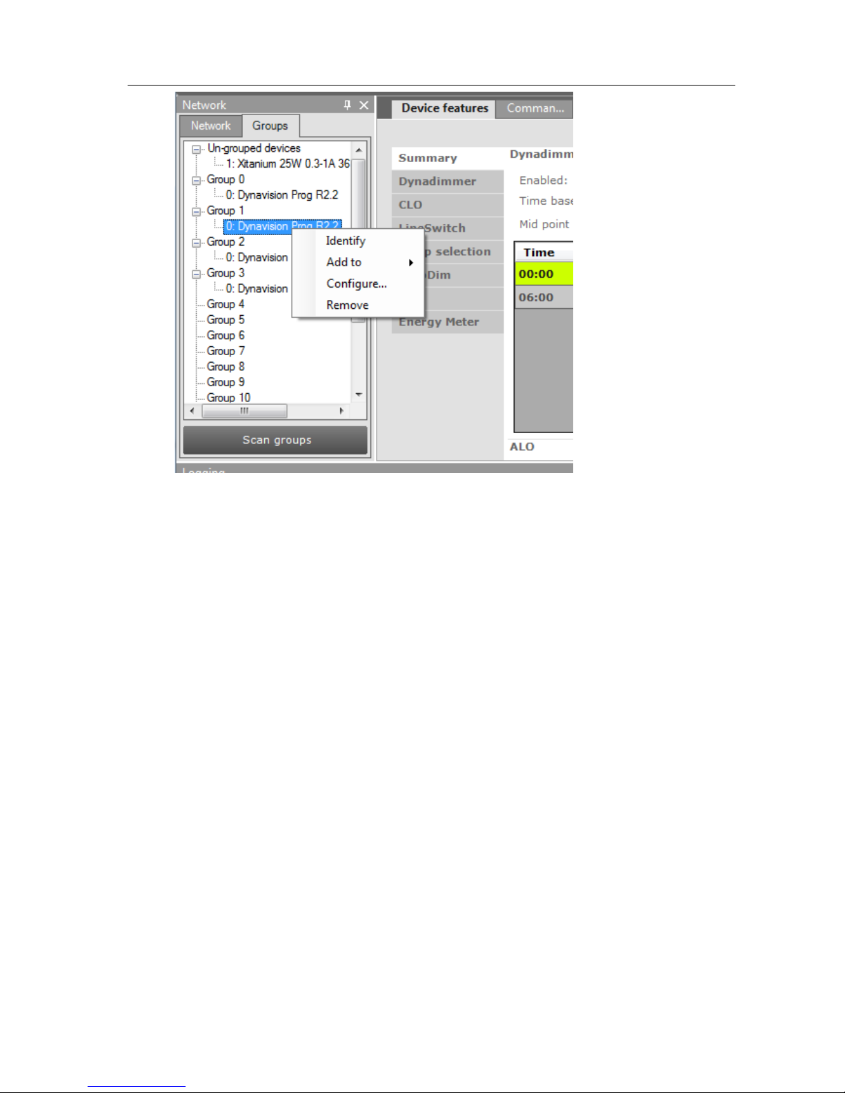
With a right-click on a device in a group you can:
User Manual Philips MultiOne
© Philips Lighting B.V. 2014 Page 19 / 81
o Identify the device
o Add to, add the device to one other group
o Configure…, add/remove device to/from multiple groups
o Remove, remove device from current group
Besides selecting a single device for communication, it is also possible to
communicate with a group of devices.
The options are:
With a right-click on a group you can:
o Identify the devices in the group
o Configure…, add/remove multiple devices to/from the group
o Clear group, remove the devices from the group
The number of devices in a DALI group is limited to 64.

User Manual Philips MultiOne
© Philips Lighting B.V. 2014 Page 20 / 81
10 Working with the Philips LCN8650 MultiOne interface
USB2ZigBee
10.1 The main application window
If in the Application Mode Selector screen All is selected as application mode, the
program will start as follows:
10.2 Connecting to a ZigBee network
The Network panel is used to manage a connected ZigBee network. A
number of tasks can be performed in the Network panel, each of which
is detailed below.
10.2.1 Identify devices
The ZigBee devices and networks in the area of the USB2ZigBee
interface are not automatically known. To find devices and networks in
the area press Connect to network: MultiOne scans for an open
network in the area and connects to the network. After connecting has
finished, the network and the found devices are shown in the Network
panel.
User Manual Philips MultiOne
© Philips Lighting B.V. 2014 Page 21 / 81
10.2.2 Selecting devices for communication
After having connected to the network, the Network panel shows all devices and the
network to which MultiOne is connected. By clicking on a device or network you will
make that particular device or network the active one, meaning that all actions will be
performed on this device or network only, and will be ignored by all other devices or
networks.
With a right click on a device you can
Identify the device
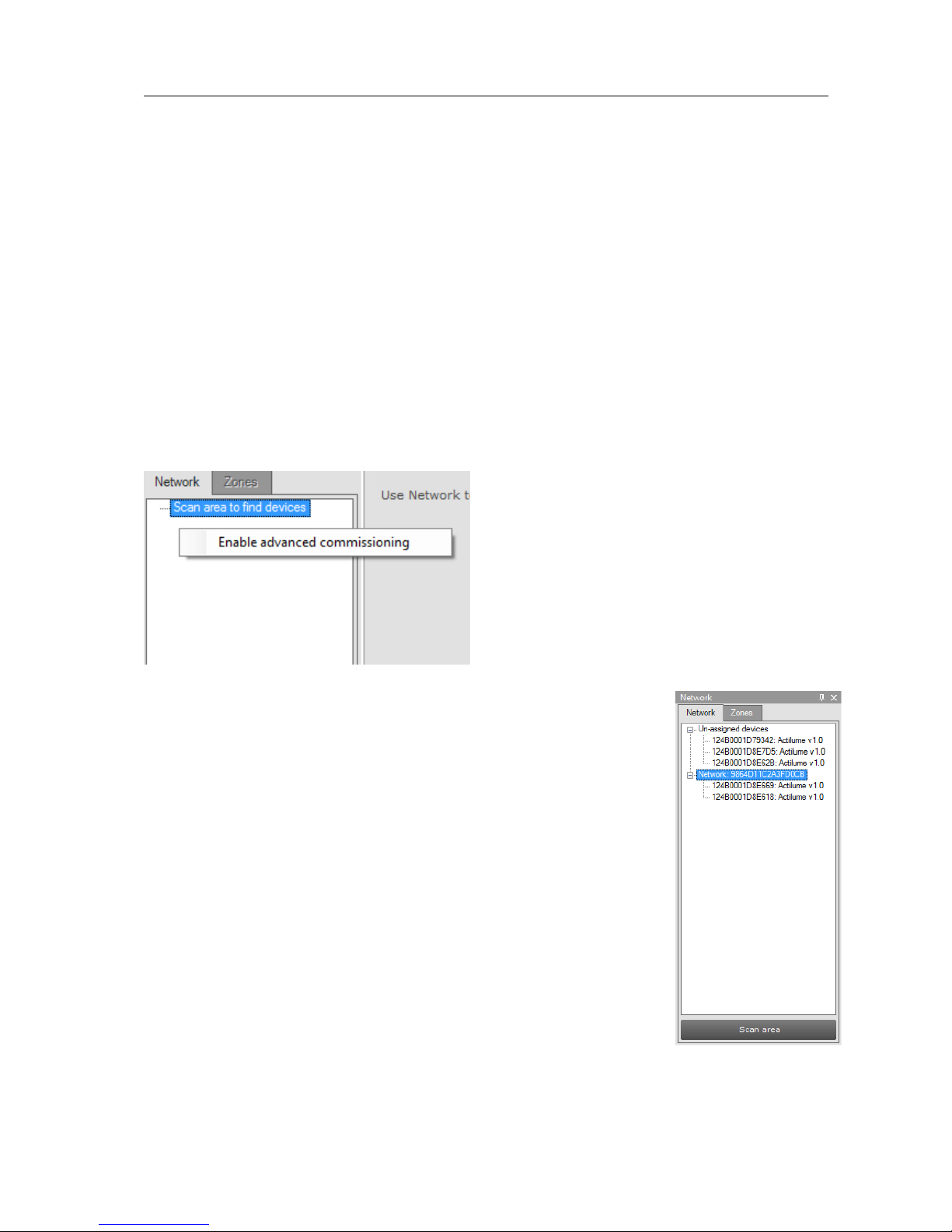
10.3 Advanced commissioning
To commission a ZigBee network, right click the Network panel and choose Enable
advanced commissioning.
The Network panel switches to a different view making it possible
to manage ZigBee networks.
10.3.1 Identify devices
Press Scan area to scan for all the devices and network in the area
of the USB2ZigBee interface. After scan has finished the devices
and networks in range of the interface are shown in the Network
panel.
User Manual Philips MultiOne
© Philips Lighting B.V. 2014 Page 22 / 81
10.3.2 Managing networks
The options are:
With a right-click on an unassigned device you can:
o Add to, move the device to an existing network or move the device to a
new network
With a right-click on a device in a network you can:
o Add to, move the device to an existing network or move the device to a
new network
o Reset, from network, the device will become unassigned. If the network
becomes empty, the network will be removed
With a right-click on a network you can:
o Query network, to find all devices in the network, including the devices
that are out of range of the USB2ZigBee interface
o Open network, to add more devices
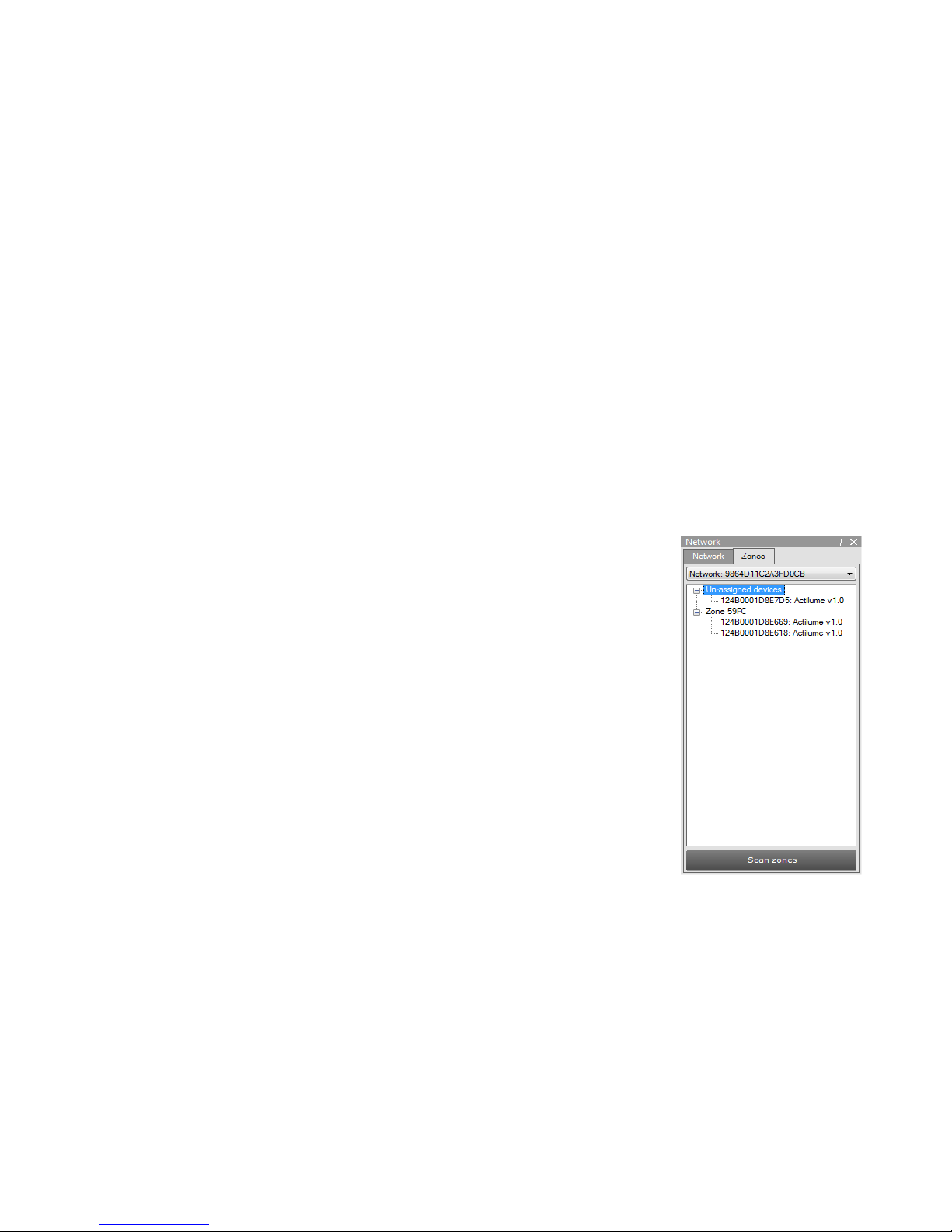
10.3.3 Managing zones
Once you have scanned the area and found devices and networks
in range, it is possible to scan a specific network for zones. Select
the Zones tab, select the Network and press Scan zones. After
having scanned the network, the Zones tab shows the found
devices and zones within the specified network.
By clicking on a device or zone you will make that particular device
or zone the active one, meaning that all actions will be performed
on this device or zone only, and will be ignored by all other devices.
With a right-click on an unassigned device you can:
o Identify the device
o Add to, move the device to an existing or new zone
With a right-click on a device in a zone you can:
o Identify the device
o Add to, move the device to an another or new zone
o Configure…, move the device to another zone
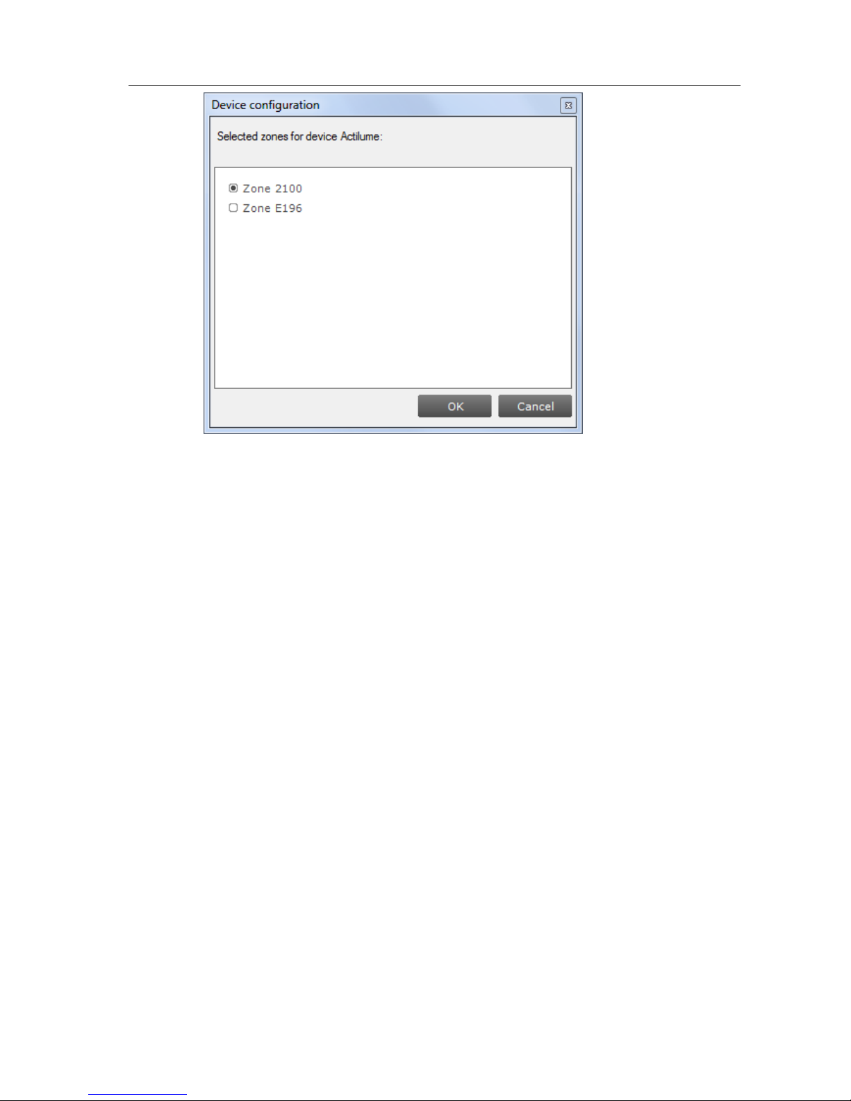
User Manual Philips MultiOne
© Philips Lighting B.V. 2014 Page 23 / 81
o Remove, the device will become unassigned. If the zone becomes
empty, the zone will be removed
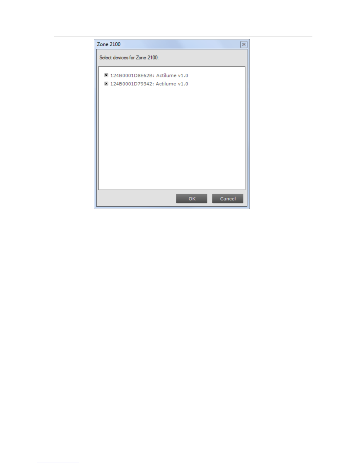
With a right-click on a zone you can:
o Identify the zone
o Configure…, add/remove multiple devices to/from the zone. If other
zones become empty, they will be removed
User Manual Philips MultiOne
© Philips Lighting B.V. 2014 Page 24 / 81
o Remove zone, the zone will be removed and the devices will become
unassigned

User Manual Philips MultiOne
© Philips Lighting B.V. 2014 Page 25 / 81
11 Working with the Philips LCN9600 MultiOne interface
SimpleSet
11.1 The main application window
If in the Application Mode Selector screen All is selected as application mode, the
program will start as follows:
11.2 Scanning a SimpleSet device
The Network panel is used to manage the scanned SimpleSet
devices. A number of tasks can be performed in the Network panel,
each of which is detailed below.
11.2.1 Identifying devices
The SimpleSet device near the SimpleSet interface is not
automatically known by MultiOne. To get the device press Scan for
device: a pop-up will appear indicating the device must touch the
interface. Touch and hold the device close to the SimpleSet interface
 Loading...