

Page 1

MultiOne
User manual
This manual has been updated for MultiOne version 2.6.5
© Philips Lighting B.V. 2014
Page 2

User Manual Philips MultiOne
© Philips Lighting B.V. 2014 Page 2 / 81
1 Introduction
Today’s customer demands more flexibility and customization possibilities than
“physical configurations” can offer. With new Philips configurable devices with built-in
controls or separate controllers you can configure the luminaire’s behavior. You can
control output levels, or even pre-configure dynamic dimming on the client’s request;
either directly in the factory or during installation on location. All you need is ONE
intuitive tool that when plugged into a device can calibrate ALL the different
functions required by any lighting solution.
Creating the perfect lighting solution has been made very easy with Philips MultiOne.
With MultiOne, you can configure all features that are supported by a Philips device.
A feature typically belongs to one or two product groups (LED Indoor/Outdoor, HID
or FLUO), but this does not mean that every device from a product group does
support all features.
Philips MultiOne is supported by Windows XP + SP3, Windows 7, Windows 8 and 8.1
operating systems. It works only in combination with the Philips LCN8600 MultiOne
interface USB2DALI, with Philips LCN8650 MultiOne interface USB2ZigBee or with
Philips LCN9600 MultiOne interface SimpleSet.
Page 3

User Manual Philips MultiOne
© Philips Lighting B.V. 2014 Page 3 / 81
2 Table of contents
1 Introduction ........................................................................................................................................2
3 System requirements ......................................................................................................................7
4 Downloading and installing MultiOne and the documentation package ...................8
5 Attention points ................................................................................................................................9
5.1 General .........................................................................................................................................9
5.2 DALI ...............................................................................................................................................9
6 The MultiOne interfaces ............................................................................................................. 10
6.1 DALI ............................................................................................................................................ 10
6.2 ZigBee ....................................................................................................................................... 11
6.3 SimpleSet ................................................................................................................................. 11
7 Starting MultiOne .......................................................................................................................... 12
7.1 Application mode selector ................................................................................................ 12
8 Selecting the interface ................................................................................................................. 14
9 Working with the Philips LCN8600 MultiOne interface USB2DALI ............................. 15
9.1 The main application window .......................................................................................... 15
9.2 Managing the DALI network ............................................................................................. 15
9.2.1 Identifying devices ....................................................................................................... 15
9.2.2 Selecting devices for communication ................................................................... 16
9.2.3 Managing user-defined groups .............................................................................. 17
9.2.4 Managing groups ......................................................................................................... 18
10 Working with the Philips LCN8650 MultiOne interface USB2ZigBee ......................... 20
10.1 The main application window ...................................................................................... 20
10.2 Connecting to a ZigBee network ................................................................................ 20
10.2.1 Identify devices ......................................................................................................... 20
10.2.2 Selecting devices for communication ............................................................... 21
10.3 Advanced commissioning .............................................................................................. 21
10.3.1 Identify devices ......................................................................................................... 21
10.3.2 Managing networks ................................................................................................. 22
Page 4

User Manual Philips MultiOne
© Philips Lighting B.V. 2014 Page 4 / 81
10.3.3 Managing zones ....................................................................................................... 22
11 Working with the Philips LCN9600 MultiOne interface SimpleSet ............................. 25
11.1 The main application window ...................................................................................... 25
11.2 Scanning a SimpleSet device ........................................................................................ 25
11.2.1 Identifying devices ................................................................................................... 25
11.2.2 Auto read ..................................................................................................................... 27
11.3 Selecting devices for communication ....................................................................... 27
11.4 Starting communication ................................................................................................. 27
12 Working with MultiOne............................................................................................................... 28
12.1 Viewing device properties ............................................................................................. 28
12.2 Communicating with a device ...................................................................................... 28
12.3 Configuring device features .......................................................................................... 29
12.3.1 1-10V min dim level ................................................................................................ 31
12.3.2 ActiLume General ..................................................................................................... 31
12.3.3 ActiLume Mode ......................................................................................................... 32
12.3.4 ActiLume Scene ......................................................................................................... 32
12.3.5 ActiLume Wireless General ................................................................................... 33
12.3.6 ActiLume Wireless Mode ....................................................................................... 34
12.3.7 Active Cooling ........................................................................................................... 34
12.3.8 Adjustable Light Output ........................................................................................ 35
12.3.9 Adjustable Output Current ................................................................................... 36
12.3.10 Adjustable Startup Time ........................................................................................ 36
12.3.11 AmpDim ....................................................................................................................... 37
12.3.12 Constant Light Output ............................................................................................ 38
12.3.13 Corridor Mode ........................................................................................................... 40
12.3.14 Dimming Interface ................................................................................................... 41
12.3.15 Dynadimmer ............................................................................................................... 42
12.3.16 DC Emergency ........................................................................................................... 44
12.3.17 End Of Life indication .............................................................................................. 46
12.3.18 Energy Meter .............................................................................................................. 46
Page 5

User Manual Philips MultiOne
© Philips Lighting B.V. 2014 Page 5 / 81
12.3.19 Lamp Burn-in ............................................................................................................. 47
12.3.20 Lamp Selection .......................................................................................................... 47
12.3.21 Light Source Operating Hours ............................................................................. 48
12.3.22 LineSwitch ................................................................................................................... 48
12.3.23 LumiStep ...................................................................................................................... 49
12.3.24 Min Dim Level ............................................................................................................ 50
12.3.25 Module Temperature Protection ........................................................................ 51
12.3.26 Quick Lamp Start ...................................................................................................... 52
12.3.27 Touch and Dim .......................................................................................................... 52
12.4 Using the features summary ......................................................................................... 53
12.5 Saving and opening a feature configuration file ................................................... 53
12.6 Configuring a single device........................................................................................... 55
12.7 Configuring multiple DALI devices (simultaneously) ........................................... 55
12.8 Configuring multiple DALI devices (consecutively) .............................................. 56
12.8.1 MultiOne Basic .......................................................................................................... 56
12.8.2 MultiOne (full version) ............................................................................................ 56
12.9 Offline feature configuration preparation ............................................................... 57
12.10 Accessing diagnostics ..................................................................................................... 57
12.11 Sending DALI commands .............................................................................................. 61
12.12 Querying devices .............................................................................................................. 62
12.13 Working with DALI command scripts ........................................................................ 63
12.14 The logging window ........................................................................................................ 65
12.15 Setting preferences .......................................................................................................... 67
12.16 Manually selecting the USB2DALI interface ............................................................ 68
12.17 Enabling/Disabling the power supply of the USB2DALI interface .................. 70
12.18 Supported features .......................................................................................................... 70
12.19 Device-specific technical descriptions ...................................................................... 71
12.20 Error handling .................................................................................................................... 71
12.20.1 Reporting and correction of errors/warnings when reading from a
feature configuration file ........................................................................................................... 71
Page 6

User Manual Philips MultiOne
© Philips Lighting B.V. 2014 Page 6 / 81
12.20.2 Reporting of errors when reading from a device ......................................... 71
12.20.3 Reporting of errors when entering incorrect values in a feature ............ 71
12.21 Troubleshooting ................................................................................................................ 72
13 Keyboard shortcuts ....................................................................................................................... 74
14 Software Update ............................................................................................................................ 75
15 Copyright .......................................................................................................................................... 77
16 Disclaimer ......................................................................................................................................... 78
17 Limitations of damages ............................................................................................................... 79
18 List of tables .................................................................................................................................... 80
19 Index .................................................................................................................................................. 81
Page 7

User Manual Philips MultiOne
© Philips Lighting B.V. 2014 Page 7 / 81
3 System requirements
The minimum system requirements for using MultiOne are:
- PC or laptop with Microsoft Windows XP SP3, Windows 7, Windows 8 or 8.1
- USB 2.0 ports:
o Two free USB 2.0 ports for use with USB2DALI interface
o One free USB 2.0 port for use with USB2ZigBee interface
o One free USB 2.0 port for use with SimpleSet interface
- At least 30 MB of free disk space
- Microsoft .NET Framework 3.5 SP1 (download here for offline installation)
Page 8

User Manual Philips MultiOne
© Philips Lighting B.V. 2014 Page 8 / 81
4 Downloading and installing MultiOne and the
documentation package
A zip-file can be downloaded from www.philips.com/MultiOne. This zip-file contains
the following files:
Philips MultiOne.exe (executable/installer)
Philips MultiOne Workflow.exe (executable/installer)
GettingStarted.pdf (document)
UserManual.pdf (document)
RELEASE_NOTES.txt (document)
The MultiOne installation file is the installer for the full version of MultiOne. This
document applies to this version of the software.
The MultiOne Workflow installation file is the version of MultiOne which is meant to
be used in a production environment.
To install the software, launch the installer for the desired version and follow the
instructions on your screen.
The installation wizard will guide you through the process of installing the software
and will ask you where the software needs to be installed. At the end, it will give you
the option to immediately start MultiOne.
Page 9

User Manual Philips MultiOne
© Philips Lighting B.V. 2014 Page 9 / 81
5 Attention points
5.1 General
Before starting MultiOne, make sure that the correct interface (USB2DALI,
USB2ZigBee or SimpleSet) has been connected to your computer.
When upgrading the Windows Operating System, make sure the connection settings
are correct when using MultiOne again.
5.2 DALI
Lighting applications with DALI devices can be seriously affected by the
presence/absence of the DALI short address. Make sure the DALI short address is as
you expect, after finishing working with MultiOne.
Page 10
User Manual Philips MultiOne
© Philips Lighting B.V. 2014 Page 10 / 81
6 The MultiOne interfaces
6.1 DALI
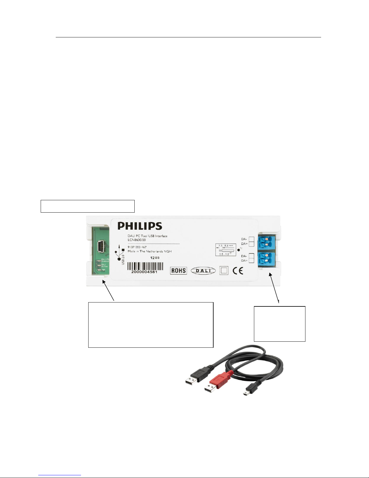
The Philips LCN8600 MultiOne interface USB2DALI (USB2DALI interface) is the
interface between the PC and the DALI devices. It has a mini- USB input connector
and two parallel DALI output connectors. The USB2DALI interface status is indicated
by three LED’s located near the mini-USB connector.
The USB2DALI interface is supplied with a USB cable that can supply the DALI
network with up to 220mA. It is advised to only use the supplied cable, in order to
assure correct functioning of the USB2DALI interface.
Safety: Class II, double insulated
DALI open circuit voltage (when power supply enabled): 15V
mini-USB input connector
Status LEDs:
DALI power supply enabled
DALI active
Power
Double DALI
output
connector
Page 11
User Manual Philips MultiOne
© Philips Lighting B.V. 2014 Page 11 / 81
6.2 ZigBee
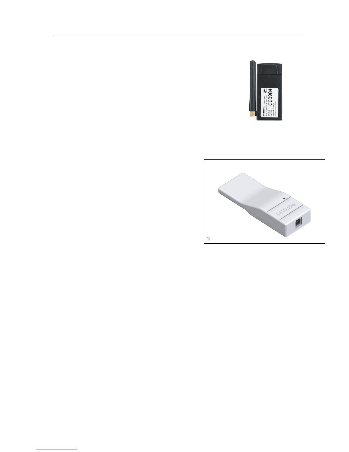
The Philips LCN8650 MultiOne interface USB2ZigBee
(USB2ZigBee interface) is an USB dongle which interfaces
between the PC and the ZigBee devices.
6.3 SimpleSet
The Philips LCN9600 MultiOne interface SimpleSet
(SimpleSet interface) is an USB device which interfaces between the PC and the
SimpleSet devices.
Page 12
User Manual Philips MultiOne
© Philips Lighting B.V. 2014 Page 12 / 81
7 Starting MultiOne
Before starting MultiOne, make sure that the correct interface (USB2DALI,
USB2ZigBee or SimpleSet) has been connected to your computer.
7.1 Application mode selector
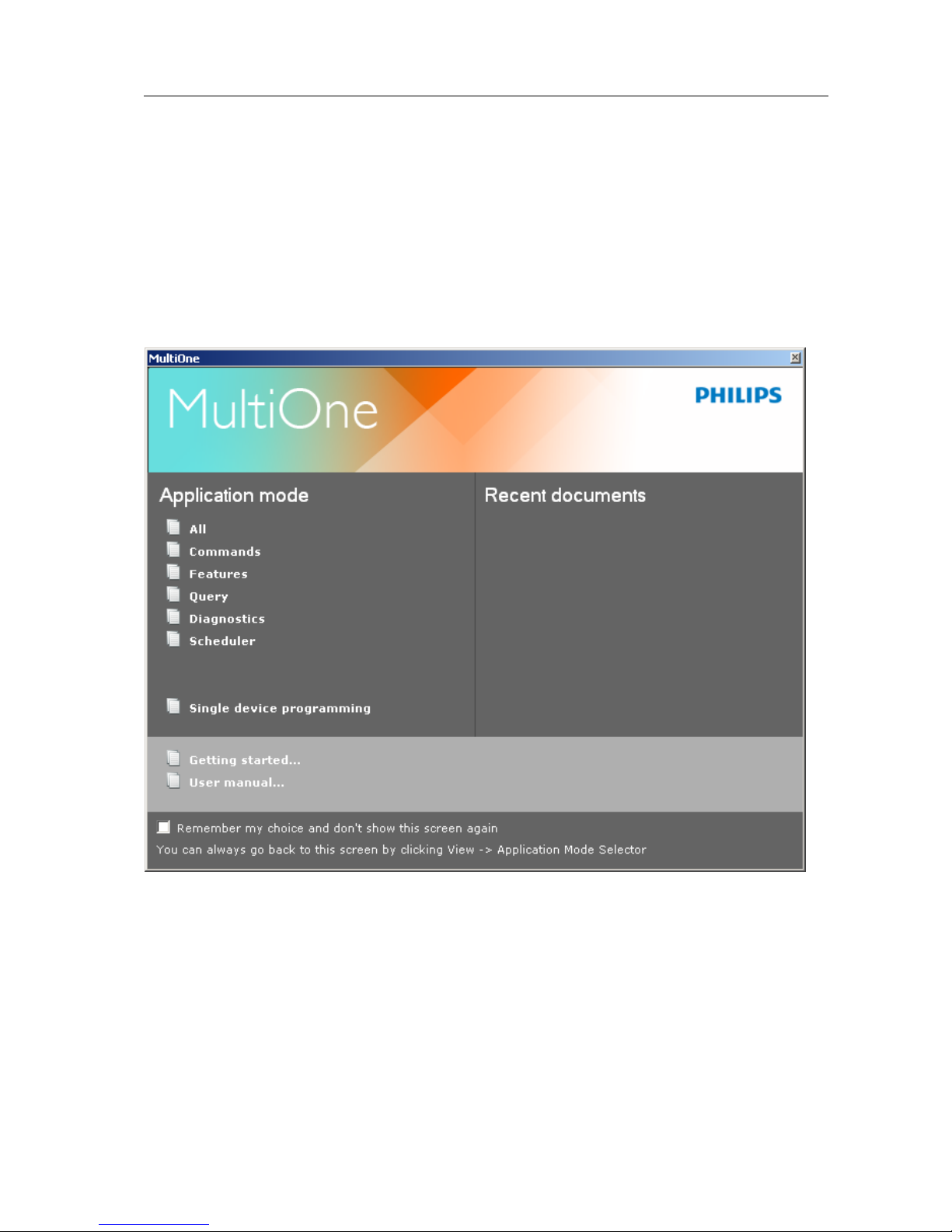
When starting MultiOne, the first window that appears is the Application Mode
Selector. Here, you can choose an application mode, based on the tasks you would
like to perform. The application window also has links to the documentation.
One of the modes is Single device programming. This mode simplifies some parts
of the device configuration workflow when only one device has been connected.
Single device programming is discussed in detail in chapter 12.6.
If you know that you will mostly perform the same tasks in the future, you can select
Remember my choice and then click the appropriate application mode. MultiOne
will record your choice and The Application Mode Selector will not appear again the
next time MultiOne is started.
Page 13

User Manual Philips MultiOne
© Philips Lighting B.V. 2014 Page 13 / 81
You can always go back to the Application Mode Selector by selecting View
Application Mode Selector from the main application window.
Page 14
User Manual Philips MultiOne
© Philips Lighting B.V. 2014 Page 14 / 81
8 Selecting the interface
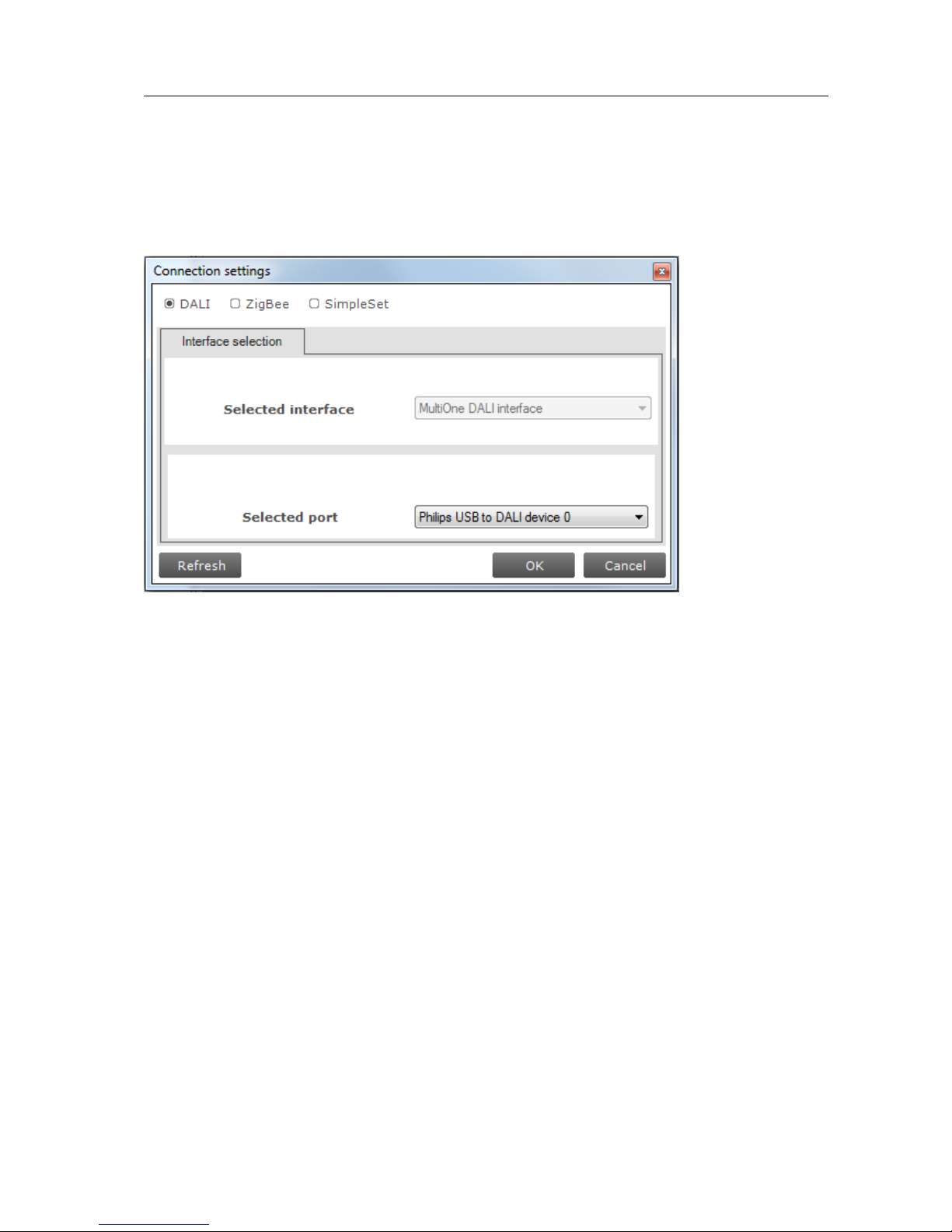
After the Application Mode Selector you must select the interface (USB2DALI,
USB2ZigBee or SimpleSet) to work with. First select the protocol: DALI, ZigBee or
SimpleSet, when needed also indicate the selected interface and port.
This protocol can always be changed later, by going to the Tools Connection
settings.
Page 15
User Manual Philips MultiOne
© Philips Lighting B.V. 2014 Page 15 / 81
9 Working with the Philips LCN8600 MultiOne interface
USB2DALI
Before using MultiOne with the USB2DALI interface make sure that all devices that
need to be commissioned are connected to the mains and the DALI network. Finally
the DALI network must be connected to one of the DALI connectors of the USB2DALI
interface.
9.1 The main application window
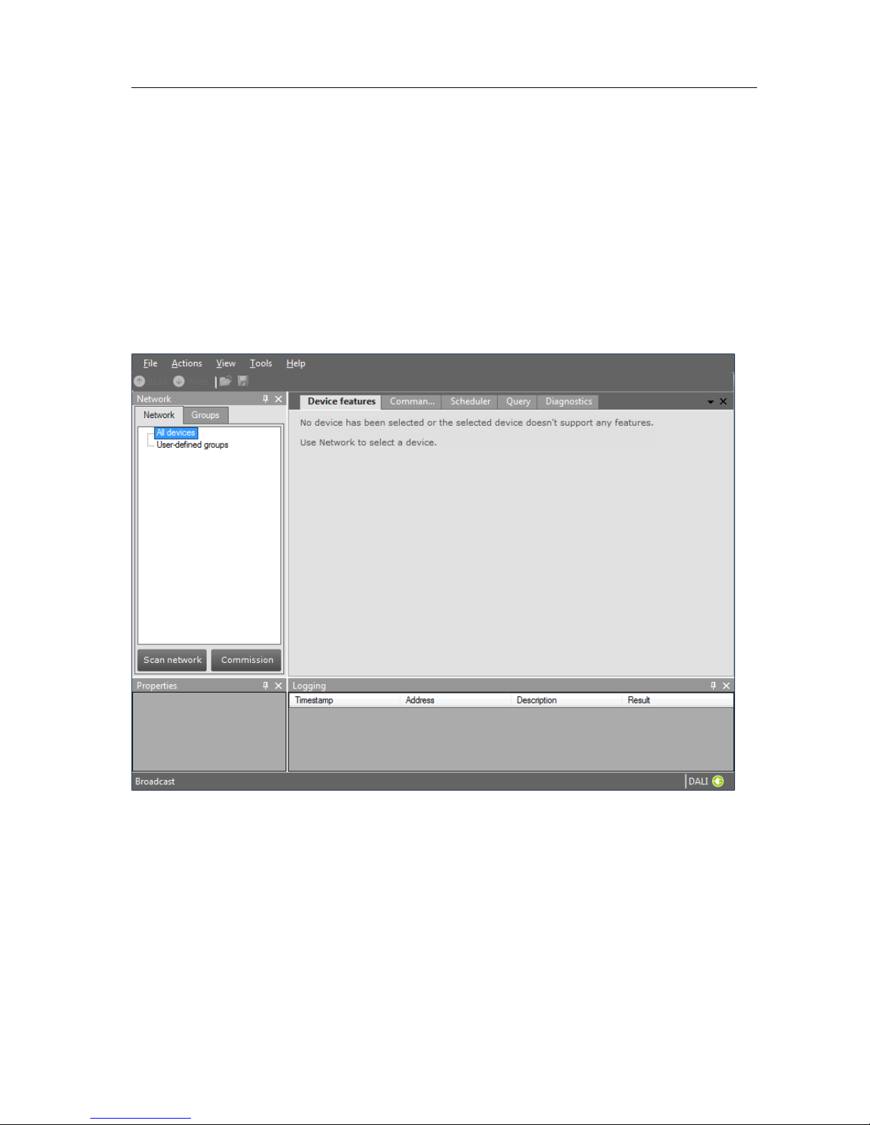
If in the Application Mode Selector screen All is selected as application mode, the
program will start as follows:
A more thorough explanation on how to communicate with devices can be found in
chapters 12.2, 12.11, 12.13, 12.12 and 12.3 of this manual.
9.2 Managing the DALI network
The Network panel is used to manage the connected DALI network. A number of
tasks can be performed in the Network, each of which is detailed below.
9.2.1 Identifying devices
Page 16
User Manual Philips MultiOne
© Philips Lighting B.V. 2014 Page 16 / 81
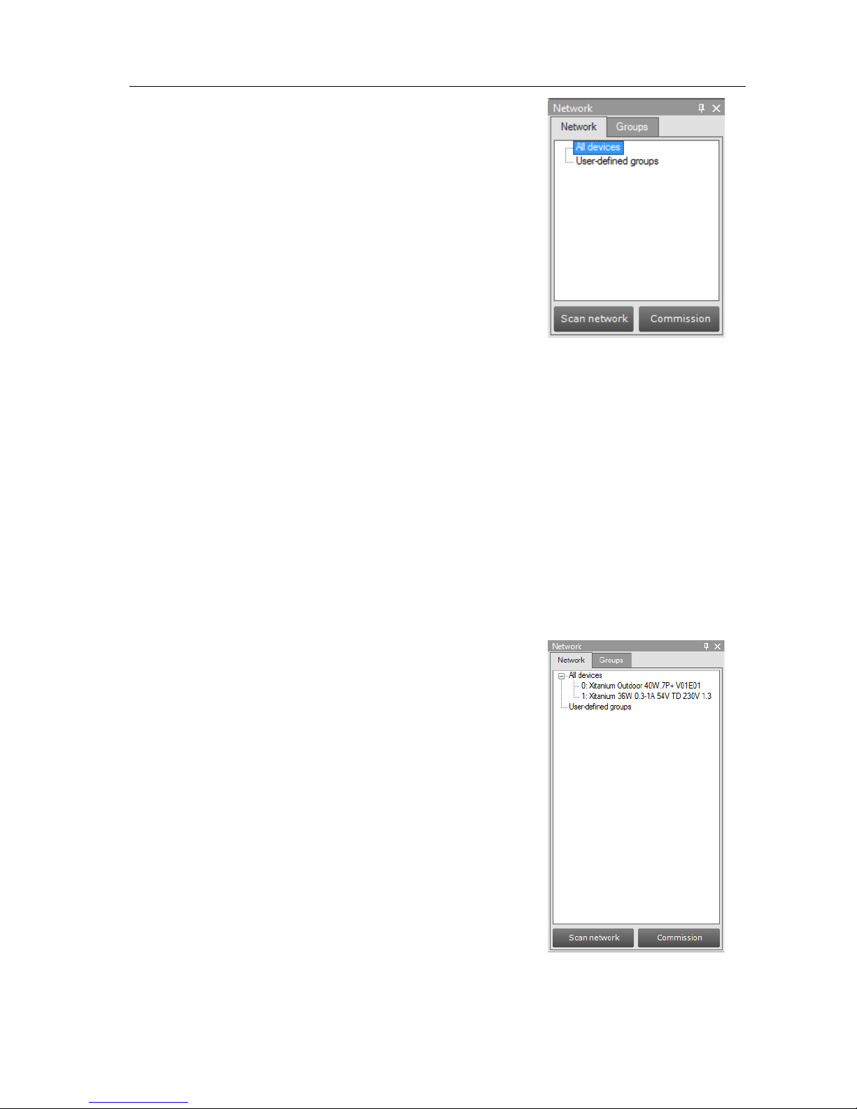
When starting MultiOne, the DALI devices connected to
the USB2DALI interface are not automatically identified.
There are two methods for identifying the devices with
corresponding buttons in the Network on the left-hand
side of the application window: Scan network and
Commission.
Scan network
In order to communicate with a device, the device needs
to have a short address. The Scan network button scans
all devices for their short addresses. This procedure does
not change any short address or other property of the
connected devices, provided they already have a short address. Devices without a
short address are being assigned a unique one. When two or more devices have the
same short address, a warning is displayed.
Commissioning
All devices are given a new unique short address, starting at 0. Be aware that existing
short addresses are erased and new short addresses are re-assigned to all connected
devices. This procedure ensures that all devices have a short address and that there
are no duplicate short addresses.
After commissioning or scanning the network, the list of identified devices is shown in
the Network.
9.2.2 Selecting devices for communication
After having commissioned or scanned the network, the
Network shows all devices present in the DALI network.
By clicking a device you will make that particular device
the active one, meaning that all commands will be sent to
this device only, and will be ignored by all other devices.
Besides selecting a single device for communication, it is
also possible to communicate with groups of devices. The
options are:
All devices in the network. Select All devices. All
commands will now be sent as broadcast
commands. Note that unidentified but connected
DALI devices will also respond to commands.
All user-defined groups. Select User-defined
groups. All commands will now be sent to devices
that belong to a user-defined group. User defined
groups are explained in the section 9.2.3.
Page 17
User Manual Philips MultiOne
© Philips Lighting B.V. 2014 Page 17 / 81
A specific user-defined group. Expand User-defined groups and select the
desired user-defined group. All commands will now be sent to devices that
belong to this specific user-defined group.
9.2.3 Managing user-defined groups
Using the Network, devices can temporarily be grouped into user-defined groups.
The purpose of user-defined groups is that they facilitate easy clustering so that a
number of devices can be addressed simultaneously.
The user-defined groups are lost when MultiOne is closed.
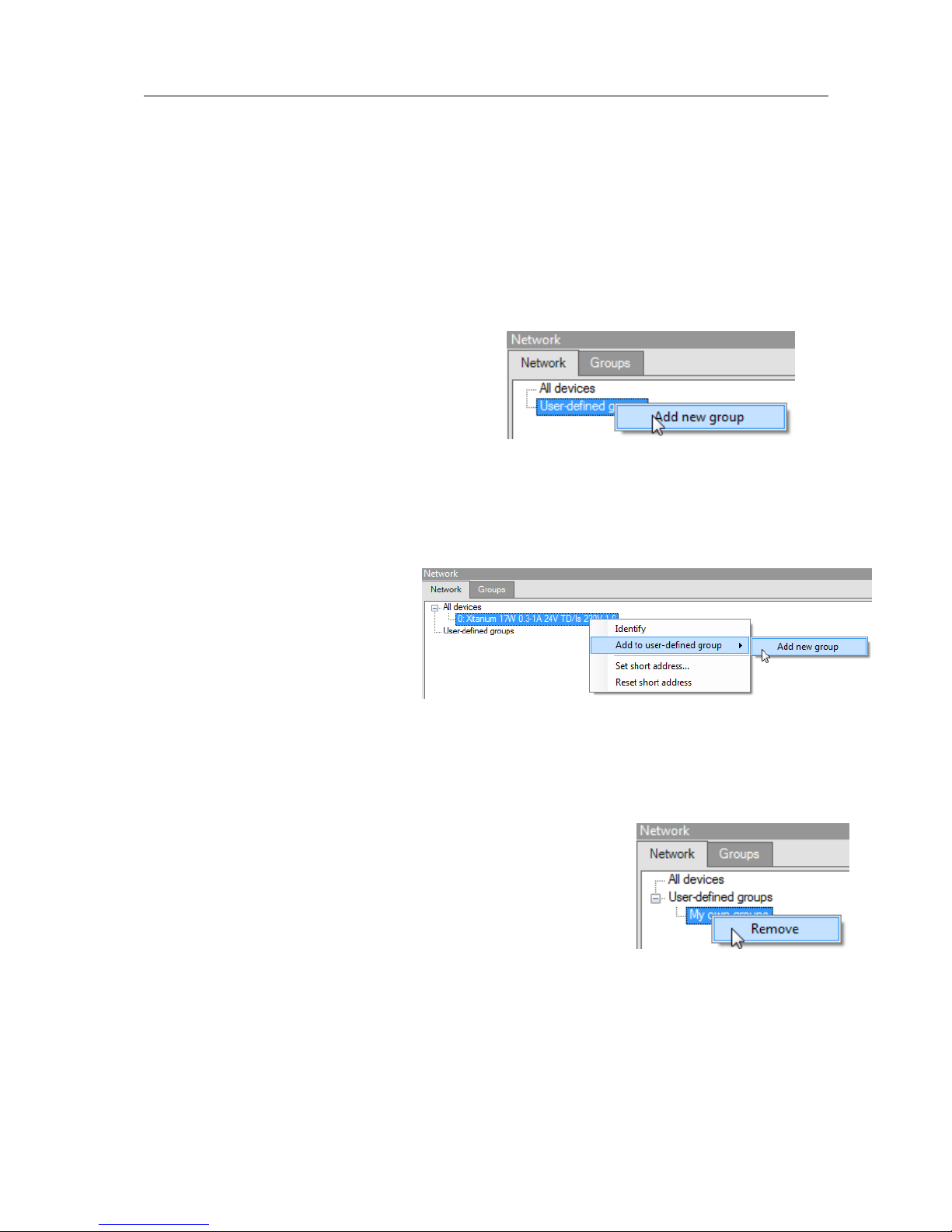
A new user-defined group can be created by
right-clicking User-defined groups and
selecting Add new group. Alternatively
choose Actions Add user-defined
group. A new group is created with a default
name, but it can be renamed by clicking it once. To add a device to a user-defined
group, right-click the device, select Add to custom group and select one of the
available user-defined groups. Alternatively, the device can be dragged onto the
desired user-defined group to add it to that group.
To immediately add a device to a
new user-defined group, rightclick a device and select Add to
user-defined group and select
Add new group. The user-
defined group will be created and
the selected device will be added to the newly created user-defined group.
To remove a device from a user-defined group, right-click the device in the group
and select Remove.
To remove an entire user-defined group (including its
devices), right-click the group and select Remove.
The number of devices in a user-defined group is limited to
64.
Page 18
User Manual Philips MultiOne
© Philips Lighting B.V. 2014 Page 18 / 81
9.2.4 Managing groups
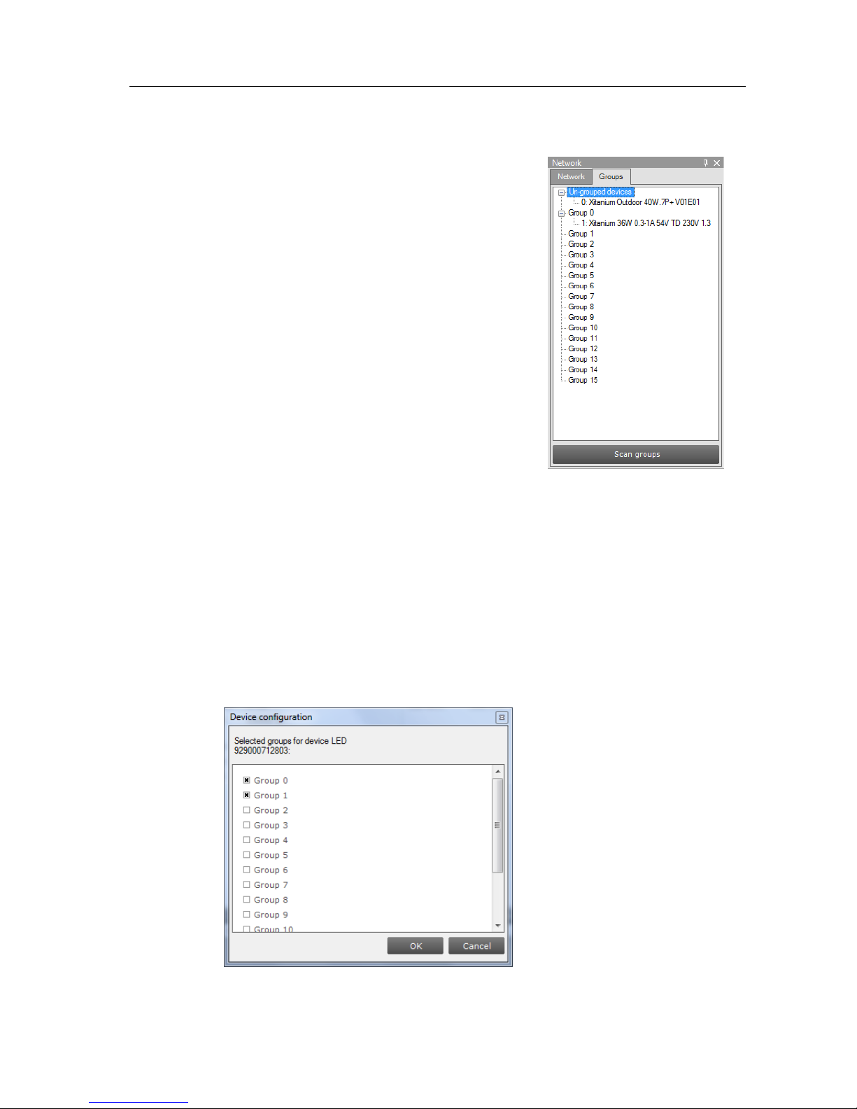
Once all the devices in the DALI network are
commissioned, i.e. have a unique short address, it is
possible to work with DALI groups.
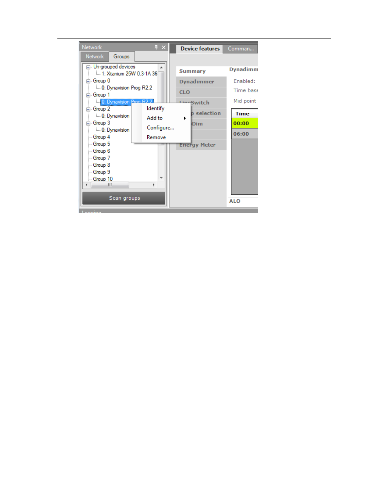
Select the Groups tab and press Scan groups. After
having scanned the network for groups, the Groups tab
shows all the DALI groups and the found devices for every
group.
DALI groups are much more comprehensive than userdefined groups. The important difference is that with DALI
grouping information is stored in the devices themselves.
Therefore, DALI grouping is more permanent than userdefined grouping.
By clicking on a device you will make that particular device the active one, meaning
that all actions will be performed on this device only, and will be ignored by all other
devices.
The options are:
With a right-click on an un-grouped device you can:
o Identify the device
o Add to, add the device to one group
o Configure…, add device to multiple groups
With a right-click on a device in a group you can:
Page 19
User Manual Philips MultiOne
© Philips Lighting B.V. 2014 Page 19 / 81
o Identify the device
o Add to, add the device to one other group
o Configure…, add/remove device to/from multiple groups
o Remove, remove device from current group
Besides selecting a single device for communication, it is also possible to
communicate with a group of devices.
The options are:
With a right-click on a group you can:
o Identify the devices in the group
o Configure…, add/remove multiple devices to/from the group
o Clear group, remove the devices from the group
The number of devices in a DALI group is limited to 64.
Page 20

User Manual Philips MultiOne
© Philips Lighting B.V. 2014 Page 20 / 81
10 Working with the Philips LCN8650 MultiOne interface
USB2ZigBee
10.1 The main application window
If in the Application Mode Selector screen All is selected as application mode, the
program will start as follows:
10.2 Connecting to a ZigBee network
The Network panel is used to manage a connected ZigBee network. A
number of tasks can be performed in the Network panel, each of which
is detailed below.
10.2.1 Identify devices
The ZigBee devices and networks in the area of the USB2ZigBee
interface are not automatically known. To find devices and networks in
the area press Connect to network: MultiOne scans for an open
network in the area and connects to the network. After connecting has
finished, the network and the found devices are shown in the Network
panel.
Page 21
User Manual Philips MultiOne
© Philips Lighting B.V. 2014 Page 21 / 81
10.2.2 Selecting devices for communication
After having connected to the network, the Network panel shows all devices and the
network to which MultiOne is connected. By clicking on a device or network you will
make that particular device or network the active one, meaning that all actions will be
performed on this device or network only, and will be ignored by all other devices or
networks.
With a right click on a device you can
Identify the device
10.3 Advanced commissioning
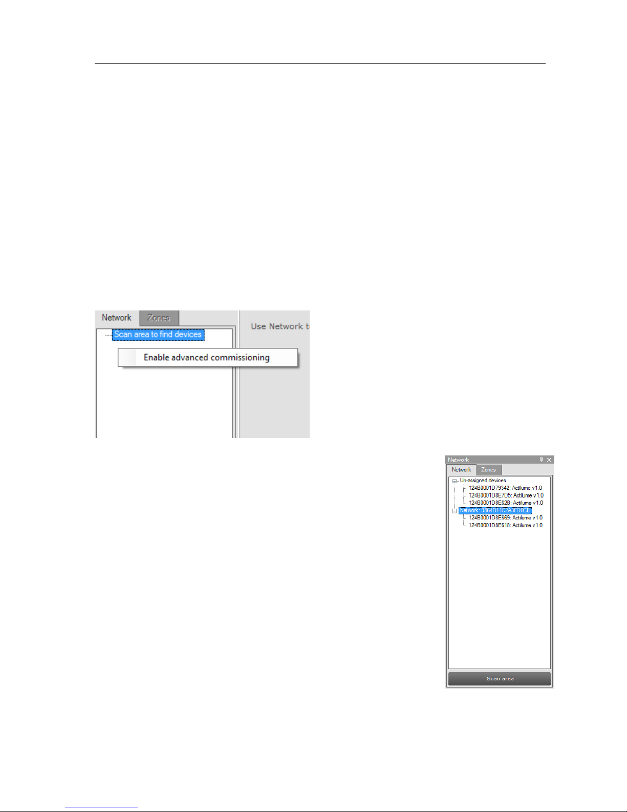
To commission a ZigBee network, right click the Network panel and choose Enable
advanced commissioning.
The Network panel switches to a different view making it possible
to manage ZigBee networks.
10.3.1 Identify devices
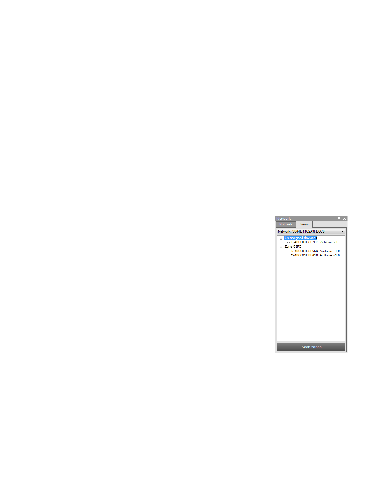
Press Scan area to scan for all the devices and network in the area
of the USB2ZigBee interface. After scan has finished the devices
and networks in range of the interface are shown in the Network
panel.
Page 22
User Manual Philips MultiOne
© Philips Lighting B.V. 2014 Page 22 / 81
10.3.2 Managing networks
The options are:
With a right-click on an unassigned device you can:
o Add to, move the device to an existing network or move the device to a
new network
With a right-click on a device in a network you can:
o Add to, move the device to an existing network or move the device to a
new network
o Reset, from network, the device will become unassigned. If the network
becomes empty, the network will be removed
With a right-click on a network you can:
o Query network, to find all devices in the network, including the devices
that are out of range of the USB2ZigBee interface
o Open network, to add more devices
10.3.3 Managing zones
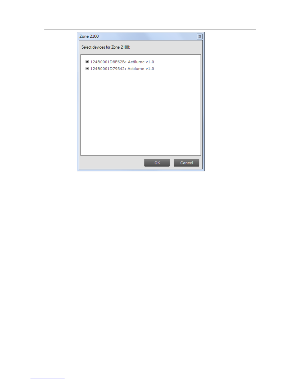
Once you have scanned the area and found devices and networks
in range, it is possible to scan a specific network for zones. Select
the Zones tab, select the Network and press Scan zones. After
having scanned the network, the Zones tab shows the found
devices and zones within the specified network.
By clicking on a device or zone you will make that particular device
or zone the active one, meaning that all actions will be performed
on this device or zone only, and will be ignored by all other devices.
With a right-click on an unassigned device you can:
o Identify the device
o Add to, move the device to an existing or new zone
With a right-click on a device in a zone you can:
o Identify the device
o Add to, move the device to an another or new zone
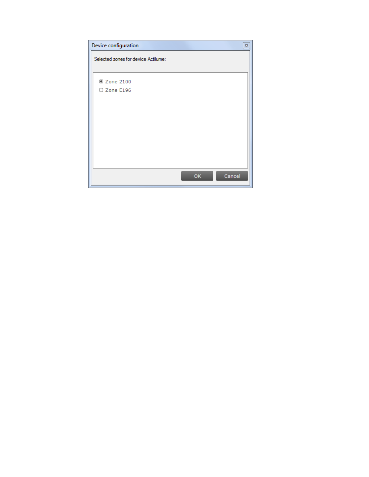
o Configure…, move the device to another zone
Page 23
User Manual Philips MultiOne
© Philips Lighting B.V. 2014 Page 23 / 81
o Remove, the device will become unassigned. If the zone becomes
empty, the zone will be removed
With a right-click on a zone you can:
o Identify the zone
o Configure…, add/remove multiple devices to/from the zone. If other
zones become empty, they will be removed
Page 24
User Manual Philips MultiOne
© Philips Lighting B.V. 2014 Page 24 / 81
o Remove zone, the zone will be removed and the devices will become
unassigned
Page 25

User Manual Philips MultiOne
© Philips Lighting B.V. 2014 Page 25 / 81
11 Working with the Philips LCN9600 MultiOne interface
SimpleSet
11.1 The main application window
If in the Application Mode Selector screen All is selected as application mode, the
program will start as follows:
11.2 Scanning a SimpleSet device
The Network panel is used to manage the scanned SimpleSet
devices. A number of tasks can be performed in the Network panel,
each of which is detailed below.
11.2.1 Identifying devices
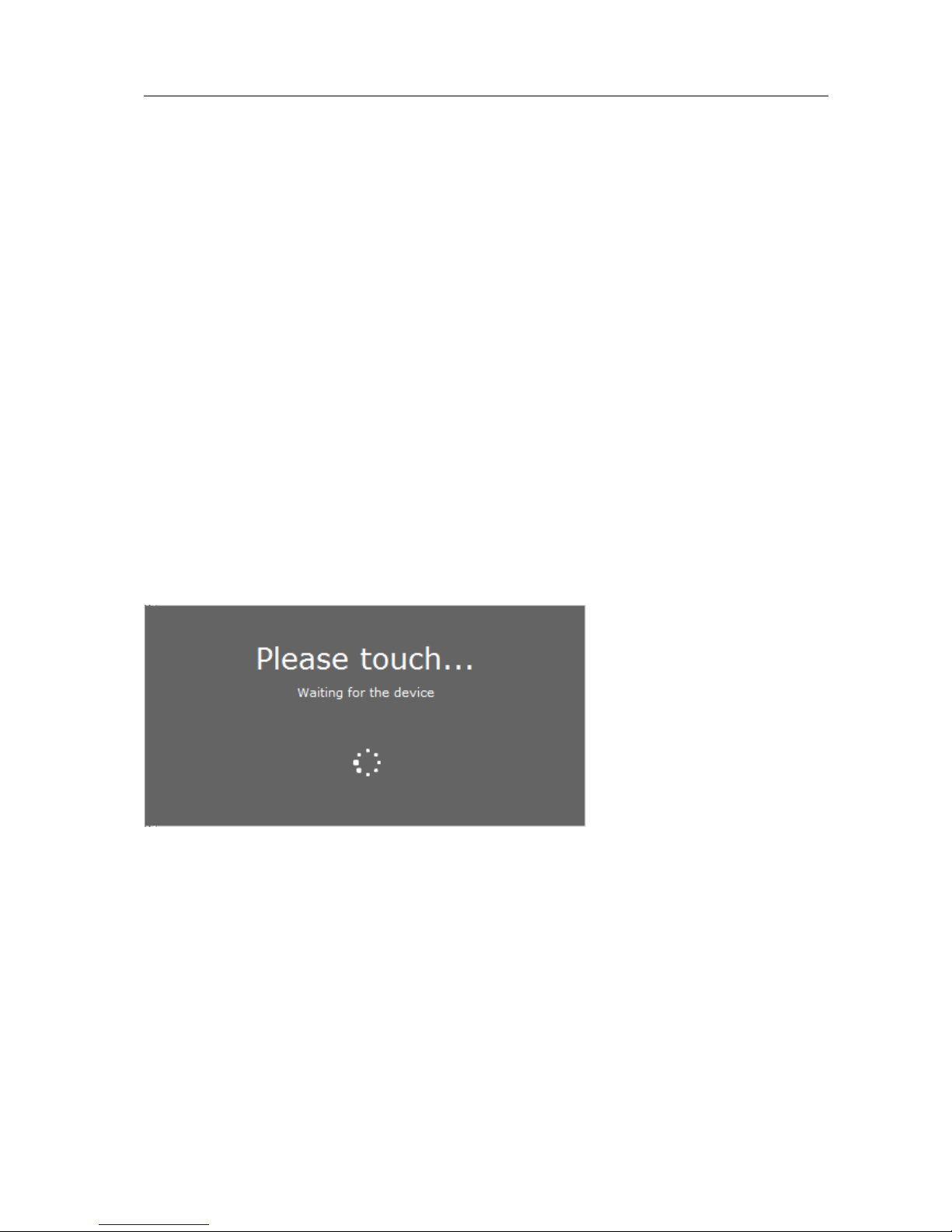
The SimpleSet device near the SimpleSet interface is not
automatically known by MultiOne. To get the device press Scan for
device: a pop-up will appear indicating the device must touch the
interface. Touch and hold the device close to the SimpleSet interface
Page 26

User Manual Philips MultiOne
© Philips Lighting B.V. 2014 Page 26 / 81
until the scan has completed. The scanned device will be shown in the Network
panel.
Page 27
User Manual Philips MultiOne
© Philips Lighting B.V. 2014 Page 27 / 81
11.2.2 Auto read
After a device gets selected all features are shown on the Features tab and auto read
gets activated. Auto read automatically start reading the configuration of all features.
Progress is shown as described in chapter 12.2
11.3 Selecting devices for communication
After having scanned the SimpleSet device, the Network panel shows the device. By
clicking on a device you will make that particular device the active one, meaning that
all actions will be performed on this device only, and will be ignored by all other
devices.
11.4 Starting communication
In order to communicate with a SimpleSet device, the device has to touch the
SimpleSet interface. Before starting the communication MultiOne will show a pop-up
when the device is not near the SimpleSet interface. This pop-up waits until the
device and the SimpleSet interface touch, or disappears after 20 seconds. After
touching the action will be executed. Touch and hold the device close to the
SimpleSet interface until all communication has finished.
Page 28
User Manual Philips MultiOne
© Philips Lighting B.V. 2014 Page 28 / 81
12 Working with MultiOne
12.1 Viewing device properties
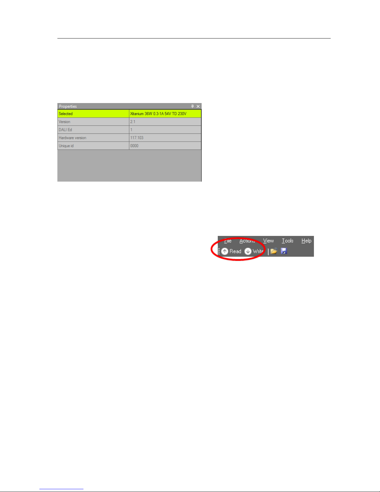
Whenever a device is selected in Network, the Properties display a number of
details for the selected device.
12.2 Communicating with a device
Initiating communication with a device is done by first selecting the device (left-click
the device in Network) and then clicking Read or Write on the toolbar. When the
Commands tab or the Scheduler tab is active, these buttons are unavailable. When
the Query tab is active, all queries are executed
when clicking Read. When the Diagnostics tab is
active, all diagnostics information is read (if
available in the selected device) when clicking Read. When the Device features tab is
active, both Read and Write actions are available.
Reading and writing will always take a few seconds. Operation progress is shown on
the status bar of the main application window. On the Device features tab, perfeature progress is shown on each of the feature selection tabs. When all information
has been successfully read or written, a green tick mark will appear and the text
Status: OK is shown. If anything goes wrong, a red icon and the text Status: failed is
shown. When on the Device features tab, point your mouse to each status icon to
see a more detailed description of the communication result.
Apart from using Read and Write on the toolbar, you can directly send DALI
commands. This can be done on the Commands tab and the Scheduler tab.
In the Preferences window it is possible to enable extra verification when writing (see
chapter 12.15).
Page 29
User Manual Philips MultiOne
© Philips Lighting B.V. 2014 Page 29 / 81
12.3 Configuring device features
You can configure all features that are supported by a specific Philips device. For any
device selected in the Network, the Device features tab displays the set of device
features that corresponds to this device. Upon selecting another device, the Device
features tab will be updated as well. This mechanism ensures that only the features
supported by the selected device can be configured.
The Device features tab has a panel with a column of tabs on the left-hand side.
Each feature has its own tab. For most devices a Summary tab is available as well.
To make sure that the feature information in the
Device features tab corresponds to the
selected device, click Read on the toolbar.
To make sure that the feature information is stored in the selected device, click Write
on the toolbar.
For both Read and Write status icons will be
shown when a feature is being read or written.
There are three different colors used for the icons:
red, green and grey. Red means that the reading
or writing has failed. The green icon indicates that
the reading was successful and that all the data
was sent to the driver. This does not mean that all
data is actually received (see Write and Verify in
chapter 21). The grey icon is used to display that
Write
Read
Page 30

User Manual Philips MultiOne
© Philips Lighting B.V. 2014 Page 30 / 81
the read or write action is pending for the specific feature.
In the following sections you will find an overview of all supported device features in
alphabetical order. Features typically belong to one or two product groups (LED, HID
or FLUO), but this does not mean that every device belonging to a certain product
group will automatically support all of its features listed here. For an overview of
supported device features see Supported features.
Page 31
User Manual Philips MultiOne
© Philips Lighting B.V. 2014 Page 31 / 81
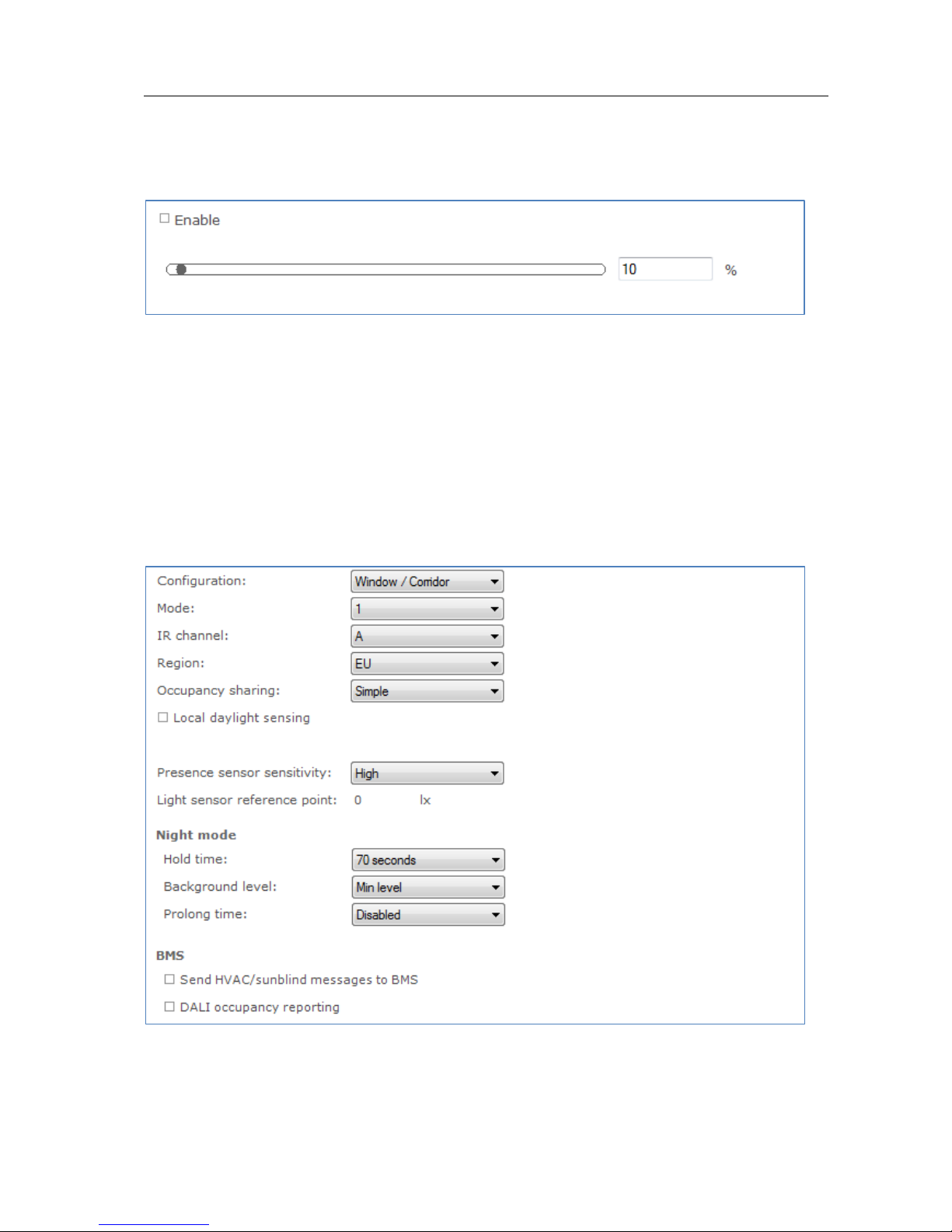
12.3.1 1-10V min dim level
Product group
LED
Description
Use this feature to set the minimum dim level when using 1-10V dimming interface.
Usage
Use the slider or the text field to select a value. The value represents the light level.
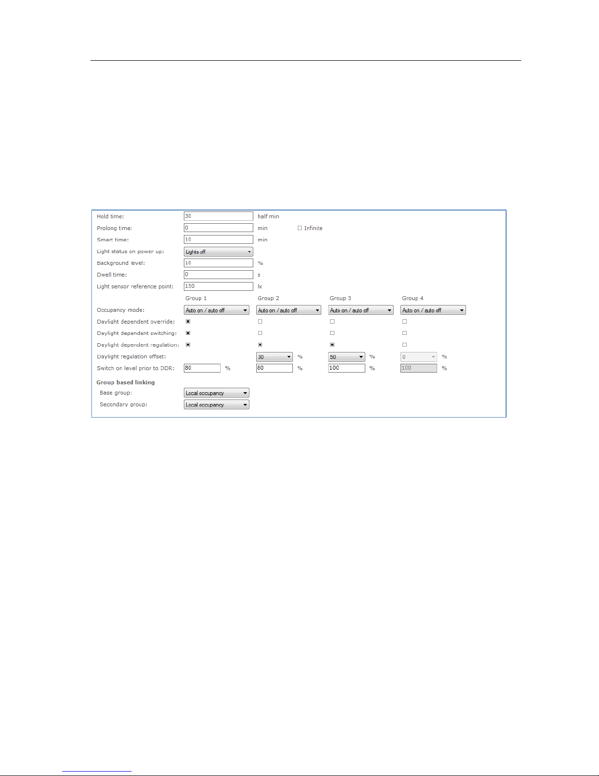
12.3.2 ActiLume General
Product group
CONTROL
Description
Use this feature to configure general ActiLume settings.
Page 32
User Manual Philips MultiOne
© Philips Lighting B.V. 2014 Page 32 / 81
Usage
Use the various drop down boxes, check boxes and text fields to make a
configuration.
Please refer to the ActiLume DALI gen2 Application Guide for further details.
12.3.3 ActiLume Mode
Product group
CONTROL
Description
Use this feature to configure ActiLume settings that apply to the system’s modes. For
ActiLume DALI gen2, up to 16 modes are shown, each of which has its own feature
tab on the left-hand side. Use the ActiLume Mode feature to configure settings for
each individual mode.
Usage
Use the various drop down boxes, check boxes and text fields to make a
configuration. Click the Reset to factory defaults button to reset the current mode
to the factory defaults.
Please refer to the ActiLume DALI gen2 Application Guide for further details.
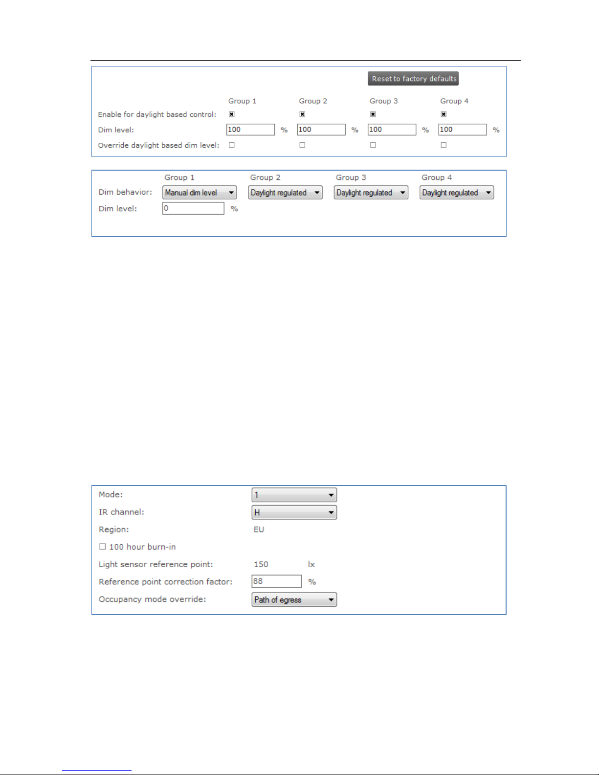
12.3.4 ActiLume Scene
Product group
CONTROL
Page 33
User Manual Philips MultiOne
© Philips Lighting B.V. 2014 Page 33 / 81
Description
Use this feature to configure ActiLume settings that apply to the system’s scenes. For
ActiLume DALI gen2, 4 modes are shown, each of which has its own feature tab on
the left-hand side. Use the ActiLume Scene feature to configure settings for each
individual scene.
Usage
Use the various check boxes and text fields to make a configuration. Click the Reset
to factory defaults button to reset the current scene to the factory defaults.
Please refer to the ActiLume DALI gen2 Application Guide for further details.
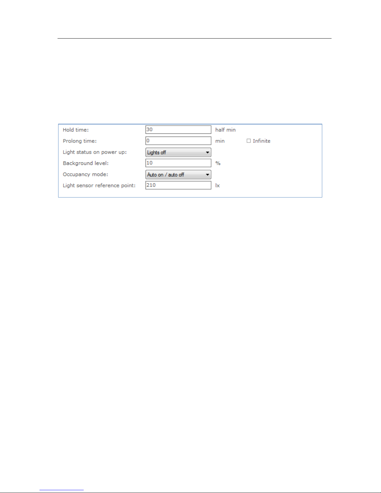
12.3.5 ActiLume Wireless General
Product group
CONTROL
Description
Use this feature to configure general ActiLume Wireless settings.
Usage
Page 34
User Manual Philips MultiOne
© Philips Lighting B.V. 2014 Page 34 / 81
Use the various drop down boxes, check boxes and text fields to make a
configuration.
Please refer to the ActiLume Wireless Application Guide for further details.
12.3.6 ActiLume Wireless Mode
Product group
CONTROL
Description
Use this feature to configure ActiLume Wireless settings that apply to the system’s
modes. For ActiLume Wireless, up to 32 modes are shown, each of which has its own
feature tab on the left-hand side. Use the ActiLume Wireless Mode feature to
configure settings for each individual mode.
Usage
Use the various drop down boxes, check boxes and text fields to make a
configuration.
Please refer to the ActiLume Wireless Application Guide for further details.
12.3.7 Active Cooling
Product group
LED
Page 35
User Manual Philips MultiOne
© Philips Lighting B.V. 2014 Page 35 / 81
Description
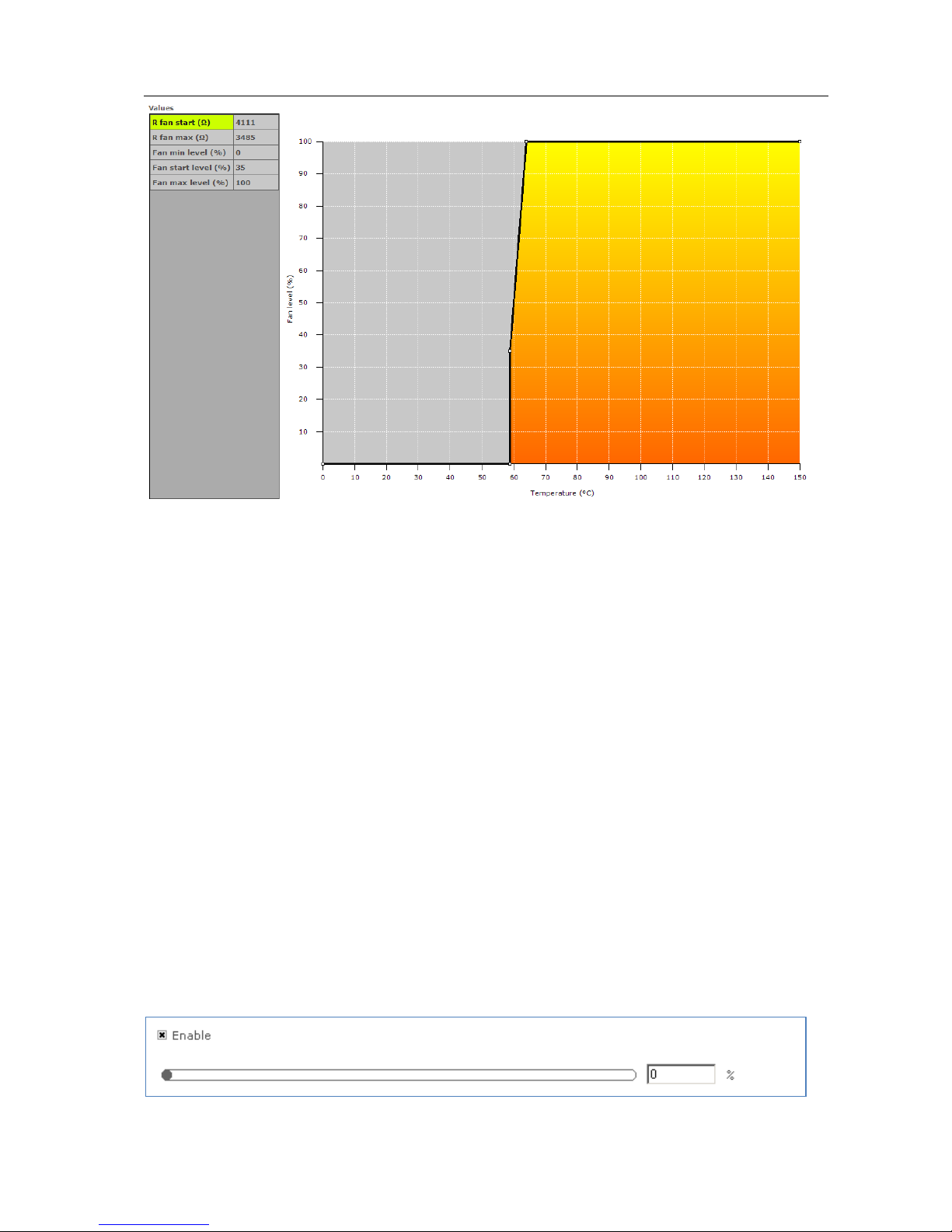
Use this feature to control the fan of the LED module and minimize audible noise
from the active cooling unit. The driver increases the fan output level (and so the
speed of the fan) when temperature of the LED module becomes too high. When the
fan output level increases the temperature of the LED module should be reduced.
The customer can specify the temperature limits to make sure the fan output level is
kept as low as possible and will only increase when needed so the audible noise is
reduced.
Usage
Drag the points or the lines in the resulting graph to adjust the configuration.
Alternatively, use the table to enter values directly.
NOTE: For a detailed technical description of the characteristics of the device model,
like constraints and limitations, please refer to Device-specific technical description.
12.3.8 Adjustable Light Output
Product group
HID
Page 36
User Manual Philips MultiOne
© Philips Lighting B.V. 2014 Page 36 / 81
Description
Use the Adjustable Light Output (ALO) feature to regulate the light output to a
desired optimum value. You can create a “virtual lamp” with output different than
what the standard wattages offer.
Usage
Select the Enable check box to use this feature. Use the slider or the text field to
select a value. The value represents the light level.
12.3.9 Adjustable Output Current
Product group
LED
Description
Use this Adjustable Output Current (AOC) feature to adjust the output current to a
desired optimum value. You can create a “virtual lamp” with output different than
what the standard wattages offer.
Usage
The current can be set in two ways:
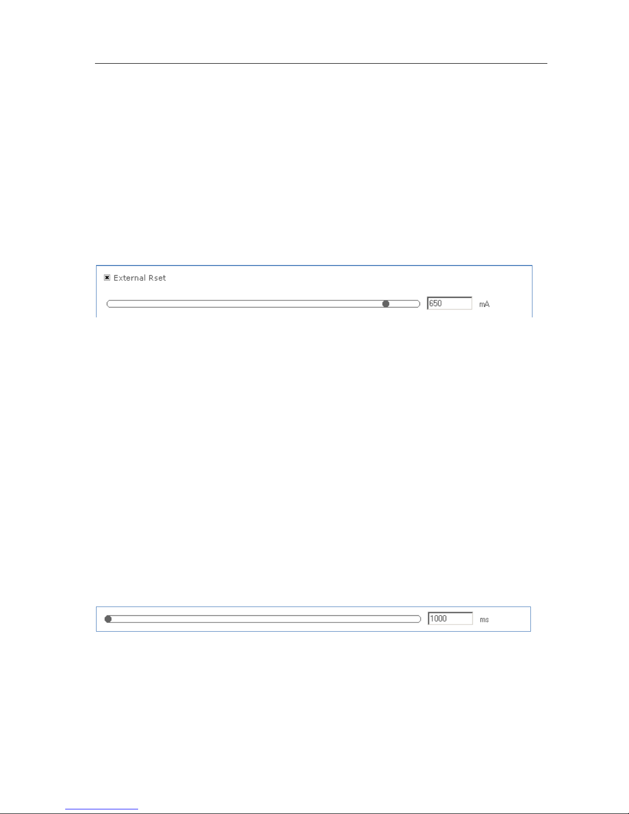
Select the External Rset check box: Adjustment of the output current is not
configured using MultiOne, but the value of an external resistor adjusts the
output current
OR
Use the slider or the text field to select a value. The value represents the
nominal output current
12.3.10 Adjustable Startup Time
Product group
LED
Description
At power on, the fast fade-up of light can be unpleasant in certain applications. To
avoid such a situation, the device fade-up time at startup can be adjusted.
Usage
Page 37
User Manual Philips MultiOne
© Philips Lighting B.V. 2014 Page 37 / 81
Use the slider or the text field to select a value. The value represents the start fade-up
time in milliseconds.
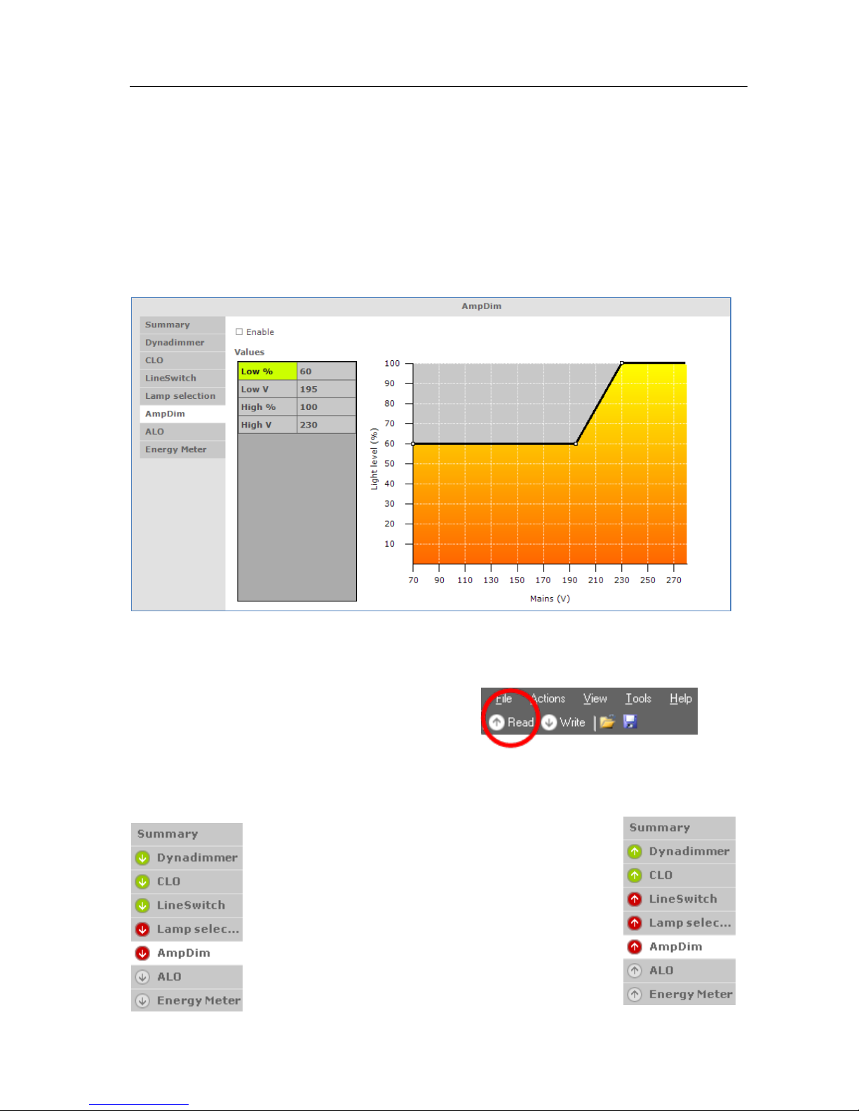
12.3.11 AmpDim
Product group
HID, LED
Description
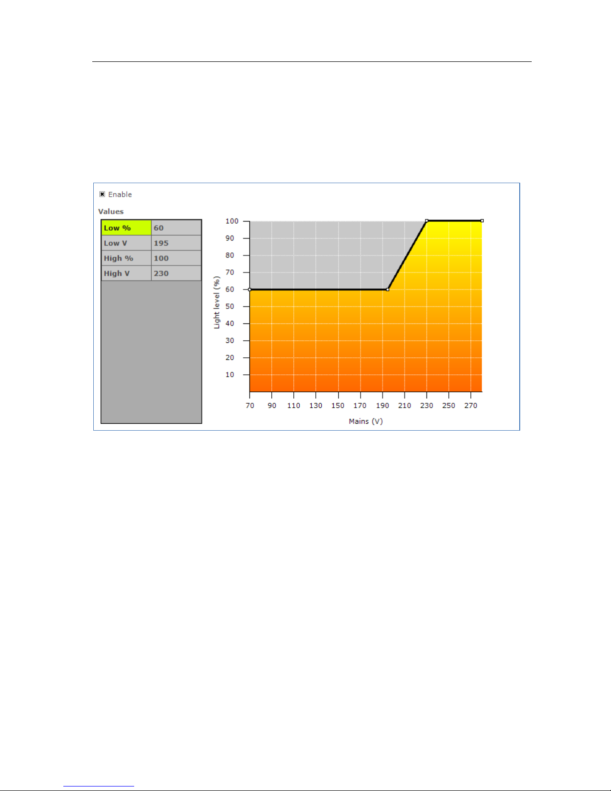
Use this feature to adjust the light output of a lamp by adjusting the mains voltage of
the device.
Usage
Select the Enable check box to use this feature (note that LED devices do not have
this check box). Drag the points or the lines in the graph to create the desired
configuration. Alternatively, use the table to directly enter values.
NOTE: For a detailed technical description of the characteristics of the device model,
like constraints and limitations, please refer to Device-specific technical description.
Page 38
User Manual Philips MultiOne
© Philips Lighting B.V. 2014 Page 38 / 81
12.3.12 Constant Light Output
Product group
HID, LED
The HID version of Constant Light Output (CLO) has two check boxes. Select the
Enable check box to use the device’s built-in Constant Light Output profile. Select the
Reset check box to reset this feature, including resetting the lamp operating hours
parameters. This is useful when replacing the HID lamp.
The Constant Light Output feature for LED devices will show the following window:
Description
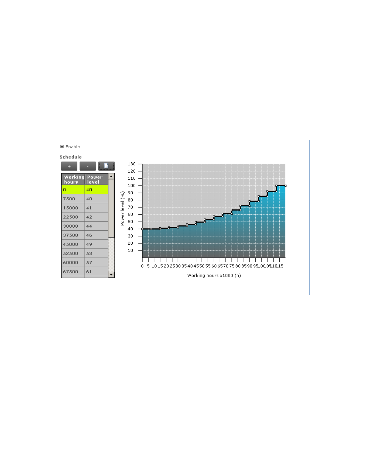
The lumen output of a LED module usually decreases over its lifetime. To
compensate, a schedule can be created that gradually increases the lamp’s power
level over time.
Usage
Select the Enable check box to use this feature. Click the New button to create a
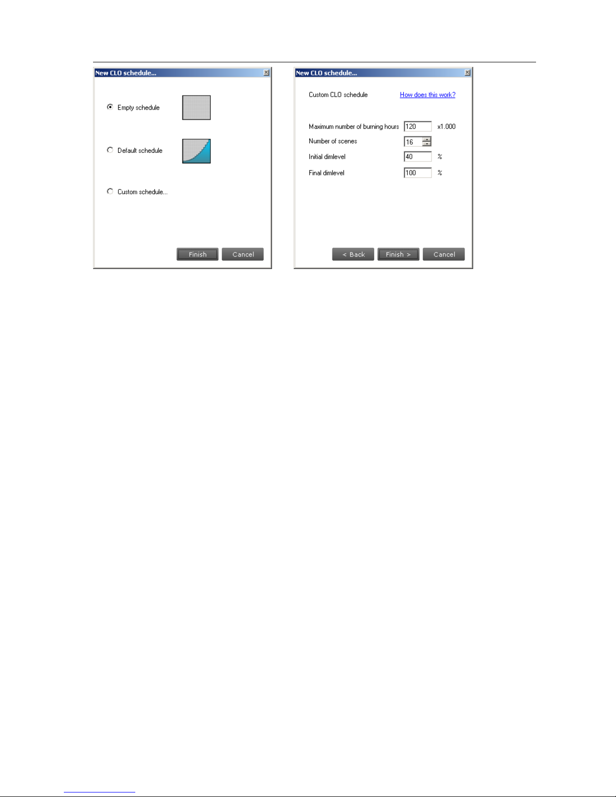
default schedule or click the Plus button to individually add scenes. When creating a
new schedule, in the dialog window that pops up you can either select an empty
schedule, a default schedule or a custom schedule.
Page 39
User Manual Philips MultiOne
© Philips Lighting B.V. 2014 Page 39 / 81
When selecting a custom schedule, you have to enter a number of parameters that
will define the CLO schedule. These are:
Maximum number of burning hours: the largest number of burning hours
for which the CLO schedule is defined. This corresponds to the maximum value
of the horizontal axis in the resulting CLO graph.
Number of scenes: the number of scenes (bars in the graph) into which the
total number of burning hours is divided
Initial dimlevel: the power level that is the starting point at 0 burning hours
Final dimlevel: the power level at the end of the defined lifetime (the value
given for maximum number of burning hours)
After clicking Finish a CLO schedule will be created using linear interpolation of the
provided values.
Drag the points or the lines in the resulting graph to adjust the configuration.
Alternatively, use the table to enter values directly. Single or multiple table rows can
be removed by clicking the Minus button.
NOTE: The reliable use of Constant Light Output requires extensive LED specification
assessment of life time behavior of LEDs.
Page 40
User Manual Philips MultiOne
© Philips Lighting B.V. 2014 Page 40 / 81
12.3.13 Corridor Mode
Product group
FLUO, LED
Description
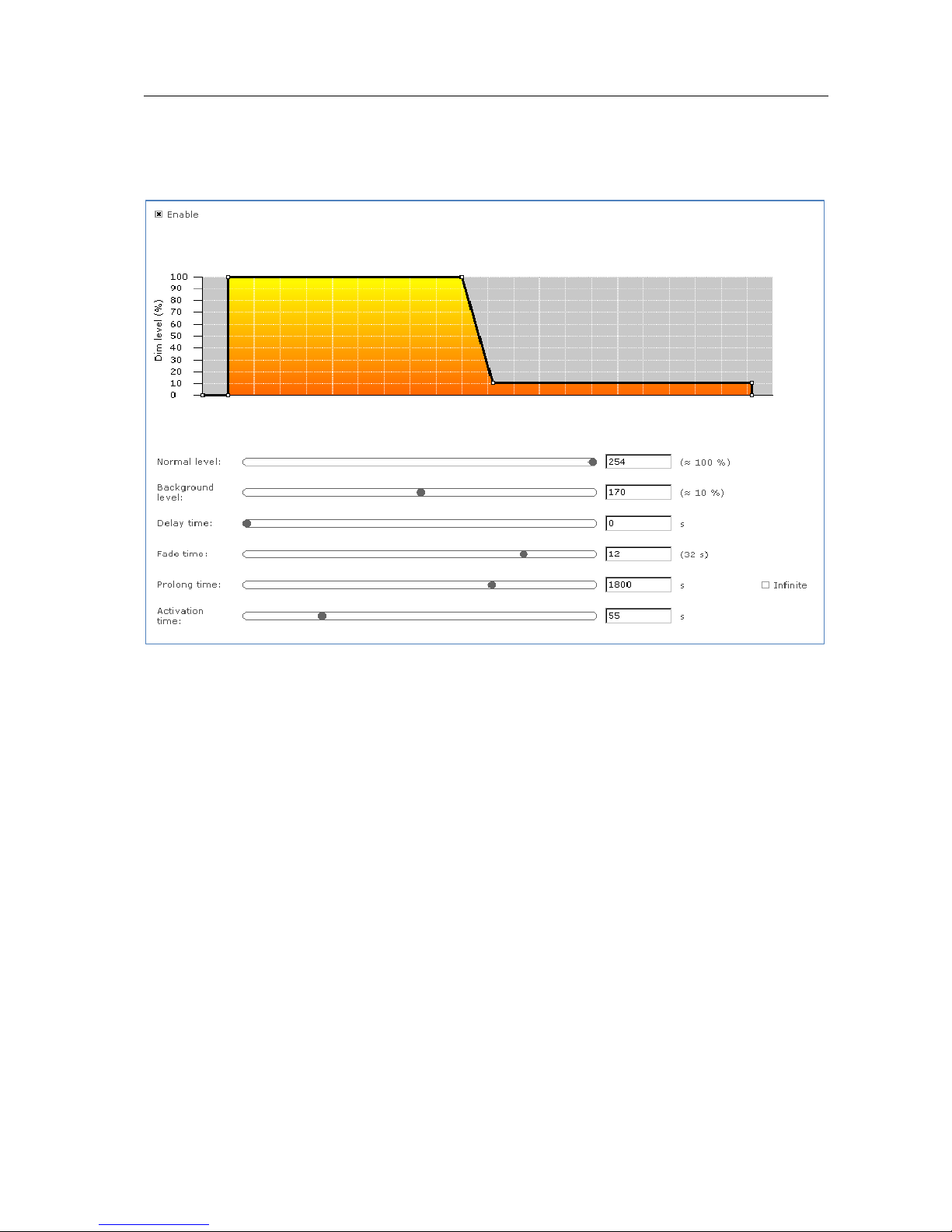
Corridor Mode feature depends on Touch and Dim feature. The Corridor Mode
feature adjusts the light to a defined level when a presence sensor detects a person.
Corridor Mode can only be activated when the device is in Touch and Dim mode.
Usage
Select the Enable check box to use this feature. This feature has the following
parameters:
Normal level: Light level to be set when presence sensor detects activity
Background level: Low light level to be set when no presence is detected
after the fade time
Delay time: The time from the moment the sensor has switched off and the
moment the device will start to fade to background level
Fade time: The time used to fade from normal level to background level
Prolong time: When reaching background level, the time after which the
device will be switched off
Activation time: The time during which a mains signal must be detected,
before the device will switch to Corridor Mode
Page 41
User Manual Philips MultiOne
© Philips Lighting B.V. 2014 Page 41 / 81
Alternatively to using the sliders, some lines and points in the graph can be dragged
to adjust the configuration.
12.3.14 Dimming Interface
Product group
LED
Description
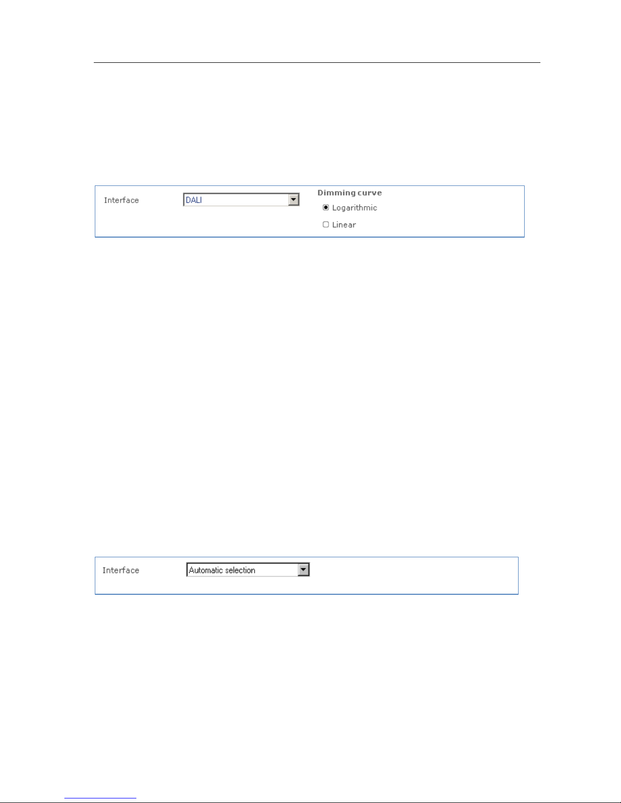
Use the Dimming Interface feature to select the dimming interface for the device. The
actual options are depending on the device model:
1-10 V
DALI
Dynadimmer
No dimming
AmpDim
LineSwitch
When DALI has been selected, an additional setting appears with which the dimming
behavior can be set. Options are Logarithmic and Linear dimming curves.
Usage
Use Dimming Interface to select the desired dimming interface.
Product group
FLUO, LED
Description
Use the Dimming Interface feature to select the dimming interface for the device.
Usage
The available dimming interfaces are stored in the device and therefore need to be
read out. When the interfaces are found it will be possible to select Automatic
selection (enable all interfaces), No dimming (disable all interfaces) or a single
interface.
Page 42
User Manual Philips MultiOne
© Philips Lighting B.V. 2014 Page 42 / 81
12.3.15 Dynadimmer
Product group
HID, LED
Description
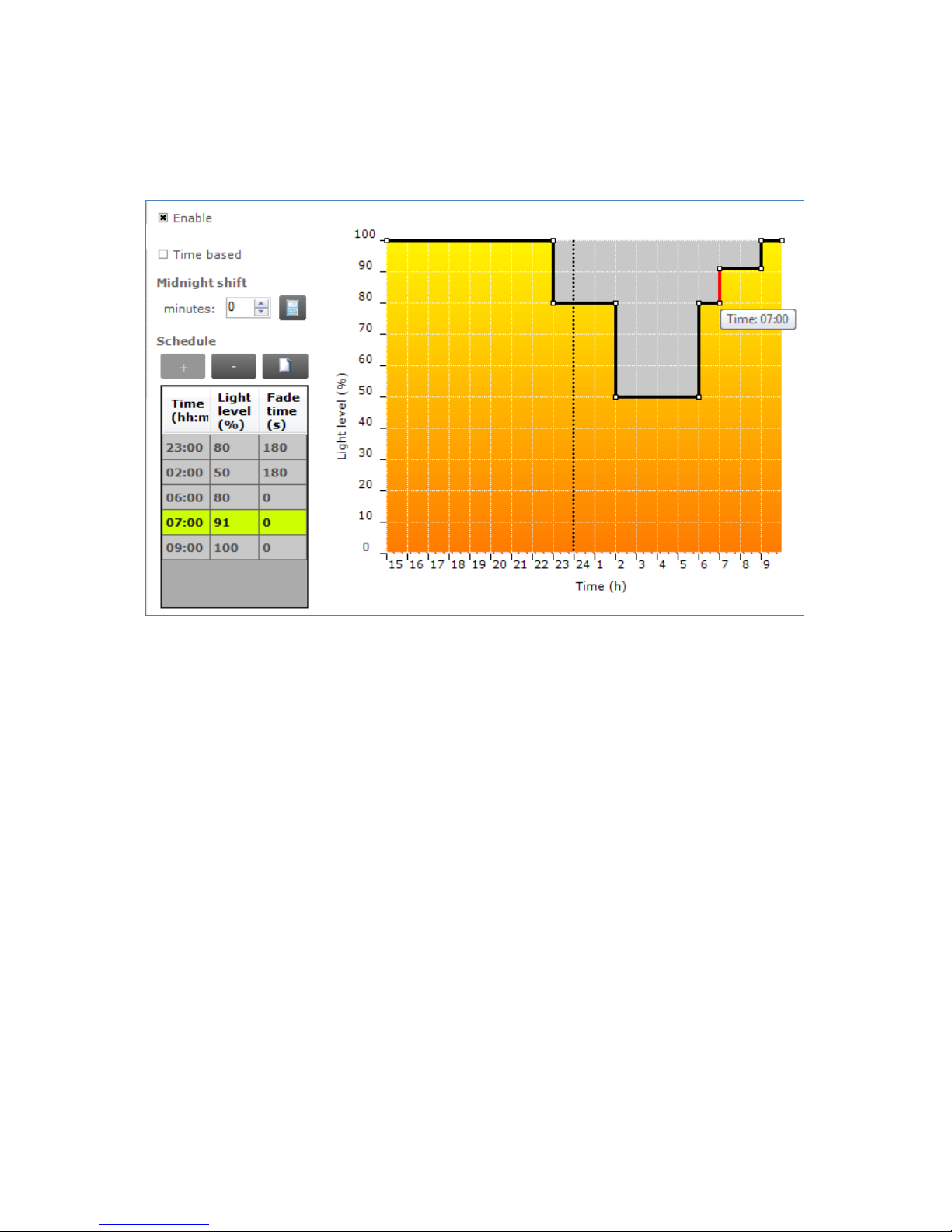
Use Dynadimmer to create a dynamic dimming schedule over a period of time.
Usage
Select the Enable check box to use this feature. This feature has a number of options,
depending on the device model:
Time based: switch between absolute and relative time schedules. When the
Time based check box is cleared, the Dynadimmer schedule will use its
automatically learned midnight point as a reference for timekeeping. When the
Time based check box is selected, the reference point is the moment when
the mains are switched on. Selecting the Time based check box changes the
graph and removes its dotted midnight line. Note that not all devices support
Time based Dynadimmer.
Midnight shift: the midnight point depends on the geographical location.
Enter the midnight shift in minutes or use the midnight shift calculation
window to automatically adjust the midnight point by the specified offset. Use
the calculation button to either manually provide latitude and longitude
coordinates or to choose a predefined location. The midnight shift option is
unavailable when the Time based check box has been selected.
Page 43
User Manual Philips MultiOne
© Philips Lighting B.V. 2014 Page 43 / 81
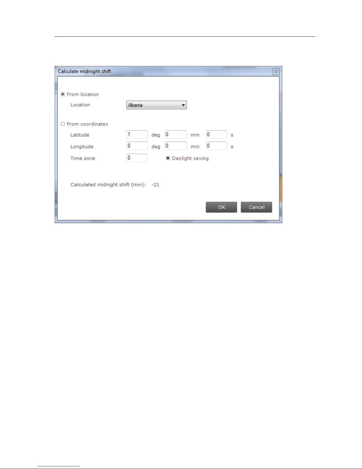
The midnight shift calculation dialog window looks as follows:
Location: a name that identifies this custom location.
Latitude: the latitude of the location in degrees, minutes and seconds. The
value that represents the degrees can be negative.
Longitude: the longitude of the location in degrees, minutes and seconds. The
value that represents the degrees can be negative.
Time zone: the time zone of the location. For GMT+1 enter 1, for GMT-1 enter
-1, and so on.
Daylight saving: indication whether daylight saving should be dealt with or
not.
You have two choices for calculation of midnight shift. If your location is available in
the location list you can use it. Some locations are not listed. For those unlisted
locations use the geographical coordinates to calculate the correct midnight shift.
Click OK to save result of your calculation as the new midnight shift. Note that
clicking OK is not directly saving your data to the driver. To save midnight shift to a
driver you will have to write the whole feature. Note also that the location is not
written into the driver, the midnight shift is written instead.
Click the New button to create a default schedule or click the Plus button to add
scenes individually. Drag the points or the lines in the graph to create the desired
Page 44
User Manual Philips MultiOne
© Philips Lighting B.V. 2014 Page 44 / 81
configuration. Alternatively, use the table to enter values directly. Remove single or
multiple table rows by clicking the Minus button.
NOTE: The device will follow the dimming schedule. When the light level in the
dimming schedule is below the physical min level of the selected lamp, the physical
min level will be used. However, some devices are also capable to switch off during
the dimming schedule, if a scene was configured at 0 %.
The physical min level of the selected lamp is indicated by the gray-dotted line in the
graph.
12.3.15.1 Physical min level
In order to see the correct physical min level of a lamp after Lamp Selection, do not
forget to switch the driver off for a few seconds. After switching it on again the
selected lamp is activated. To see the physical min level of the selected lamp in the
graph, click Read on the toolbar.
12.3.15.2 Location or custom location
For some device models, only the midnight point offset is stored in the device and
NOT the (custom) location. In those cases the location information and the custom
location is only used to calculate the midnight point offset. After reading out the
device, MultiOne tries to match the midnight point offset with a location. In case the
midnight point offset does not match to a location or the midnight point offset
matches multiple locations, MultiOne will show “No location”.
For a technical description of the characteristics of the device model, like constraints
and limitations, please refer to Device-specific technical description.
12.3.16 DC Emergency
Product group
FLUO, LED
Description
This feature is used together with a DC central battery system. The device will dim to
a specific level, as soon as a DC voltage is detected at the mains input instead of an
Page 45

User Manual Philips MultiOne
© Philips Lighting B.V. 2014 Page 45 / 81
AC voltage on the mains input of the device. The dimming of the lamps can either be
enabled or disabled during this DC Emergency operation.
Usage
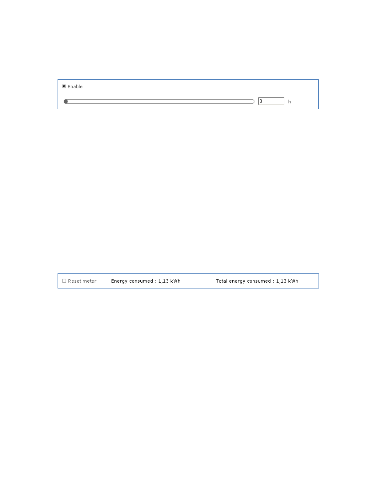
Select the Enable check box to use this feature. Use the slider or the text field to
select a value. The value represents the arc power level when in DC Emergency mode
(the label on the right gives the approximate light level percentage). Select the Allow
dimming check box to allow dimming when in DC Emergency mode.
Page 46
User Manual Philips MultiOne
© Philips Lighting B.V. 2014 Page 46 / 81
12.3.17 End Of Life indication
Product group
LED
Description
Use this feature to warn the user at the end of the guaranteed lifespan of the LED
module. Once the end of guaranteed life is reached, the device will flash the lamp for
5 seconds and then continue normal operation. LED flashing will happen every time
at startup once the device’s working hours have exceeded the number of hours
specified as End Of Life. This feature uses the same burning hours counter as the
Light Source Operating Hours and Constant Light Output features.
Usage
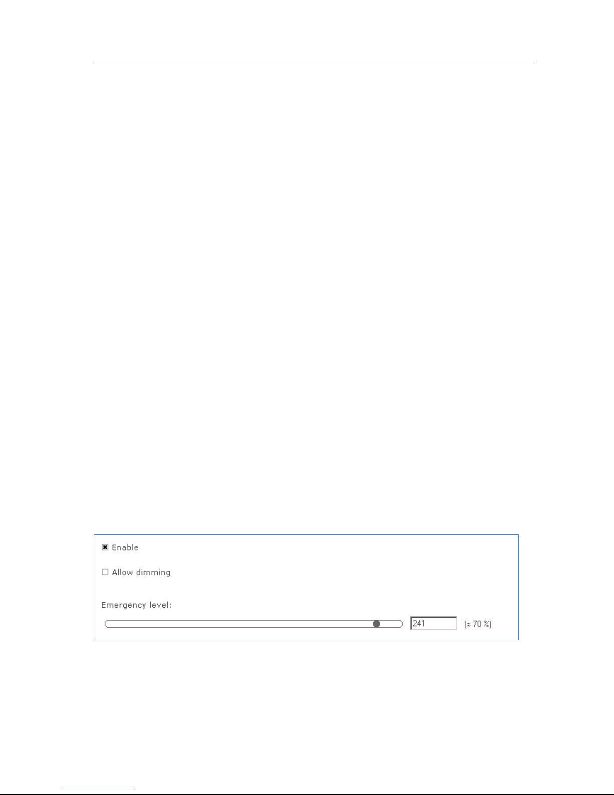
Select the Enable check box to use this feature. Use the slider or the text field to
select a value. The value represents the guaranteed lifetime in hours.
12.3.18 Energy Meter
Product group
FLUO, HID
Description
Use this feature to get an indication of the (total) energy consumption of the device.
Usage
The value for Energy consumed can be reset by selecting the Reset meter check box
followed by clicking Write on the toolbar. The value for Total energy consumed
cannot be reset.
Page 47
User Manual Philips MultiOne
© Philips Lighting B.V. 2014 Page 47 / 81
12.3.19 Lamp Burn-in
Product group
FLUO
Description
Lamp Burn-in prevents dimming below a predefined level in the first hours of a
lamp’s life. This is to ensure that the lamp will be properly “burned in” before
dimming.
Usage
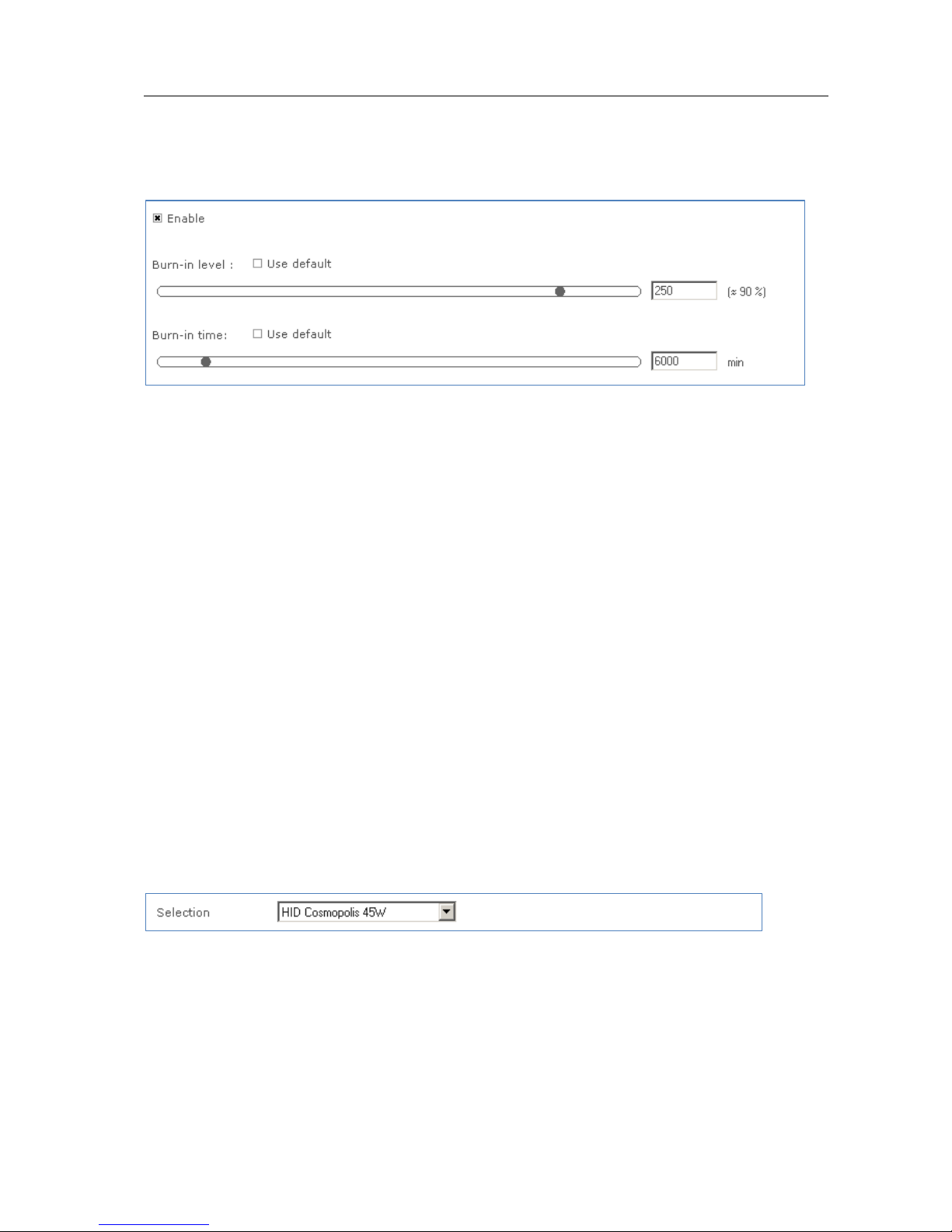
Select the Enable check box to use this feature. This feature has of two parameters:
Burn-in level: use the slider or the text field to select a value. The value
represents the maximum arc power level for dimming (the label on the right
gives the approximate light level in percent). Alternatively, select the Use
default check box to use the default value.
Burn-in time: use the slider or the text field to select a value. The value
represents the time in minutes during which the burn-in level is active.
Alternatively, select the Use default check box to use the default value.
12.3.20 Lamp Selection
Product group
HID, FLUO
Description
Use the Lamp Selection feature to select the lamp type that is connected to the
device. Options depend on the device model.
Usage
Page 48
User Manual Philips MultiOne
© Philips Lighting B.V. 2014 Page 48 / 81
Use Selection to select the lamp type. Note that this feature has to be read first in
order for the options to become available. To read the feature configuration, click
Read on the toolbar.
NOTE: after selecting a different lamp, it is necessary to switch the driver off for a few
seconds. After switching is on again the selected lamp is activated.
12.3.21 Light Source Operating Hours
Product group
LED
Description
Use this feature to manually set or reset the number of operating hours for the LED
module. This is useful when replacing the LED module, thereby resetting features like
Constant Light Output and End Of Life indication.
Usage
Use the slider or the text field to select a value. The value represents the number of
operating hours.
12.3.22 LineSwitch
Product group
HID, LED
Page 49
User Manual Philips MultiOne
© Philips Lighting B.V. 2014 Page 49 / 81
Description
This feature provides an interface for easy dimming via pilot-line or external sensor
(presence) of a group of lamps. Dimming to desired level can be controlled by
applying a 230V between the DALI inputs. The fade times can also be set using the
fade on-, fade off and switch off delay time.
Usage
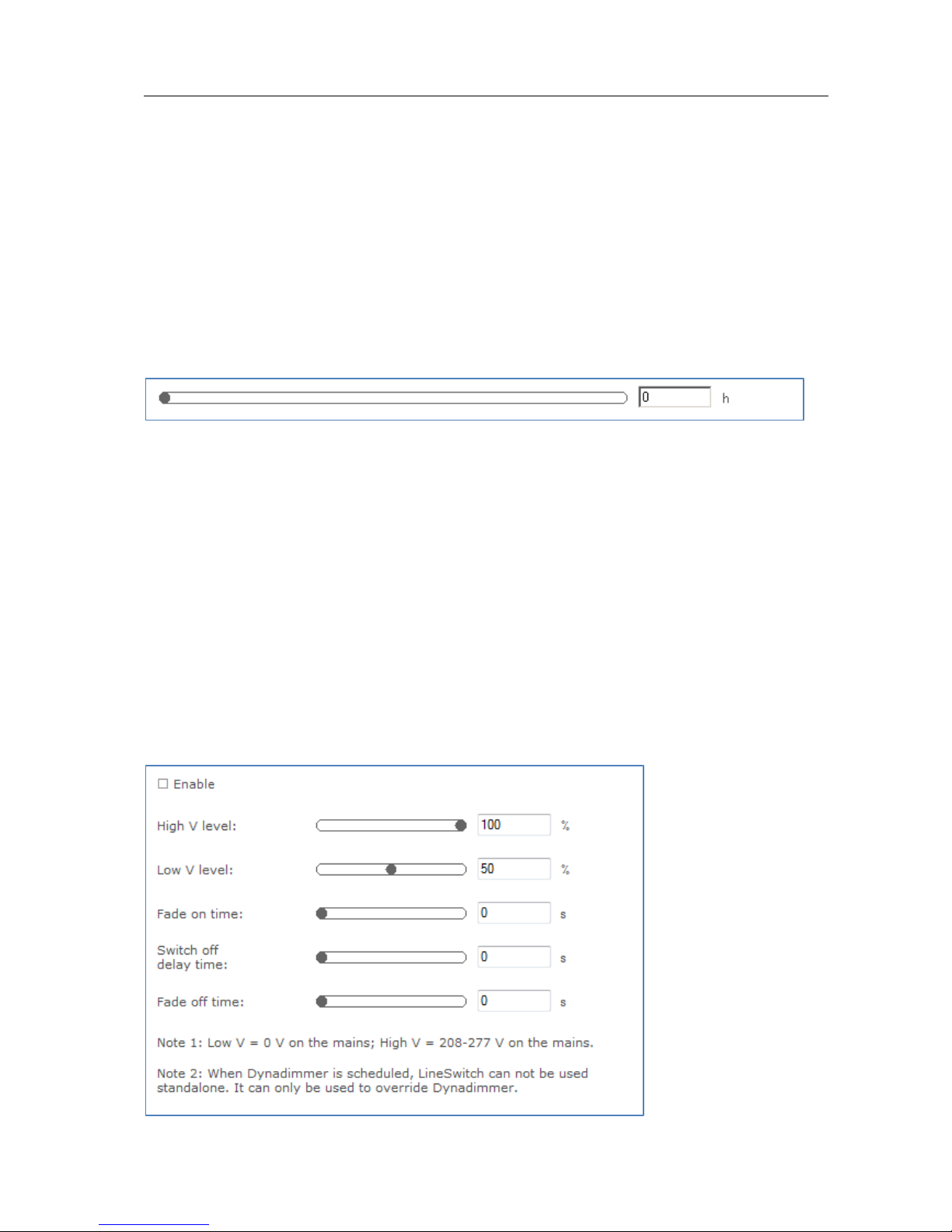
Select the Enable check box to use this feature. This feature has the following
parameters:
High V level: Use the slider or the text field to select a value. The value
represents the light level to be set when high voltage is detected on the mains.
Low V level: Use the slider or the text field to select a value. The value
represents light level to be set when low voltage is detected on the mains.
Fade on time: Use the slider or the text field to select a value. The value
represents the fade on time to be used.
Switch off delay time: Use the slider or the text field to select a value. The
value represents the switch off delay time to be used.
Fade off time: Use the slider or the text field to select a value. The value
represents the fade off time to be used.
12.3.23 LumiStep
Product group
LED
Description
This feature provides a simplified version of Dynadimmer.
Usage
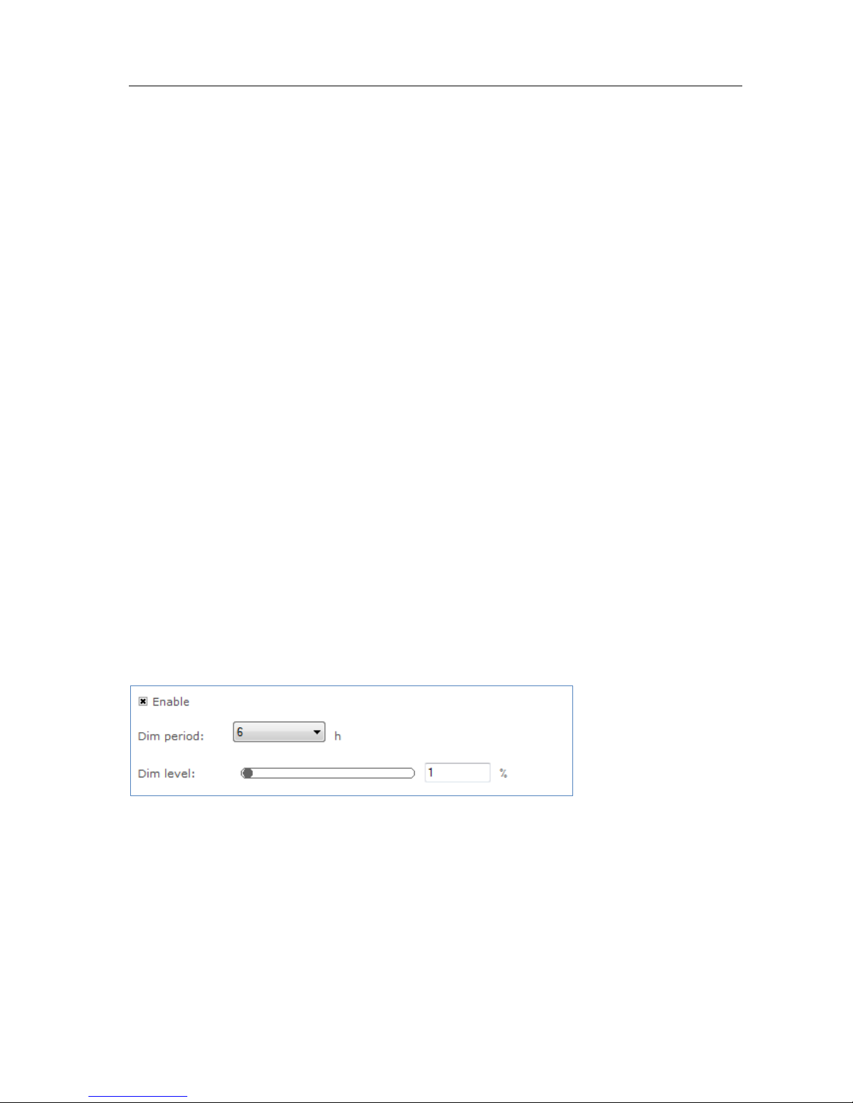
Select the Enable check box to use this feature. This feature has the following
parameters:
Dim period: Use the drop down box to select the wanted dim period. This is
the time period the dim level will be used.
Page 50

User Manual Philips MultiOne
© Philips Lighting B.V. 2014 Page 50 / 81
Dim level: Use the slider or the text field to select a value. The value
represents the dim level in percent. The dim level will be used during the dim
period.
12.3.24 Min Dim Level
Product group
LED
Description
This feature provides an interface for setting the min dim level of a device.
Usage
Select the Enable check box to use this feature. Use the slider or the text field to
select a value. The value represents the min dim level in percentage.
Page 51
User Manual Philips MultiOne
© Philips Lighting B.V. 2014 Page 51 / 81
12.3.25 Module Temperature Protection
Product group
LED
Description
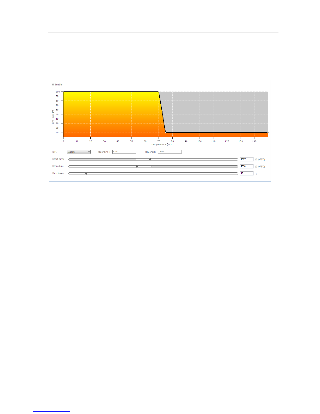
Use this feature to regulate lamp power when the LED module gets too hot. At a
certain temperature the lamp starts to dim in order to control temperature. At a
critical temperature level the lamp will switch off completely.
Usage
Select the Enable check box to use this feature. Drag the points or the lines in the
resulting graph to adjust the configuration. Alternatively, use the sliders to changes
values directly. Based on the device model, the feature is shown in either temperature
(degrees Celsius) or resistance values (in Ohm).
NOTE: For a detailed technical description of the characteristics of the device model,
like constraints and limitations, please refer to Device-specific technical description.
Page 52
User Manual Philips MultiOne
© Philips Lighting B.V. 2014 Page 52 / 81
12.3.26 Quick Lamp Start
Product group
FLUO
Description
When the Enable check box is selected, the lamp can be switched on immediately
without the necessity for preheating the lamp. The preheat sequence (typically
between 0.6 seconds and 1.0 seconds) will thus be skipped. This is possible because
heating of the electrodes is not turned off.
Usage
Select the Enable check box to use this feature.
12.3.27 Touch and Dim
Product group
FLUO, LED
Description
This feature defines the startup behavior of a touch and dim controlled device after a
power failure during dimming.
Usage
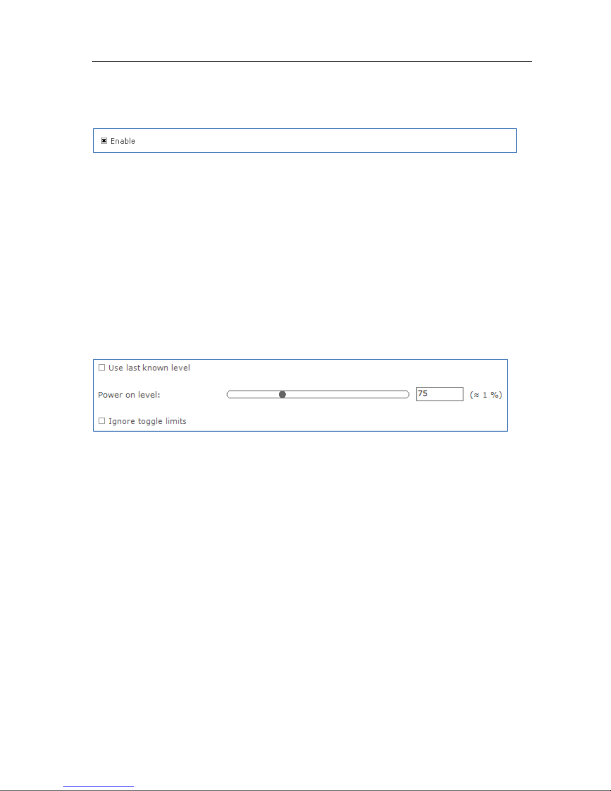
When the Use last known level check box is selected, the device will start up at the
last known dim level that was used during dimming.
If this is not checked the power on level can be configured between 0 and 100% of
the light.
When the Ignore toggle limits check box is selected, the normal toggle limits are
ignored and dimming starts directly.
If this is not checked the normal toggle limits are used.
Page 53
User Manual Philips MultiOne
© Philips Lighting B.V. 2014 Page 53 / 81
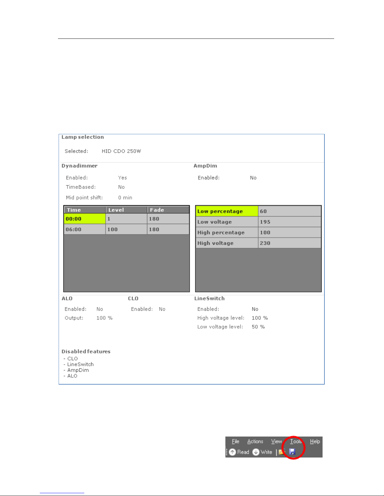
12.4 Using the features summary
For most devices an additional tab is shown on the Device features tab, called
Summary. The Summary tab gives a compact overview of the settings that have
been entered for all the features of this device. As the features are different per
product group, the summary is also different. The features cannot be changed on the
Summary tab.
12.5 Saving and opening a feature configuration file
To save and open a feature configuration file, the Device features tab must be active.
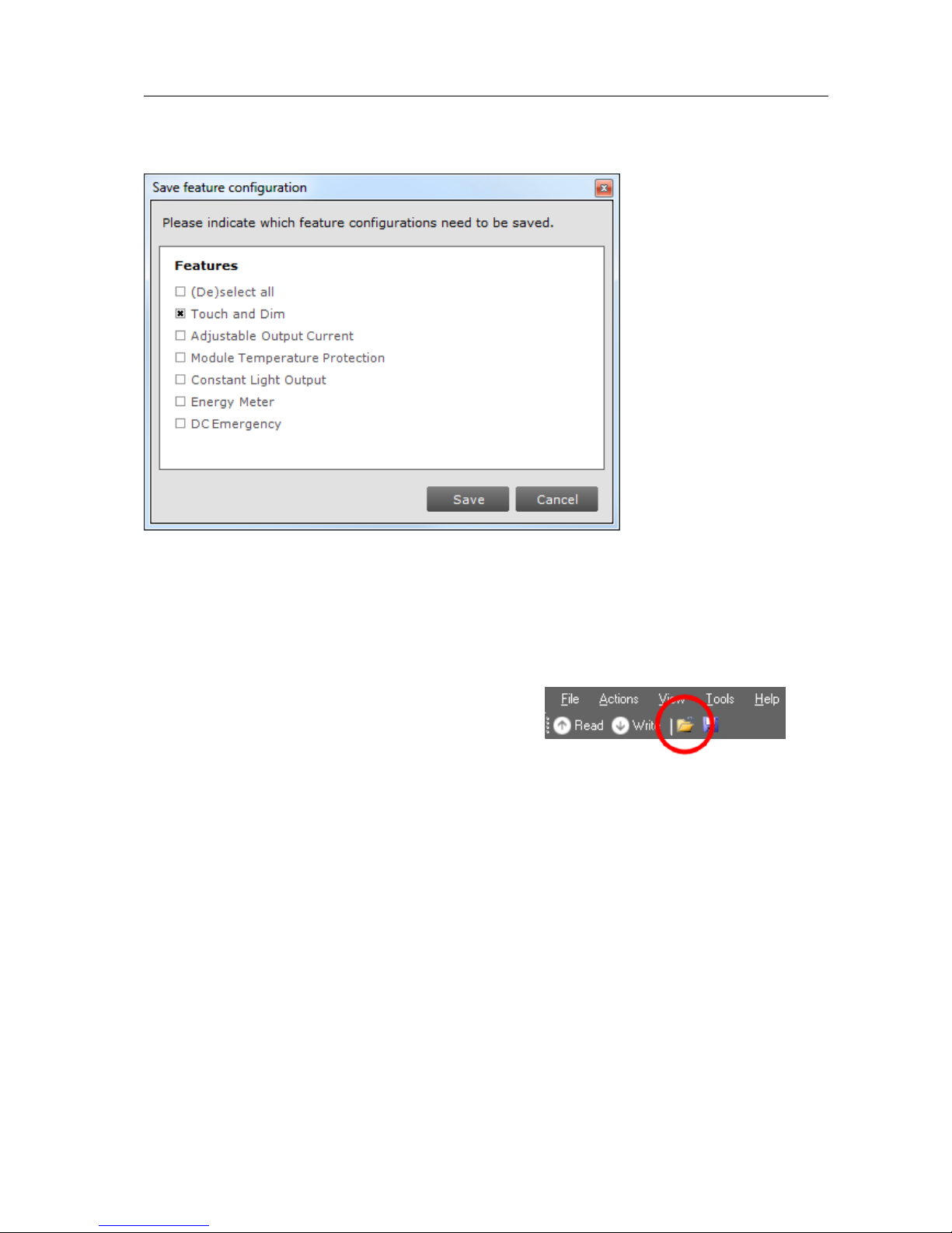
Feature configurations can be saved to a file for later use. To do so, first select the
Device features tab to make feature configurations
Page 54
User Manual Philips MultiOne
© Philips Lighting B.V. 2014 Page 54 / 81
for the selected device. Then, click the disk icon on the toolbar or select File Save
as. A dialog window pops up that lists the features of the device:
Select any number of features and click Save. The save file dialog window appears.
Choose a location and a file name and click Save. The selected features will now be
written to the file.
To open a feature configuration file, click the folder icon on the toolbar or select File
Open. The open file dialog window appears.
Select a file and click Open. The contents of the
Device features tab are updated to show the
information that was read from the file.
Only feature configurations are stored in the file. This means that a file made for a
certain device can be read into the Device features tab for a different device.
MultiOne attempts to read as many feature configurations as possible.
Example: a feature configuration file exists that was made for device D1, which has
features AOC, CLO and MTP. A different device, D2, has features AOC, Energy Meter
and Touch and Dim. When opening the feature configuration file for device D1 while
device D2 is selected, only the configuration for feature AOC will be read, since
features CLO and MTP are not supported by device D2.
Feature configuration files can be distributed to other users of MultiOne. A typical
example is that one user prepares a feature configuration file, and then sends it to
another user who uses MultiOne Basic. This user then opens the file and configures
the connected device.
Page 55

User Manual Philips MultiOne
© Philips Lighting B.V. 2014 Page 55 / 81
12.6 Configuring a single device
There are situations in which only one device will be configured at the time. In this
case it is not necessary to have the full functionality of the Network, including Scan
and Commission buttons. To optimize the workflow for single device configuration,
select Single device programming in the Application Mode Selector.
When Single device programming has been selected, MultiOne will automatically
scan the DALI network and select the connected device for communication. In this
mode, the Network panel is collapsed by default. If multiple devices have been
found, MultiOne will show a message and switch to regular configuring mode.
12.7 Configuring multiple DALI devices (simultaneously)
There are situations in which multiple devices need to be configured at the same
time. The procedure to simultaneously configure multiple devices of the SAME TYPE
AND VERSION is as follows (Note: this method will not work with MultiOne Basic):
1. Connect maximum 64 devices of the SAME TYPE AND VERSION, in parallel to
the DALI connectors of the USB2DALI interface
2. Connect the USB2DALI interface to the USB port (both black and red USB
plugs (USB-A)).
3. Connect the devices to the mains.
4. Start MultiOne
5. Choose Tools Preferences
6. Clear the Write & verify checkbox and click OK
7. Click the Commission button on the Network panel to start commissioning.
8. Choose Actions Add virtual device.
9. Select the device of the same type and version as the ones connected on the
Network panel.
10. Select the Device features tab
11. Change any of the features.
12. Click Write on the toolbar.
Note: There will not be an individual confirmation for every device. So if any of
them failed to be configured, it is not known which one.
Note: Remember that applications can be affected by the availability of the short
address.
Page 56

User Manual Philips MultiOne
© Philips Lighting B.V. 2014 Page 56 / 81
12.8 Configuring multiple DALI devices (consecutively)
There are situations in which multiple devices need to be configured one after
another. The procedure to consecutively configure multiple devices of the SAME TYPE
AND VERSION differs slightly between MultiOne Basic and MultiOne (full version).
12.8.1 MultiOne Basic
1. Connect one device
2. Connect the USB2DALI interface to the USB port (both black and red USB
plugs (USB-A))
3. Connect the device to the mains
4. Start MultiOne
5. If needed, select All in the Application mode selector
6. Click Scan network in the Network panel to start scanning
7. Select FileOpen to open the required feature configuration file
8. Select the Commands tab
9. At Data field, enter 255; click the Short Addr button. (See NOTE!)
This removes the short address; in the network the short address is shown as
‘broadcast’
10. Select the Device features tab
11. Click Write on the toolbar
12. Replace device
13. Click Write on the toolbar
14. Replace device
15. Etc.
12.8.2 MultiOne (full version)
1. Connect one device
2. Connect the USB2DALI interface to the USB port (both black and red USB
plugs (USB-A))
3. Connect the device to the mains
4. Start MultiOne
5. If needed, select All in the Application mode selector
6. Click Scan network in the Network panel to start scanning
7. Select FileOpen to open the required feature configuration file
8. Right click the device in the Network panel and select Reset short address
9. Select the Device features tab
10. Click Write on the toolbar
11. Replace device
12. Click Write on the toolbar
Page 57
User Manual Philips MultiOne
© Philips Lighting B.V. 2014 Page 57 / 81
13. Replace device
14. Etc.
Note: Remember that applications can be affected by the removal of the short
address.
12.9 Offline feature configuration preparation
When a device or network is not present, it is still possible to prepare a feature
configuration. This might be useful when you would like to prepare a feature
configuration file that can be read at a later time, and written to the device when it is
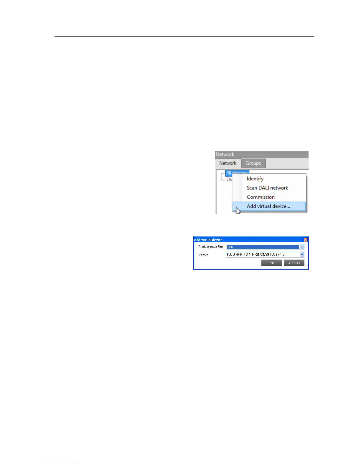
connected. To make a configuration you need to add one or more virtual devices.
To add a virtual device, right-click All devices in the
Network and choose Add virtual device.
Alternatively choose Actions Add virtual device.
A dialog window pops up that lists all devices
supported by MultiOne. Make a selection and click
OK. An item called Virtual devices appears in the
Network. Expand it by clicking the + sign to see the
list of virtual devices. Note that virtual devices do
not have a short address and MultiOne will show Broadcast on the location of the
short address. Virtual devices can only be
addressed using broadcast commands.
Select a virtual device and select the Device
features tab. The device features are shown
as if the device was physically connected. Configure the features as desired, and then
save the feature configuration to a file. You have now made a feature configuration
file without being connected a device.
12.10 Accessing diagnostics
Some devices from the product groups HID, LED and CONTROL support diagnostics.
To access these diagnostics, select a device in the Network and select the
Diagnostics tab. Upon clicking Read on the toolbar, the device’s diagnostics
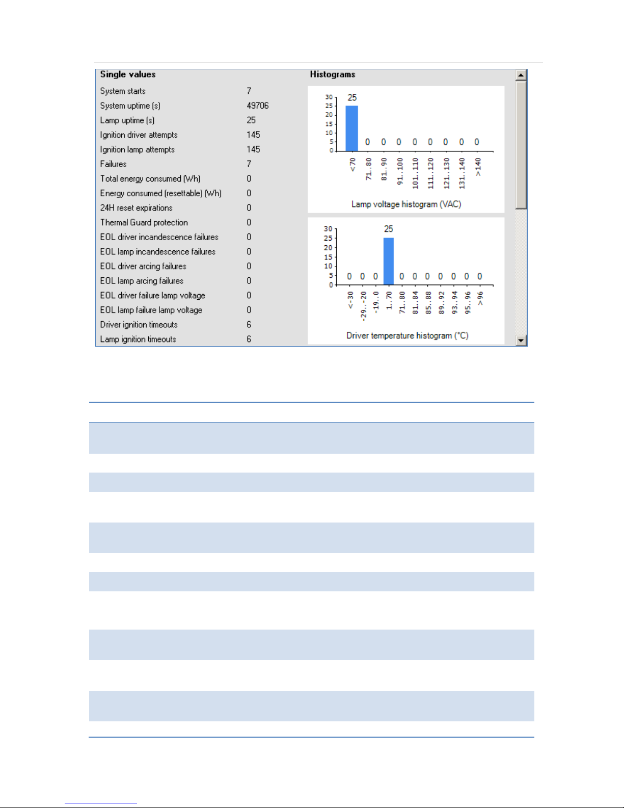
information will be read and displayed. Diagnostics for a HID device might look as
follows:
Page 58
User Manual Philips MultiOne
© Philips Lighting B.V. 2014 Page 58 / 81
A brief explanation of all HID diagnostics is given below.
Table 1 HID diagnostics
Diagnostic
Description
System starts
Number of times the HID driver was switched on (via
the mains).
System uptime (s)
Total time the HID driver was on.
Lamp uptime (s)
Total lamp burning time.
Ignition driver attempts
Number of times the HID driver attempted to ignite a
lamp.
Ignition lamp attempts
Number of times the HID driver attempted to ignite
the lamp, since last lamp replacement a).
Failures
Total number of failures detected by the HID driver.
Total energy consumed
Total energy consumed by the HID driver.
Energy consumed
(resettable) (Wh)
Energy consumed since last user-reset.
24H reset expirations
HID driver was operating for more than 24 hours; any
failures blocking driver to operate the lamp are cleared
Thermal Guard Protection
Thermal Guard activated as a consequence of high
temperature level.
EOL driver incandescence
failures
End-Of-Life situation showing incandescent mode of
operation of the lamp.
EOL lamp incandescence
End-Of-Life situation showing incandescent mode of
Page 59

User Manual Philips MultiOne
© Philips Lighting B.V. 2014 Page 59 / 81
failures
operation of the lamp, since last lamp replacement a).
EOL driver arcing failures
End-Of-Life situation showing an arcing mode of
operation of the lamp.
EOL lamp arcing failures
End-Of-Life situation showing an arcing mode of
operation of the lamp, since last lamp replacement a).
EOL driver failure lamp
voltage
End-Of-Life situation showing a lamp voltage level that
was out of operating range.
EOL lamp failure Lamp
voltage
End-Of-Life situation showing a lamp voltage level that
was out of operating range, since last lamp
replacement a).
Driver ignition timeouts
Failed to successfully ignite the lamp.
Lamp ignition timeouts
Failed to successfully ignite the lamp, since last lamp
replacement a).
Cycling driver failures
Cycling of the lamp (extinguished for more than N
times subsequently) [where N depends on lamp type].
Cycling lamp failures
Cycling of the lamp (extinguished for more than N
times subsequently), since last lamp replacement
[where N depends on lamp type] a).
Extinguished failures driver
Detection of an extinguished lamp.
Extinguished failures lamp
Detection of an extinguished lamp, since last lamp
replacement a).
Mains high failures
Mains voltage level detected that was too high to
continue operation.
Mains low failures
Mains voltage level detected that was too low to
continue operation.
Bus failures
Bus voltage level detected that was out of operating
range.
Vmid failures
Midpoint voltage level detected that was out of
operating range.
Short circuits
Short circuit detected in the lamp connection.
ZCD failures
Critical failure detected in lamp or driver.
Over Power Protection
failures
Over power detected.
Invalid lamp table failures
HID driver switched-on with a non-supported or
corrupt lamp table selected.
a) lamp replacement trigge rs an erase of predefined lamp -specific items such as ignition atte mpts, lamp errors.
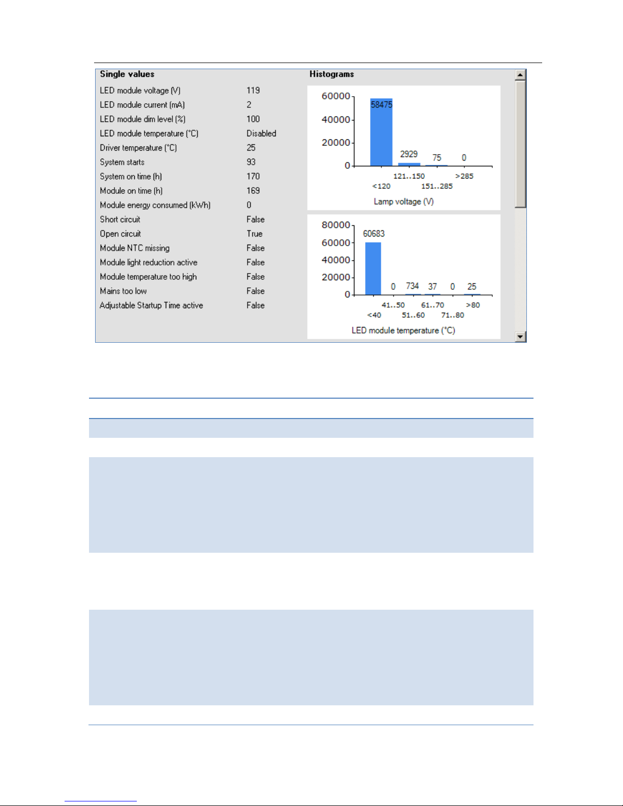
Diagnostics for a LED device might look as follows:
Page 60
User Manual Philips MultiOne
© Philips Lighting B.V. 2014 Page 60 / 81
A brief explanation of all LED diagnostics is given below.
Table 2 LED diagnostics
Diagnostic
Description
LED module voltage (V)
Represents the output LED module voltage.
LED module current (mA)
Represents the output LED module current
LED module dim level (%)
Represents the current dim level set by the LED
driver. Takes into account all factors that can
influence dimming like Constant Light Output,
Module Temperature Protection, all dimming
interfaces etc.
LED module temperature (ºC)
Represents the LED module temperature. Available
only when Module Temperature Protection is
selected and an NTC value is selected.
Driver temperature (ºC)
Represents the internal driver temperature. It does
not represent T
case
of the driver. Though there is a
correlation between T
case
and internal driver
temperature, the difference can vary depending on
current setting of driver.
System starts
Represents the number of times the LED driver is
Page 61

User Manual Philips MultiOne
© Philips Lighting B.V. 2014 Page 61 / 81
powered ON.
System on time (h)
Represents the hours the LED driver is ON. (LED
module is OFF)
Module on time (h)
Represents the number of hours the LED module is
powered ON.
Module energy consumed
Represents the energy consumed by LED module
alone. Only output parameters (LED module voltage
and current) are used to calculate energy. The LED
driver energy consumption is not accounted. Hence it
does not represent true input energy consumption
of the LED system.
Short circuit
This indicates if output LED module is shorted.
Open circuit
This indicates if output LED module is open or not
connected to LED driver
Module NTC missing
This indicates missing NTC on the LED module.
Available only when Module Temperature Protection
is selected and 10k NTC is selected. Missing NTC flag
will not be activated if 15k+390 Ω NTC is selected.
Module temperature
reduction active
This indicates light level reduction due to module
temperature being active.
Module temperature too
high
This indicates whether the LED module temperature
exceeds 90 ºC causing module to turn OFF.
Mains too low
This indicates that the LED driver is not operating
since input voltage at power ON is too low.
Adjustable Startup Time
active
This indicates that the LED driver is in the startup
phase as defined by the Adjustable Startup Time. For
example if the Adjustable Startup Time is set to
20000 ms, and the diagnostic information is read at
startup within 20 s, this check box will be selected
indicating startup condition.
12.11 Sending DALI commands
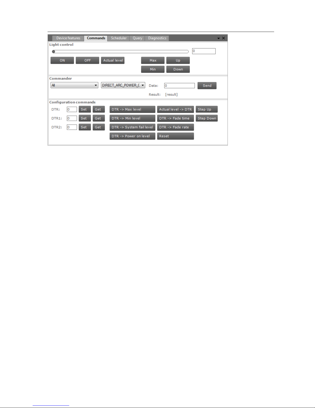
To manually send DALI commands select the Commands tab.
Page 62
User Manual Philips MultiOne
© Philips Lighting B.V. 2014 Page 62 / 81
The Commands tab has the following panes:
Light control
Commander
Configuration commands
Light control
This pane offers a number of buttons to immediately influence the behavior of the
device. These controls are useful when quick feedback in terms of light is desired.
Commander
To send a DALI command as a broadcast command, first select All devices in the
Network, then select the DALI command in the Commander pane and finally click
the Send button. To send a DALI command to a specific address or group, select the
corresponding device or group in the Network.
Configuration commands
To manually set or get the so-called DTR (Data Transfer Register) values of the device,
use the buttons in the left part of this pane.
To use the actual DTR value of the device with a number of DALI commands, use the
buttons in the right part of this pane. Besides a number of DALI commands using the
DTR value, also Reset, Step Up and Step Down are direct available.
12.12 Querying devices
To automatically execute a number of standard DALI query commands select the
Query tab.
Page 63
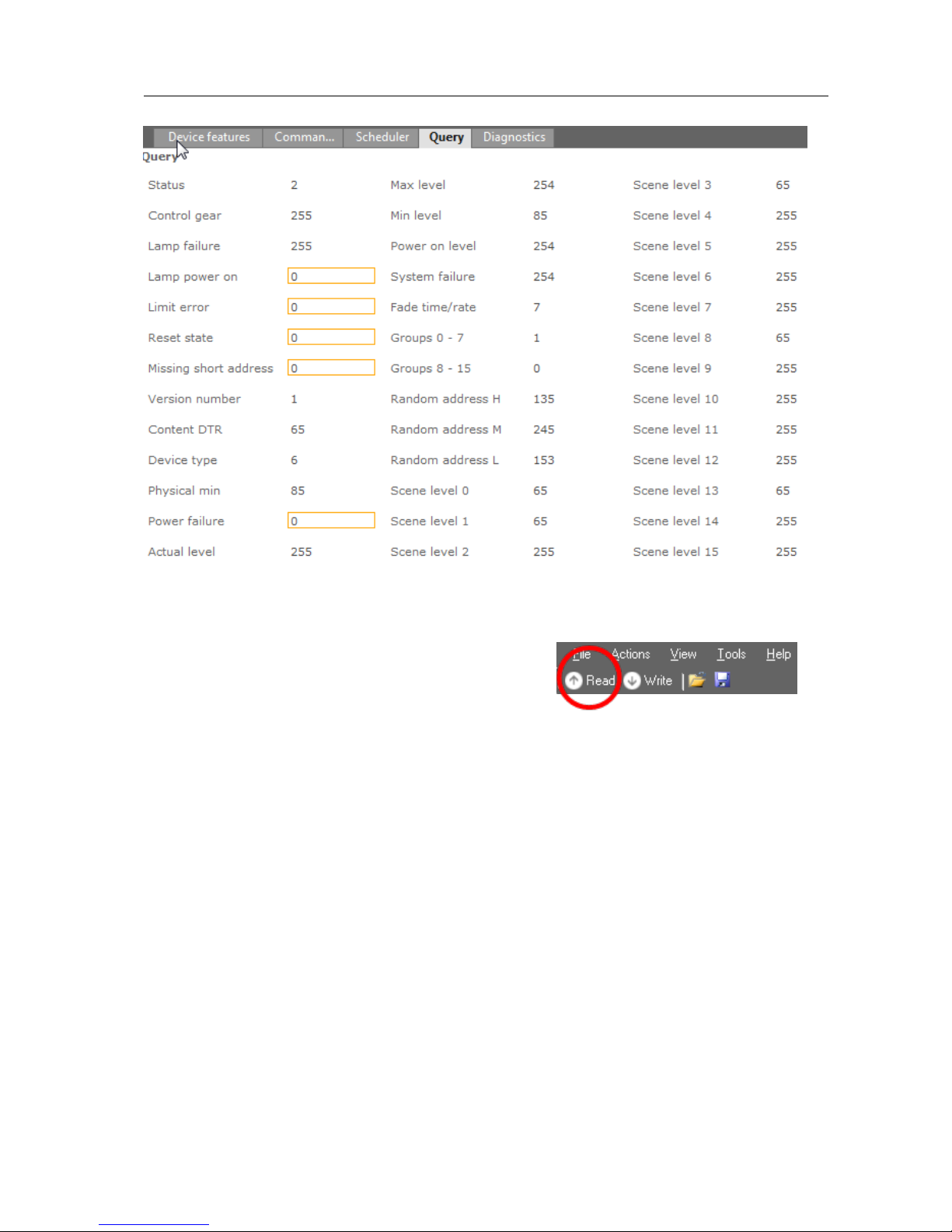
User Manual Philips MultiOne
© Philips Lighting B.V. 2014 Page 63 / 81
To make sure that the information in the Query tab
corresponds to the selected device, click Read on
the toolbar.
12.13 Working with DALI command scripts
To run a series of DALI commands, a script can be created in the Scheduler tab. This
script can be executed any number of times. Furthermore it is possible to save the
script to a file for easy reuse.
Page 64
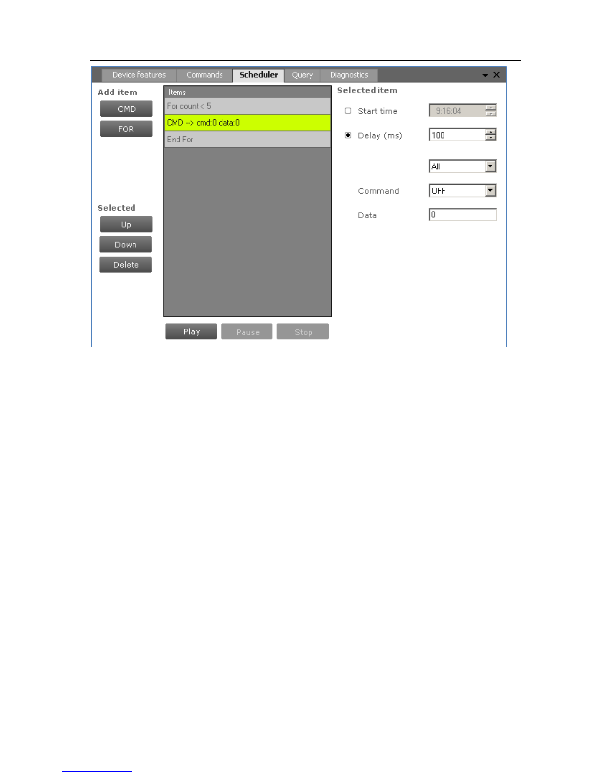
User Manual Philips MultiOne
© Philips Lighting B.V. 2014 Page 64 / 81
The Scheduler tab has the following panes:
Add item
o A CMD button to insert DALI commands
o A FOR button to insert a loop, consisting of a FOR and an END FOR
Selected, containing buttons to work with (Up, Down, Delete) the currently
selected item in the schedule
Items, representing the schedule
Selected item, the settings of the currently selected item
Schedule playback buttons (Play, Pause, Stop)
To add a command to the schedule, click the CMD button. The command is added to
the schedule and it is automatically highlighted. On the Selected item pane, choose
the desired DALI command and settings. By selecting the Start time check box and
providing a time, this command will be sent at an exact moment in time.
Alternatively, commands can be sent relative to each other. Select the Delay check
box and provide a value in milliseconds to do so. Then, select which DALI command
will be sent by using the two drop down boxes; the first selects the command group
and the second selects the actual command. If a command parameter is required,
enter it into the Data field.
Page 65
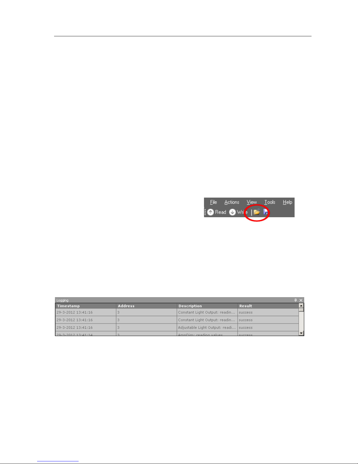
User Manual Philips MultiOne
© Philips Lighting B.V. 2014 Page 65 / 81
By repeatedly clicking the CMD button, a series of DALI commands can be created.
Each command has its own settings.
A schedule can also contain loops. A loop has a FOR-item, one or more commands,
and finally an END FOR-item to mark the end of the loop. Click the FOR button to
create a loop. By default, the loop will run infinitely (that is, until schedule playback is
manually stopped or paused by clicking Stop or Pause). To change the number of
times the loop will be executed, select the FOR-item and enter a value for Maximum
count on the Selected item pane.
To rearrange the schedule, select a command and use the Up and Down buttons to
move this up or down respectively. Delete a command by clicking the Delete button.
To start, pause, or stop a schedule playback, use the Play, Pause and Stop buttons.
To save a schedule to file for later use, click the disk icon on the toolbar. Alternatively,
select File Save or File Save As. Choose a location, a filename and click Save.
The schedule has now been saved.
To open a previously stored schedule, click the
folder icon on the toolbar. Alternatively, select
File Open. Choose a schedule file and click Open. The Scheduler tab now shows
the schedule from the file.
12.14 The logging window
The logging window shows the communication related to the features currently
being read or written or when DALI commands are sent or received through the
USB2DALI interface.
Timestamp
The time the feature was read or written or the time the command was sent. The
format of the timestamp is: <date> <time>.
Address
The short address to which the feature or command was sent. In case Broadcast is
mentioned, all devices are addressed.
Description
Page 66

User Manual Philips MultiOne
© Philips Lighting B.V. 2014 Page 66 / 81
The name of the feature or the actual DALI command.
Result
Result of the communication.
Page 67
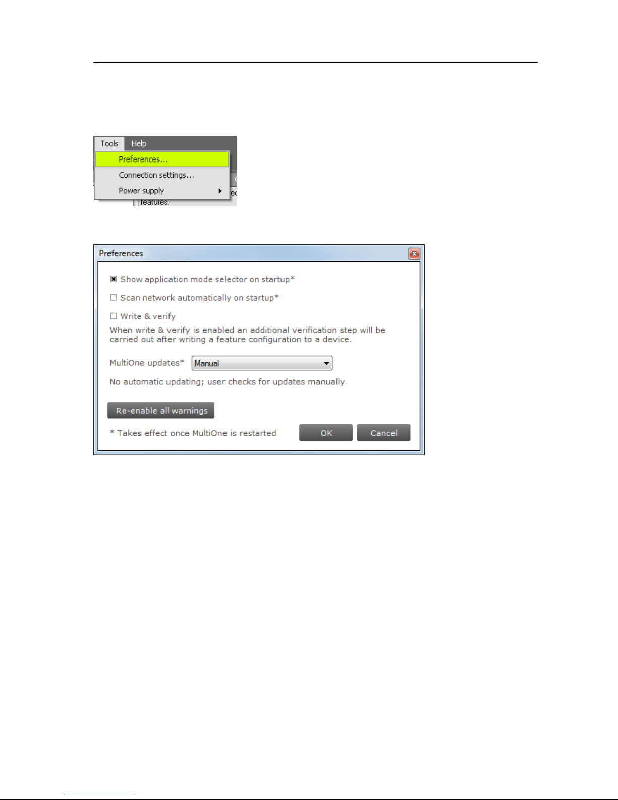
User Manual Philips MultiOne
© Philips Lighting B.V. 2014 Page 67 / 81
12.15 Setting preferences
MultiOne has a preferences window that allows you to customize the way MultiOne
works. To access the preferences window select Tools Preferences.
The Preferences window that pops up allows you to set MultiOne preferences.
The following list summarizes the available preferences and gives an explanation for
each.
Show application mode selector on startup. When MultiOne is started you
are presented with a screen that allows you choose an application mode,
based on the tasks you would like to perform. You can disable this screen by
clearing the Show application mode selector on startup checkbox. Changing
this settings only takes effect one MultiOne is restarted.
Scan network automatically on startup. By checking this checkbox MultiOne
will automatically initiate a network scan on startup. Changing this settings
only takes effect one MultiOne is restarted.
Write & verify. By default, MultiOne will write parameters to the connected
device(s) without checking the state of the device afterwards. By enabling
Write & verify you force MultiOne to perform an additional verification step
by reading back the written parameters immediately after writing. If the
Page 68
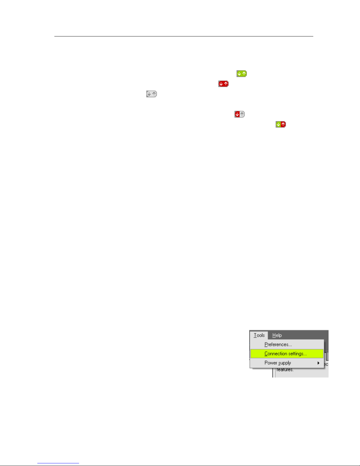
User Manual Philips MultiOne
© Philips Lighting B.V. 2014 Page 68 / 81
received values differ from the parameters that were written, MultiOne will
alert you that there is a deviation between MultiOne and the device.
The Write & verify uses different status icons then Write. When a Write &
verify action is successful the icon will be totally green . When the verify
action has failed the entire icon will become red. A pending action will be
displayed is a grey icon. It is also possible that a part of the Write &
verify fails. To help indicate where the action failed, two extra icons exist. If the
first half of the icon is red and the second part is grey, then the write
action failed. When the first part is green and the second part is red, then
the read action has failed.
MultiOne updates. Changing this setting allows the user to control the
update method of MultiOne. The following options are possible:
Automatic – Check, download, install: MultiOne will automatically check for
updates and if available download and install them automatically.
Automatic – Check, download only: MultiOne will automatically check for
updates and if available download them. The user then has to agree to let
MultiOne update itself.
Automatic - Check only: MultiOne will automatically check for updates and
notify the user if a new version is available. The user can then allow MultiOne
to download and install the update.
Manual: MultiOne will do nothing and the user has to force MultiOne to
check, download and install any update.
Re-enable all warnings. MultiOne produces a number of warnings that you
can disable by checking their Don’t show this message again checkbox. If
you would like to reset all suppressed warnings click the Re-enable all
warnings button.
12.16 Manually selecting the USB2DALI interface
MultiOne will automatically detect the USB2DALI interface that is
connected to the PC. However when multiple interfaces are
connected it will use the interface on the port that is found first.
It is possible to manually change the port that is used by
selecting Tools Connection settings.
Page 69
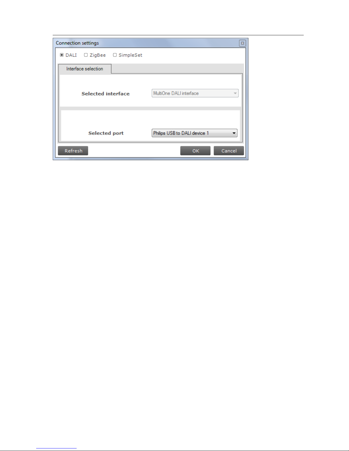
User Manual Philips MultiOne
© Philips Lighting B.V. 2014 Page 69 / 81
In the pop-up window it is then possible to select the desired port.
Page 70
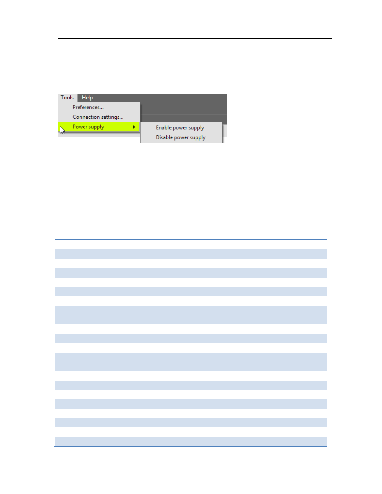
User Manual Philips MultiOne
© Philips Lighting B.V. 2014 Page 70 / 81
12.17 Enabling/Disabling the power supply of the USB2DALI interface
The USB2DALI interface will automatically detect if the DALI bus is powered by
another device (for example a DALI power supply). If the DALI network is not
powered, it will use its internal power supply.
If, during operation, the DALI network is changed in a way that it requires the
USB2DALI interface to switch on or off its internal power supply, you can do so using
the option Tools Power supply.
12.18 Supported features
The table below gives an overview of all features that are supported by MultiOne and
to which product groups they apply.
Table 3 Supported features
Device feature
Product group
LED
HID
FLUO
CONTROL
Indoor
Outdoor
1-10V min dim level
x
ActiLume General
x
ActiLume Mode
x
ActiLume Scene
x
ActiLume Wireless
General
x
ActiLume Wireless Mode
x
Active Cooling
x
Adjustable Light Output
x
Adjustable Output
Current
x x
Adjustable Startup Time
x
AmpDim
x x
Constant Light Output
x x x
Corridor Mode
x x
Dimming Interface
x x
Dynadimmer
x x
DC Emergency
x
End Of Life indication
x
Page 71

User Manual Philips MultiOne
© Philips Lighting B.V. 2014 Page 71 / 81
Energy Meter
x x
Lamp Burn-in
x
Lamp Selection
x x
Light Source Operating
Hours
x
LineSwitch
x x
LumiStep
x
Min Dim Level
x
Module Temperature
Protection
x x
Quick Lamp Start
x
Summary
x x x x
Touch and Dim
x x
12.19 Device-specific technical descriptions
For a detailed technical description of the characteristics of the devices, please visit
the product-specific Philips web sites:
Table 4 Product-specific Philips web sites
Product group
Visit:
LED
www.philips.com/Xitanium
HID
www.philips.com/Xtreme
FLUO
www.philips.com/HFR-Intelligent
CONTROL
www.philips.com/Actilume
12.20 Error handling
12.20.1 Reporting and correction of errors/warnings when reading from a
feature configuration file
When, after opening a feature configuration file, incorrect parameters are detected,
MultiOne tries to correct these parameters for the selected (virtual) device. When a
correction is made, a red border will be shown. In cases when no logical correction
can be made, an orange border will be shown.
12.20.2 Reporting of errors when reading from a device
When after reading from a device a mismatch is signaled between the parameters of
the device and MultiOne, MultiOne will not correct the parameters, but will show a
red border.
12.20.3 Reporting of errors when entering incorrect values in a feature
Entering an incorrect value for a parameter will be indicated by a red border.
Page 72
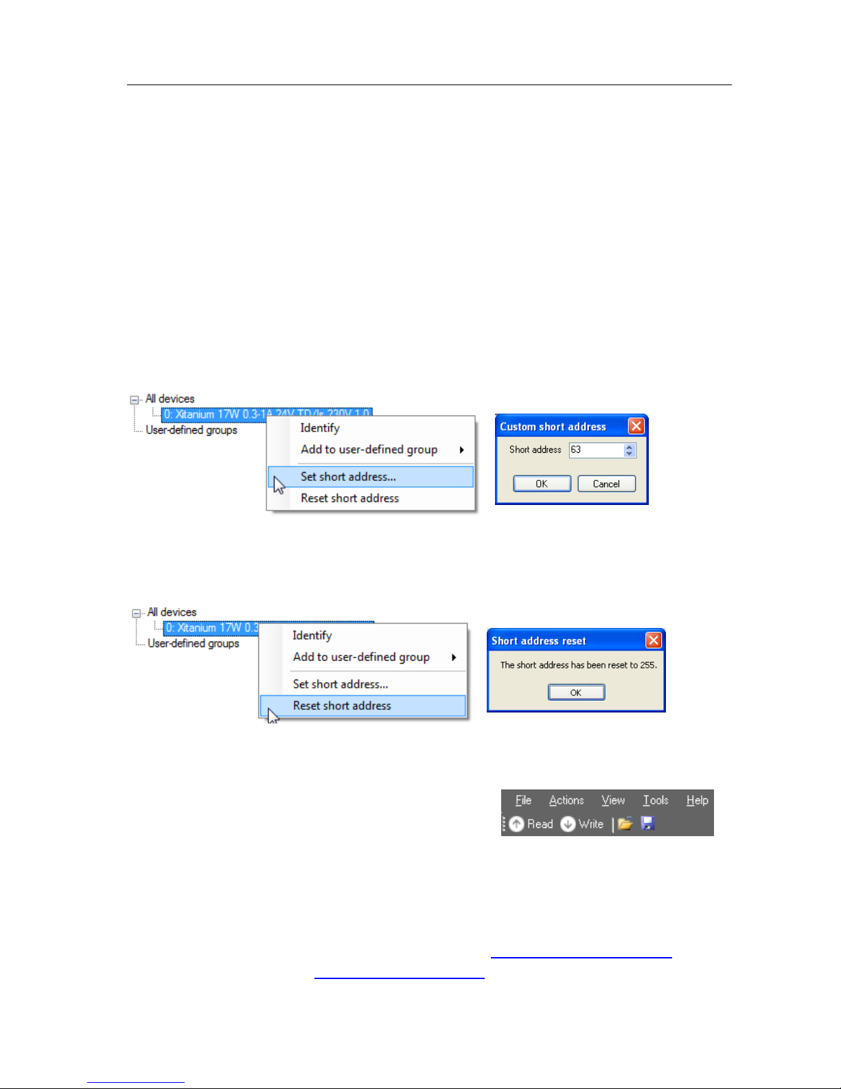
User Manual Philips MultiOne
© Philips Lighting B.V. 2014 Page 72 / 81
12.21 Troubleshooting
Problem: After starting MultiOne, no devices are displayed.
Solution: Click the Scan network button on the Network panel to start discovering
the devices in the network. If the devices connected have already a DALI short
address this will not be changed. Devices without a short address will be
programmed with a short address. When the Commission button is clicked, the short
addresses of all connected devices will be renewed, whether they already had a short
address or not.
Problem: I would like to assign a specific short address to a device.
Solution: First scan the network for devices. Right-click the device you would like to
give a short address and select Set short address. A dialog window will appear in
which you can enter the desired short address. Click OK to program the short address
into the device.
Problem: I would like to remove the short address of a device.
Solution: First scan the network for devices. Right-click the device whose short
address you would like to remove and select Reset short address. You will be
informed that the short address was reset.
Problem: I would like to configure the special features of the connected device.
Solution: After scanning the network for devices, a device has to be selected by
clicking it in the Network. Select the Device
features tab. The related features will appear. To
update the view to the actual status of the features,
click Read on the toolbar. If you now change any of the features, and want this to be
stored into the device, click Write on the toolbar.
Problem: I would like to know more technical details of a device.
Solution: Please refer to the Philips website for more detailed information
For LED driver, both indoor and outdoor, visit: www.philips.com/Xitanium
For HID drivers visit: www.philips.com/Xtreme
Page 73

User Manual Philips MultiOne
© Philips Lighting B.V. 2014 Page 73 / 81
For FLUO drivers visit: www.philips.com/HFR-Intelligent
For controls visit: www.philips.com/Actilume
Page 74
User Manual Philips MultiOne
© Philips Lighting B.V. 2014 Page 74 / 81
13 Keyboard shortcuts
Keyboard shortcuts can make it easier to work with MultiOne without using the
mouse.
USB2DALI interface
USB2ZigBee interface
The File menu
Working with feature configuration files
Ctrl+O
Open a feature configuration
file
Not supported
Ctrl+S
Save a feature configuration
file (Save)
Not supported
Ctrl+Shift+S
Save a feature configuration
file
(Save As)
Not supported
Alt+F4
Exit MultiOne
The Action menu
Working with devices
Ctrl+D
Scan network
Scan area
Ctrl+Q
Commission
Not supported
Ctrl+R
Read from current device
Not supported
Ctrl+W
Write to current device
Not supported
The Tools menu
Ctrl+M
Open the Application mode selector
The Help menu
Shift+F1
Open the Getting started document
F1
Open the User manual
Page 75
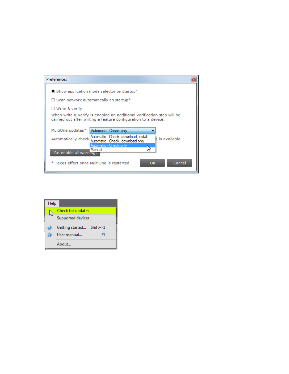
User Manual Philips MultiOne
© Philips Lighting B.V. 2014 Page 75 / 81
14 Software Update
MultiOne has the possibility to update itself to a newer version. This can be done
either automatically or manually and can be set in the preference window, see the
Setting Preferences for more info.
If the preference is set to Manual then the user can check for an update on MultiOne
by selecting Help Check for updates option.
Page 76
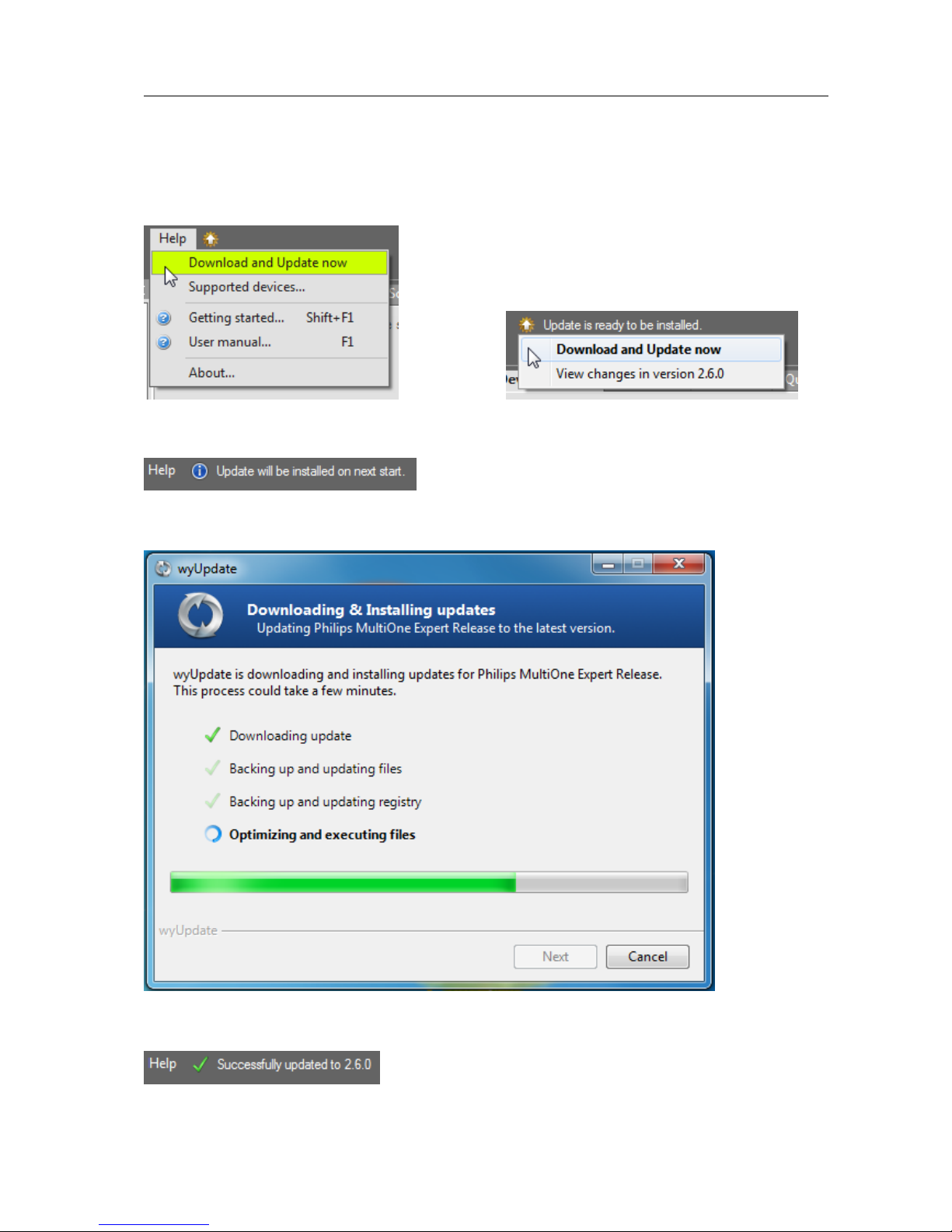
User Manual Philips MultiOne
© Philips Lighting B.V. 2014 Page 76 / 81
After a manual update check, or by using the automatic options, the update status
near the Help menu will show if a new version is available. The user can then decide
to continue downloading/updating by either using the update status or the Help
menu to carry on.
After downloading the update status will inform the user to restart to continue.
Restarting MultiOne will install the update.
A successful update of MultiOne will be shown in the update status.
Page 77

User Manual Philips MultiOne
© Philips Lighting B.V. 2014 Page 77 / 81
15 Copyright
Copyright © 2014 by Philips Lighting B.V.
All rights reserved. No part of this publication may be reproduced, transmitted,
transcribed, stored in a retrieval system or translated into any language or computer
language, in any form or by any means, electronic, mechanical, magnetic, optical,
chemical, manual or otherwise, without prior written permission from Philips. Brands
and product names are trademarks or registered trademarks of their respective
companies.
Page 78

User Manual Philips MultiOne
© Philips Lighting B.V. 2014 Page 78 / 81
16 Disclaimer
Philips makes no warranty of any kind with regard to this material, including, but not
limited to, the implied warranties of merchantability and fitness for a particular
purpose.
Philips assumes no responsibility for any error that may appear in this document.
Philips makes no commitment to update nor to keep current the information
contained in this document.
Page 79

User Manual Philips MultiOne
© Philips Lighting B.V. 2014 Page 79 / 81
17 Limitations of damages
The vendor will not be liable for any indirect, special, incidental or consequential
damages (including damages for loss of business, loss of profits, or the like), whether
based on breach of contract, tort (including negligence), product liability or
otherwise, even if the vendor or its representatives have been advised of the
possibility of such damages and even if a remedy set forth herein is found to have
failed its essential purpose.
Page 80

User Manual Philips MultiOne
© Philips Lighting B.V. 2014 Page 80 / 81
18 List of tables
Table 1 HID diagnostics ...................................................................................................................... 58
Table 2 LED diagnostics ...................................................................................................................... 60
Table 3 Supported features ............................................................................................................... 70
Table 4 Product-specific Philips web sites .................................................................................... 71
Page 81

User Manual Philips MultiOne
© Philips Lighting B.V. 2014 Page 81 / 81
19 Index
1-10V min dim level ....................................................................................................................... 30, 66
ActiLume General .................................................................................................................... 30, 32, 66
ActiLume Mode ................................................................................................................. 31, 32, 33, 66
ActiLume Scene ........................................................................................................................ 31, 32, 66
Active Cooling .................................................................................................................................. 33, 66
Adjustable Light Output ............................................................................................................... 34, 66
Adjustable Output Current .......................................................................................................... 34, 66
Adjustable Startup Time ........................................................................................................ 35, 58, 66
AmpDim ...................................................................................................................................... 36, 40, 66
Constant Light Output ..................................................................................... 37, 38, 44, 46, 57, 67
Corridor Mode ................................................................................................................................. 39, 67
DC Emergency ................................................................................................................................. 43, 67
Dimming Interface ......................................................................................................................... 40, 67
Dynadimmer ............................................................................................................................ 40, 41, 67
End Of Life indication ............................................................................................................. 44, 46, 67
Energy Meter ............................................................................................................................. 44, 52, 67
Lamp Burn-in .................................................................................................................................... 45, 67
Lamp Selection ......................................................................................................................... 43, 45, 67
Light Source Operating Hours ............................................................................................ 44, 46, 67
LineSwitch................................................................................................................................... 40, 46, 67
LumiStep ............................................................................................................................................ 47, 67
Min Dim Level .................................................................................................................................. 47, 67
Module Temperature Protection ................................................................................ 49, 57, 58, 67
Network ................................................. 16, 17, 21, 22, 23, 26, 27, 28, 52, 53, 54, 55, 59, 68, 69
Quick Lamp Start ............................................................................................................................ 50, 67
Summary ..................................................................................................................................... 29, 51, 67
Touch and Dim .................................................................................................................. 39, 50, 52, 67
user-defined group ................................................................................................................. 17, 18, 19
 Loading...