

Philips MRD210/37 Service Manual
CLASS 1
LASER PRODUCT
MRD210/37
©
Copyright 2003 Philips Consumer Electronics B.V. Eindhoven, The Netherlands
All rights reserved. No part of this publication may be reproduced, stored in a retrieval system or
transmitted, in any form or by any means, electronic, mechanical, photocopying, or otherwise
without the prior permission of Philips.
Published by BB-ET0322 Service Audio Printed in The Netherlands Subject to modification
GB
3139 785 30400
DVD Receiver
Version 1.0
TABLE OF CONTENTS
Page
Location of PC Boards................................................1-2
Versions Variation & Package ....................................1-2
Specifications..............................................................1-3
Measurement Setup ...................................................1-4
Service Aids ................................................................1-5
ESD & Safety Instruction............................................1-6
Setting Procedure & Repair Instructions.......................2
Disassembly Instructions & Service positions ..............3
Block & Wiring Diagram ................................................4
Key/Switch/Volume/Phone Board ................................. 5
RGB Board ....................................................................6
DVD Loader .................................................................. 7
Main Board ....................................................................8
Power Board .................................................................. 9
Mechanical Exploded View & Parts List...................... 10
Service Manual
COMPACT
DIGITAL AUDIO
Service
Service
Service
Service
Service
1-2
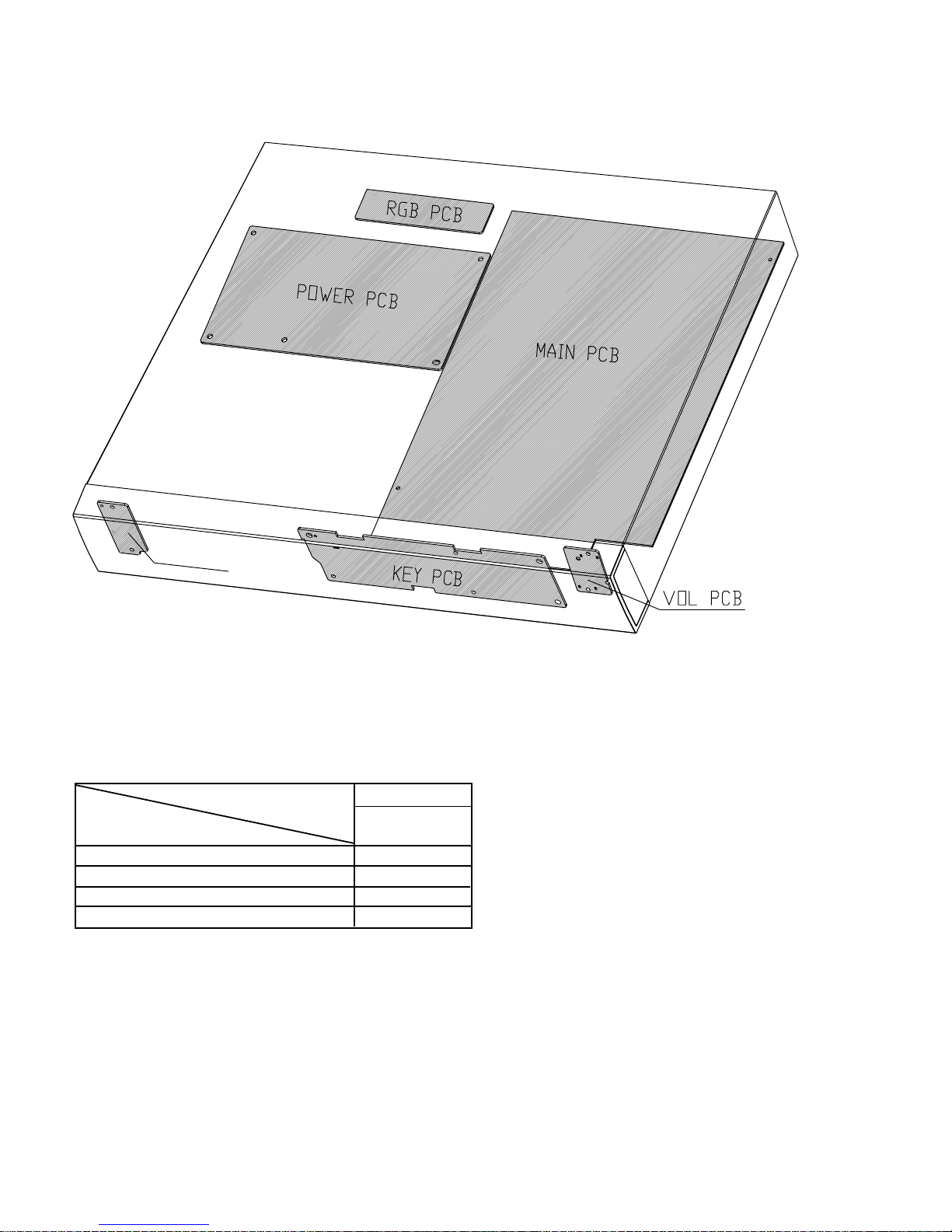
LOCATION OF PC BOARDS
POWER SWITCH PCB
VERSION VARIATION:
/37
RDS function
Progressive scan x
RGB board x
Power PCB (120V) x
Type /Versions: MRD210
Features &
Board in used

1-3
SPECIFICATIONS
AMPLIFIER SECTION
Output Power
- Stereo mode (1kHz)......................................2 x 50 W RMS
- Surround mode (1 kHz)........................50 W RMS/channel
Total Harmonic Distortion...........10 % at rated power (1 kHz)
Frequency Response .........................180 Hz-14 kHz/±1 dB
Signal-to-Noise Ratio........................................> 65dB(CCIR)
Input Sensitivity...........................................................400 mV
DVD SECTION
Laser Type......................................................Semiconductor
Disc Diameter.........................................................12cm/8cm
Video Decoding.....................................................MPEG-2
Video DAC...............................................................10 Bits
Signal System........................................................PAL/NTSC
Video Format..........................................................4:3/16:9
Video S/N......................................................56 dB(minimum)
Composite Video Output.....................................1.0Vp-p,75
Ω
S-Video Output.............................................Y - 1.0Vp-p,75Ω
..................................................................C - 0.286Vp-p,75Ω
Audio DAC....................................................24 Bits/96 kHz
Frequency Response...........................4 Hz-20 kHz (44.1kHz)
............................................................. 4 Hz-22 kHz (48 kHz)
............................................................. 4 Hz-44 kHz (96 kHz)
Digital Output.................................SPDIF Coaxial & Optical
TUNER SECTION
Tuning Range................. FM 87.5 -108 MHz (100 kHz steps)
..........................................AM 530 - 1700 kHz (10 kHz steps)
26 dB Quieting Sensitivity......................................FM 20 dB
26 dB Quieting Sensitivity..............................AM 5000 uV/m
Image Rejection Ratio...........................................FM 25 dB
................................................................................AM 28 dB
IF Rejection Ratio..................................................FM 60 dB
................................................................................AM 24 dB
Signal-to-Noise Ratio..............................................FM 60 dB
................................................................................AM 40 dB
AM Suppression Ratio...........................................FM 30 dB
Harmonic Distortion...........................................FM Mono 3%
..........................................................................FM Stereo 3%
.....................................................................................AM 5%
Frequency Response.....................FM 180 Hz-10kHz/±6 dB
Stereo Separation.........................................FM 26 dB(1 kHz)
Stereo Threshold.................................................FM 23.5 dB
MISCELLANEOUS
Power Supply Rating...........................................120V/60 Hz
Power Consumption.................................................. 160W
Dimensions (w x h x d)............... 435 mm x 78 mm x 360mm
...............................................................17.1x 3.1x 14.2 (inch)
Weight...........................................................................7.1 kg
..........................................................................15.62 pounds
IR REMOTE CONTROL
Effective Range.........................................................> 8 Meter
Number of Keys................................................................45
Battery (1.5V)............................................................AA x 2
Front Speakers / Rear(surround) speaker
System...........................................................2-way satellite
Impedance..........................................................................8Ω
Speaker drivers..................3" woofer,18mm CD dome tweeter
Dimensions (w x h x d)................... 96 mm x 155 mm x 91 mm
...................................................................3.7x 6.1x 3.5 (inch)
Weight.............................................................. 0.45 Kg/each
Center Speaker
System...........................................................2-way satellite
Impedance.........................................................................8Ω
Speaker drivers............2x 3" woofer,18mm CD dome tweeter
Dimensions (w x h x d)....................252 mm x 95 mm x 91mm
...................................................................9.8x 3.7x 3.5 (inch)
Weight....................................................................... 0.92 Kg
SUBWOOFER
System.............................................................................6.5''
Impedance......................................................................... 8Ω
Dimensions (w x h x d)............... 130 mm x 336 mm x 380mm
...............................................................5.3x 13.3x 14.8 (inch)
Weight..............................................................................8 kg
.............................................................................17.6 pounds
SPEAKERS

1-4
MEASUREMENT SETUP
FM SECTION
DISC SECTION
AC MILLIVOL TME TER
AUTO DISTORTION METER
OSCIL LOSCOPE
LOAD 4 OHM
AM-FM STEREO SIGNAL
GENERATOR
SIGNAL GENERATORAC
LOOP
AM LOOP ANT
DUT
INPUT OUTPUT
INPUT
OUTPUT
RL
AM SECTION
............
............
AC MILLIVOL TME TER
AUTO DISTORTION METER
OSCIL LOSCOPE
LOAD 4 OHM
AM-FM STEREO SIGNAL
GENERATOR
SIGNAL GENERATORAC
DUT
INPUT OUTPUT
INPUT
OUTPUT
RL
............
............
AC MILLIVOL TME TER
AUTO DISTORTION METER
OSCIL LOSCOPE
LOAD 4 OHM
DOLBY TEST METER
SIGNAL GENERATORAC
DUT
INPUT OUTPUT
INPUT
OUTPUT
............
............
AUX SECTION
.......
............
.......
............
.......
............
.......
............
AC MILLIVOL TME TER
AUTO DISTORTION METER
OSCIL LOSCOPE
LOAD 4 OHM
DUT
INPUT
............
............
.......
............
.......
............
.......
............
.......
............
DVD TEST DISC
R L C SRSLSWR L C SRSLSW
1-5
Service Tools:
Universal Torx driver holder .................................4822 395 91019
Torx bit T10 150mm ...........................................4822 395 50456
Torx driver set T6-T20 .........................................4822 395 50145
Torx driver T10 extended .....................................4822 395 50423
Compact Disc:
SBC426/426A Test disc 5 + 5A ...........................4822 397 30096
SBC442 Audio Burn-in test disc 1kHz .................4822 397 30155
SBC429 Audio Signals disc .................................4822 397 30184
Dolby Pro-logic Test Disc ....................................4822 395 10216
ESD Equipment:
Anti-static table mat - large 1200x650x1.25mm ...4822 466 10953
anti-static table mat - small 600x650x1.25mm .....4822 466 10958
Anti-static wristband ............................................4822 395 10223
Connectorbox (1MΩ) ..........................................4822 395 11307
Extension cable
(to connect wristband to conn.box) ..........4822 320 11305
Connecting cable
(to connect table mat to conn.box) ...........4822 320 11306
Earth cable (to Connect product to mat or box) --4822 320 11308
Complete kit ESD3
(combining all above products) ...............4822 320 10671
Wristband tester ...................................................4822 344 13999
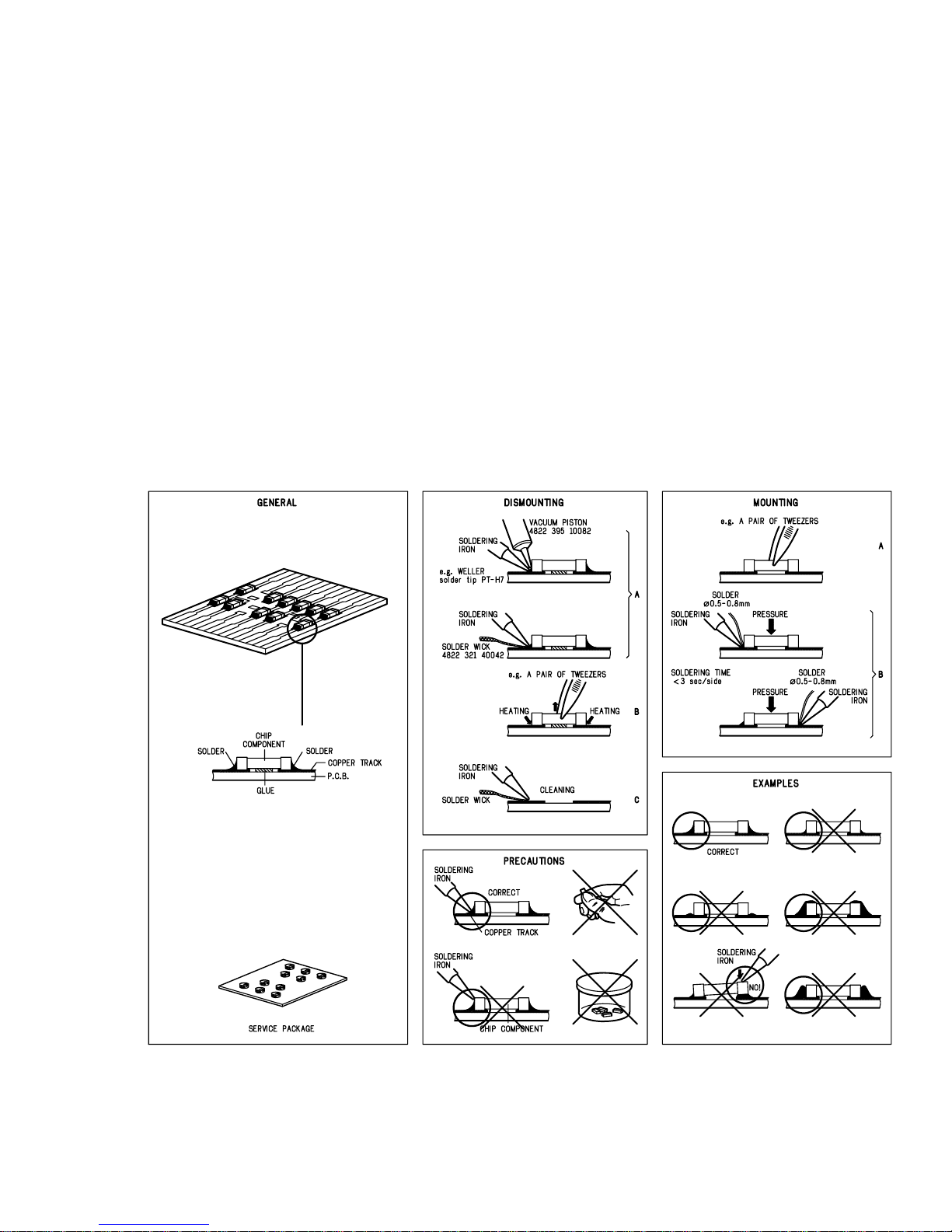
SERVICE AIDS
HANDLING CHIP COMPONENTS
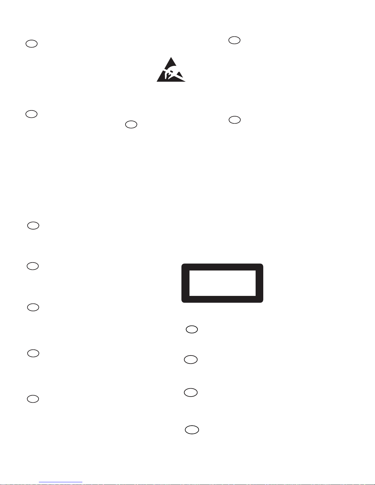
1-6
GB
WARNING
All ICs and many other semi-conductors are
susceptible to electrostatic discharges (ESD).
Careless handling during repair can reduce life
drastically.
When repairing, make sure that you are
connected with the same potential as the mass
of the set via a wrist wrap with resistance.
Keep components and tools also at this
potential.
F
ATTENTION
Tous les IC et beaucoup d’autres
semi-conducteurs sont sensibles aux
décharges statiques (ESD).
Leur longévité pourrait être considérablement
écourtée par le fait qu’aucune précaution n’est
prise à leur manipulation.
Lors de réparations, s’assurer de bien être relié
au même potentiel que la masse de l’appareil et
enfiler le bracelet serti d’une résistance de
sécurité.
Veiller à ce que les composants ainsi que les
outils que l’on utilise soient également à ce
potentiel.
ESD
D
WARNUNG
Alle ICs und viele andere Halbleiter sind
empfindlich gegenüber elektrostatischen
Entladungen (ESD).
Unsorgfältige Behandlung im Reparaturfall kan
die Lebensdauer drastisch reduzieren.
Veranlassen Sie, dass Sie im Reparaturfall über
ein Pulsarmband mit Widerstand verbunden
sind mit dem gleichen Potential wie die Masse
des Gerätes.
Bauteile und Hilfsmittel auch auf dieses gleiche
Potential halten.
NL
WAARSCHUWING
Alle IC’s en vele andere halfgeleiders zijn
gevoelig voor electrostatische ontladingen
(ESD).
Onzorgvuldig behandelen tijdens reparatie kan
de levensduur drastisch doen verminderen.
Zorg ervoor dat u tijdens reparatie via een
polsband met weerstand verbonden bent met
hetzelfde potentiaal als de massa van het
apparaat.
Houd componenten en hulpmiddelen ook op
ditzelfde potentiaal.
I
AVVERTIMENTO
Tutti IC e parecchi semi-conduttori sono
sensibili alle scariche statiche (ESD).
La loro longevità potrebbe essere fortemente
ridatta in caso di non osservazione della più
grande cauzione alla loro manipolazione.
Durante le riparazioni occorre quindi essere
collegato allo stesso potenziale che quello della
massa dell’apparecchio tramite un braccialetto
a resistenza.
Assicurarsi che i componenti e anche gli utensili
con quali si lavora siano anche a questo
potenziale.
“Pour votre sécurité, ces documents
doivent être utilisés par des spécialistes agréés, seuls habilités à réparer
votre appareil en panne”.
GB
Safety regulations require that the set be restored to its original
condition and that parts which are identical with those specified,
be used.
NL
Veiligheidsbepalingen vereisen, dat het apparaat bij reparatie in
zijn oorspronkelijke toestand wordt teruggebracht en dat onderdelen,
identiek aan de gespecificeerde, worden toegepast.
F
Les normes de sécurité exigent que l’appareil soit remis à l’état
d’origine et que soient utiliséés les piéces de rechange identiques
à celles spécifiées.
D
Bei jeder Reparatur sind die geltenden Sicherheitsvorschriften zu
beachten. Der Original zustand des Geräts darf nicht verändert werden;
für Reparaturen sind Original-Ersatzteile zu verwenden.
I
Le norme di sicurezza esigono che l’apparecchio venga rimesso
nelle condizioni originali e che siano utilizzati i pezzi di ricambio
identici a quelli specificati.
"After servicing and before returning set to customer perform a
leakage current measurement test from all exposed metal parts to
earth ground to assure no shock hazard exist. The leakage current
must not exceed 0.5mA."
CLASS 1
LASER PRODUCT
3122 110 03420
GB
Warning !
Invisible laser radiation when open.
Avoid direct exposure to beam.
S
Varning !
Osynlig laserstrålning när apparaten är öppnad och spärren
är urkopplad. Betrakta ej strålen.
SF
Varoitus !
Avatussa laitteessa ja suojalukituksen ohitettaessa olet alttiina
näkymättömälle laserisäteilylle. Älä katso säteeseen!
DK Advarse !
Usynlig laserstråling ved åbning når sikkerhedsafbrydere er
ude af funktion. Undgå udsaettelse for stråling.

1) System Reset
a) Press "SYSTEM" button on R/C. TV show "SETUP"
b) Select the menu using the " " and " " button on R/C
c) Go feature setup page to do system reset
2) Region Code Change
2-1
System, Region code, Tuner, etc. setting procedure
After replacement / repair of the MPEG board, the customer
setting and the region code may lost. Changing the Region
code will put the player back in the state which it has left the
factory.
Region Code
1 USA
2EU
3AP
4 Australia, NZ, Latam
5 RUSSIA, INDIA
6 CHINA
TV System
1 NTSC
2PAL
3 AUTO
Menu/ Audio Subtitle (AS) Language
1 English
2 English
3 English
4 English
AFS
001 LX3000D /LX3500D /MRD200
002 MX3600D /MX3800
003 LX3700D /LX3750W
005 MRD210
oem derivative
08
.
region code = 1 digit
.
tv system = 1 digit
.
"as/menu lang" = 1 digit
.
"AFS" = "architechture Feature Set" = 3 digits
This field is used to define the architecture / features sets for
each product.
.
"oem derivative" = 2 digit
This field is use to define the OEM set. This will affect the
background display.
Hence in total, reprograming will be done by way of the
remote control. It should run as below :-
a) Put the player in stop mode. No disc loaded.
b) Press the following key on remote control:
For MRD210/37 (USA) :
<PLAY> <159> <131> <005> <08> <PLAY>
∗∗
∗∗
∗ After the Region Code is changed it is necessary to reset
the system so that the new Region Code will be fully
effective. All customer setting will be lost.
∗∗
∗∗
∗ On top of the maximum number of times allowed for
changing the region code is changed to 25.
∗∗
∗∗
∗ When the counter reach 25, you will not be able to further
change the code until you reset the timer by the Region
Code timer reset procedure
3) Region code change timer reset
Press below key to reset the timer :
a) In DISC source, stop mode and no disc in tray.
b) Press R/C "Play -159-PLAY" to reset timer to 25
4) Tuner area change
a) Press the "OPEN/CLOSE" button to openthe set's door
b) Press "1" "5" "9" button by using R/C.
c) TV Show "TUNER AREA ADJUST"
d) Select the tuner area you want by using the "
" and
"
" button on R/C, then press "OK" to confirm. TV show
" TUNER AREA CHANGED"
If you didn't press it in five seconds, the system will remain
original status.
USA FM 87.5M 108M 100K
AM 530K 1700K 10K
APAC FM 87.5M 108M 50K
AM 531K 1602K 9K
EUROPE FM 87.5M 108M 50K
AM 531K 1602K 9K
LATAM FM 87.5M 108M 50K
AM 530K 1710K 10K
AUSTRALIA FM 87.5M 108M 50K
/ NZ AM 531K 1602K 9K
Note :Please refer to the above different tuner area.
AREA BAND FREQUENCY (Hz) STEP(Hz)
5. Video Out Change
a) Press "SYSTEM" on R/C button
b) Select the menu using the " " and " " button on R/C
c) Go picture setup page select Video out item.
6. Password Change
a) Press "SYSTEM" on R/C button
b) Select the menu using the "
" and " " button on R/C
c) Go feature setup page select "PASSWORD". TV show
"ENTER CODE". Press 4 times of "STOP" button on R/C.
d) Select "PARENTAL" "8 ADULT" on TV.
e) Enter PASSWORD to "1234"
∗∗
∗∗
∗ "1234" is a default password supplied.
7. Checking on the Software version
a) Open the CD door.
b) Press "123" and "OK" on the remote control.
c) TV will show the version on screen.
8. Upgrading new software
a) Open the CD-door, then insert the CD-R program disc.
b) Close the CD-door.
c) TV will show:-
.
"disc loading"
.
"bank30.rom"
.
"writing" about 6 seconds.
.
"Done"
∗ ∗
∗ ∗
∗
The latest upgraded is in version VER0523.
2-1
CAUTION !
This information is confidencial and may
not be distributed. Only a qualified service
person should reprogram the Region Code.
REPAIR INSTRUCTIONS
2-2 2-2

2-3
REPAIR INSTRUCTIONS
2-3
2-4
REPAIR INSTRUCTIONS
2-4
3-1
DISASSEMBLY INSTRUCTIONS
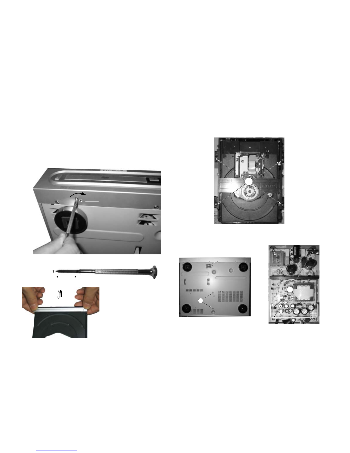
1) Open the DVD Tray by using the Open/Close Button
while the Set is ON and disconnect the mains supply after
removing the Tray Cover.
Note: If this is not possible, the DVD Tray has to be open
manually.
Take a mini screw driver about 2mm diameter and make
a marking 24mm from the tip as shown in figure 2. Place
the set on its side, insert the mini screw driver till the
marking and slide it towards the right as shown in figure
1 until the Tray moves out of the Front Panel.
3) Loosen 11 screws and remove the Top Cover by lifting the
rear portion upwards before sliding it out towards the rear.
-7 screws on the back
-2 screws each on the left & right side
Dismantling of the Key Board Assembly
2) Return the set to its upright position and remove the Tray
Cover as shown in Figure 3 and close the tray manually
by pushing it back in.
Figure 1
Figure 2
3-1
Dismantling of the DVD Module Board
1) Loosen 4 screws A to remove the DVD module as shown
in figure 4.
Dismantling of the POWER Board
1) Loosen 2 screws "B " on the bottom cover as shown in
figure 5.
2) Loosen 4 screws "C " at the top of the Power Board as
shown in figure 6.
Figure 4
Figure5
Figure 3
24mm
2mm
Repeat
Marking just outside the
slot on the rear cabinet
Figure6
A
B
C
3-2
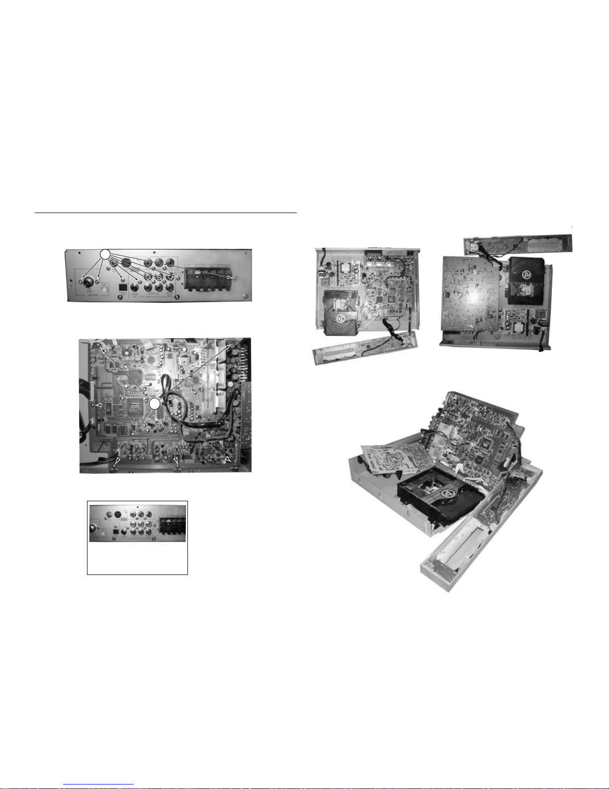
SERVICE POSITIONS
Service position A
Service position B
Note: In some service positions the components or copper patterns of one board may risk touching its neighbouring pc
boards or metallic parts. To prevent such short-circuit use a piece of hard paper or other insulating material between them.
3-2
Dismantling of the Main Board
1) Loosen 8 screws "D" at the back panel as shown in figure 7.
2) Loosen 6 screws "E" on the top of main board as shown in figure 8.
Figure 9
Figure 7
Figure 8
Service position C
RGB Jack use for MRD210/37
MRD210/07
D
E
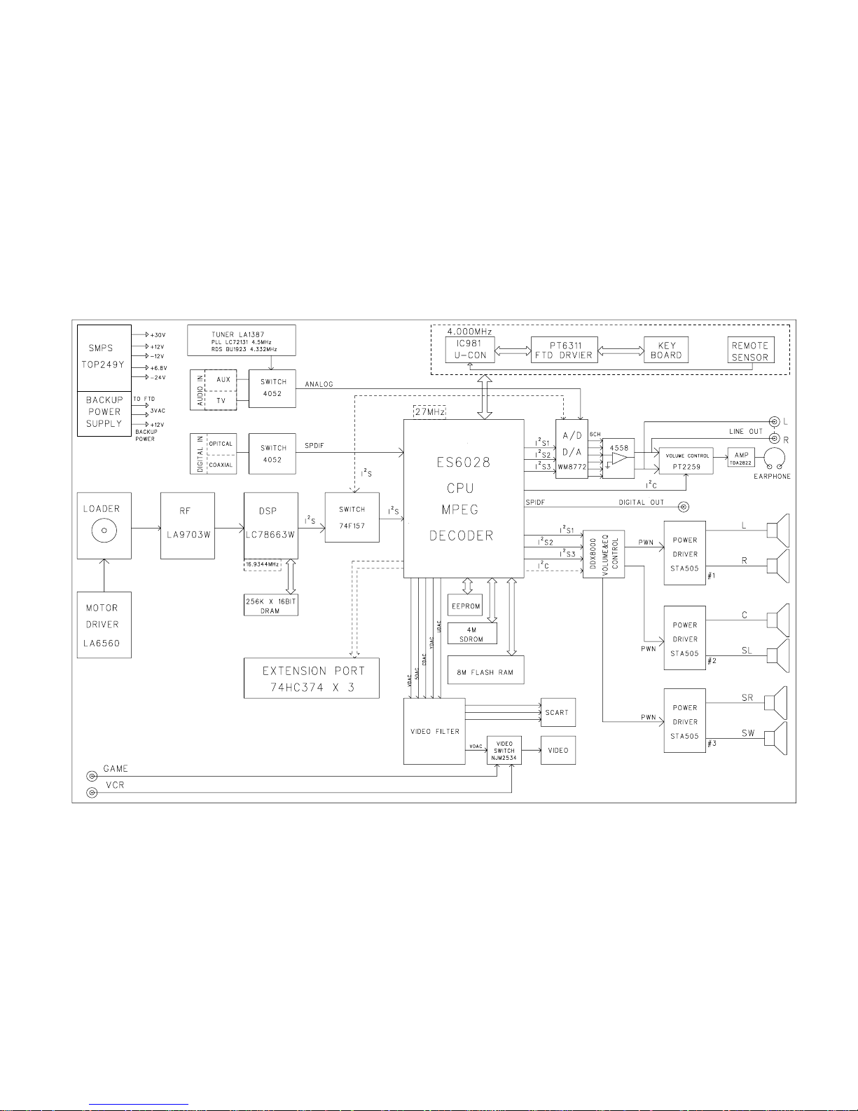
4-1
BLOCK DIAGRAM
4-1
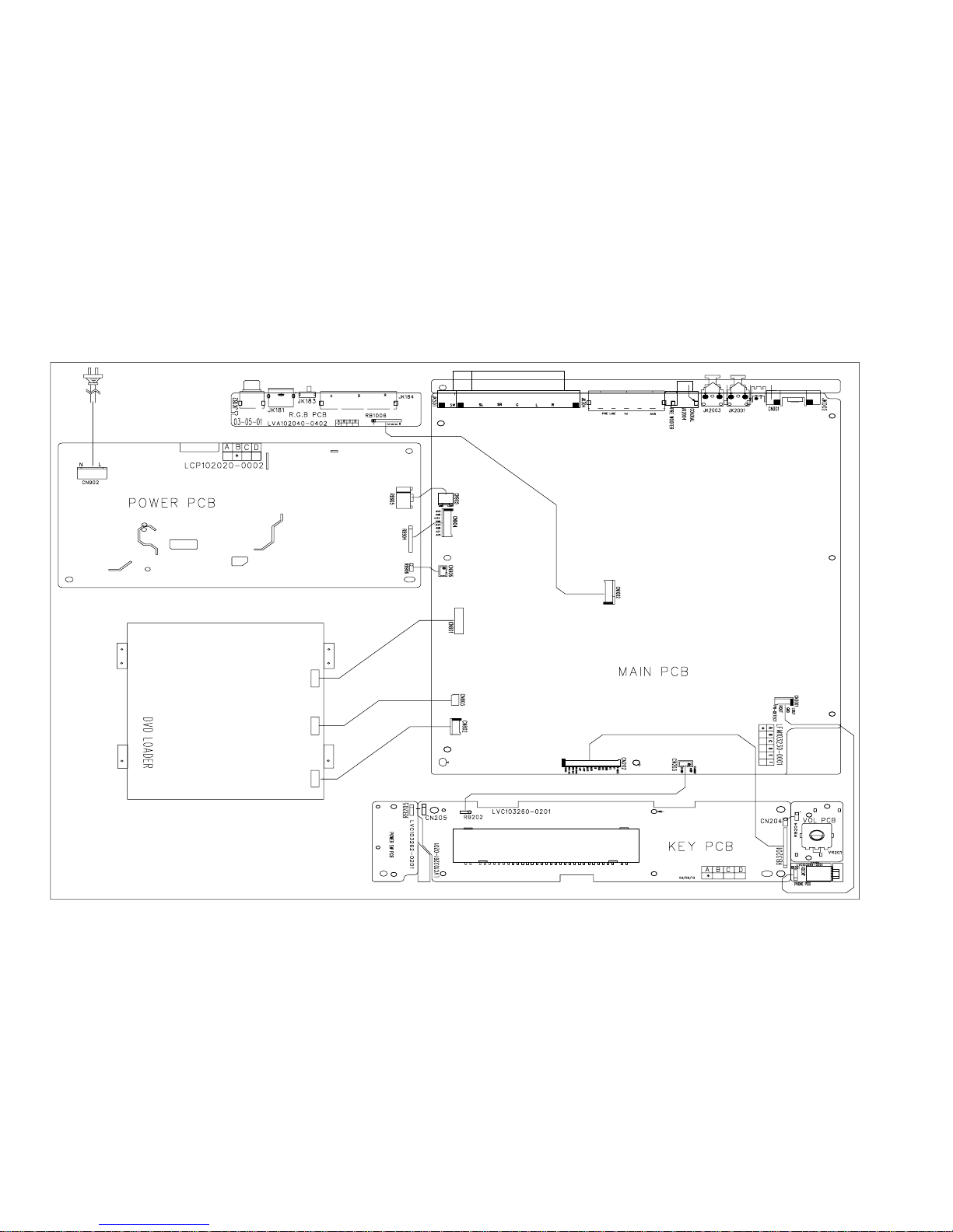
4-2
WIRING DIAGRAM
4-2
 Loading...