

Philips MML1941-PCR, MML1942-PER User Manual
MML194x 1
User’s Manual
LCD 19” MONOCHROME MONITOR
MML1941-PCR
MML1942-PER
Rev. 1.0

MML194x 2
INTENTIONALLY LEFT BLANK

MML194x 3
TABLE OF CONTENTS
INTRODUCTION ................................................................4
CAUTION ..........................................................................5
PRECAUTIONS ..................................................................6
INSTALLATION ...................................................................... 6
HANDLING .......................................................................... 6
MAINTENANCE..................................................................... 6
TRANSPORTATION................................................................. 6
BACKLIGHT .......................................................................... 6
SERVICEABILITY .................................................................... 7
BIOLOGICAL HAZARD AND RETURNS ......................................... 7
DISPOSAL OF THE LCD MONITOR ............................................. 8
PRODUCT DISPOSAL INFORMATION........................................... 9
POWER MANAGEMENT .......................................................... 9
TECHNICAL INFORMATION ............................................. 10
DIMENSIONS .................................................................. 11
MML1942-PER ............................................................... 11
MML1941-PCR ............................................................... 12
INSTALLATION ................................................................ 13
MOUNTING INSTRUCTION .............................................. 14
CONNECTING INSTRUCTION ........................................... 15
INPUT INSTRUCTION ...................................................... 19
CONTROL PANEL DESCRIPTION....................................... 20
BRIGHTNESS KEY FUNCTIONS ......................................... 21
OSD - ON SCREEN DISPLAY ............................................. 23
OSD KEY FUNCTIONS ...................................................... 24
MAIN MENU ...................................................................... 25
INFORMATION ................................................................... 26
LANGUAGE ........................................................................ 26
VIDEO SOURCE ................................................................... 26
KEY LOCK .......................................................................... 27
OSD TIME-OUT ................................................................. 27
OSD HOR. POS. ................................................................. 27
OSD VERT. POS. ................................................................ 28
IMAGE ADJUST ................................................................... 29
HOR. POSITION .................................................................. 30
VERT. POSITION ................................................................. 30
IMAGE SIZE........................................................................ 30
LUT ................................................................................. 31
BLACK VALUE ..................................................................... 31
COLOR EMULATION............................................................. 31
BORDER COLOR .................................................................. 32
FREEZE ............................................................................. 32
ADVANCED ........................................................................ 33
PHASE ADJUST ................................................................... 34
CLOCK ADJUST ................................................................... 34
AUTO CLOCK ..................................................................... 34
AUTO PHASE ..................................................................... 35
VIDEO CALIBRATION ............................................................ 35
RESTORE FACTORY .............................................................. 35
AIC (AMBIENT LIGHT COMPENSATION 000 – 300 LUX) ............ 36
BAUD RATE ....................................................................... 36
5 VOLT - DVI ..................................................................... 36
SERVICE ............................................................................ 37
OFFSET RED....................................................................... 38
OFFSET GREEN ................................................................... 38
OFFSET BLUE ..................................................................... 38
GAIN RED ......................................................................... 39
GAIN GREEN ...................................................................... 39
GAIN BLUE ........................................................................ 39
DAISY ADDRESS .................................................................. 40
ANALOG FILTER .................................................................. 40
ACTUAL BRIGHTNESS ........................................................... 40
EXIT ................................................................................. 41
WARNING MESSAGES .................................................... 42
VIDEO MODES ............................................................... 43
IDENTIFICATION LABEL .................................................. 44
SYMBOLS ....................................................................... 45
GENERAL DEFINITIONS .................................................. 46

4 MML194x
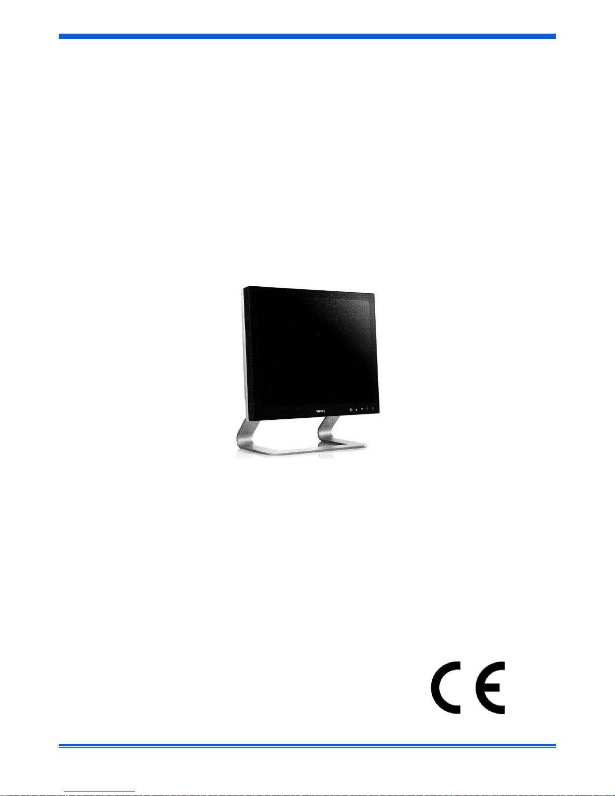
INTRODUCTION
The PHILIPS Medical Grade MML194x is a monochrome active matrix, liquid crystal display exclusively designed for medical
imaging applications.
The monitor can be used for X-ray and PACS and other medical systems requiring a very high level of image quality for
examination and control purpose and can accept an analogue signal input as well as a digital input.
The typical application is for displaying high resolution X-ray images.
This product has much higher brightness than ordinary Flat Panel monitors, equal at least to the brightness level of current highend monochrome CRT monitors used for the same applications.
Other key features of the MML194x family are:
• long term luminance stability through backlight stabilization circuit
• luminance stability vs. the viewing angle
• contrast stability vs. the viewing angle
• brightness uniformity
• automatic brightness control with backlight sensor
• internal automatic greyscale correction (10 bit L.U.T.)
The following models are available:
• MML1941-PCR (equipped with pedestal)
• MML1942-PER (equipped with protective screen)
These monitors, certified/registered by the safety agencies/regulatory authorities as model number 19LCD-XR, follow the
provisions of Medical Directive:
93/42/EEC, Amended by 2007/47/EC (Medical device Class I)
The monitors have been designed to meet the following medical safety requirements, including;
EN 60601-1:1990 + A1:1993 + A2:1995 (2nd Ed.)
EN 60601-1:2006 (3rd Ed.)
IEC 60601-1:1988 + A1:1991 + A2:1995 (2nd Ed.)
IEC 60601-1:2005 + Corr.1: 2006 + Corr.2: 2007 (3rd Ed.)
UL60601-1 1st Ed, 2006-04-26
ANSI/AAMI ES 60601-1: 2005
CAN/CSA-C22.2 No. 601.1-M90, 2005
CAN/CSA-C22.2 No. 60601-1: 2008
• The monitor is intended for indoor use
• Class I Equipment, according to the type of protection against electric shock (*)
• Detachable supply connection
• Continuous Operation, according to the mode of operation,
• Pollution degree classification 2
• Degree of protection against ingress of water: IP20 / IP21
(IP21 with protective screen: monitor tested with a tilt of +5° towards the operator / -15° towards the back side)
• Stationary, in case of “slave” monitor placed in Control Room, not fixed on wall; Fixed, when mounted in MCS.
• Do not use in areas with flammable anesthetics
• Do not use in oxygen rich environments
• The monitor is not intended to be sterilized
• The monitor has been designed to be used in landscape position with a tilt of -15° (backward) and +5° (forward)
(*) To avoid the risk of electric shock, this equipment must only be connected to a supply mains with protective earth
(**) This equipment does not have a gas-sealed electronics enclosure and could ignite any flammable or explosive gases present
in its environment.
MML194x 5
Copyright ©
This manual is covered by Copyright with all rights reserved. Under the copy rights law, this manual may not be copied, in whole
or part, without written consent of Philips. Under the law, copying includes translating into another language or format.
FCC Notice
This equipment has been tested and found to comply with the limits for a class B digital device, pursuant to Part 15 of FCC Rules.
These limits are designed to provide reasonable protection against harmful interference in a residential installation.
This equipment generates, uses and can radiate radio frequency energy and, if not installed and used in accordance with the
instructions, may cause harmful interference to radio communications.
However, there is no guarantee that interference will not occur in a particular installation.
If this equipment does cause harmful interference to radio or television reception, while can be determined by turning the
equipment off and on, the User is encouraged to try to correct the interference by one or more of the following measures:
- Re orient or relocate the receiving antenna.
- Increase the separation between the equipment and receiver.
- Connect the equipment into an outlet on a circuit different from that to which the receiver is connected.
- Consult the dealer or an experienced radio TV technician for help.
Modification
The FCC requires the User to be notified that any changes or modifications made to this device that are not expressly approved by
the manufacturer may void the User’s authority to operate the equipment.
Cables
Connections to this device must be made with shielded signals cables with metallic RFI / EMI connector hoods to maintain
compliance with FCC Rules and Regulations.
The lighting flash with arrowhead symbol is intended to alert the User about the presence of not insulated “dangerous
voltages” within the product’s enclosure that may be sufficient magnitude to constitute a risk of electrical shock to
people.
The exclamation mark is intended to alert the User about the presence of important operating and maintenance
(servicing) instructions in literature accompanying the appliance.
CAUTION
RISK OF ELECTRICAL SHOCK
DO NOT OPEN
ATTENTION
RISQUE DE CHOC ELECTRIQUE
NE PAS OUVRIR
CAUTION: TO REDUCE THE RISK OF ELECTRICAL SHOCK.
DO NOT REMOVE COVER (OR BACK)
NO USER SERVICEABLE PARTS INSIDE
REFER SERVICING TO QUALIFIED SERVICE PERSONNEL
WARNING:
TO PREVENT DAMAGE WHICH MAY RESULT IN FIRE OR SHOCK HAZARD,
DO NOT EXPOSE THIS APPLIANCE TO RAIN OR EXCESSIVE MOISTURE.
THE ENCLOSURE HAS TO BE CHECKED UPON COLLISION DAMAGE; REFER
TO QUALIFIED SERVICE PERSONNEL

6 MML194x
PRECAUTIONS
Installation
Power cord: due to the different power cable lengths necessary at system level, the power cable is not provided with this LCD
monitor.
in Europe, use a power cord H05VV-F or H05VVH2-F rated 0.75mm
2
250V, with a Plug rated 10A 250V. At least one
European safety mark is required.
in US and Canada, use a power cord with plug “hospital grade”, provided with instructions to indicate that grounding
reliability can be achieved only when the equipment is connected to an equivalent receptacle marked hospital only or
hospital grade. Rating, min 18 AWG SJT 60°C 300V, Plug NEMA 5-15 P, Connector IEC 320. The cURus safety mark is
required.
Contact the local dealer if you have doubt on the right cord set to be used.
Protective earth: to avoid the risk of electric shock, this equipment must only be connected to a supply mains with protective
earth. (Class I Equipment)
Cables: when the monitor is assembled in the medical system, take care of the anchorage of all cables, to avoid unwanted
detachment
Connections: any external connection with other peripherals must follow the requirements of clause 16 of IEC60601-1 3rd ed. or
Table BBB.201 of IEC 60601-1-1 for the medical electrical systems.
The equipment should be installed near an easily accessible outlet.
Do not install or leave the monitor:
In places subject to extreme temperatures, for example near a radiator, heating vent, or in direct sunlight. Subjecting the
LCD monitor to extreme temperatures, could cause deformations of the casing or malfunctions.
Provide adequate ventilation to the monitor, do not block the ventilation holes.
In places subject to mechanical vibration or shock.
Near any equipment that generates a strong magnetic field.
In places subject to inordinate amounts of dust, dirt, or sand, for example near an open window or an outdoor exit.
If setting up temporarily in an outdoor environment, be sure to take adequate precautions against airborne dust and dirt otherwise
irreparable malfunctions could occur.
Handling
Do not press on or scratch the LCD screen. Do not place a heavy object on the LCD screen. This may cause the screen to lose
uniformity or cause LCD panel malfunctions.
If the monitor is used in a cold place, a residual image may appear in the screen. This is not a malfunction.
The screen returns to normal as temperature rises to normal operating level.
If a still picture is displayed for a long time, a residual image may appear for a while. The residual image will eventually
disappear.
The LCD panel becomes warm during normal operation. This is not a malfunction.
Maintenance
Be sure to unplug the power chord from the mains when cleaning your LCD monitor.
The front polarizer can be easily damaged. Take care not to scratch the front surface with any hard or abrasive material. Dust,
finger marks, grease etc. can be removed with a soft damp cloth (a small amount of mild detergent can be used on the damp
cloth). Do not apply water or detergent directly to the front surface as this may cause staining or damage the electronic
components. Never use any solvent on the front polarizer or module as this may cause permanent damage. Wipe off water drop
immediately. Long contact with water may cause discoloration spots. When the panel surface is soiled, wipe it with absorbent
cotton or other soft cloth.
Transportation
Disconnect all cables from the monitor when transporting.
When you transport this LCD display, hold the base sections of the display stand firmly in both hands. If you drop the monitor,
you may be injured or the monitor may be damaged.
When you transport this monitor for repair or shipment, use the original cardboard box and packing materials.
Be always sure that the monitor is stable and safe during the transport: the pedestal is not suitable for using the monitor in
movable system; in these cases use the VESA mounting holes.
Backlight
Specially designed fluorescent tubes are installed as back-lighting apparatus for this monitor. If the screen turns dark, unstable, or
does not come on, consult your Customer service for replacing the monitor.

MML194x 7
Serviceability
There are no User serviceable parts within the 19” LCD monitor. Attempting to open or disassemble the monitor may expose the
User to hazardous voltages, risk of excessive temperatures, fire or explosion from enclosed energy sources, or impairment of
function. This product is intended to be installed in a medical system only by trained system integrator.
Biological Hazard and Returns
The structure and the specifications of this device as well as the materials used for manufacturing make it easy to wipe and clean
and therefore suitable to be used for various applications in hospitals and other medical environments, where procedures for
frequent cleaning are specified. However, normal use shall exclude biological contaminated environments, to prevent spreading of
infections. Therefore use of this device in such environments is at the exclusive risk of Customer. In case this device is used where
potential biological contamination cannot be excluded, Customer shall implement the decontamination process as defined in the
latest edition of the ANSI/AAMI ST35 standard on each single failed Product that is returned for servicing, repair, reworking or
failure investigation to Seller (or to the Authorized Service Provider). At least one adhesive yellow label shall be attached on the
top site of the package of returned Product and accompanied by a declaration statement proving that the Product has been
successfully decontaminated. Returned Products that are not provided with such external decontamination label, and/or whenever
such declaration is missing, can be rejected by Seller (or by the Authorized Service Provider) and shipped back at Customer
expenses.

8 MML194x
For the design of MML194x LCD monitors, special attention has been placed to the environmental impact of the product:
packaging, product’s weight and energy consumption have been optimized vs. its performances. Then, please consider the
following notes in the disposal of the product.
The monitor’s packaging is re-usable, please retain the packaging for future use.
Disposal of the LCD monitor
Do not dispose of this monitor with general household waste.
The fluorescent tubes used in this LCD monitor contain mercury. Disposal of this monitor must be carried out in accordance with
the regulations of your local sanitation authority.
WARNING
The fluorescent lamps in the liquid crystal
display (LCD) contain mercury.
Do not put it in trash that is disposed of in
landfills.
Dispose of it as required by local ordinances
or regulations.
MML194x 9
Product disposal information
Directive 2002/96/EC on waste of electrical and electronic equipment (WEEE).
For countries in the European Union
This symbol indicates that this product (including the cables, plugs and accessories) must not be disposed of with
the other household waste. Instead, it is your responsibility to dispose of your waste equipment by handing it over to
a designated collection point for the recycling of waste electrical and electronic equipment. The separate collection
and recycling of your waste equipment at the time of disposal will help preserve natural resources and ensure that
your waste equipment is recycled in a manner that protects human health and environment. For more information
about where you can drop off your waste equipment for recycling, please contact your local city office, or your
supplier’s office.
For countries outside the European Union
Disposal of electrical products in countries outside the European Union should be done in line with local
regulations.
Directive 2002/95/EC on the restriction of certain hazardous substances in electrical and electronic equipment (RoHS)
According to what declared by our components supplier, this product is RoHS compliant.
Directive 1907/2006/EC on Registration, Evaluation, Authorization and Registration of Chemicals (REACH)
Information on REACH Substances of Very High Concern (SVHCs) in our products can be found on the PHILIPS website
www.philips.com/about/sustainability/reach. The information will be regularly updated.
Power management
If the power management function of the computer connected to the MML194x display is enabled, the monitor turns to and from
Stand-by automatically.
The User can control power management features from the computer.
MODE LED POWER CONSUMPTION (typical)
Power ON Green 55W (*)
Stand-by Orange 8.3W
Switch OFF Not illuminated 0W
(*) Factory settings

10 MML194x
TECHNICAL INFORMATION
Display Panel 19” (482 mm) SXGA active matrix monochrome TFT/LCD
Resolution Horizontal 1280 dots
Vertical 1024 lines
Supported Grayscale 8-bit
Dimensions 425 x 375 x 96,8 mm (width x height x depth.)
Weight 5560g (MML1942-PER), 7580g (MML1941-PCR), 2380g ( pedestal )
Active display area 376.32 x 301.056 mm ( width x height )
Response Time 40 ms ( 10% to 90% rising + 90% to 10% falling )
Viewing Angle ± 85° typ. horizontal or vertical ( contrast ratio ≥ 20 )
Contrast Ratio 800 : 1 typ.
White luminance 500 cd/m2
Pixel Pitch 0.294 (one triad) x 0.294 mm ( width x height )
Video interface
Analog Input: • BNC connection for Composite Video Signal
• DSUB-15 connection for Separate Sync Video Signal or SOG Video Signal.
• Analog on DVI (DVI-I connector)
Digital Input: • DVI-D connection for TMDS signal link standard version.
Analog Output: • BNC connection for Loop Through Composite Video Signal.
Scanning Frequency Max pixel clock 165 MHz
Power Consumption <58 W max
Power Supply From 90 to 264 Vac , 45 - 66 Hz
Operation Temperature +10 to +40° C
Storage Temperature -20 to +60° C
Humidity 80% ( Maximum Wet-Bulb should be 39° C and No condensation )
Altitude: Operative ≤ 3000m (70kPa)
Storage ≤ 3000m (70kPa)
MML194x 11
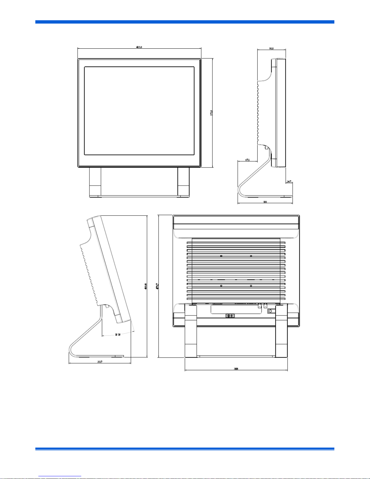
DIMENSIONS
MML1942-PER
12 MML194x
MML1941-PCR

MML194x 13
INSTALLATION
Before unpacking the monitor, prepare a suitable workspace: a stable and level surface near a grounded wall outlet in
an area that is relatively free of glare from sunlight or other sources of bright light. Do not block the cooling vents.
NOTE: before installing this monitor, please refer to the User’s Guide of the attached computer and/or video adapter
to check if these devices require any change of setting.
Positioning
WARNING:
WHEN POSITIONING THIS EQUIPMENT, ENSURE THAT THE MAINS PLUG AND SOCKET ARE EASILY
ACCESSIBLE
While unpacking the monitor, inspect all package contents for any eventual shipping damage that could cause a fire or
shock hazard.
Immediately report any shipping damage to the carrier or transportation company and contact customer service for
assistance. Keep all packaging material in case you need to ship, store or return the monitor.
After unpacking the monitor, make sure the following items are included:
MML1942-PER
• Monitor
• This User’s Manual
• Warning Note DMR147472
• User Manual MML194x Series CCC version 4519 206 1101.x
• 4 VESA Screws M4x25mm 4519 200 40451
• 4 VESA Screws M4x25mm 4519 200 40181
• 4 VESA Screws M4x30mm 4519 200 40441 (mounted in VESA holes)
• 4 Lock washer 4519 200 40191 (mounted in VESA holes)
• 4 Plain washer 4519 200 40201 (mounted in VESA holes)
MML1941-PCR
• Monitor
• This User’s manual
• RS232 to RJ11 (RJ10) 4p4c (4 pins, 4 connectors) interface cable
• Warning Note DMR147472

14 MML194x
MOUNTING INSTRUCTION
Pedestal (MML1941-PCR)
With the built-in pedestal the monitor can be tilted for a most comfortable viewing angle as shown in figure here
below.
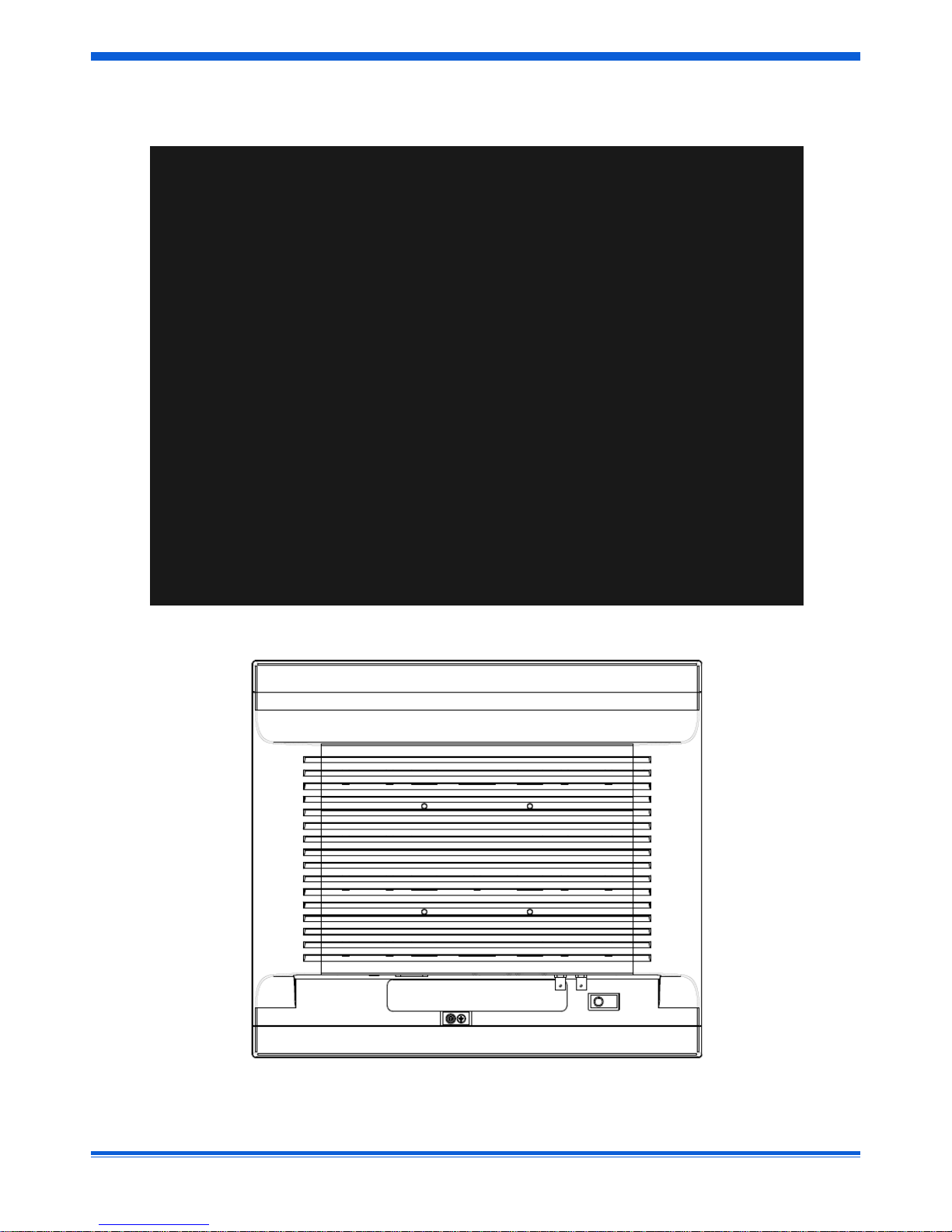
VESA Plate (MML1942-PER)
The arm with VESA (100mm x 100mm) interface must be fixed to the monitor with the 4 screws already present on
the back cover.
Note: If not available, use M4 x 25 screws, spring washers and plain washers (see figure above).

MML194x 15
CONNECTING INSTRUCTION
Additional Protective Earth Pin
The position of the external ground safety connector (to fix by screw with lock washer M4x12 max) is indicated in the
figure below.
Protective earth pin
 Loading...