

Page 1
3122 785 16320
Page 2
BDLx221/00
2
Important Safety Notice
x2PM8822/xx
Proper service and repair isimportant to the safe, reliable
operation of all HPConsumer Electronics Company**
Equipment. The service procedures recommended by HP and
described in this service manual are effective methods of
performing service operations. Some ofthese service
operations require the use of tools specially designed for the
purpose. The special tools should be used when and as
recommended.
It is important to note that this manual contains various
CAUTIONS and NOTICES which should be carefully read in
order to minimize the risk of personal injury to service
personnel. The possibility exists that improper service
methods may damage the equipment. It is also important to
understand that these CAUTIONS and NOTICES ARE NOT
EXHAUSTIVE. HP could not possibly know, evaluate and
advise the service trade of all conceivable ways in which
service might be done or of the possible hazardous
consequences of each way. Consequently, HP has not
undertaken any such broad evaluation. Accordingly, a
servicer who uses a service procedure or tool which is not
recommended by HP must first satisfy himself thoroughly that
neither his safety nor the safe operation of the equipment will
be jeopardized by the service method selected.
* * Hereafter throughout this manual, HP Consumer
Electronics Company will bereferred to as HP.
WARNING
Critical components having special safety characteristics are
identified with a bythe Ref. No. inthe parts list and
enclosed within a broken line*
(where several critical components are grouped in one area)
along with the safety symbol on the schematics or
exploded views.
Use of substitute replacement parts which do not have the
same specified safety characteristics may create shock, fire,
or other hazards.
Under no circumstances should the original design be
modified or altered without written permission from Philips.
Philips assumes no liability, express or implied, arising out of
any unauthorized modification of design.
Servicer assumes all liability.
FOR PRODUCTS CONTAINING LASER :
DANGER- Invisible laser radiation when open.
AVOID DIRECT EXPOSURE TO BEAM.
CAUTION- Use of controls or adjustments or
performance of procedures other than
those specified herein may result in
hazardous radiation exposure.
CAUTION- The use of optical instruments with this
product will increase eye hazard.
TO ENSURE THE CONTINUED RELIABILITY OF THIS
PRODUCT, USE ONLY ORIGINAL MANUFACTURER'S
REPLACEMENT PARTS, WHICH ARE LISTED WITH THEIR PART
NUMBERS IN THE PARTS LIST SECTION OF THIS
SERVICE MANUAL.
Take care during handling the LCD module with backlight
unit
- Must mount the moduleusing mounting holes arranged infour
corners.
- Do not press onthe panel, edge of theframe strongly or electric
shock as this will result in damage to the screen.
- Do not scratch orpress on the panel withany sharp objects, such
as pencil or pen asthis may result in damage to the panel.
- Protect the module fromthe ESD as it maydamage the electronic
circuit (C-MOS).
- Make certain that treatment person s body are grounded through
wrist band.
- Do not leave themodule in high temperature andin areas of high
humidity for a long time.
- Avoid contact with water as it may ashort circuit within the module.
- If the surface ofpanel become dirty, please wipe it off with a soft
material. (Cleaning with a dirty or rough cloth may damage the
panel.)
Page 3
Technical Data
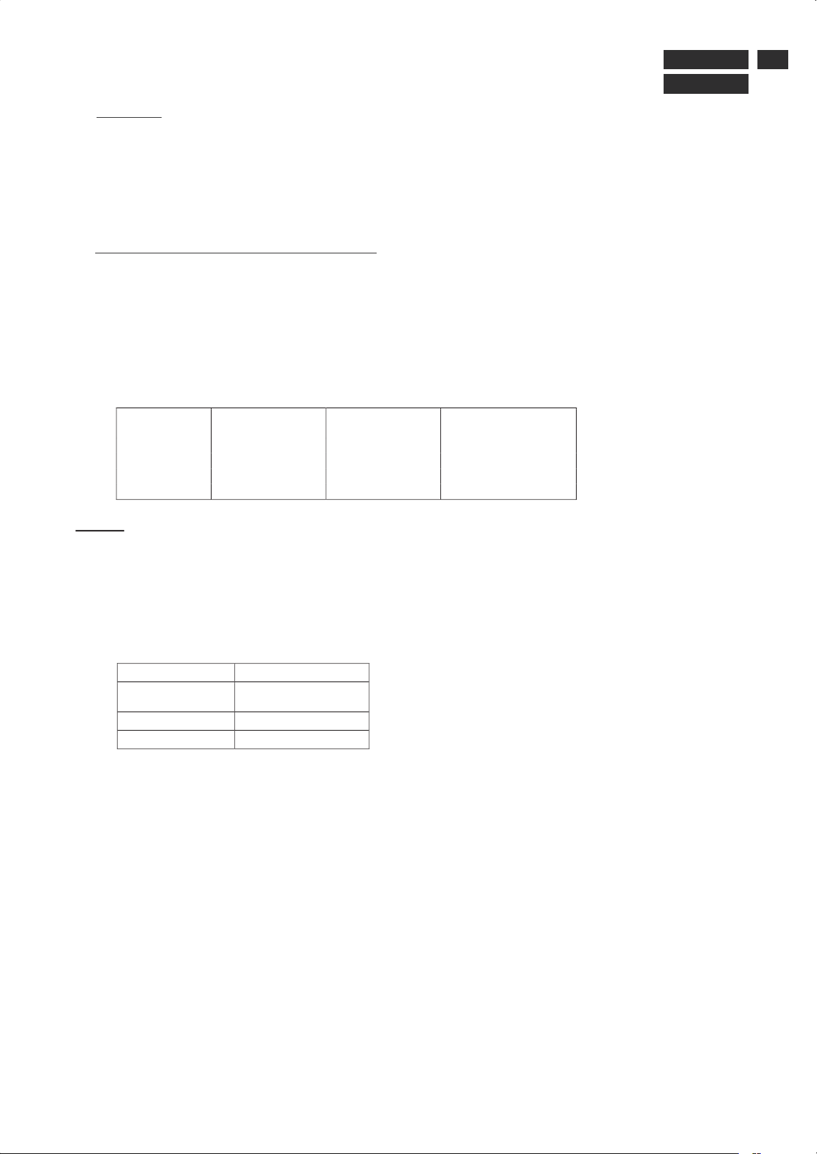
2. Technical Specifications of Mirror TV
This section will provide information on the physical dimensions of the
Mirror TV, allowing customers to use the product in many ways (such as
to create new custom decorative frames, for example).
2.1. Dimensional information
The table below contains the dimensional information of the various
models:
Model no.
W
(mm/ inches)
H
(mm/ inches)
D
(mm/inches)
32” landscape
888.9 / 35.0
575.4 / 22.66
140 / 5.51
32” portrait
575.4 / 22.66
888.9 / 35.0
140 / 5.51
42” landscape
1116.9 / 43.97
688.8 / 27.12
159.9 / 6.30
42” portrait
688.8 / 27.12
1116.9 / 43.97
159.9 / 6.30
Legend:
W
: Width
H
: Height
D
: Depth
2.2. Weight information
The following table contains the weight information of the Mirror TV:
Mirror TV Model no.
Weight
(kg)
(Mirror TV with
decorative frame)
32”
24.5
42”
40
BDLx221/00
x2PM8822/xx
1. General
1.1.Product description
This 32" or 42" Mirror TV is specified as a display peripheral with PC analog video signal input and
includes TV/DTV function with 32" or 42" TFT LCD display.
For all Mirror TV's technical data and functionnalities see Service Manual 32" WXGA TFT LCD Monitor/TV
(3138 106 1048x) or BDS 42" LCD Monitor/TV (3138 106 1049x).
3
Page 4
Decorative Frame
BDLx221/00
4
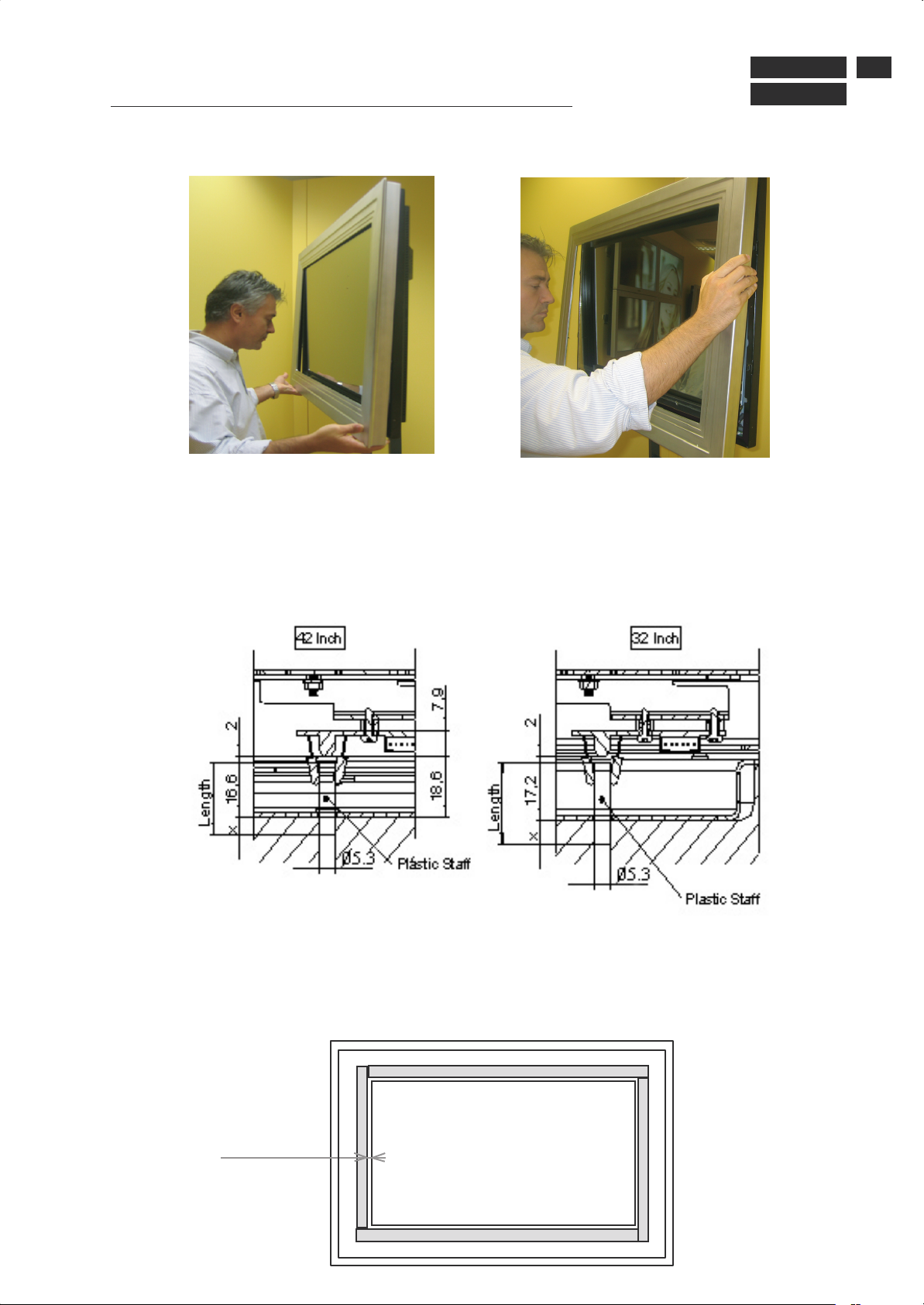
Changing the decorative Frame or mounting frame
3
3.1
Disassembly
Pull forward one side of decorative frame with light force. The clicking devices will unlatch.
Remove the complete mounting frame including decorative frame.
1st 2nd
Unscrew the decorative frame mounting frame. Lift of decorative frame from mounting frame,
beware of plastic tube for IR. Screw metal mounting frame on decorative frame.
For a new decorative frame add the 4 foam strips (see mounting in chapter 3.3) and PHILIPS
adhesive logo.
For a new mounting frame add the 8 new strikers (see mounting in chapter 4.1).
x2PM8822/xx
3.2
changing light pipe
Remove the damaged tube by pushing it out.
The new plastic tube make sure the tube sticks out 16.6 (17.2) mm inside the metal mounting frame.
3.3 changing foam.
Unscrew the decorative frame of mounting frame. Lift of decorative frame from mounting frame,
beware of plastic tube for IR. Screw metal mounting frame on decorative frame.
Unstick the damaged foam strip and stick a new foam with 1 to 2 mm from the inner side of
decorative frame. During this installation do not pull the stick for do not extend it.
See following drawing for disposition.
1 to 2 mm
Page 5
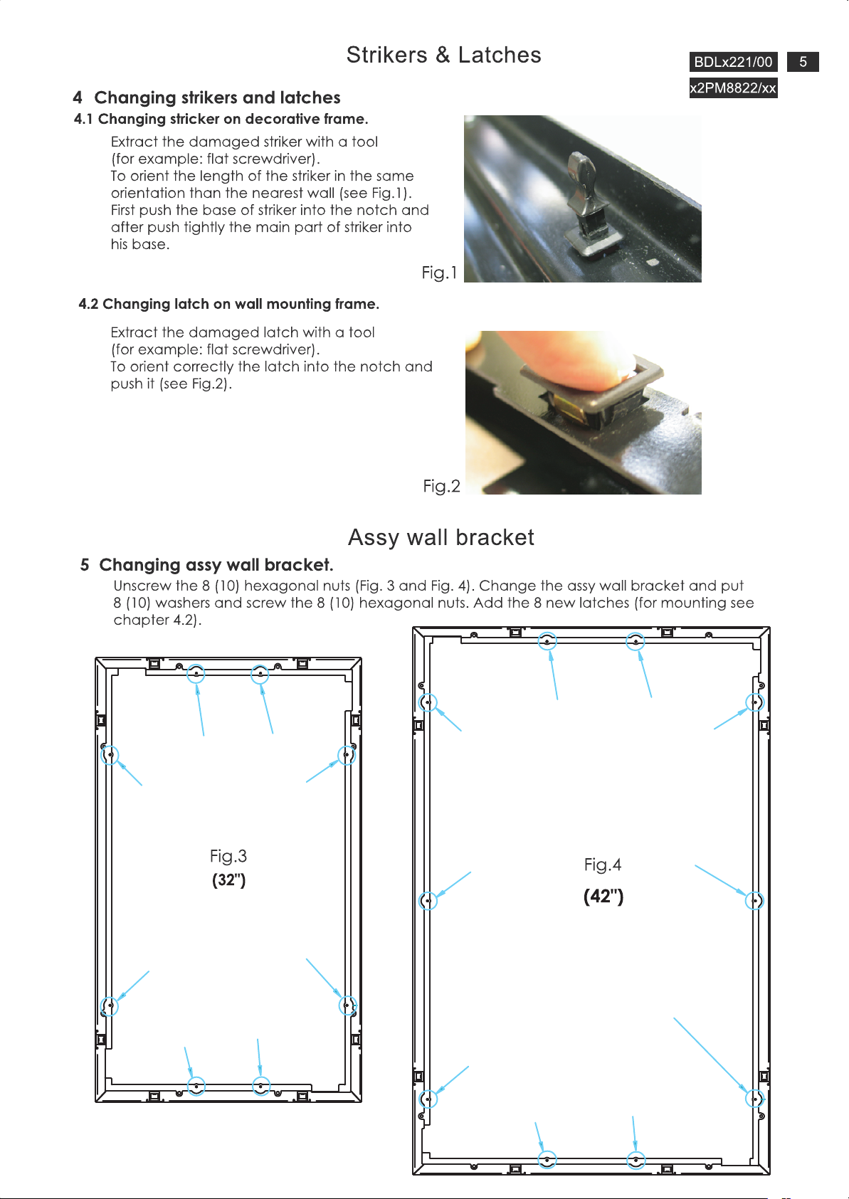
Page 6
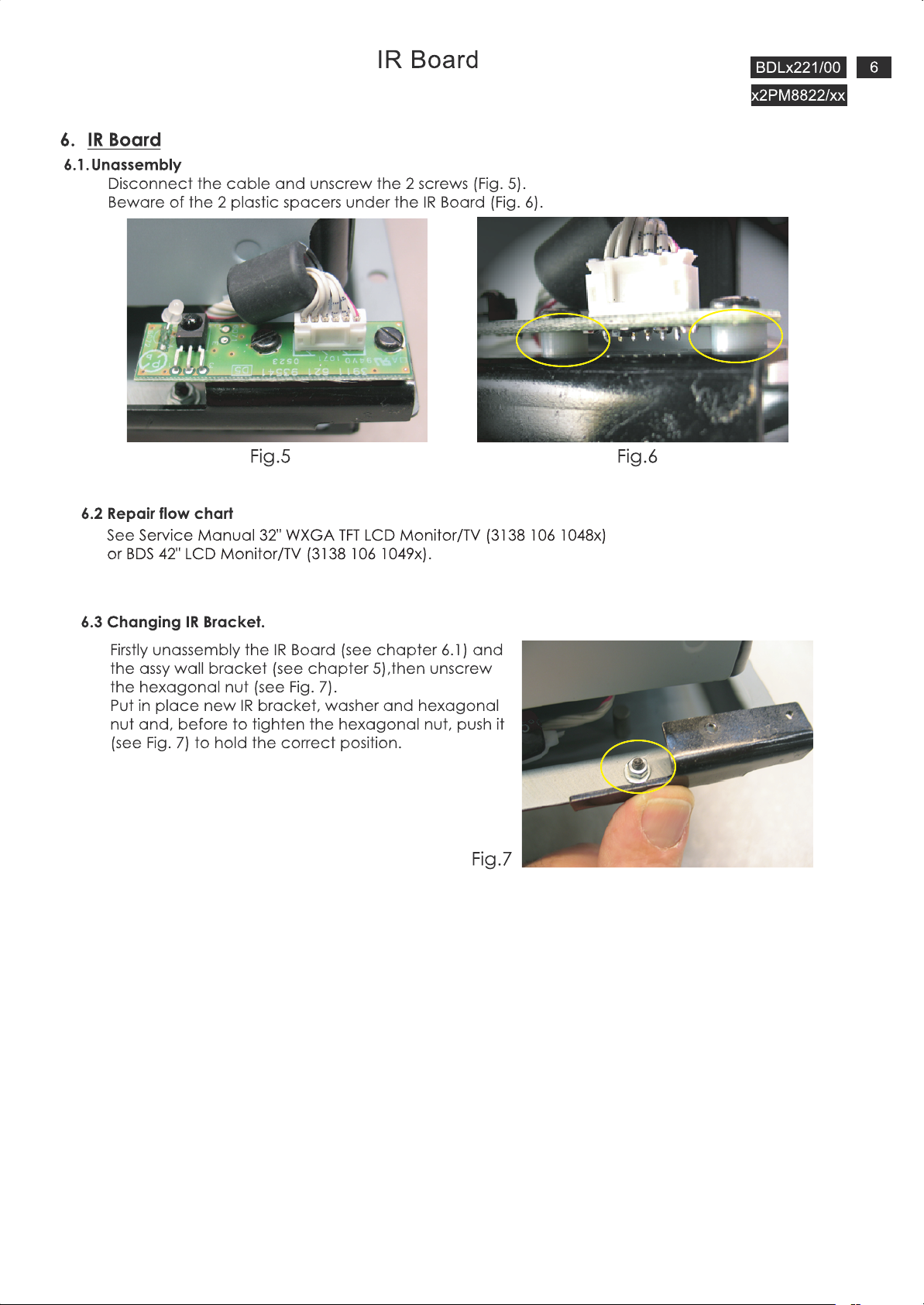
Page 7
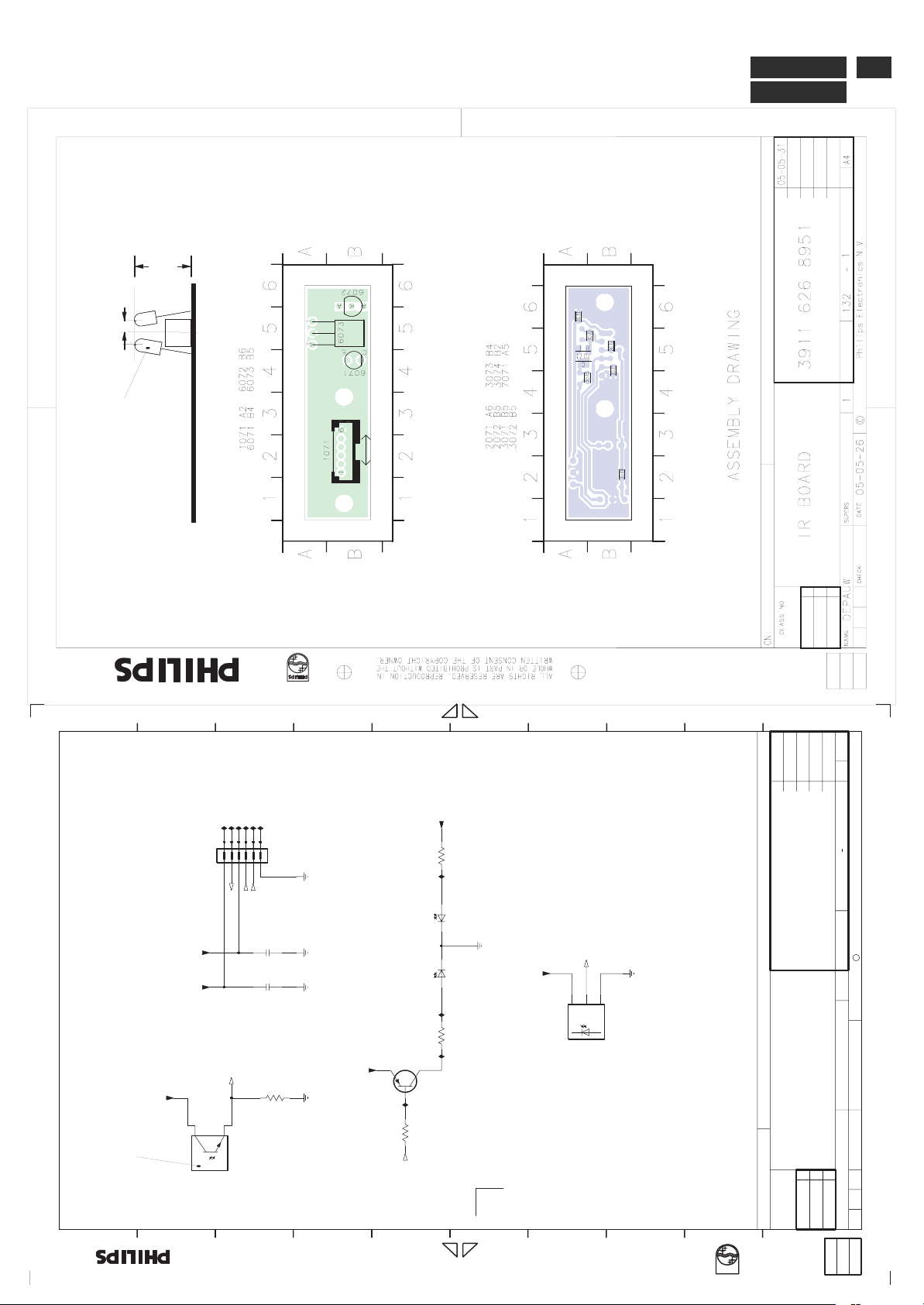
5.4.Technical data
10
5.6
No Connected
IR Board
BDLx221/00
x2PM8822/xx
7
A
B
C
D
E
F
G
6543
F005
F006
F004
F002
F001
F003
1071
123
+5TM
MCU_3V3
21
+5TM
No Connected
6071
63386
456
RC5
LED_GREEN
LIGHT_SENSOR
100n
2072
100n
2071
LIGHT_SENSOR
1K5
3071
L-97DSP7C
MCU_3V3
+5TM
3074
220R
I004I002 I003
BLUE
L-3WSYKPBW
6072-2
6072-1
L-3WSYKPBW
YELLOW
3073
220R
BC857B
7071
I001
4K7
3072
MCU_3V3
RC5
VS
OUT
GND
6073
H
I
J
A4130
05-05-31
1
65
1
3911 626 8951
KONINKLIJKE PHILIPS ELECTRONICS N.V. 2004
4
C
1
TSOP34136
S/A PCB
SETNAMECHN
MIRROR TV IR LED
321
2005-05-26
SUPERS.
DATE
CHECK
LED_GREEN
******
CLASS_NO
A
B
C
D
E
owner.
is prohibited without the written consent of the copyright
All rights reserved. Reproduction in whole or in parts
F
G
H
toestemming van de auteursrechthebbende.
gedeeltelijk, is niet toegestaan dan met schriftelijke
Alle rechten voorbehouden. Verveelvuldiging, geheel of
I
DEPAUW
NAME
J
Page 8

Page 9
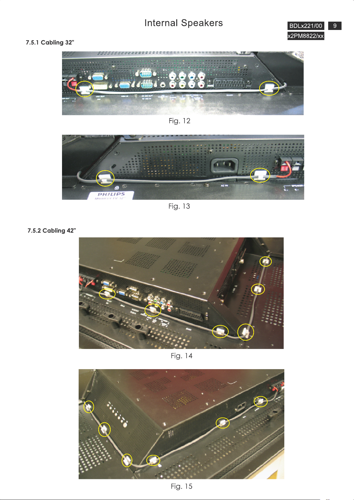
Page 10
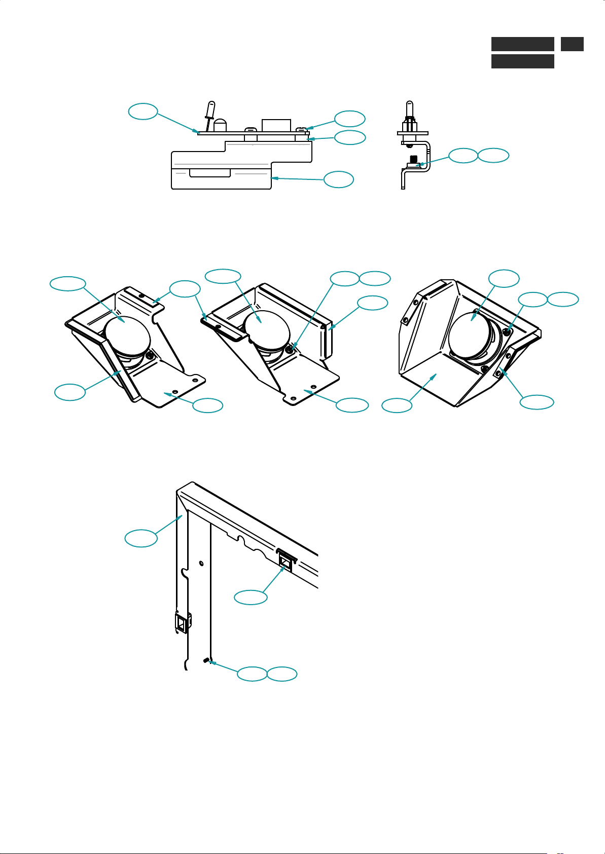
8. Spare Parts List
IR Led
Spare Parts List
BDLx221/00
x2PM8822/xx
10
Internal speakers
32" (Right)
0150
0220
0005
0210
0150
0070
32" (Left)
0110
0040
0050
0160 0170
0230
0080
0070
0130 0140
42"( right & left)
0150
0160 0170
0200
Assy wall bracket
0060
0180
0100
0110
Page 11
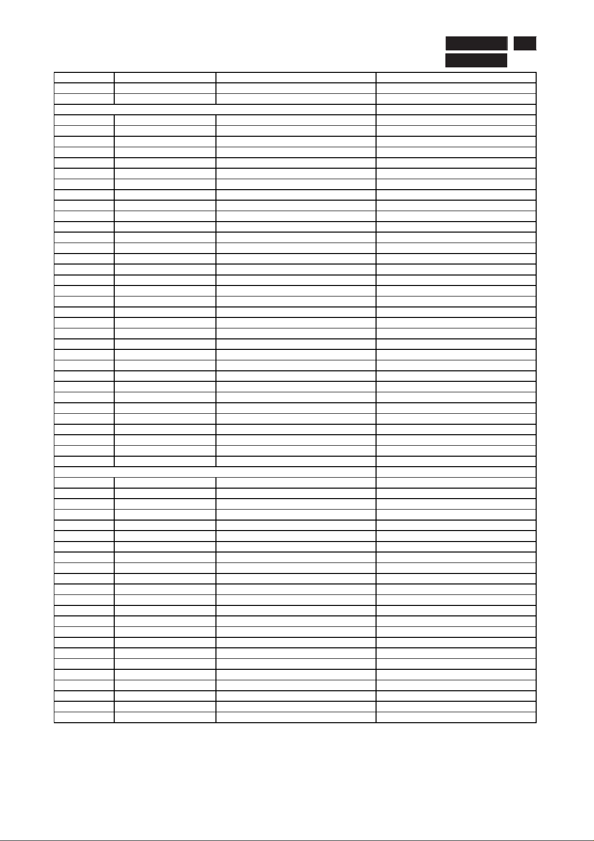
Spare Parts List
BDLx221/00
x2PM8822/xx
BDL3221M/00
32PM8822/10
32PM8822/27
For monitor repair use service manual BDL3221V/00 - 313810610486
30 3911 626 89510 LED S/A MIRROR TV IR LED
40 3911 620 02941 FRAME, PLASTIC "DECORATIVE FRAME 32"
50 2511 300 20049 SCREW, PLASTIC "SCREW 2,9X9,5
60 2511 300 20043 SPACER, PLASTIC SPACER FOR IR RECEIVER
70 9965 000 34157 BRACKET, PLASTIC BRACKET IR LED FROM 32"
80 9965 000 34158 BRACKET, STEEL ASSY WALL BRACKET 32"
90 9965 000 34159 LOUDSPEAKER BOX, WITHOUT L.S. SPEAKER HOUSING 32" RIGHT
0 9965 000 34160 LOUDSPEAKER BOX, WITHOUT L.S. SPEAKER HOUSING 32" LEFT
10
0 9965 000 34161 BRACKET, STEEL WALL BRACKET 32"
11
0 2411 300 20141 LOUDSPEAKER SPEAKER 8 OHM 15 W
12
13
0 2511 300 20041 BRACKET, PLASTIC LATCH PART
0 9965 000 34162 FRAME, STEEL ASSY MOUTING FRAME 32P
14
0 2511 300 20042 PIN, STEEL STRIKER
15
0 3911 621 93781 CUSHION, FOAM PLASTIC FOAM SPEAKER 32
16
17
0 3911 621 93791 CUSHION, FOAM PLASTIC FOAM SPEAKER 32 RIGH
0 3911 621 93801 CUSHION, FOAM PLASTIC FOAM SPEAKER 32 LEFT
18
0 3911 621 93811 CUSHION, FOAM PLASTIC FOAM FOR GLASS 32 SIDE
19
0 3911 621 93821 CUSHION, FOAM PLASTIC FOAM FOR GLASS 32 TOP-BO
20
21
0 9965 000 34163 PLATE, GLASS MIRROR GLASS 32"
0 1211 300 10007 TAPE ADHESIVE, PLASTIC DOUBLE SIDE ADHESIVE TAPE
22
0 3911 626 89961 KIT, SERVICE, TV S/A KIT MUSHROOM
23
0 3104 304 27661 SPACER, RUBBER WALL SPACER BLACK 2K4
24
25
0 3104 308 78841 SCREW, STEEL BAG SCREWS WALLMOUNT FTV2K4
0 8639 000 16589 PR.CIRCUIT, T.V. TUNER MODULE EUROPE
26
0 3911 629 05361 CABLE, CONNECTING SPEAKER CABLE 32 RIGHT
27
0 3911 629 05371 CABLE, CONNECTING SPEAKER CABLE 32 LEFT
28
29
0 2511 300 20052 CLIP, PLASTIC CLIP
0 4822 454 13455 PLATE, NAME WORDMARK PHIL. FL6 29" DL SS
30
0 3911 626 94481 GUIDE, LIGHT, PLASTIC S/A LIGHT PIPE
31
11
BDL4221M/00
42PM8822/10
42PM8822/27
For monitor repair use service manual BDL4221V/00 - 313810610490
30 3911 626 89510 LED S/A MIRROR TV IR LED
40 3911 620 02951 FRAME, PLASTIC "DECORATIVE FRAME 42
50 2511 300 20043 SPACER, PLASTIC SPACER FOR IR RECEIVER
60 9965 000 34164 BRACKET, PLASTIC BRACKET IR LED FROM 42"
70 9965 000 34165 BRACKET, STEEL ASSY WALL BRACKET 42"
80 9965 000 34166 LOUDSPEAKER BOX, WITHOUT LS SPEAKER HOUSING 42"
90 9965 000 34167 BRACKET, STEEL WALL BRACKET 42"
0 2511 300 20041 BRACKET, PLASTIC LATCH PART
10
0 2511 300 20042 PIN, STEEL STRIKER
11
0 9965 000 34168 FRAME, STEEL ASSY MOUTING FRAME 42P
12
0 3911 621 93831 CUSHION, FOAM PLASTIC FOAM SPEAKER 42
13
0 3911 621 93841 CUSHION, FOAM PLASTIC FOAM FOR GLASS 42 SIDE
14
0 3911 621 93851 CUSHION, FOAM PLASTIC FOAM FOR GLASS 42 TOP-BO
15
0 9965 000 34169 PLATE, GLASS "MIRROR GLASS 42"
16
0 1211 300 10007 TAPE ADHESIVE, PLASTIC DOUBLE SIDE ADHESIVE TAPE
17
0 3911 626 89961 KIT, SERVICE, TV S/A KIT MUSHROOM
18
0 3104 304 27661 SPACER, RUBBER WALL SPACER BLACK 2K4
19
0 3104 308 78841 SCREW, STEEL BAG SCREWS WALLMOUNT FTV2K4
20
0 8639 000 16589 PR.CIRCUIT, T.V. TUNER MODULE EUROPE
21
0 2511 300 20052 CLIP, PLASTIC CLIP
22
0 4822 454 13455 PLATE, NAME WORDMARK PHIL. FL6 29" DL SS
23
0 3911 626 94481 GUIDE, LIGHT, PLASTIC S/A LIGHT PIPE
24
0 3911 629 05381 CABLE, CONNECTING SPEAKER CABLE 42
25
Page 12
12
BDLx221/00
x2PM8822/xx
Repair Tips
0. Warning
All ICs and many other semi-conductors are susceptible to
electrostatic discharges (ESD). Careless handling during
repair can reduce life drastically. When repairing, make sure
that you are connected with the same potential as the mass
of the unit via a wrist wrap with resistance. Keep components
and tools also at the same potential !
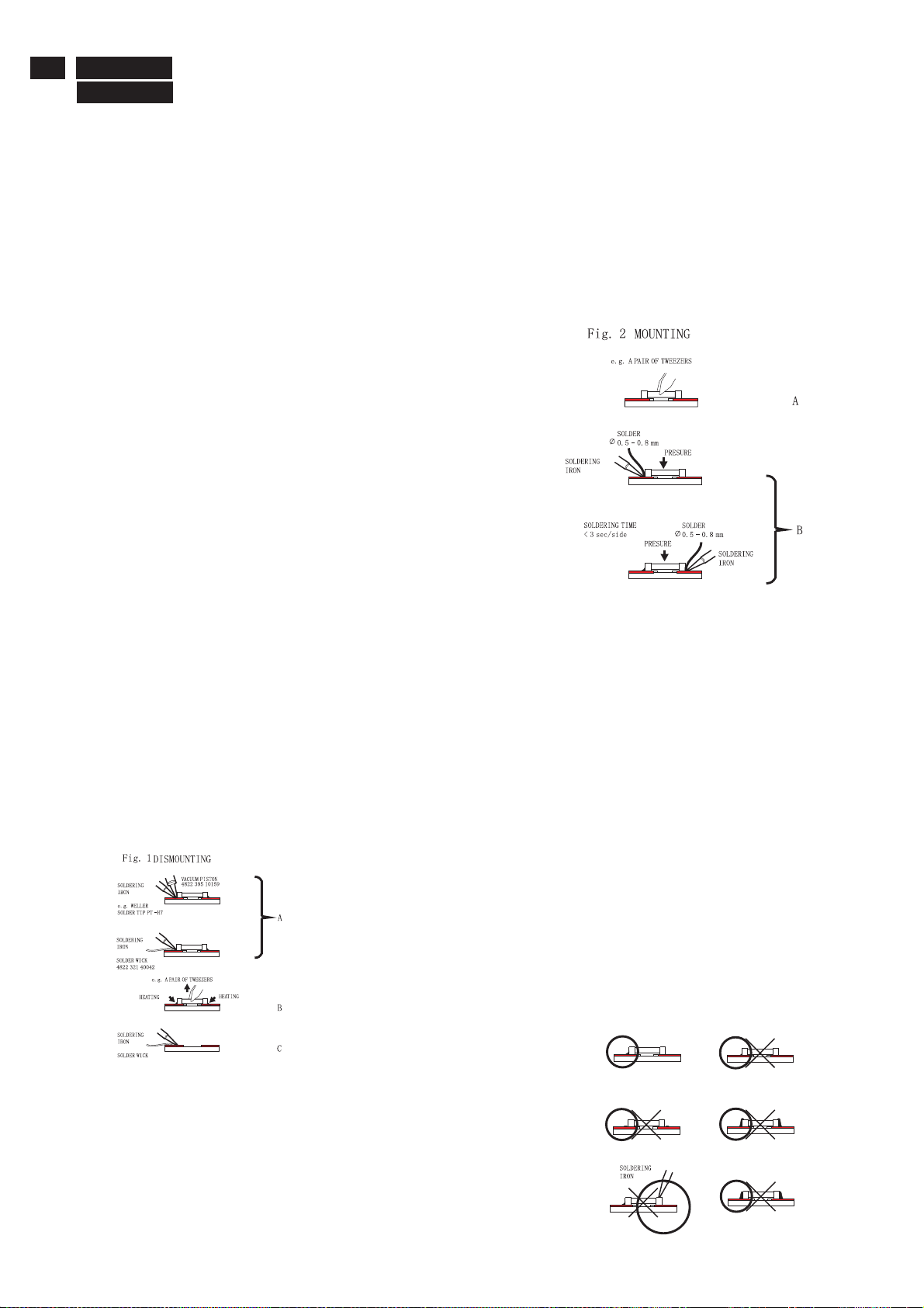
1. Servicing of SMDs (Surface Mounted Devices)
1.1 General cautions on handling and storage
- Oxidation on the terminals of SMDs results in poor soldering.
Do not handle SMDs with bare hands.
- Avoid using storage places that are sensitive to oxidation
such as places with sulphur or chlorine gas, direct sunlight,
high temperatures or a high degree of humidity. The
capacitance or resistance value of the SMDs may be
affected by this.
- Rough handling of circuit boards containing SMDs may
cause damage to the components as well as the circuit
boards. Circuit boards containing SMDs should never be
bent or flexed. Different circuit board materials expand and
contract at different rates when heated or cooled and the
components and/or solder connections may be damaged
due to the stress. Never rub or scrape chip components as
this may cause the value of the component to change.
Similarly, do not slide the circuit board across any surface.
1.2 Removal of SMDs
- Heat the solder (for 2-3 seconds) at each terminal of the
chip. By means of litz wire and a slight horizontal force,
small components can be removed with the soldering iron.
They can also be removed with a solder sucker (see Fig.
1A)
preferably be equipped with a thermal control (soldering
temperature: 225 to 250 C).
- The chip, once removed, must never be reused.
1.4 Attachment of SMDs
- Locate the SMD on the solder lands by means of tweezers
and solder the component on one side. Ensure that the
component is positioned correctly on the solder lands (see Fig.2A).
- Next complete the soldering of the terminals of the
component (see Fiq. 2B).
2. Caution when attaching SMDs
- When soldering the SMD terminals, do not touch them
directly with the soldering iron. The soldering should be
done as quickly as possible, care must be taken to avoid
damage to the terminals of the SMDs themselves.
- Keep the SMD's body in contact with the printed board when
soldering.
- The soldering iron to be used (approx. 30 W ) should
preferably be equipped with a thermal control (soldering
temperature: 225 to 250 C).
- Soldering should not be done outside the solder land.
- Soldering flux (of rosin) may be used, but should not be
acidic.
- After soldering, let the SMD cool down gradually at room
temperature.
- The quantity of solder must be proportional to the size of the
solder land. If the quantity is too great, the SMD might
crack or the solder lands might be torn loose from the
printed board (see Fig. 3).
While holding the SMD with a pair of tweezers, take it off gently using the
soldering iron's heat applied to each terminal (see Fig. 1 B).
- Remove the excess solder on the solder lands by means of
litz wire or a solder sucker (see Fig. 1C).
1.3 Caution on removal
- When handling the soldering.iron. use suitable pressure and be careful.
- When removing the chip, do not use undue force with the pair of tweezers.
- The soldering iron to be used (approx. 30 W) should
Right
Fig.3 Examples
Page 13

Repair Tips
3. Lead-free product identification
You can identify lead-free product by Philips-lead-free logo on PCB.
4. Lead-free product repair instruction
BDLx221/00
x2PM8822/xx
13
4.1 Use only lead-free Solder Alloy 0622 149 00106(1.2mm SAC305) or 0622 14900108(1.0mm SAC305).
Remark: For lead free soldering material, please visit website for details. This is recommended by Philips.
4.2 Use only adequate solder tools applicable for lead-free soldering-tin. The solder tool must be able to reach at least a
solder-temperature of 400 , to stabilize the adjusted temperature at the solder-tip and to exchange solder-tips for different applications.
Small Passives/Actives to be removed with thermal tweezers
Automated system for IC and BGA repair (Microscope, Camera, Beam split optics, Computer, Programmer, Heat controllers, Vacuum
system, Laser pointer) Solder Hand-Tool (Adjustable in temperature height, Temperature shall be held constant,Flexible tips)
4.3 Adjust your solder tool so that a temperature around 360 -380 is reached and stabilized at the solder joint.
Heating-time of the solder-joint should not exceed~4sec.Avoid temperatures above 400 otherwise wear-out of tips will rise drastically
and flux-fluid will be destroyed.Corrosion of Tool-Spikes can be avoided when using SAC305 and a temperature of less than 400 .
4.4 Mix of lead-free solder-tin/parts with leaded soldering-tin/parts is possible but not recommended. If not to avoid clean carefully the
solder-joint from old tin and re-solder with new tin.
4.5 Use only original spare-parts listed in the Service-Manuals. Standard-material(consumables) can also be purchased at external
companies.
www.alphametals.com
 Loading...