

Page 1

Published by JH 662 TV Service Printed in the Netherlands Subject to modification EN 3122 785 15652
©
Copyright 2006 Philips Consumer Electronics B.V. Eindhoven, The Netherlands.
All rights reserved. No part of this publication may be reproduced, stored in a
ret
rieval system or transmitted, in any form or by any means, electronic,
mecha
nical, photocopying, or otherwise without the prior permission of Philips.
Colour Television Chassis
ML1.2U LA
Description Page
Important Safety Notice -------------------------------2
General Product Specification(23") ------------- 2~27
On-sc
ree
n Display(OSD)------------------------ 18~29
Aging Mode ------------------------------------------- 30
Warning Message ------------------------------------ 31
Factory Mode ----------------------------------------- 32
Trouble Shooting -------------------------------------33
Panel Failure Mode ----------------------------------- 34
Wi
ring Diagram -------------------------------------- 35
Mechan
ical Instructions ------------------------ 36~37
Electr
ical Instructions -------------------------- 38~41
Di
splay Adjustments -------------------------- 42~43
Safety Test Requirement ---------------------------- 44
Description Page
DDC Instructions & DDC Data ------------------ 45~52
Firmware Upgrade for CPU ---------------------- 53~54
Func
tion Block Diagram---------------------------55~56
Direc
tion for User -------------------------------92~125
Scaler Schematic Diagram & C.B.A --------------57~72
Power Schematic Diagram & C.B.A --------------73~75
IR/HD Schematic Diagram & C.B.A --------------76~78
KEY Schematic Diagram & C.B.A ----------------79~80
Expl
oded View--------------------------------------- --81
Recommended/Spare parts list------------------82~86
Different Parts List ------------------------------------ 87
Repair Tips ---------------------------------------- 88~89
Repair Flow Chart -------------------------------- 90~91
ML1.2A LA
Page 2

2
Go to cover page
Proper service and repair is important to the safe,
reliable operation of all Philips Consumer Electronics
Company** Equipment. The service procedures
recommended by Philips and described in this service
manual are effective methods of performing service
operations. Some of these service operations require
theuseoftoolsspeciallydesignedforthepurpose.The
specialtoolsshouldbeusedwhenandas
recommended.
Itisimportanttonotethatthismanualcontains
various CAUTIONS and NOTICES which should be
carefully read in order to minimize the risk of personal
injury to service personnel. The possibility exists that
improper service methods may damage the equipment.
It is also important to understand that these
CAUTIONS and NOTICES ARE NOT EXHAUSTIVE.
Philips could not possibly know, evaluate and advise
theservicetradeofallconceivablewaysinwhich
service might be done or of the possible hazardous
consequences of each way. Consequently, Philips has
not undertaken any such broad evaluation. Accordingly,
aservicerwhousesaserviceprocedureortoolwhich
is not recommended by Philips must first satisfy
himself thoroughly that neither his safety nor the safe
operationoftheequipmentwillbejeopardizedbythe
service method selected.
ME5P 23"
Important Safety Notice
TO ENSURE THE CONTINUED RELIABILITY OF THIS
PRODUCT, USE ONLY ORIGINAL MANUFACTURER'S
REPLACEMENT PARTS, WHICH ARE LISTED WITH
THEIR PART NUMBERS IN THE PARTS LIST SECTION
OF THIS SERVICE MANUAL.
Take care during handling the LCD module with
Backlight unit
- Must mount the module using mounting holes
arranged in four corners.
-Donotpressonthepanel,edgeoftheframe
stronglyorelectricshockasthiswillresultin
damage to the screen.
-Donotscratchorpressonthepanelwithanysharp
objects,suchaspencilorpenasthismayresultin
damage to the panel.
- Protect the module from the ESD as it may damage
the electronic circuit (C-MOS).
- Make certain that treatment person s body are
grounded through wrist band.
-Donotleavethemoduleinhightemperatureandin
areasofhighhumidityforalongtime.
-Avoidcontactwithwaterasitmayashortcircuit
within the module.
- If the surface of panel become dirty, please wipe it
offwithasoftmaterial.(Cleaningwithadirtyor
rough cloth may damage the panel.)
* *Hereafter throughout this manual, Philips Consumer
Electronics Company will be referred to as Philips.
WARNING
Critical components having special safety
characteristics are identified with a by the Ref. No.
in the parts list and enclosed within a broken line*
(where several critical components are grouped in one
area)alongwiththesafetysymbol onthe
schematics or exploded views.
Use of substitute replacement parts which do not have
the same specified safety characteristics may create
shock, fire, or other hazards.
Under no circumstances should the original design be
modified or altered without written permission from
Philips. Philips assumes no liability, express or implied,
arising out of any unauthorized modification of design.
Servicer assumes all liability.
*BrokenLine
FOR PRODUCTS CONTAINING LASER :
DANGER-
CAUTION-
CAUTION-
Invisible laser radiation when open.
AVOID DIRECT EXPOSURE TO BEAM.
Use of controls or adjustments or
performance of procedures other than
those specified herein may result in
hazardous radiation exposure.
The use of optical instruments with this
product will increase eye hazard.
Page 3
Me5P 15" & 20"
GENERAL PRODUCT SPECIFICATION
ME5P 23"
Go to cover page
GENERAL PRODUCT SPECIFICATION
. 23”Multifunction LCD monitor
. PC 15 pins D-SUB analog interface
. PC audio line in withmini-Jack
. TV Tuner, S-Video, RCA AV input/output interface with R/L Audio-in
. DVI digital interface with HDCP support (for TV only)
. RCA connectorsfor YPbPr input
3
. HD/Component YPbPr with
L/R audio input (RCA connector)
. NTSC, PAL TV system
. PC graphicauto picture adjustment
. 14user modes
. User-friendly OSD menu
. User-friendly remote controller
. Recommend resolution 1280 x 768 non-interlace at 60Hz
. WXGA 23”col
or TFT LCD flat panel
. Easy tilt base
. Anti-glare to reduce lightreflection
. Power management capability
. VESA standard wall mount kit (option)
2005-07-01
Yikuan YU
23
" Wide LCD Monitor/TV
BRAND: PHILIPS
2005-07-01
25
590
1
Page 4

4
Go to cover page
ME5P 23"
GENERAL PRODUCT SPECIFICATION
CONTENTS
1.0Foreword
2.0Productprofile
2.1LCD
2.2Scanningfrequencies
2.3 Video dot rate
2.4 Power input
2.5Power consumption
2.6 Dimensions
2.7Weight
2.8 Side speaker
2.9Functions
2.10 Ambient temperature
2.11 Regulatorycompliance
3.0Electrical characteristics
3.1 Interfacesignals cables
3.2 User interface
3.2.1 Keypaddefinition
3.2.2 Key Function definition
3.2.3Remote control
3.3PC, TV requirement
3.3.1 PC interface
3.3.1.1Modestoringcapacity
3.3.1.2 Horizontalscanning
3.3.
1.3 Verticalscanning
3.3.1.4 Input connectors
3.3.1.5Available timings
3.3.2 I/O interface
3.3.2.1TVspecial setting
3.3.3Electriccharacteristicsof I/O
3.3.3.1PCSignaltype
3.3.3.2TVSignaltype
3.3
.3.3PVRoutput (CVBS output)
3.4 Power input connection
3.5Power management
2005-07-01
Yikuan YU
23" Wide LCD Monitor/TV
BRAND: Philips
2005-07-01
25
590
2
Page 5

Me5P 15" & 20"
GENERAL PRODUCT SPECIFICATION
4.0Visual characteristics
4.1Test conditions
4.2PCresolution
4.3Brightness
4.4 Image size
4.4.1Actual display size
4.5Brightness uniformity
4.6 PC white color adjustment
4.7TVwhite color adjustment
4.8 TV picture centering
5.0Mechanical characteristics
5.1 Controls
5.2Unitdimension / weight
5.3Tilt and swivelbase
5.4 Transportation packages
5.4.1Shipping dimension / weight
5.4.2Block unit / palletization
ME5P 23"
Go to cover page
5
6.0Environmental characteristics
6.1Susceptibility of display to external environment
6.2Transportation tests
6.3Display disturbancesfrom external environment
7.0Reliability
7.1Meantime between failures
8.0 Quality assurancerequirements
8.1Acceptancetest
9.0Serviceabilit y
23
" Wide LCD Monitor/TV
2005-07-01
Yikuan YU
BRAND: PHILIPS
2005-07-01
25
590
3
Page 6
6
Go to cover page
ME5P 23"
1.0 FOREWORD
2.0 PRODUCT PROFILE
GENERAL PRODUCT SPECIFICATION
This specification describes a 23”multifunction LCD Monitor,maximum
resolution upto1280x768/60Hz non-interlaced.
This 23” TFT LCD monitor/TV can connecttoPC‘s analog D-SUB and
TV’sdigitalsignalthroughDVI-Dconnector and it also haveTV,
Composite Video, S-Video, Component YPbPr , PVR output and HD
YPbPr interface.
2.1LCD
2.1.1.QDI panel
Type NR. : QD23HL02 (QDI panel)
Display area(mm) :508.152mm x 285.696mm
Number of Pixels : 1366(H) x 768(V)
Pitch (mm) :0.372(H) x 0.372(V)
Color pixel arrange ment : RGB verticalstripe
Display operatingmode : Normallywhite
Color depth : 16,7 million color
Brightness (cd/m^2) : 500(Center 1 points, Typ.)
Viewingangle(CR>10)
65/60(Typ.))
Surfacetreatment : Hard coating(3H),Anti-glare treatment of the
front polarize
Electrical interface:LVDS
Response Time(ms, Typ) :TrR:6,TrF:10
Contrast ratio : Typical450:1
Outline Dimension : 546.0mm(H) x 318(V
Module weight (g) : 3300(Typ.)
Backlight : 6 CCFT
:Viewingangle free(R/L 70/70(Typ.),U/D
)(Typ.)
2.2Scanningfrequencies : Hor. :30-50KHz Ver.:56 - 63 Hz
2.3Videodotrate : <80MHz
2.4Power input:90-264Vac, 50/60 ± 2 Hz
2.5Power consumption : 75 W/Typ.(atPCmode ),95 W/Typ.(atTVmode ).
2.6 Unit Di
mensions : 615 mm W x 234 mm H x 318mmD (Incl. Pedestal)
2.7 Unit Weight : 11.2 Kg
2.8 Chin speaker : 2 x 5W
23" Wide LCD Monitor/TV
2005-07-01
Yikuan YU
BRAND: Philips
2005-07-01
25
590
4
Page 7
Me5P 15" & 20"
GENERAL PRODUCT SPECIFICATION
2.9Functions :
PC -15 pins D-sub analog interface withaudio mini-Jack input (PC line in)
TV -DVI-D Digital interface (Support HDCP)with RCA jack L/R audio input.
-Tuner, Aerial input.
-Component YPbPr input and Composite Video input share with the
same audio.
-HD/Component YPbPr input and audio input with RCA jack.
-Composite video input and S-Video input share with t
-PVR output (Composite Video and Audio output).
2.10 Ambient temperature: 5 ~ 35 °C
2.11 Regulatorycompliance:
ME5P 23"
Go to cover page
.
he same audio.
7
International Regulatory Specification
COUNTRYDOM
AIN
NAFTA +
LATAM
Sa
USA
Canda
Panama
Colombia
Ecuador
Venezuela
Chile
Peru
E
O Energy Star
Sa
E
Sa UL6500 /IEC60065UL
E NO NA
SAFETY /EMC/ERGONOMICS/
STANDARDS
UL6500 UL
FCC Part15
UL6500 cUL
FCC Part15
DOCUMENTS
FCC DOC or FCC ID /
Verification
EPA registration
FCC DOC or FCC ID /
Verification
2005-07-01
Yikuan YU
23
" Wide LCD Monitor/TV
BRAND: PHILIPS
2005-07-01
25
590
5
Page 8

8
ME5P 23"
Go to cover page
Bolivia
Argentin
a
Paragua
y
Uruguay
Mexico
AP
CB
report
e
Kong
Malaysia
a
India
Thailand
East
GENERAL PRODUCT SPECIFICATION
Sa
E
CISPR 13 , CISPR 20,IEC61000-3-2
Sa
E NO
Sa UL6500 /IEC60065
E NO
NOM-001-SCFI-1993(derived from IEC 60065: 5th
Sa
E CISPR 13 , CISPR 22
Sa
IEC60065: nationaldifferences ofall countries
Sa IEC60065Singapor
E NO
Sa IEC60065Hong
E CISPR 13
Sa IEC60065 (MS72)
E CISPR 13
Sa IEC60065Indonesi
E NO
Sa IEC60065
E NO
Sa IEC60065 (TIS 1195-2536 )
E
Sa IEC60065Middle
E CISPR 13
IEC60065 (IRAM4029)
UL6500 /IEC60065
ed.+Amd.2&3)
NO
IRAM + SICM
NA
NA
NOM -NYCE
CB Report
PSB
Declaration Of Conformity
SIRIM
NA
NA
Register with Thai
IndustrialStandards
Institute (TISI)
SASO Registration / KSS
Registration
2005-07-01
Yikuan YU
23" Wide LCD Monitor/TV
BRAND: Philips
2005-07-01
25
590
6
Page 9
8
ME5P 23"
Go to cover page
Bolivia
Argentin
a
Paragua
y
Uruguay
Mexico
AP
CB
report
e
Kong
Malaysia
a
India
Thailand
East
GENERAL PRODUCT SPECIFICATION
Sa
E
CISPR 13 , CISPR 20,IEC61000-3-2
Sa
E NO
Sa UL6500 /IEC60065
E NO
NOM-001-SCFI-1993(derived from IEC 60065: 5th
Sa
E CISPR 13 , CISPR 22
Sa
IEC60065: nationaldifferences ofall countries
Sa IEC60065Singapor
E NO
Sa IEC60065Hong
E CISPR 13
Sa IEC60065 (MS72)
E CISPR 13
Sa IEC60065Indonesi
E NO
Sa IEC60065
E NO
Sa IEC60065 (TIS 1195-2536 )
E
Sa IEC60065Middle
E CISPR 13
IEC60065 (IRAM4029)
UL6500 /IEC60065
ed.+Amd.2&3)
NO
IRAM + SICM
NA
NA
NOM -NYCE
CB Report
PSB
Declaration Of Conformity
SIRIM
NA
NA
Register with Thai
IndustrialStandards
Institute (TISI)
SASO Registration / KSS
Registration
2005-07-01
Yikuan YU
23" Wide LCD Monitor/TV
BRAND: Philips
2005-07-01
25
590
6
Page 10
10
Go to cover page
ME5P 23"
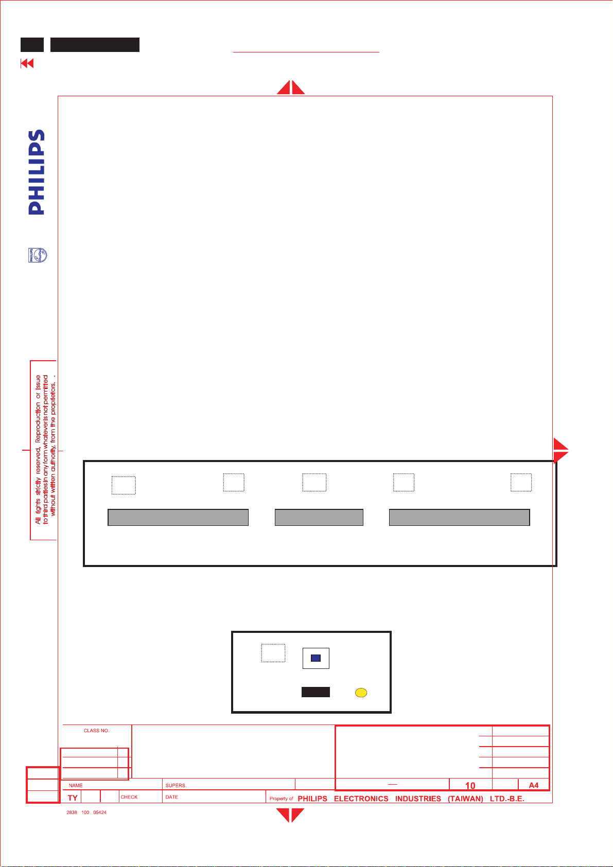
3.2 User interface
GENERAL PRODUCT SPECIFICATION
Length : 1.5M+/- 50 mm
AV cable (option)
Length : 1.5M +/- 50 mm
Mini Jack stereo cable (option)
Length : 1.5M+/- 50 mm
YPbPr cable (option)
Length : 1.5M +/- 50mm
Power cord
Length : 1.8M+/- 50 mm
On screen display user control viakeypad and remote control for PC
and TV OSD.
3.
2.1 Keypaddefinition
B
- Volume +
Top Control
Panel
C D E F
Menu
RightLeft
- Channel +
Front Control
Panel
A
Power SW
RC sensor
Power
LED
UpDown
2005-07-01
Yikuan YU
23" Wide LCD Monitor/TV
BRAND: Philips
2005-07-01
25
590
8
Page 11
Me5P 15" & 20"
GENERAL PRODUCT SPECIFICATION
ME5P 23"
Go to cover page
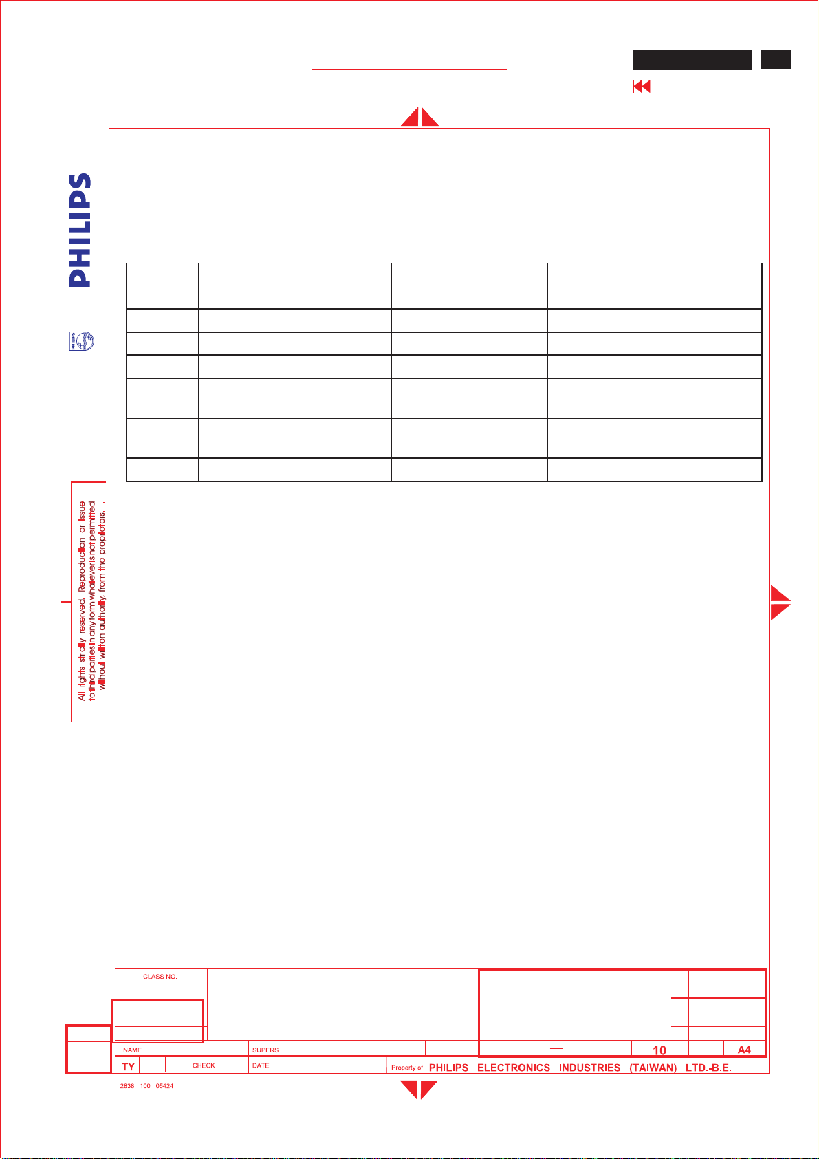
3.2.1 Key Function definition:
Key Function VGA mode TV/video mode
<A> Power DC Power DC Power
<B> LeftLeft/VolumedownLeft/Volumedown
<C> RightRight/Volume up Right/Volume up
<D> Menu Enter /Exit OSD
Enter /Exit OSD menu
menu
<E> Menu Down/channel
Menuline DownMenu Down/Channel Down
down
<F> Menu Up/Channelup Menuline Up Menu Up/Channelup
11
1. Press “MENU”key to call main menu.
2. By“Up/Down”to select function and “Left/Right”to adjust.
3.“Left/Right”alsois VolumeHotKey(TV and PC mode).
4. “Up/Down”alsois Channel Hot Key(TV mode).
5. Press hot Key<
B>and <C>can auto-adjust picture position, phase and clock in
PC mode.
Power LED:
Normal working: Green
Power saving:Red
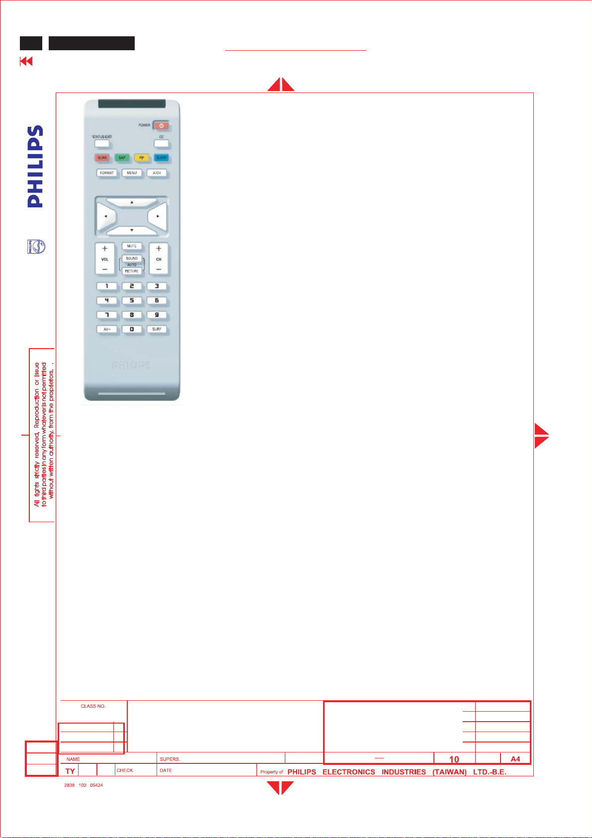
3.2.2Remote control
2005-07-01
Yikuan YU
23
" Wide LCD Monitor/TV
BRAND: PHILIPS
2005-07-01
25
590
9
Page 12
12
Go to cover page
ME5P 23"
GENERAL PRODUCT SPECIFICATION
1.Power : Power On/Standby
2.Numerica keys:(0~9),Channel setting
3.Mute : Sound mute function
4.Prev-CH :Recall previousCH
5.Menu :Main menu select and OKkey
6.VOL- : Left/VolumeDown
7.OK :nokey define
8.Source:Sourcesele
9.Closed cap. :Closedcaption on/off
10.SAP(2
11.CH-:Down/Channel Down
12.PIP : PIP sizeselect (Small/Medium/Large/PBP)
13.VOL+ :Right/VolumeUp
14.CH+ :Up/Channel Up
15.Display Format:Selectdisplay format
16.Smart Sound : Selectsound effect
17.Smart Picture : Selectpicture effect
8.Sleep Timer : Sleep timer 15,30,60,120,180,240OFF
1
nd
audio) :Sound select
ct
All PC or TV OSD menufunction could be accomplished by remote control.
3.3PCand TV requirement
3.3.1 PC interface
3.3.1.1Modestoringcapacity
Pre-set : 6
User modes : 8
3.3.1.2 Horizontalscanning
Sync polarity :PositiveorNegative
Scanningfrequency :30-50KHz
3.1.3 Verticalscanning
3.
Sync polarity :PositiveorNegative
Scanningfrequency :56 - 63 Hz
3.3.1.4 Input connectors
23" Wide LCD Monitor/TV
2005-07-01
Yikuan YU
BRAND: Philips
2005-07-01
25
590
10
Page 13
Me5P 15" & 20"
GENERAL PRODUCT SPECIFICATION
Input analog D-sub connector pin assignment
PIN
No.
-1.8m 15Pins, D-sub male with DDC2B Pin assignments.
SIGNAL b(PC)
1Red
2 Green
3Blue
4 Self test
5GND
6 Red GND
7 Green GND
8 BlueGND
9 +5V (Supply from PC)
10 Sync GND
11 GND
12 Bi-directional data
13 H-sync
14 V-sync
15 Dataclock
ME5P 23"
Go to cover page
13
3.3.1.5Availabletimings
Factorypre-set timing, size and centeringare according to thereference
timingcharts, The listisasbelow:
MODE NO. 123
RESOLUTION 640 x480 800 x600 800 x600
Dot clock(MHz) 25.175 36.000 40.000
fh 31.469kHz 35.156kHz 37.879kHz
A (us) 31.778(800 dots) 28.44 (1024 dots) 26.40 (1056 dots)
B (us) 3.813 ( 96 dots) 2.000 ( 72 dots) 3.200 ( 128 dots)
C (us) 1.907 (48dots) 3.556(128 dots) 2.200 (88dots)
D (us) 25.422 (640dots) 22.22 (800 dots) 20.00 (800 dots)
E (us) 0.636(16 dots) 0.667 ( 24 dots) 1.000 (40dots)
fv 60Hz(59.940 ) 56Hz(56.25 )60Hz( 60.317)
O (ms ) 16.683 (525 lines)17.78(625 lines) 16.58(628lines)
P (ms) 0.064 ( 2 lines) 0.057 ( 2 lines) 0.106(4lines)
Q(ms) 1.049 ( 33 lines) 0.626(22 lines) 0.607 ( 23 lines)
R (ms) 15.253 (480 lines)17.07 (600 lines) 15.84 (600 lines)
S (ms) 0.317 ( 10 lines) 0.028(1 line ) 0.026(1 line )
SYNC. H/V - / - + / ++/ +
POLARITY
SEP . SYNC YYY
2005-07-01
Yikuan YU
23
" Wide LCD Monitor/TV
BRAND: PHILIPS
2005-07-01
25
590
11
Page 14
14
Go to cover page
ME5P 23"
GENERAL PRODUCT SPECIFICATION
MODE NO.4 5 6
RESOLUTION 1024x768 1280X720 1280 x 768
CVT CVT
Dot clock(MHz) 65.000 74.579.50
f h 48.363kHz 44.772kHz 47.776kHz
A (us ) 20.677(1344 dots) 22.336(1664 dots) 20.931(1664 dots)
B (us ) 2.092(136 dots) 1.718(128 dots) 1.610(128 dots)
C (us ) 2.462(160dots) 2.577(192 dots) 2.415(192 dots)
D (us ) 15.754(1024 dots) 17.181(1280dots) 16.101(1280dots)
E (us ) 0.369(24 dots) 0.859(64 dots) 0.805(64 dots)
fv 60Hz (60.004) 60Hz (59.855)60Hz (59.87)
O (ms ) 16.666(806 lines) 16.707(748 lines) 16.703(798 lines)
P (ms ) 0.124(6 lines) 0.111678(5 lines) 0.1455(7 lines)
Q(ms ) 0.600(29 lines) 0.4467(20 lines) 0.4186(20 lines)
R (ms ) 15.880(768 lines) 16.082(720 lines) 16.075(768 lines)
S (ms ) 0.062(3 lines) 0.067(3 lines) 0.0628(3 lines)
SYNC.H/V -/- -/+ -/+
POLARITY
SEP . SYNC YY Y
A: H-TotalO:V-Total
B: H-Syncwidth P: V- Syncwidth
C: H-Back porch Q:V-Back porch
D: H- Video width R: V- Video length
E: H- Front porch S: V- Front porch
3.3.2 I/O interface
Connect:
1. Tuner: RTMA M/N system reception.
2. DVI IN: DVI input (TV digitalsignalsupport HDCP)with audio R/L.
3. PC IN: VGA input (D-SUB connec
tors)with audio R/L(mini-jack).
4. HDIN:HDTV input with YPbPr format and audio R/L(RCA jack).
5. AV IN2: Component video YPbPr and composite video(Video 2)
share with same audio R/L.
6. AV OUT: Composite video output (CVBS)and audio R/L(RCA jack).
7. AV IN1: Video1 (CVBS)and S-Video 1 share with same audio R/L.
2005-07-01
Yikuan YU
23" Wide LCD Monitor/TV
BRAND: Philips
2005-07-01
25
590
12
Page 15
Me5P 15" & 20"
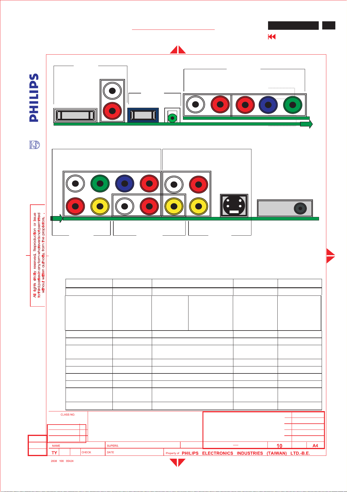
Location:
DVI
(HDC
P)
L
GENERAL PRODUCT SPECIFICATION
DVI IN
AUDIO
L
R
AUDIO
PC IN
VGA
Fig. 21
COMP VIDEO AUDIO
YPb Pr L R
AUDIO COMP
VIDEO
L R Pr Pb Y
HD IN
ME5P 23"
Go to cover page
TUNER
15
R
Video 2 L R VIDEO Video1 S-
VIDEO
AV IN 2 AV OUT AV IN 1
Fig. 22
Following tableis thedeviation ofmain TV system.
Item WEUROPE America AP China
TV Color system PAL, SECAM NTSC PAL/NTSC PAL
Tuner
FQ1216ME5
Picture carrier
38.9MHz
V system B/G, D/K, I, LM B/G, NTSC-M D/K
Sound decoder MSP3410G MSP3440G MSP3410G MSP3410G
CVBS,YC
Multi Multi Multi Multi
Color system
Scaler MCU WE version NAFTA version AP version Chinaversion
Closed caption N Y NN
V-chip N Y NN
TeletextN N N N
Remote
controller(RC5)
Europe
version
Channel number 100 US Air 68, cable125 100 100
FQ1236/F H5
Picture
FQ1216ME/H5
Picture carrier
38.9MHz
FQ1256/I
Picture carrier
38MHz
carrier
45.75MHz
NAFTA version AP version CHINA version
2005-07-01
Yikuan YU
23
" Wide LCD Monitor/TV
BRAND: PHILIPS
2005-07-01
25
590
13
Page 16
16
Go to cover page
ME5P 23"
Following table is the detail TV System list.
GENERAL PRODUCT SPECIFICATION
TV
system
M
N4.5 BTSC-stereo SAP PAL Argentina
B/G
L 6.5/5.85 AM-Mono/NICAM SECAM-L France
I 6.0/6.552 FM-Mono/NICAM PAL GreatBritain,
D/K
Position of sound
carrier
(MHz)
4.5/4.724212 FM-Stereo (A2) NTSC Korea
4.5FM-FM(EIA-J) NTSC Japan
4.5 BTSC-stereo SAP NTSC USA
5.5/5.7421875 FM-stereo (A2) PAL Germany,
5.5/5.85 FM-Mono/NICAM PAL Belgium, Spain,
6.5/6.2578125 FM-Stereo
6.5/6.7421875 FM-Stereo
6.5/5.7421875 FM-Stereo
6.5/5.85 FM-Mono/
Sound system Color
system
SECAM-
(A2, D/K1)
(A2, D/K2)
(A2, D/K3)
NICAM (D/K, NICAM)
East
PAL None
SECAMEast
PAL China, Hungary
Country
Austria,
Switzerland,
Italy,
Netherlands.
Denmark,
Finland,
Norway,
Sweden.
HongKong,
Ireland.
Slovak. Rep.
Poland
3.3.2.1TVspecial setting
Close Caption, V-chip (NAFTA Tuner, CVBS inputsource only)
3.3.3Ele
ctriccharacteristicsof I/O
3.3.3.1PCSignaltype
Analog Video : 0.7 Vp-p linear, positive polarity
Separate Sync. : TTL level, separate, positiveornegativepolarity
Audio signal:Mini-jack audio input,
23" Wide LCD Monitor/TV
2005-07-01
Yikuan YU
BRAND: Philips
- CC-1, CC-4 decodingand display
-TXT1, TXT4 Text mode
-NoExtended Data Services (EDS)
-Support violenceratingand checking
-Automatic CC-1 selection at user mute
Level: Nominal:0.5Vrms.
Maximum :1.5Vrm
s.
Impedance > 10 k ohm
25
2005-07-01
590
14
Page 17
Me5P 15" & 20"
)
GENERAL PRODUCT SPECIFICATION
ME5P 23"
Go to cover page
Signal source:pattern generator format as attachment.(table1to6)
Reference generator: CHROMA 2200 or 2250
3.3.3.2TVSignal type
RF signal :Aerial input/10mV(80dBuV)
Video signal :Video( RCA CVBS input) /1Vpp (300mV-sync, 700mV-video.
S video input/1VppY-signal, 300mVpp C-signal
COMP Video(YPbPr input)/1Vpp Y signal, 350mVpp Pb,Pr signal
DVI : Digital interface with4channels TMDS signal
Audio signal :Audio (1) R/L for AV IN1 (Video1 and S-video).
Level:Nominal :0.5Vr
ms.
Maximum :1.5Vrms.
Impedance > 10 k ohm.
Audio (2) R/L for AV IN3 (Video2 and Comp video).
Level:Nominal :0.5Vrms.
Maximum :1.5Vrms.
Impedance > 10 k ohm.
Audio (3) R/L for DVI IN.
Level:Nominal :0.5Vrms.
Maximum :1.5Vrms.
Imp
edance > 10 k ohm.
17
3.3.3.3 PVR output (CVBS output)
Video: CVBS output1Vpp /Impedance:75ohm.
Audio: R/L output (from CVBS)
Level:Nominal :0.5Vrms.
Maximum :1.5Vrms.
Impedance < 1 k?
3.4 Power input connection
Power cord l
ength :1.8 M
Power cord type:3leadspower cord withprotectiveearthplug.
3.5Power management
PC mode
The power consumption and the status indication of the set
withpower management function are as follows:
Power Spec
2005-07-01
Yikuan YU
23
" Wide LCD Monitor/TV
BRAND: PHILIPS
2005-07-01
25
590
15
Page 18
18
Go to cover page
ME5P 23"
GENERAL PRODUCT SPECIFICATION
STATUS Horizontal Vertical 230V
AC
LED
On Pulse Pulse Typical 75W Green
Stand-by No Pulse Pulse < 1W Red
Suspend Pulse No Pulse < 1W Red
Off No Pulse No Pulse < 1W Red
Power switchoff -- < 1W -
TV mode
The power consumption and the statusindication of the set
with power management function are as follows,
Power Spec
STATUS 230V
AC
LED
On Typical 95W Green
Stand-by < 1W Red
Power switchoff < 1W -
In Monitor power savingmode
,
WhichnoH&Vsync or absent either H-sync or V-sync input via VGA connector.
The monitor will enter “Monitor savingmode”. The way to wake uporchange
source:
1.H-syncand V-sync havesignal again.
2. Press “AV”key on remote control,chang
etovideo sourcedirectlyvia OSD tree.
In TV power savingmode
,
Whichswitched off by RC “Power”key, SLEEP TIMER function or no TV signal
input for 30 minutes, the monitor will enter “TV standby mode”and LED shows
Red color. The way to wake up:
Press “Power”key on remote control to return original video source.
4.0Visual characteristics
4.1Testconditions
Unless otherwise specified, this specification is defined under the following
conditions.
(1) Inputsignal:Asdefined in 3.3.1.5, 1280 x 768x60Hz
non-interlaced mode (47.776kHz), signal
sources must have75ohm outputimpedance.
(2) Lumin
ance setting: controls to be set to 500 Nits (typical)with
23" Wide LCD Monitor/TV
full screen 700mv white signal.
2005-07-01
Yikuan YU
BRAND: Philips
2005-07-01
25
590
16
Page 19
Me5P 15" & 20"
GENERAL PRODUCT SPECIFICATION
(3) Warmup: more than30minutesafter power on withsignal supplied.
(4) Ambient light: 400 ~600 lux.
(5) Ambient temperature: 25 ± 2 °C
4.2PCResolution
Resolution Frequency Pixel rate Sync Comment
1 640X48031.469K/59.94Hz
2 800X600 35.156K/56.25Hz 36MHz(+/+) VESA
3 800X600 37.879K/60.317Hz40MHz(+/+) VESA
4 1024X768 48.363K/60.004Hz65MHz(-/-) VESA
51280X720 44.772K/59.855Hz 74.5MHz(-/+) CVT
6 1280X768 47.776K/59.87Hz 79.5MHz(-/+) CVT
25.175MH
z
(-/-) IBM VGA
ME5P 23"
Go to cover page
19
4.3Brightness
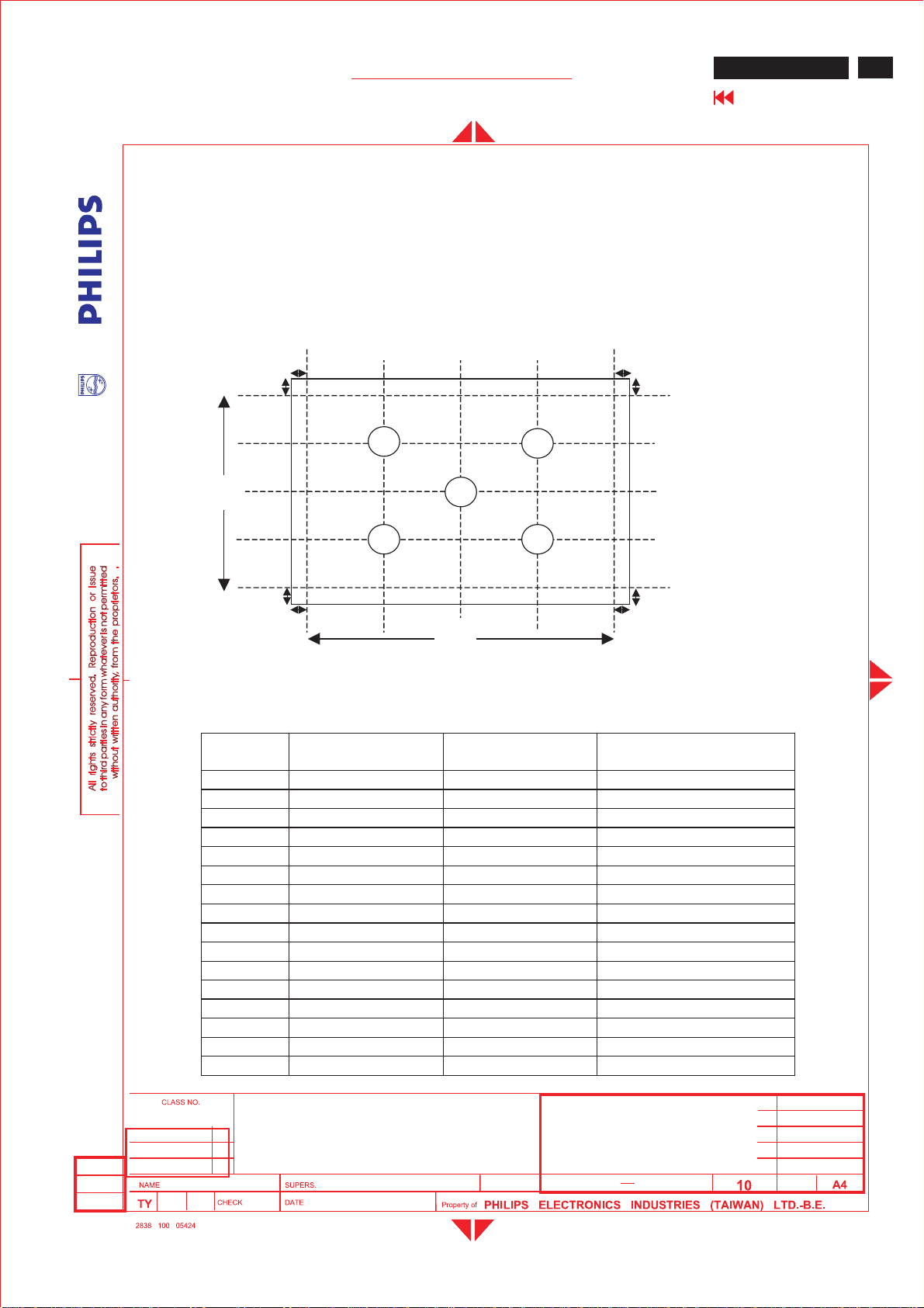
>400 nitsat maximum contrast and Brightness. (At center of the screen, Fig. 1)
4.4 Image size
4.4.1Actual display size508.125mmx285.696mm
4.5Brightness uniformity
Set contrast at 100%and turn the brightness to Max. (At original color)
A
pply theFig 1, it should comply with the followingformula:
Maximum luminanceoffive points(brightness)
¾¾¾¾¾¾¾¾¾¾¾¾¾¾¾¾¾¾¾¾ <1.3
Minimum luminanceoffive points(brightness)
4.6 PC White color adjustment
Apply 1280x768@60Hzmode set sma
rt picture to “Normal”,
Apply full white pattern,withbrightness in 90 %position and the contrast control
at50%position.
The 1931 CIE Chromaticity(color triangle) diagram (X, Y)
coordinate for the screen center should be:
8500K CIE coordinatesX=0.292 ± 0.030
Y=0.293 ± 0.030
2005-07-01
Yikuan YU
23
" Wide LCD Monitor/TV
BRAND: PHILIPS
2005-07-01
25
590
17
Page 20

20
Go to cover page
ME5P 23"
4.7 TV White color adjustment
GENERAL PRODUCT SPECIFICATION
Smart picture set to personal for TV RF signal (80dBmv).
Use FLUKE54200 pattern generator with full white pattern.
Use The 1931 CIE Chromaticity(color triangle) diagram (X, Y) coordinate for
the screen
center should be: X=0.292+/-0.030,Y=0.293+/-0.030.
4.8TVpictu
re centering
Use CVBS (PAL and NTSC) input with cross hatchpattern to check the picture
centeringand should be
Left (size)-Right (size)<± 2mm.
Up (size)-Down (size)<± 2mm.
5.0Mechanical characteristic
5.1 Controls
Top Control :
-Upkey
-Down key
-Menukey
-Right key
-Left key
Front - RC sensor
-DCpower switch
RearI/O :
- AC inlet
-DVI(Support HDCP) input
- L/R audio input for DVI
-PCD-sub
-Minijack PC audio input
- L/R audio input for HD
- YPbPr video input for HD
-Tuner RF input
- S-Video1 input
-Com
- L/R audio input
-Composite video output
- L/R audio output
- YPbPr video input for component
-Composite video input (Video 2)
- L/R audio input
posite video input (VIDEO 1)
(S-video1 and Video1 share with same audio)
2005-07-01
Yikuan YU
23" Wide LCD Monitor/TV
BRAND: Philips
2005-07-01
25
590
18
Page 21

Me5P 15" & 20"
GENERAL PRODUCT SPECIFICATION
(Component and Video 2 share withsame audio
5.2Unitdimension/Weight
Set dimension (incl. pedestal): 615 mm W x 234mmH x 318mmD
Net weight:11.2 Kg
5.3Tilt base
Tilt angle:0to10degree
5.4 Transportation packages
5.4.1Shipping dimension/Weight
rton dimension : 672 mm W x 550 mm H x 308mmD
Ca
Gross weight:14Kg
5.4.2Block unit / Palletization (Seashipment)
Container
346 212
Detailpleaserefer to sheet 560
layers/block sets/layer sets/block unit
ME5P 23"
Go to cover page
21
6.0Environmental characteristics
The followingsections define the interference and susceptibilitycondition limits
that mightoccur between external environment and thedisplay device.
6.1Susceptibility of display to external environment
Operatin
Storage
Shipping -Temperature :( -20to50
g
-Temperature :0to40
-Humidity :10to95%(non –condensing)
-Altitude : 0 to 12000 feet
-Airpressure : 600 to 1100 mBAR
- (guaranteed optical performance):5to35
- (guaranteed functional performance):5to40
-Temperature : -20 to 50
-Humidity :10to95%(non –condensing)
-Airpressure : 600 to 1100 mBAR
Note: recommend at0to35°C, Humidityless than 60 %
-Humidity : 10to95%(non –condensing)
)
2005-07-01
Yikuan YU
23
" Wide LCD Monitor/TV
BRAND: PHILIPS
2005-07-01
25
590
19
Page 22
22
Go to cover page
ME5P 23"
GENERAL PRODUCT SPECIFICATION
- Altitude :0to40000 feet ( non operating)
- Air pressure : 600 to 1100 mBAR
6.2Transportation tests
Standard UAN-D1534/01
Height Bottom45 &other 25 cm
Bottomx3
Left,front side, right, back, top
Drop Sequence
Test
Electrical function ok
Test Mechanical function ok
Result No seriousdamageonsetappearance
(room temp./-10°c,humidity 70 %)
Sequence --- PACKAGING sine vibration
Vibration - frequency:7HZ,
- acceleration:1.05g
- test duration : 30 min.
- direction: Y transport direction only
Test Test Electrical function ok
Result Mechanical function ok
No seriousdamageonsetappearance
Detail follow the UAN-D1534/01
6.3 Display disturbances from externalenvironment
According to IEC 801-2 for ESD disturbances
7.0Reliability
7.1MeanTimeBetween Failures
System MTBF (Excluding the LCD panel and CCFL) :50,000 hrs
CCFL MTBF : 50,000 hrs
8.0 Qualityassurancerequir ements
8.1Acceptance test
According to MIL-STD-105D Control II level
AQL:0.65 (major) 2.5 (minor)
(Please also refer to annual qualityagreement)
8.2
Cosmeticand dot defectof panel refer to the IIS
specification of panel.
23" Wide LCD Monitor/TV
2005-07-01
Yikuan YU
BRAND: Philips
2005-07-01
25
590
20
Page 23
Me5P 15" & 20"
GENERAL PRODUCT SPECIFICATION
9.0Serviceability
The serviceability of thismonitor should fulfill the
requirementswhich are prescribed in UAW-0346 and must be checked
with the check listUAT-0361.
Fig 1: Brightness and Uniformitymeasure points
H/4
b
a
1
V
H/2
5
3H
/4
2
ME5P 23"
Go to cover page
b
23
a
V/
4
V/2
1
a
b
Table1.
NAFTA TV Channels
US- Air broadcast channel
Broadcast
Channel
255.25 59.75 54-60
3 61.25 65.75 60-66
467.25 71.75 66-72
577.25 81.75 76-82
683.25 87.75 82-88
7 175.25 179.75 174-180
8 181.25 185.75 180-186
9187.25 191.75 186-192
10 193.25 197.75 192-198
11 199.25 203.75 198-204
12 205.25 209.75 204-210
13 211.25 215.75 210-216
14471.25 475.75 470-476
15 477.25 481.75 476-482
16483.25 487.75 482-488
17 489.25 493.75 488-494
Video Carrier (MHz) Audio Carrier
3
H
(MHz)
4
3V/
4
a
b
Range
(MHz)
2005-07-01
Yikuan YU
23
" Wide LCD Monitor/TV
BRAND: PHILIPS
2005-07-01
25
590
21
Page 24
24
ME5P 23"
Go to cover page
GENERAL PRODUCT SPECIFICATION
18495.25 499.75 494-500
19 501.25 505.75 500-506
20 507.25 511.75 506-512
21 513.25 517.75 512-518
22 519.25 523.75 518-524
23 525.25 529.75 524-530
24 531.25 535.75 530-536
25 537.25 541.75 536-542
26 543.25 547.75 542-548
27 549.25 553.75 548-554
28 555.25 559.75 554-560
29 561.25 565.75 560-566
30 567.25 571.75 566-572
31 573.25 577.75 572-578
32 579.25 583.75 578-584
33 585.25 589.75 584-590
34 591.25 595.75 590-596
35 597.25 601.75 596-602
36603.25 607.75 602-608
37 609.25 613.75 608-614
38615.25 619.75 614-620
39 621.25 625.75 620-626
40 627.25 631.75 626-632
41 633.25 637.75 632-638
42 639.25 643.75 638-644
43 645.25 649.75 644-650
44 651.25 655.75 650-656
45 657.25 661.75 656-662
46 663.25 667.75 662-668
47 669.25 673.75 668-674
48 675.25 679.75 674-680
49 681.25 685.75 680-686
50 687.25 691.75 686-692
51 693.25 697.75 692-698
52 699.25 703.75 698-704
53 705.25 709.75 704-710
54 711.25 715.75 710-716
55 717.25 721.75 716-722
56 723.25 727.75 722-728
57 729.25 733.75 728-734
58 735.25 739.75 734-740
59 741.25 745.75 740-746
60747.25 751.75 746-752
61 753.25 757.75 752-758
62 759.25 763.75 758-764
63765.25 769.75 764-770
64 771.25 775.75 770-776
65 777.25 781.75 776-782
66 783.25 787.75 782-788
67789.25 793.75 788-794
68 795.25 799.75 794-800
69 801.25 805.75 800-806
2005-07-01
Yikuan YU
23" Wide LCD Monitor/TV
BRAND: Philips
2005-07-01
25
590
22
Page 25
Me5P 15" & 20"
GENERAL PRODUCT SPECIFICATION
US-Cable channel
Cable
Channel
255.25 59.75 54-60
3 61.25 65.75 60-66
467.25 71.75 66-72
173.25 77.75 72-78
579.25 83.75 76-82
685.25 89.75 82-88
95 91.25 95.75 90-96
96 97.25 101.75 96-102
97 103.25 107.75 102-108
98 109.25 113.75 108-114
99 115.25 119.75 114-120
14 121.25 125.75 120-126
15 127.25 131.75 126-132
16 133.25 137.75 132-138
17 139.25 143.75 138-144
18 145.25 149.75 144-150
19 151.25 155.75 150-156
20 157.25 161.75 156-162
21 163.25 167.75 162-168
22 169.25 173.75 168-174
7175.25 179.75 174-180
8 181.25 185.75 180-186
9187.25 191.75 186-192
10 193.25 197.75 192-198
11 199.25 203.75 198-204
12 205.25 209.75 204-210
13 211.25 215.75 210-216
23 217.25 221.75 216-222
24 223.25 227.75 222-228
25 229.25 233.75 228-234
26 235.25 239.75 234-240
27 241.25 245.75 240-246
28 247.25 251.75 246-252
29 253.25 257.75 252-258
30 259.25 263.75 258-264
31 265.25 269.75 264-270
32 271.25 275.75 270-276
33 277.25 281.75 276-282
34 283.25 287.75 282-288
35 289.25 293.75 288-294
36 295.25 299.75 294-300
37 301.25 305.75 300-306
38 307.25 311.75 306-312
39 313.25 317.75 312-318
40319.25 323.75 318-324
41325.25 329.75 324-330
42331.25 335.75 330-336
43337.25 341.75 336-342
44 343.25 347.75 342-348
45349.25 353.75 348-354
Video carrier
MHz
Audio carrier
MHz
Range
MHz
ME5P 23"
Go to cover page
25
2005-07-01
Yikuan YU
23
" Wide LCD Monitor/TV
BRAND: PHILIPS
2005-07-01
25
590
23
Page 26
26
ME5P 23"
Go to cover page
GENERAL PRODUCT SPECIFICATION
46 355.25 359.75 354-360
47 361.25 365.75 360-366
48 367.25 371.75 366-372
49 373.25 377.75 372-378
50 379.25 383.75 378-384
51 385.25 389.75 384-390
52 391.25 395.75 390-396
53 397.25 401.75 396-402
54 403.25 407.75 402-408
55 409.25 413.75 408-414
56 415.25 419.75 414-420
57 421.25 425.75 420-426
58 427.25 431.75 426-432
59 433.25 437.75 432-438
60439.25 443.75 438-444
61445.25 449.75 444-450
62451.25 455.75 450-456
63457.25 461.75 456-462
64463.25 467.75 462-468
65469.25 473.75 468-474
66 475.25 479.25 474-480
67481.25 485.75 480-486
68 487.25 491.75 486-492
69493.25 497.75 492-498
70 499.25 503.75 498-504
71 505.25 509.75 504-510
72 511.25 515.75 510-516
73 517.25 521.75 516-522
74 523.25 527.75 522-528
75 529.25 533.75 528-534
76 535.25 539.75 534-540
77 541.25 545.75 540-546
78 547.25 551.75 546-552
79 553.25 557.75 552-558
80559.25 563.75 558-564
81565.25 569.75 564-570
82571.25 575.75 570-576
83577.25 581.75 576-582
84583.25 587.75 582-588
85589.25 593.75 588-594
86 595.25 599.75 594-600
87 601.25 605.75 600-606
88 607.25 611.75 606-612
89 613.25 617.75 612-618
90 619.25 623.75 618-624
91 625.25 629.75 624-630
92 631.25 635.75 630-636
93 637.25 641.75 636-642
94 643.25 647.75 642-648
100 649.25 653.75 648-654
101 655.25 659.75 654-660
102 661.25 665.75 660-666
103 667.25 671.75 666-672
104 673.25 677.75 672-678
105 679.25 683.75 678-684
106685.25 689.75 684-690
2005-07-01
Yikuan YU
23" Wide LCD Monitor/TV
BRAND: Philips
2005-07-01
25
590
24
Page 27
Me5P 15" & 20"
GENERAL PRODUCT SPECIFICATION
107 691.25 695.75 690-696
108697.25 701.75 696-702
109 703.25 707.75 702-708
110 709.25 713.75 708-714
111 715.25 719.75 714-720
112 721.25 725.75 720-726
113 727.25 731.75 726-732
114 733.25 737.75 732-738
115 739.25 743.75 738-744
116 745.25 749.75 744-750
117 751.25 755.75 750-756
118 757.25 761.75 756-762
119 763.25 767.75 762-768
120 769.25 773.75 768-774
121 775.25 779.75 774-780
122 781.25 785.75 780-786
123 787.25 791.75 786-792
124 793.25 797.75 792-798
125 799.25 803.75 798-804
ME5P 23"
Go to cover page
27
2005-07-01
Yikuan YU
23
" Wide LCD Monitor/TV
BRAND: PHILIPS
2005-07-01
25
590
25
Page 28
28
ME5P 23"
Go to cover page
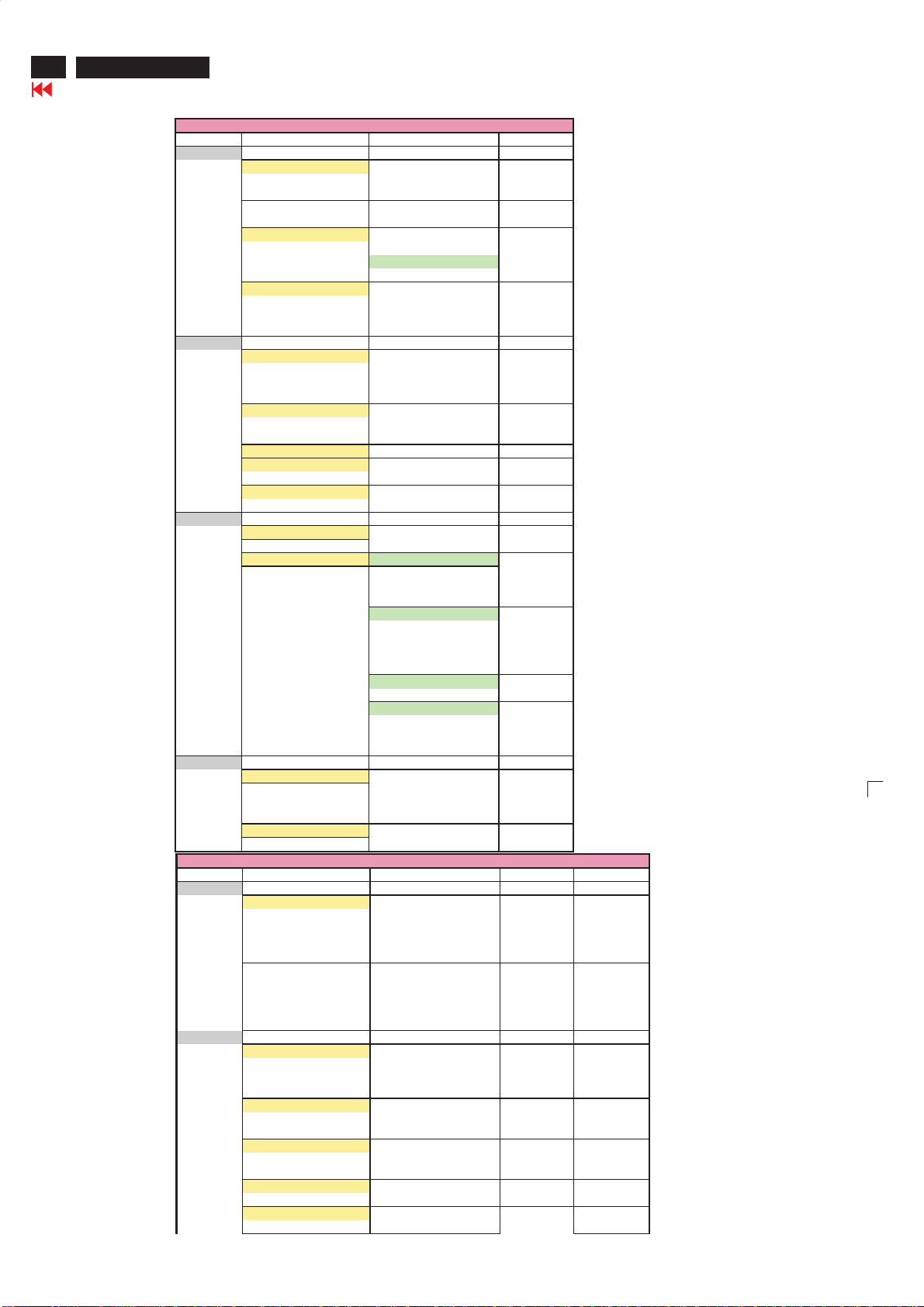
On Screen Display
1st Layer 2nd Layer 3rd Layer
PICTURE
COLOR TEMP NORMAL
BRIGHTNESS
CONTRAST
AUTO ADJUST YES
MANUAL ADJUST PHASE
AUDIO
AUTO SOUND PERSONAL
SETTINGS TREBLE
STEREO
INCREDIBLESURROUND INCREDIBLE SURROUND
AVL OFF
FEATURES
PICTURE FORMAT FULLSCREEN
PIP SIZE OFF
INSTALL
LANGUAGE ENGLISH
FACTORY RESET NO
TV /AV/ S-VIDEO/ HDTV MODE
1st Layer 2nd Layer 3rd Layer 4th Layer 5th Layer
PICTURE
AUTO PICTURE PERSONAL
BRIGHTNESS
COLOR
CONTRAST
SHARPNESS
TINT
AUDIO
AUTO SOUND PERSONAL
SETTINGS TREBLE
STEREO STEREO
INCREDIBLESURROUND OFF
AVL OFF
PC MODE
COOL
WARM
IN PROGRESS
STORE? YES
NO
CLOCK
HORIZONTAL
VERTICAL
VOICE
MUSIC
THEATRE
BASS
BALANCE
OFF
ON
4:3
SMALL
LARGE
PBP
VIDEO TV
AV1
AV2
S-VIDEO
COMPONENT
AUDIO PC
PIP
DISPLAY ICON1
ICON2
ICON3
ICON4
FRANÇAIS
ESPAÑOL
PORTUGUÊS
YES
RICH
NATURAL
SOFT
MULTIMEDIA
VOICE
MUSIC
THEATRE
BASS
BALANCE
SAP
MONO
INCREDIBLESURROUND
ON
Page 29

FEATURES
INSTALL
On Screen Display
PICTURE FORMAT WIDESCREEN (4:3)
4:3 (HD 4:3)
ZOOM 14:9
ZOOM 16:9
SUBTITLE ZOOM
SUPER WIDE
PICTURE ALIGNMENT
AUTO LOCK LOCK PROGRAM
CHANGE CODE YES
CLEAR ALL ON
OFF
BLOCK OPTION ON
OFF
MOVIE RATING G ON/OFF
PG ON/OFF
PG13 ON/OFF
R ON/OFF
NC17 ON/OFF
X ON/OFF
TV RATING Y ON/OFF
Y7 BLOCK ON/OFF
G ON/OFF
PG BLOCK ON/OFF
14 BLOCK ON/OFF
MA BLOCK ON/OFF
CLOSED CAPTION CAPTION MODE CC1
CC2
CC3
CC4
TXT1
TXT2
TXT3
TXT4
CC MUTE
CC DISPLAY ON
OFF
COLOR TEMP NORMAL
COOL
WARM
LANGUAGE ENGLISH
FRANÇAIS
ESPAÑOL
PORTUGUÊS
TUNER MODE
ATENNA
CABLE
ME5P 23"
Go to cover page
FV ON/OFF
V ON/OFF
S ON/OFF
L ON/OFF
D ON/OFF
V ON/OFF
S ON/OFF
L ON/OFF
D ON/OFF
V ON/OFF
S ON/OFF
L ON/OFF
29
Page 30

30
Go to cover page
Access Aging.. Mode
Step1:Select the source"PC" and then turnoff LCD-TV, and disconnect
Interface Cable between Monitorand PC.
Step 2 :[Push "power " button and then push the"VOL- " and "VOL+"
buttonsatthe same timeimmediately and holdit] untill comes out
"AGING screen" then release all buttons.
Bring up:
ME5P 23"
ATTENTION
ATTENTION
NO VIDEOINPUT
NO
VIDEO INPUT
AGING...
Aging Mode
After 55 seconds, bring up:
After 5 seconds, bring up:
After 55 seconds, bring up:
AGING...
----------
---------repeatly
Connect Signal cable again=> go back tonormal display
Page 31

Warning Message
CANNOT DISPLAY THIS VIDEO MODE, CHANGE
COMPUTER DISPLAY INPUT TO 1024 X 768 @ 60 Hz
NO VIDEO INPUT
OSDMAINMENULOCKED
OSD MAIN MENU UNLOCKED
""
ME5P 23"
Go to cover page
31
Page 32

32
ME5P 23"
Factory Mode
Go to cover page
Access factory. Mode
how to get into factory mode menu
Step1:Select the source "PC"andthen turn off LCD-TV.
Step 2 :[Push "power " button andthen push the"VOL- "and"VOL+"
buttons at the sametime immediatelyand hold i
then releaseall buttons.
Press "menu"button and bring up factory mode indication asshown in
Fig.1
t] about five seconds
MAIN CONTROLS
PICTURE
1024X768
SMART PICTURE
@60HZ
@60HZ
AUDIO BRIGHTNESS
FEATURES CONTRAST
INSTALL AUTO ADJUST
MANUAL ADJUST
ME5P NAFTA23 V0.12.6 050610C Qd123 QD23HL02
Fig.1
Usethe CHNNEL- and CHNNEL+ to select the"ME5PNAFTA20
V0.45.1 050527AU20SVGA"andthenpress t
he"VOL +" button
Menu ItemDescription
Scalar GainRGB Scalar Gain for Normal/Warm/CoolinPCmode.
Auto-Color
ADC Offset RGB Adjust AD 9883 for PC ADC offset.
ADC GainRGB Adjust AD 9883for PCADCgain.
PCOffset RGB PC analogscalar offset.
711X SDTV Brightness Adjust SA 7119 SDTV brightness.
Adjustcolor from received signal (either in PC or
HDTV mode).
131
711X SDTV SAT.
711X SDTV Contrast Adjust SA 7119 SDTV contrast.
711X SDTV TINT Adjust SA 7119 SDTV tint(hue).
TV Shift HV Adjust TV screenpositionhorizontally/vertically.
HD Shift HV
ShowLock Message Show OSD lock message.
HDTV ADC Offset RGB Adjust AD 9883 for HDTV ADC offset.
HDTV ADC GainRGB Adjust AD 9883 for HDTV ADC gain.
Video Scalar GainRGB Adjust scalar gain for Video mode.
Scalar Hue Adjust scalar hue.
Adjust SA 7119 SDTV saturation.
Adjust HDTV screenposition
horizon tally/vertically.
Page 33

Trouble shooting
No Power
.Check the TV power cord. Disconnect the power cord from the
power outlet for 10 seconds, then reinsert the plug into the outlet.
Press POWER to turn on the TV again.
.Make sure the outlet is not on a wall switch.
.Make sure a fuse has not blown at the power outlet.
No Pi cture
.Check the antenna or Cable TV connections. Connect the antenna or
Cable TV signal securely to the TV’s 75ohm jack on the rear of the TV.
.Set TUNER MODE correctly. Details are on page 15.
.Activate AUTO PROGRAM to find all available channels.
In case you hear only sound and don’t see any picture in S-Video or
Video (CVBS) mode. Please check if you have connected Video signal
to S-Video or Video (CVBS) input. Only one of the two video inputs can
be connected to sound. This means that the same sound can be heared
in S-Video and Video (CVBS) mode.
No Sound
.Press the VOL+ and VOL- buttons to adjust the volume.
.Press the MUTE button on the remote control to cancel or restore the
volume.
.If you have connected other equipment to the TV (such as a VCR or
DVD Player), make sure the audio cables are connected securely
between the TV and the other equipment.
.Check the SOUND settings.
.In case you hear wrong sound in S-Video or Video (CVBS) mode.
Please check if you have connected the right sound signal to AV in
(S-Video or Video input). Only one of the two video inputs can be
connected to sound, but both video signals can be connected.
This means that only one of the two sound inputs can be heared in
S-Video and Video (CVBS) mode.
Remote Control does not work.
.Check the batteries. If necessary, replace them with two AAA heavy
duty (zinc chloride) or alkaline batteries.
.Clean the remote control as well as the remote control sensor on the
front of the TV.
.Check the TV power cord. Disconnect the power cord from the power
outlet for 10 seconds, then reinsert the plug into the outlet. Press POWER
to turn on the TV again.
.Make sure the outlet is not on a wall switch.
.Make sure a fuse has not blown at the power outlet.
.Always point the remote control toward the front of the TV (toward the
remote sensor).
.Make sure that you use the supplied Magnavox Remote control, only the
supplied Magnavox Remote control can be used with this LCD-TV set.
TV displays wrong channel or no channels.
.Repeat channel selection.
.Add the channel number(s) into the TV’s memory. Use STORE.
.Make sure TUNER MODE is set correctly.
Then activate AUTO PROGRAM to set up all available channels.
ME5P 23"
Go to cover page
33
Page 34

34
ME5P 23"
Failure Mode Of Panel
Go to cover page
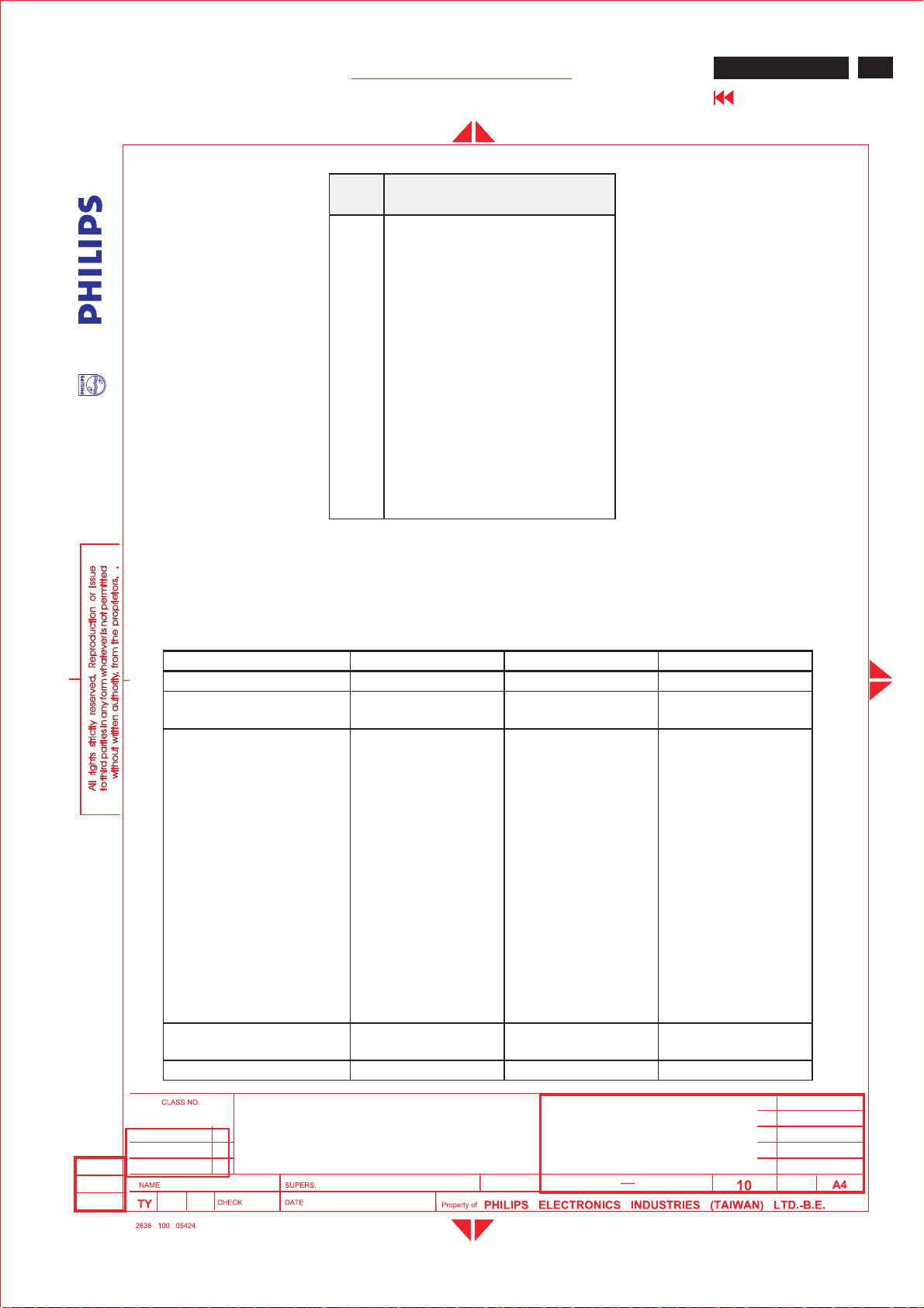
Quick reference for failure mode of LCD panel
this page presents problems that could be made by LCD panel.
It is not necessary to repair circuit board. Simply follow the mechanical
instruction on this manual to eliminate failure by replace LCD panel.
Polarizer has bubbles
Failure description
Vertical block defect
Vertical dim lines
Vertical lines defect
(Always bright or dark)
Horizontal block defect
Phenomenon
Polarizer has bubbles
Foreign material inside
polarizer. It shows liner or
dot shape.
Concentric circle formed
Horizontal dim lines
Horizontal lines defect
(Always bright or dark)
Has bright or dark pixel
Bottom back light of LCD is
brighter than normal
Back light un-uniformity
Backlight has foreign material.
Black or white color, liner or
circular type
Page 35

Wiring diagram
ME5P 23"
Go to cover page
35
Page 36

36
ME5P 15" & 20"
Go to cover page
Mechanical Instructions
Front View
Back View
Fig.1
4. Remove the metal frame board
- Remove the screws as shown in Fig.6-8
- Remove the metal frame board as Fig.9
Fig.5
1. Remove the base & back cover
- Remove the three screws 1,2,3 as shown in Fig.3,
then remove the base.
- Remove the other screws as shown in Fig.3 and Fig.4,
then remove the back cover
Fig.6
Fig.2
Fig.7
Fig.3
Fig.8
Fig.4
Fig.9
Page 37

5. Remove all PCB
- Remove all screws as shown in Fig.10
- Remove all PCB as shown in Fig.11
Mechanical Instructions
6. Remove the speakers and the panel from the bezel
- Remove the screws as shown in Fig.12
- Remove the speakers from the bezel
- Remove the panel from the bezel
Fig.10
ME5P 23"
Go to cover page
37
Fig.11
Fig.12
Page 38

38
.
ME5P 23"
Go to cover page
Electrical Instructions
1. General points
1.1 During the test and measuring, supply a distortion free AC
mains voltageto the apparatus via an isolated transformer with low
internal resistance.
1.2 All measurements mentioned her eafter are carried out at a
normal mains voltage (90 - 132 VAC for NAFTA v ersion, 195 -264 VAC
for EUROPEAN AP v ersion, or 90 - 264 VAC for the model with full
range power supply, unless otherwise stated.)
1.3 All voltages are to be measurement or applied with respect
to ground, unless otherwise stated.
1.4 The test has to be done on a complete set including LCD
panel in a room with temperature of 25 +/- 5 degree C.
1.5 All values mentioned in these test instruction are only
applicable of a well aligned apparatus, with correct signal.
1.6 The letters symbols (B) and (S) placed behind the test
instruction denotes
(B): carried out 100% inspection at assembly line
(S): carried out test by sampling
1.7 The white balance (color temperature), has to be tested in
subdued lighted room.
1.8 Repetitive power on/off cycle are allowed except it should be
avoided within 6 s ec.
2. Input and output signal
2.1.1 PC Signal type
Analog Video : 15 pin D-sub ,0.7 Vp-p linear, positive polarity
Separate Sync. : TTL level, separate, positive or negative polarity
Audio signal : 3.5mm stereo mini-jack
Level: Nominal : 0.5 V rms.
-Maximum :1.5Vrms.
-Impedance > 10 kohm
Signal source: pattern generator format as attachment
(table 1 to 5 ) Reference generator : CHROMA 2200 or 2250
2.1.2 TV Signal type
RF Signal : Aerial input / 10mV(80dBuV)
Video signal : Video( RCA jack, CVBS input) / 1Vpp (300mV-sync,
700mV-video.)
S video input / 1VppY-signal, 300mVpp C-signal
COMP Video( RCA jack , YPbPr input) / 1Vpp,Y signal ,
350mVpp Pb , Pr signal
DVI : Digital interface with 4 channels TMDS signal
Audio signal : Audio (1) R/L( RC A jack ) for AV IN1 ( share with Video and
S-video1 ).
Level: - Nominal : 0.5 V rms.
-Maximum :1.5Vrms.
- Impedance > 10 kohm
Audio (2) R/L ( RCA jack )for AV IN2 (share with Video2 and Comp video)
Level: - Nominal : 0.5 V rms.
-Maximum :1.5Vrms.
- Impedance > 10 kohm
Audio (3) R/L( RCA jack ) for DVI IN.
Level: - Nominal : 0.5 V rms.
- Maximum : 1.5 V rms.
- Impedance > 10 kohm
2.1.3 PVR output (CVBS output):
Video: CVBS output 1Vpp / Impedance : 75ohm
Audio: R/L output (from CVBS)
Level: - Nominal : 0.5 V rms.
-Maximum :1.5Vrms.
- Impedance < 1 kohm
2.2 PC Input signal mode
2.2.1 PRESET VIDEO RESOLUTION
The analogue color LCD monitor must be capable of displaying standard
resolutions within the vertical frequency range of 58 - 63 Hz, and
horizontal scan range of 30 - 50 KHz . Use the CHROMA-2250 generator
as the standard signal timing source.
Dot rate (MHz) H.freq
Mode Resolution V.freq (Hz) Remark
(KHz)
1 25.175 31.469 IBM
640 * 480 59.940
VGA
2 36.000 35.156 VESA 800 * 600 56.250
3 40.000 37.879 VESA 800 * 600 60.317
4 65.000 48.363 VESA 1024 * 768 60.004
5 74.500 44.772 WXGA 1280 * 720 59.855 CVT
5 79.500 47.776 WXGA 1280 * 768 59.87 CVT
Resolution recommend on 1280 X 768 @ 60Hz
2.3 TV input signal Channel and pattern for NAFTA model (Table1)
Signal Distrib uti on Table (NTSC)
TV
System
Pattern
CH
Frequency Carriers
Vid eo Sound
A03 61.25MHz 65.75MHz NTSC M Color Circle
A06 83.25MHz 87.75MHz NTSC M Red Raster
A09187.25MHz 191.75MHz NTSC M Circle Pattern
A11199.25MHz 203.75MHz NTSC M Cross Hatch
A13211.25MHz 215.75MHz NTSC M
Two White
Window
A52699.25MHz 703.75MHz NTSC M Color Bar
A69801.25MHz 805.75MHz NTSC M 100% White
C70499.25MHz 503.75MHz NTSC M Checkerboard
Tab l e 1
2.4 HD input mode
2.4.1 HDdetailtiming
(For Quantune Data setting with Q801GD or 802G in YpbPr mode)
Item 1920X1080i
Pixel rate 74.25MHz
Horizontal
Frequency
Active 1920 pixels
Blank 280 pixels
Period 2200 pixels
Pulse
delay
Pulse
width
Vertical
Frequency
Active 1080 lines
Blank 45 lines
Period 1125 lines
Pulse
delay
Pulse
width
EQ before 0 line 0 line 0 line 0 line
EQ after 1 line 0 line 1 line 0 line
Scan Interlace Progressive Interlace Progressive
Sync type ACS ACS ACS ACS
Video kind Analog YPbPr
60Hz
(13.468 ns)
33.75KHz 45KHz 28.125KHz 37.5KHz
(25.859 us)
(3.771 us)
(29.630 us)
44 pixels
(0.593 us)
44 pixels
(0.593 us)
60 Hz 60 Hz 50 Hz 50 Hz
(32.000 ms)
(1.333 ms)
(33.333 ms)
2 lines
(0.059 ms)
5 lines
(0.148 ms)
(ITU-R BT.709)
1280X720P
60Hz
74.25MHz
(13.468 ns)
1280 pixels
(17.239 us)
370 pixels
(4.983 us)
1650 pixels
(22.222 us)
70 pixels
(0.943 us)
40 pixels
(0.539 us)
720 lines
(16.0 ms)
30 lines
(0.667 ms)
750 lines
(16.667 ms)
5 lines
(0.111 ms )
5 lines
(0.111 ms)
Analog YPbPr
(ITU-R BT.709)
1920X1080i
50Hz
74.25MHz (
13.468ns )
1920 pixels
(25.859 us)
720 pixels
( 9.697 us )
2640 pixels
( 35.556 us )
484 pixels
( 6.519 us )
44 pixels
( 0.593 us )
1080 lines
( 38.4 ms )
45 lines
(1.6 ms )
1125 lines
(40ms)
2 lines
( 0.071 ms )
5 lines
(0.178 ms )
Analog YPbPr
(ITU-R BT.709 )
1280X720P
50Hz
74.25MHz
(13.468 ns)
1280 pixels
(17.239 us)
700 pixels
(9.428 us)
1980 pixels
(26.667 us)
400 pixels
(5.387 us)
40 pixels
(0.539 us)
720 lines
(19.2 ms)
30 lines
(0.8 ms)
750 lines
(20 ms)
5 lines
(0.133 ms )
5 lines
(0.133 ms)
Analog YPbPr
(ITU-R BT.709)
Page 39

Electrical Instructions
ME5P 23"
Go to cover page
39
Item 720X576P
Pixel rate 27 MHz
Horizontal
Frequency
Active 720 pixels
Blank 144 pixels
Period 864 pixels
Pulse
delay
Pulse
width
Vertical
Frequency
Active 576 lines
Blank 49 lines
Period 625 lines
Pulse
delay
Pulse
width
EQ before 0 line 0 line 2 line 3 line
EQ after 0 line 0 line 2 line 3 line
Scan Progressive Progressive Interlace Interlace
Sync type ACS ACS ACS ACS
Video kind Analog YPbPr
50Hz
(37.037 ns)
31.25 KHz 31.5KHz 15.625KHz 15.734KHz
(26.667 us)
(5.333 us)
(32.000 us)
12 pixels
(0.444 us)
64 pixels
(2.370 us)
50 Hz 60 Hz 50 Hz 59.94 Hz
(18.432 ms)
(1.568 ms )
(20.000 ms)
5 lines
(0.160 ms)
5 lines
(0.160 ms)
(SMPTE
RP177)
3. Power supply
720X480P
60Hz
27.027MHz
(37.000 ns)
720 pixels
(26.640 us)
138 pixels
(5.106 us)
858 pixels
(31.746 us)
16 pixels
(0.592 us)
62 pixels
(2.294 us)
480 lines
(15.238 ms)
45 lines
(1.429 ms)
525 lines
(16.667 ms)
9 lines
(0.287 ms)
6 lines
(0.190 ms)
Analog YPbPr
(SMPTE
RP177)
Table 2
720X576i
50Hz
13.5MHz
( 74.074 ns )
720 pixels
(53.333 us)
144 pixels
( 10.667 us )
864 pixels
( 64.00 us )
12 pixels
( 0.889 us )
63 pixels
( 4.667 us )
576 lines
( 36.864 ms )
49 lines
(3.136 ms )
625 lines
(40ms)
2 lines
( 0.128 ms )
3 lines
(0.192 ms )
Analog YPbPr
(SMPTE RP177 )
720X480i
60Hz
13.5MHz
( 74.074 ns )
720 pixels
(53.333 us)
138 pixels
( 10.222 us )
.
858 pixels
( 63.556 us )
19 pixels
( 1.407 us )
62 pixels
( 4.593 us )
480 lines
( 30.507 ms )
45 lines
(2.860 ms )
525 lines
( 33.367 ms )
4 lines
(0.254ms)
3 lines
(0.191 ms )
Analog YPbPr
(SMPTE
RP177 )
3.1 Setup the AC I/P at 264 VAC and 90VAC , and power board
provide two DC O utput
1. The DC output voltage is 24V +/- 1V DC for Inverter and Scaler
board
Measured point between pin3(+24V) and pin6(GND) at item 1001 of
scaler board
2. The DC output voltage is 16V+/- 1 V DC for Scaler and Audio board
Measured point between pin1(+16V) and pin6(GND) at item 1001 of
scaler board
3.2 Any adjustment is not needed.
4. TV Mode display adjust
The adjustment process must be primary with TV mode
4.1 White balance adjustment (B)
4.1.1 General set-up :
Equipment Requirements: Color analyzer.
Input requirements:
Input Signal Type : RF signal
1. Set to N TSC system, frequency=187.25MHZ
( for NAFTAmodel ) with white pattern of 100%
2. Select smart picture to PERSONAL MODE and
check the x, y data.
Input Signal Strength : 10mV (80 dBuV) terminal voltage.
Alignment method:
Initial Set-up :
1. Set TV(7119) Brightness=134; Saturate =58, C ontrast =64, Tint=24
2. Set Smart picture as “Personal”( Brightness=56; Saturate =62,
3. Apply “100% Full White” pattern by TV pattern gener ator.
1. Keep Gain R of video SCALER GAIN equals to 131
2. Adjust the VIDEO SCALER GAIN RG B
Input Injection Point : TV Tuner input
in Factory mode
Contrast =68, Sharpness=50,Tint=50
Alignment :
in Factory Mode
“N O R M A L ”. ( S e e F i g 1 . )
[ Enter factory menu : pr ess VOL+ and VOL- keys together around
six seconds]
Table 3: Reading with Minolta CA-110.
2. Check Gain R of video SCALER G AIN, It shall be R=131
3. Check the gray pattern should be distinguis h and color bar is correct
4.1.2 Set TV Color temperature in Factory mode as “WARM”, and
“COOL”
The VIDEO SCALER GAIN R\G\B v alue will be followed below
Normal WARM COOL
R gain 131 131 131
Ggain G G-4 G+1
B gain B B-10 B+12
FACTORY ADJUSTMENU
ORIGINAL PANNEL COLOR
SCALERGAIN R G B
AUTO-COLOR (OK)
ADC OFFSET R G B
ADC GAIN R G B
PC OFFSET R G B
7119 SDTV ? SAT TINT
DVI SHIFT H V
TV SHIFT H V
HD SHIFT H V
SHOW LOCKMESSAGE
HDTV ADC OFFSET R G B
HDTV ADC GAIN R G B
VIDEO SCALERGAIN R G B
SCALER HUE
Value
EXIT
5. PC mode Display Adjustment
5.1 Display quality adjustment
Usetimingmodeasdescribein2.2,andusethePOPO(pixelon
pixel off) pattern to adjust the clock until no stripe and adjust the
phase until clear picture.Check all pr e-set 6 modes.
5.2 WHITE-D adjustment (B)
5.2.1 At factory mode apply 1280X768 @60Hz mode with 32 gray
pattern. Set smart picture at “Normal”, and Brightness to 90% and
Contrast to 50%.Press AUTO-COLOR function for auto ADC offset
and gain setup.
5.2.2 Adjustment
1. Apply a 1280*768 / 60Hz signal with full white pattern, set
brightness control at 90%, and contrast control at 50%.
2. Keep Gain R of scaler gain R G B equals to 131,then
adjusting scaler gain R G B.
3. Check (X, Y) co-ordinates as below:
Nor mal/ (8500° K)
x (center) 0.292 ± 0.020
y (center) 0.293 ± 0.020
Table 4: Reading with Minolta CA-110.
4. Check Gain R of video SCALER GAIN, It shall be R=131
5. Check the gray level color poor & noise condition and chromaticity
Note: 1. Use Minolta CA-110 for color coordinates and luminance check.
2. Luminance> 400 cd/m
2
in the center of the screen at
(NORAML)color and PC Brightness control; Contrast control at 100%
5.2.3 Set S mart picture as “WARM, and “COOL”
TheSCALERGAINR\G\B valuewillbefollowedbelow
1. Check (X, Y) co-ordinates as below:
Nor mal/ (8500°K)
x (center) 0.292 ± 0.015
y (center) 0.293 ± 0.015
Normal WARM COOL
R gain 131 131 131
Ggain G-3 G-7 G-3
B gain B-5 B-16 B+9
Page 40

40
.
ME5P 23"
Go to cover page
Electrical Instructions
5.3 Check the digital interface cable (B)
Check the 64 gray level color poor & noise condition.
6. HDTV Mode display adjust
6.1 White balance adjustment (B)
General set-up:
Equipment : Quantum D ata Pattern Generator 801GD or 802G.
Apply 1080i, RGBW(177=Infocus2) gray pattern.
Or FLUKE 54200, apply 576i, DIGITAL SCAN/DIGI_ADC1 pattern.
7.2 DVI Video HDCP Key Test
7.2.1 Use pattern generator
Equipment: Quantum 802R or 802BT or equivalent equipments.
Pattern : Standard HDCP Pattern (It’s color bar)
Timing : 720 X 480P 60Hz
720 X 576P 50Hz
1280X 720P 50Hz
1280X 720P 60Hz
1920X1080i 50Hz
1920X1080i 60H
Result : The PASS information should be shown on the screen.
7.2.2 Use DVD Player:
Equipment: 1.Pioneer (model: DV-S969AVi) or equivalent equipments
2.DVD disk with ” Macro Vision “ protection.
Result : The picture should be shown Normally.
8. Preset EEPROM data
EEPROM data has to be preset data according following table.
8.1 Fact or y m od e pr eset .
Function
SCALER GAIN
ADC Offset R/G/B
ADC Gain R/G/B
PC OFFset R/G/B
7119 ? b ri gh tn ess
7119 Saturation
7119 contrast
7119 TINT
DVI SHIFT H
DVI SHIFT V
Pres et v alu e
131 127 127
127 127 127
127 127 127
127 127 127
#1
#1
#1
#1
#2 #2
#2 #2
NTSC PAL-N
Alignment method:
Initial S et-up : 1.Set Smart picture as “Personal”(Brightness=56,
Color=62, Contrast=68, Sharpness=50, Tint=50 for ONLY Factory
Alignment )
2.Press AUTO-COLOR process.
Alignments :
1.Set HD VIDEO SCALER GAIN R\G\B = the fol lowi ng table
For Nornal,Cool and Warm color temperature.
Note:The G1 and B1 are TV’s VIDEO SCALER GAIN G\B
Norm al. WARM COOL
R gain 131 131 131
Ggain G G-5 G+1
Bgain B+3 B-8 B+14
2. Apply “100% Full White” pattern by Quantum DATA 802G pattern
generator.
Check (X, Y) co-ordinates as below:
Nor mal/ (8500°K)
x (center) 0.292 ± 0.020
y (center) 0.293 ± 0.020
If chromaticity (X, Y) co-ordinates is out of specification, realignment Video scalar R/G/B gain from 131/127/127.
2. Check the gray pattern should be distinguish and color bar is
correct
7. Preset DVI HDCP Key
7.1 Download HDCP Key
The 284 bytes HDCP key should be download to the TV set via IF
cable using ATE at factory Alignment tools
TV shift H
TV shift V
HD SHIFT H
HD SHIFT V
HD ADC OFFset R G B
HD ADC GAIN R G B
Video Scaler Gain
Scaler Hue
Regu lar
175 186
15 0
#3 #3
#3 #3
127 127 127
127 127 127
131 127 127
50
#1
PERSONAL/
NORMAL
TV
AV
S-Video
Com ponen t
?SAT.
TINT
127586424
127586424
134646424
1347062 --
#2
480P576P720P
/50Hz
720P
/60Hz
1080i
/50Hz
DVI shift H 22 22 96 55 103 48
DVIshiftV445040406060
#3
480i 480P 576i 576P 720P
HD
155 154 167 167 108 107 79 79
shift H
HD
39 40 49 53 39 39 58 58
shift V
/50Hz
720P
/60Hz
1080i
/50Hz
1080i
/60Hz
1080i
/60Hz
Page 41

Electrical Instructions
ME5P 23"
Go to cover page
41
8.2 Smart picture setting
RF PERSONAL RICH NATURE SOFT MULTIMEDIA
Brightness 56 63 47 42 61
Col or 62 58 52 50 67
Con tr ast 68 72 68 52 78
Sharpnes s 50 66 58 66 66
Tint 50 50 50 50 50
AV1/AV2/S-
video
PERSONAL RICH NA TURE SOFT MULTIMEDIA
Brightness 56 63 50 40 57
Col or 62 60 52 50 70
Con tr ast 68 72 67 52 78
Sharpnes s 87 87 75 62 79
Tint 50 50 50 50 50
HD/
Com ponen t PERSONAL RICH NATURE SOFT MULTIMEDIA
Brightness 56 56 50 43 56
Col or 64 64 60 60 75
Con tr ast 68 68 58 50 75
Sharpnes s 59 59 59 59 59
Tint 50 50 50 50 50
Smart
Region Model Volum e
NAFTA /
LATAM
23PF5320/28 50 Theater Ri ch
20PF5120/28 50 Theater Ri ch
15PF5120/28 50 Theater Ri ch
CHINA 23PF5320/93 50 Theater Rich Channel 1
20TA1000/93 50 Theater Ri ch Channel 1 4:3 N
15TA1000/93 50 Theater Ri ch Channel 1 4:3 N
23PF5320/79,
AP
/98
20TA1000/79,
/98
15TA1000/79,
/98 50 Theater Ric h Channel 1 4:3 N
Sound
50 Theater Ri ch Channel 1
50 Theater Ri ch Channel 1 4:3 N
Smart
Pict ure
RF Chan nel Fo rmat
Channel 2
(Auto)
Channel 2
(Auto) 4:3 N
Channel 2
(Auto)
Virg in
Mode
Inst allati on
Wide
Screen
4:3 N
Wide
Screen N
Wide
Screen
N
N
DVI PERSONAL RICH NATURE SOFT MULTIMEDIA
Brightness 56 56 47 40 56
Col or 64 75 70 70 85
Con tr ast 68 58 48 40 65
Sharpnes s 50 63 61 59 79
Tint 50 50 50 50 50
8.3 Smart sound setting
Smart Sound : Personal
SOUND VOLUME : 50
BASE : 50
TREBLE : 50
Balance : 0
Virtuel SURROUND : OFF
AVL : OFF
All Source Input Voice Theater Music Personal
EQ Band1 120Hz
EQ Band2 500Hz
EQ Band3 1.5KHz
EQ Band4 5KHz
EQ Band5 10KHz
-19 +25 +16 0
+25 +40 +30 0
+57 +10 -10 0
+17 +54 +56 0
+14 +56 +50 0
8 .4 Out of Box Setting (B)
The OSD Controls shall have the following factory default
values after finishing all the adjustment.
1. Volume= 50
2. Smart Sound = Theater
3. Smart Picture = RICH
4. RF Channel = Channel 2
5. Tuner Mode = Auto
6. Format = Wide Screen
7. incredible surround = off
8. AVL = off
9. color temp = Normal
10. language = English
Page 42

42
ME5P 23"
Display adjustment
Go to cover page
Display adjustment
Access factory.Mode
how toget intofactorymode menu
Step 1:Selectthesource "PC" and then turn off LCD-TV.
Step 2 :[Push"power"button and then push the "VOL- " and "VOL+"
buttons at the same time immediately and hold it] about fiveseconds
then release all buttons.
Fig.3
Press "menu"button and br
Fig.1
MAIN CONTROLS
PICTURE
ing up factorymode indicationasshownin
@60HZ
1024X768
@60HZ
SMART PICTURE
AUDIO BRIGHTNESS
FEATURES CONTRAST
INSTALL AUTO ADJUST
MANUAL ADJUST
ME5P NAFTA23V0.12.6 050610C Qd123QD23HL02
Fig. 1
Use the CHNNEL- and CHNNEL+ to selectthe "F1/FL1 NAFTA V1.01.
05 041208 LG15XGA" and then press the "VOL +" button
2.Apply a 1024x768/60Hzsignal withwhite pattern.Set
brightness controlat50% and contrast controlat50%.Adjust the
R.G.B gain toreach special color temperature on centerof
screen.
2.1 Aim theprobe CA-A30 at the centerofscreen as Fig. 4
2.2 Removethe lens protectiv
2.3 Set Measuring/viewing selector toMeasuring position for r eset
analyzer. (Zero calibration) as Fig. 5
2.4 Turn onthe colour analyzer (CA-110).
2.5 Press 0-CAL buttonto start reset analyzer. S ee Fig. 6
e coverofprobe CA-A30.
Measurement viewing selector
Fig.4
Cover (black)
Fig.5
131
Fig.2
PC mode WHITE-D adjustment (B)
1Apply 1024X768/60Hzmode with5block patternasFig3.Set
main controls brightness controlat50% and contrast to50% on
User mode.Set color setting at natural color on User mode.Move
cursor to "AUTO-color" item on factorymode, press
to activethis function, then scalerwill adjust RGB and Color
RGB automatically by it self.
"menu" key
O-CAL
Fig.6
2.6 Switch lightprobetoViewing position.
2.7 Movethe Lens barrel forward or backwardtoget clear imageas
showninFig. 7
2.8 Switch lightprobetoMeasuring position.Itshould beable to
indicate colourvalue onthe CA-110.
Clear image
Measurement/viewing selector
Fig.7
Page 43

Display Adjustment
ME5P 23"
Go to cover page
43
2.9 Set smart picture as NORMAL
Set SCALER GAIN R G B
The 1931 CIE chromaticity (X, Y) co-ordinates shall be:
x (center) 0.292 ± 0.020
y (center) 0.293 ± 0.020
Readings with Minolta CA-110.
2.10 Set Smart picture as WARM , and COOL The SCALER GAIN R G B
.
R gain 131 131 131
G gain G-3 G -3 G -7
B gain B-5 B -16 B+9
"
= VIDEO SCALER GAIN R G B(alignment done).
Nor mal /
"
Nor mal / the R \G \B are
gain after alignment.
"
"
"
'
"
'
'
WARM COOL
=
Page 44

44
ME5P 23"
Go to cover page
Safety Test Requirements
All units that are returned for service or repair must pass the
original manufactures safety tests. Safety testing requires both
and testing.Hipot Ground Continuity
HI-POT TEST INSTRUCTION
1.Application requirements
1.1 All mains operated products must pass the Hi-Pot test as
described in this instruction.
1.2 This test must be performed again after the covers have
been refitted following the repair, inspection or modification
of the product.
Test method
2.
2.1 Connecting conditions
2.1.1 The test specified must be applied between the parallel-
blade plug of the mainscord and all accessible metal
parts of the product.
2.1.2 Before carrying out the test, reliable conductive
connections must be ensured and thereafter be
maintained throughout the test period.
2.1.3 The mains switch(es) must be in the "ON" position.
2.2 Test Requirements
All products should be HiPot and Ground Continuity tested as
follows:
3. Equipments and Connection
3.1. Equipments
For example :
- ChenHwa 9032 PROGRAMMABLE AUTO SAFETY
TESTER
- ChenHwa 510B Digital Grounding Continuity Tester
- ChenHwa 901 (AC Hi-pot test), 902 (AC, DC Hi-pot test)
Withstanding Tester
3.2. Connection
* Turn on the power switch of monitor before Hipot and
Ground Continuity testing.
Clip
Clip
Condition HiPot Test for HiPot Test for Ground Continuity
products where products where Test requirement
the mains input the mains input is
range is Full 110V AC(USA
range(or 220V type)
AC)
Test 2820VDC 1700VDC Test current:
voltage (2000VAC) (1200VAC) 25A,AC
Test time:
Test time 3 seconds 1 second 3 seconds(min.)
(min.) Resistance
required:
Trip set at 100 uA 5 mA <=0.09+Rohm,
current for Max. R is the
(Tester) limitation; set resistance of
at 0.1 uA for the mains cord.
Min. Limitation
Ramp set at 2
time seconds
(Tester)
2.2.1 The minimum test duration for Quality Control Inspector
must be 1 minute.
2.2.2 The test voltage must be maintained within the specified
voltage + 5%.
(ChenHwa 9032 tester)
Video cable
Connect the "video cable"
or "grounding screw"
to the CLIP on your tester.
Grounding screw
Connect the power cord
to the monitor.
2.2.3 There must be no breakdown during the test.
2.2.4 The grounding blade or pin of mains plug must be
conducted with accessible metal parts.
Power outlet
(Rear view of monitor)
Hipot and Ground Continuity testing records have to be kept
for a period of 10 years.
Page 45

Go to cover page
General
DDC Data Re-programming
In case the DDC data memory IC or main EEPROM which storage all
factory settings were replaced due to a defect, the serial numbers have
to be re-programmed" ".
It is advised to re-soldered DDC IC and main EEPROM from the old
board onto the new board if circuit board have been replaced, in this
case the DDC data does not need to be re-programmed.
Additional information
Additional information about DDC (Display Data Channel) may be
obtained from Video Electronics Standards Association (VESA). Extended
Display Identification Data(EDID) information may be also obtained from
VESA.
Analog DDC IC, & EEPROM
System and equipment requirements
1. An i486 (or above) personal computer or compatible.
2. Microsoft operation system Windows 95/98 .
Y o Install the EDID_PORT_Tool under Win2000/XP . As
ou have t
Fig. 1 .
Fig. 1Fig.
1
A. Copy the "UserPort.sys" to C:\WINNT\system32\drivers(win2000)
C:\WINDOWS\system32\drivers(winXP)
B. Running " io.exe" everytime, Before you start to programming
edid data .
3. EDID45.exe program .
4. DDC 2BI-ISP TOOL:
Inclusion :
A. DDC2BI-ISP TOOL(3138 106 10396) x1 (as Fig. 2)
B. Printer cable x1
c. (D-Sub) to (D-Sub) cable x2
D. D-SUB to DVI cable X1
Note: The EDID46.EXE is a windows-based program, which cannot
be run in MS-DOS.
To Printer port
Fig. 2Fig. 2
Pin Assignment
The digital only connector contains 24 signal contacts organized in
three rows of eight contacts. Signal pin assignments are listed in the
following table:
To Printer port
DC 8~12V
DC 8~12V
Power
Pin No. Description
indicator
Power
indicator
PIN No. SIGNAL
1Red
2Green
3Blue
4GND
5 Self test
6RedGND
7 Green GND
8BlueGND
9 +5V (Supply from PC)
10 Sync GND
11 GND
12 Bi-directional data
13 H-sync
14 V-sync
15 Data clock
To Monitor
D-sub/DVI cable
To Monitor
D-sub cable
1RX2-
2RX2+
3GND
4GND
5GND
6 DDC clock
7 DDC data
8GND
9RX1-
10 RX1+
11 GND
12 GND
13 GND
14 +5V
15 DVI-D self test
16 +5V
17 RX0-
18 RX0+
19 GND
20 GND
21 GND
22 GND
23 RXC+
24 RXC-
Fig. 3Fig. 3
Fig. 4Fig. 4
Page 46

Go to cover page
Configuration and procedure
There are 3 chips contained OSD string, serial number..etc
on the circuit board, main EEPROM which storage all factory settings,OSD
string. DDC IC which storage 128byte EDID data(serial number ..etc.).
Following descirptions are the connection and procedure for Analog
/Digital and main EEPROM can be re-programmed along with
Analog/Digital IC by enable factory memory data write function on the
DDC program (EDID45.EXE).
Initialize alignment box
In order to avoid that monitor entering power saving mode due
to sync will cut off by alignment box, it is necessary to initialize
alignment box before running programming software
(EDID45.EXE). Following steps show you the procedures and
connection.
Step 1: Supply 8-12V DC power source to the Alignment box by
plugging a DC power cord or using batteries.
Step 2: Connecting printer cable and D-Sub cable of monitor as Fig. 5
PC
1=Power connector
2=D-SUB/DVI connector
3. At the submenu, type the letter of your computer's hard disk drive
followed by :EDID45 (for example, C:\EDID45, as shown in Fig. 7).
Edid45.exe
Fig. 7
4. Click button. The main menu appears (as shown in Fig. 8).OK
This is for initialize alignment box.
DC Power
8-12 V
----->
1
To printer port (LTP1)
Printer
Port
To PC
To Monitor
----->
2
Fig. 5
Step 3: Installation of EDID45.EXE
Method 1: Start on DDC program
Start Microsoft Windows.
1. The Program"EDID45.EXE" in service manual cd-rom be copyed to C:\ .
2. Click , choose Run at start menu of Windows as shown
In Fig. 6.
Fig. 8
Note 1: If the connection is improper, you will see the following error
message (as shown in Fig. 9) before entering the main menu.
Meanwhile, the (read EDID) function will be disable. At this
time,
please make sure all cables are connected correctly and
Edid45.1
Fig. 9
1
Note 2: During the loading, EDID45 will verify the EDID data which just
loaded from monitor before proceed any further function, once
the data structure of EDID can not be recognized, the following
error message will appear on the screen as below. Please
confirm following steps to avoid this message.
1. The data structure of EDID was incorrect.
2. DDC IC that you are trying to load data is empty.
3. Wrong communication channel has set at configuration setup
Fig. 6
Fig. 10
Page 47

Go to cover page
Re-programming Analog DDC IC
Step 1: After initialize alignment box, connecting all cables and
box as shown in Fig. 11
1=Power connector
2=D-SUB connector
PC
To PC
To printer port (LTP1)
To Monitor
Printer
Port
Step 2: Read DDC data from monitor
1. Click icon as shown in Fig. 11 from the tool bar to bring up
the Channels "Configuration Setup" windows as shown in Fig. 12.
Fig. 11
Step 3: Modify DDC data (verify EDID version, week, year)
1. Click (new function) icon from the tool bar, bring up
Step 1 of 9 as shown in Fig. 15 .
EDID45 DDC application provides the function selection and
text change (select & fill out) from Step 1 to Step 9.
To Printer port
To Printer port
DC 8~12V
DC 8~12V
DC 8~12V
To Monitor
To Monitor
D-sub/DVI cable
To Monitor
D-sub/DVI cable
D-sub cable
Power
indicator
Power
indicator
Select and fill out,
If necessary.
Fig. 15
Step 4: Modify DDC data (Monitor Serial No.)
Next1. Click to step7, bring up Fig. 16.
- Serial number can be filled up or be changed at this moment.
- Click next,Finish to exit the Step window.
Fig. 12
2. Select the DDC2Bi as the communication channel.
As shown in Fig. 13.
Fig. 13
3. Click OK button to confirm your selection.
4. Click icon (Read EDID function) to read DDC EDID data from
monitor. The EDID codes will display on screen as shown in Fig. 14.
Fig. 16
To Printer port
Don't close this screen. --->
Fig. 14
Page 48

48
ME5P 23"
Go to cover page
DDC INSTRUCTIONS
Step 5: Write DDC data
1. Configuration should be as Fig. I. And press OK.
Fig. I
Access factory. Mode
Step1:Select the source "PC" and then turn off LCD-TV.
Step 2 :[Push "power " button and then push the "VOL- " and "VOL+"
buttons at the same time immediately and hold it] about five seconds
then release all buttons.
Press "menu"button and bring up factory mode indication
3. Click (Write EDID) icon from the tool bar to write DDC data.
Bring up "Writing 0%~100%, ready" a progressing bar on the left
down corner.
4. Turn off/on monitor
Step 7: Exit DDC program
Pull down the File menu and select Exit as shown in Fig. III.
Fig. III
Step 6: Save DDC data
Sometimes, you may need to save DDC data as a text file for using
in other IC chip. TosaveDDC data, follow the steps below:
1. Click (Save) icon (or click "file"-> "save as") from the tool bar
And give a file name as shown in Fig. II
The file type is EDID45 file (*.ddc) which can be open in WordPad.
By using WordPad, the texts of DDC data & table (128 bytes, hex
code) can be modified. If DDC TEXTS &HEX Table are completely
correct, it can be saved as .ddc flie to re-load it into DDC IC for DDC
Data application.
150S5-DDC
ME5P-DDC
C:\My documents\ME5P-DDC
45
Fig. II
2. Click .Save
Page 49

DDC Instructions
ME5P 23"
Go to cover page
49
Re-programming Digital DDC IC
Step 1: After initialize alignment box, connecting all cables and
box as shown in Fig. 17
1=DVI connector
2=D-SUB connector
3=Power Plug
3
To P C
To Monitor
Printer
Port
Fig.17
Step 2: Read DDC data from monitor
1. Click icon as shown in Fig. 18 from the tool bar to bring up
the Channels "Configuration Setup" windows as shown in Fig. 19.
Step 3: Modify DDC data (verify EDID version, week, year)
1. Click (new function) icon from the tool bar, bring up
Step 1 of 9 as shown in Fig. 21 .
EDID45 DDC application provides the function selection and
text change (select & fill out) from Step 1 to Step 9.
To Printer port
DC 8~12V
DC 8~12V
To Monitor
To Monitor
D-sub/DVI cable
D-sub/DVI cable
Select and fill out,
If necessary.
Fig. 21
Step 4: Modify DDC data (Monitor Serial No.)
Next1. Click , bring up Fig. 22. Then select Digital Signal as below
Fig. 18
2. Select the DDC2Bi as the communication channel.
As shown in Fig. 19.
Fig. 19
3. Click OK button to confirm your selection.
4. Click icon (Read EDID function) to read DDC EDID data from
monitor. The EDID codes will display on screen as shown in Fig. 20.
Fig. 22
2. Click to step7, bring up Fig. 23.Next
- Serial number can be filled up or be changed at this moment.
- Click Next, Finish to exit the Step window.
Fig. 20
Fig. 23
Page 50

50
ME5P 23"
Go to cover page
Step 5: Write DDC data
1. Configuration should be as Fig. 24. And press OK.
DDC Instructions
2.Access factory. Mode
Step 1 : Select the source "PC" and then turn off LCD-TV.
Step 2 :[Push "power " button and then push the "VOL- " and "VOL+"
buttons at the same time immediately and hold it] about five seconds
then release all buttons.
Press "menu"button and bring up factory mode indication
3. Click (Write EDID) icon from the tool bar to write DDC data.
Step 6: Save DDC data
Sometimes, you may need to save DDC data as a text file for using
in other IC chip. To save DDC data, follow the steps below:
1. Click (Save) icon (or click "file"-> "save as") from the tool bar
And give a file name as shown in Fig. 25.
The file type is EDID46 file (*.ddc) which can be open in WordPad.
By using WordPad, the texts of DDC data & table (128 bytes, hex
code) can be modified. If DDC TEXTS&HEX Table are completely
correct, it can be saved as .ddc flie to re-load it into DDC IC for DDC
Data application.
Fig. 24
Fig. 25
2.Click .Save
Step 7: Exit DDC program
Pull down the File menu and select Exit as shown in Fig. 26.
Edid45.1
Fig. 26
Page 51

DDC DATA
ME5P 23"
Go to cover page
51
For D-SUB
**********************************************************************
EDID log file (31052005_Me5P23_A_V1)
**********************************************************************
Vendor/Product Identification
EDID Version, Revision
BasicDisplayParameters/Features
Color Characteristics
Established Timings
Established Timings I : 640 x 480 @60Hz (IBM,VGA
Established Timings II : 1024 x 768 @60Hz (VESA)
Standard Timing Identification#1
ID Manufacturer Name :PHL
ID Product Code : 0000 (HEX.)
ID SerialNumber :1(DEC.)
Week ofManufacture :22
Year ofManufacture : 2005
sion:1
Ver
Revision:3
Video InputDefinition:Analog Video Input
ximum H Image Size :51
Ma
Maximum V Image Size :29
Display Transfer Characteristic :2.2
Feature Support (DPMS) : Standby
Display Type :RGB color display
Standard DefaultColor Space :Primary color space
Preferred
RedXcoordinate : 0.632
RedYcoordinate : 0.336
GreenXcoordinate : 0.264
GreenYcoordinate : 0.593
Blue X coordinate : 0.144
Blue Y coordinate : 0.058
White X coordinate : 0.292
White Y coordinate : 0.293
Manufacturer's timings:
Horizontal active pixels : 1280
Aspect Ratio : 16:9
Refresh Rate :60
(gamma)
Timing Mode : Detailed timing block1
800 x 600 @56Hz (VESA)
800 x 600 @60Hz (VESA)
0.700V/0.000V (0.70Vpp)
without Blank-to-BlackSetup
Separate Sync
Composite Sync
without Syncon Green
no Serration required
Suspend
noActive Off
)
:Positive VerticalSync.
:Negative HorizontalSync.
Monitor Descriptor #2
SerialNumber : 00001
Monitor Descriptor #3
Monitor Name : 23PF5320
Monitor Descriptor #4
Monitor Range Limits
Min. VtrateHz : 56
Max. VtrateHz : 63
Min. Horiz. rate kHz : 30
Max. Horiz. rate kHz : 50
ax. SupportedPixel:80
M
No secondary GTF timing formula supported.
ExtensionFlag :0
Check sum : 37 (HEX.)
**********************************************************************
EDID data (128 bytes)
**********************************************************************
0: 00 1: ff 2: ff 3: ff 4: ff 5: ff 6: ff 7: 00
8: 41 9: 0c 10: 00 11: 00 12: 01 13: 00 14: 00 15: 00
16: 16 17: 0f 18: 01 19: 03 20: 6c 21: 33 22: 1d 23: 78
24: ce 25: cb 26: fc 27: a1 28: 56 29: 43 30: 97 31: 24
32: 0e 33: 4a 34: 4b 35: 23 36: 08 37: 00 38: 81 39: c0
40: 01 41: 01 42: 01 43: 01 44: 01 45: 01 46: 01 47: 01
48: 01 49: 01 50: 01 51: 01 52: 01 53: 01 54: 0e 55: 1f
56: 00 57: 80 58: 51 59: 00 60: 1e 61: 30 62: 40 63: 80
64: 37 65: 00 66: 74 67: df 68: 10 69: 00 70: 00 71: 1c
72: 00 73: 00 74: 00 75: ff 76: 00 77: 30 78: 30 79: 30
80: 30 81: 31 82: 0a 83: 20 84: 20 85: 20 86: 20 87: 20
88: 20 89: 20 90: 00 91: 00 92: 00 93: fc 94: 00 95: 32
96: 33 97: 50 98: 46 99: 35 100: 33 101: 32 102: 30 103: 0a
104: 20 105: 20 106: 20 107: 20 108: 00 109: 00 110: 00 111: fd
112: 00 113: 38 114: 3f 115: 1e 116: 32 117: 08 118: 00 119: 0a
120: 20 121: 20 122: 20 123: 20 124: 20 125: 20 126: 00 127: 37
Detailed Timing #1
Pixel Clock (MHz) : 79.5
H Active (pixels) : 1280
HBlankin
V Active (lines) : 768
VBlanking (lines) : 30
HSync Offset (F Porch) (pixels): 64
HSync Pulse Width(pixels) : 128
VSync Offset (F Porch) (lines) : 3
VSync Pulse Width (lines) : 7
HImage Size (mm) : 372
VImage Size (mm) : 223
HBorder (pixels) : 0
VBorder (lines) : 0
Flags:Non-interlaced
g (pixels) : 384
:Normal D
: DigitalSeparate sync.
isplay, No stereo
Page 52

52
ME5P 23"
Go to cover page
For DVI-D
**********************************************************************
EDID log file (31052005_Me5P23_D_V1)
**********************************************************************
Vendor/Product Identification
EDID Version, Revision
Basic Display Parameters/Features
Color Characteristics
ID Manufacturer Name : PHL
ID Product Code : 0000 (HEX.)
ID Serial Number : Unused
Week of Manufacture : 22
Year of Manufacture : 2005
Version : 1
Revision : 3
Video Input Definition : Digital Video Input
Maximum H Image Size : 51
Maximum V Image Size : 29
Display Transfer Characteristic : 2.2
(gamma)
Feature Support (DPMS) : no Standby
no Suspend
no Active Off
Display Type : RGB color display
Standard Default Color Space : Primary color space
Red X coordinate : 0.632
Red Y coordinate : 0.336
Green X coordinate : 0.264
Green Y coordinate : 0.593
Blue X coordinate : 0.144
Blue Y coordinate : 0.058
White X coordinate : 0.292
White Y coordinate : 0.293
DDC DATA
: Positive Vertical Sync.
: Positive Horizontal Sync.
Detailed Timing #2
Pixel Clock (MHz) : 27
H Active (pixels) : 720
H Blanking (pixels) : 138
V Active (lines) : 480
V Blanking (lines) : 45
H Sync Offset (F Porch) (pixels): 16
H Sync Pulse Width (pixels) : 62
V Sync Offset (F Porch) (lines) : 9
V Sync Pulse Width (lines) : 6
H Image Size (mm) : 576
V Image Size (mm) : 324
H Border (pixels) : 0
V Border (lines) : 0
Flags : Non-interlaced
:NormalDisplay, No stereo
: Digital Separate sync.
: Negative Vertical Sync.
: Negative Horizontal Sync.
Monitor Descriptor #3
Monitor Name : 23PF5320
Monitor Descriptor #4
Monitor Range Limits
Min.VtrateHz : 47
Max. Vt rate Hz : 61
Min. Horiz. rate kHz : 30
Max. Horiz. rate kHz : 47
Max. Supported Pixel : 80
No secondary GTF timing formula supported.
Extension Flag : 0
Check sum : A3 (HEX.)
Established Timings
Standard Timing Identification : Unused
Detailed Timing #1
Established Timings I : 640 x 480 @60Hz (IBM,VGA)
Established Timings II :
Manufacturer's timings :
Pixel Clock (MHz) : 74.25
H Active (pixels) : 1920
H Blanking (pixels) : 280
V Active (lines) : 540
V Blanking (lines) : 22
H Sync Offset (F Porch) (pixels): 88
H Sync Pulse Width (pixels) : 44
V Sync Offset (F Porch) (lines) : 2
V Sync Pulse Width (lines) : 5
H Image Size (mm) : 576
V Image Size (mm) : 324
H Border (pixels) : 0
V Border (lines) : 0
Flags : Interlaced
:NormalDisplay, No stereo
Digital Separate sync.
:
**********************************************************************
EDID data (128 bytes)
**********************************************************************
0: 00 1: ff 2: ff 3: ff 4: ff 5: ff 6: ff 7: 00
8: 41 9: 0c 10: 00 11: 00 12: 01 13: 01 14: 01 15: 01
16: 16 17: 0f 18: 01 19: 03 20: 80 21: 33 22: 1d 23: 78
24: 0c 25: cb 26: fc 27: a1 28: 56 29: 43 30: 97 31: 24
32: 0e 33: 4a 34: 4b 35: 20 36: 00 37: 00 38: 01 39: 01
40: 01 41: 01 42: 01 43: 01 44: 01 45: 01 46: 01 47: 01
48: 01 49: 01 50: 01 51: 01 52: 01 53: 01 54: 01 55: 1d
56: 80 57: 18 58: 71 59: 1c 60: 16 61: 20 62: 58 63: 2c
64: 25 65: 00 66: 40 67: 44 68: 21 69: 00 70: 00 71: 9e
72: 8c 73: 0a 74: d0 75: 8a 76: 20 77: e0 78: 2d 79: 10
80: 10 81: 3e 82: 96 83: 00 84: 40 85: 44 86: 21 87: 00
88: 00 89: 18 90: 00 91: 00 92: 00 93: fc 94: 00 95: 32
96: 33 97: 50 98: 46 99: 35 100: 33 101: 32 102: 30 103: 0a
104: 20 105: 20 106: 20 107: 20 108: 00 109: 00 110: 00 111: fd
112: 00 113: 2f 114: 3d 115: 1e 116: 2f 117: 08 118: 00 119: 0a
120: 20 121: 20 122: 20 123: 20 124: 20 125: 20 126: 00 127: a3
Page 53

ISP INSTRUCTIONS
ME5P 23"
Go to cover page
53
Configuration and procedure
"Easywriter " The software
firmware of CPU.
It is a windows-based program, which cannot be run in MS-DOS.
DDC2BI_ISP TOOL (3138 106 10396)
"Parallel Port of PC" and "15 pin-D-SUB connector of Monitor".
is provided by Novatek to upgrade the
is for the interface between
System and equipment requirements
1. An i486 (or above) personal computer or compatible.
2. Microsoft operation system Windows 95/98/2000/XP.
3. ISP Software " Easywrite "
4. as shown in Fig. 1
DDC2BI_ISP TOOL (3138 106 10396)
Parallel Port to Print Port in PC
D-SUB to monitor
Fig. 1
5 Connect and Mains cord to Monitor as shown
. DDC2BI_ISP TOOL
in Fig. 2.
Fig. 4
Click the next till complete the setup
Step 5 :Copy the hex code to C:\ME5P as shown in Fig. 5 .
170S5
Fig. 5
Update the firmware
1. DoubleclicktheEasywriter.exeiconindesktopthenappears
window as shown in Fig.7 .
ME5P -Monitor (B)
D-Sub
Connect to Mains
cord at this moment.
6. Install and setup the Easywriter program
Step 1 : Make a folder in your PC as shown in Fig. 3.
Step 2 : Copy ISP Software Easywriter into your folder
Step 3 : Unzip Easywriter.zip into your folder as shown in Fig. 3.
Step 4 : Double click the EasywriterV2.09.exe icon to install the
------------------------------->
Fig.2
ISP box
For example : C:\ME5P
as shown in Fig.3.
Application as Fig. 4.
170S5
PC
Monitor (A)
Connect to
Mains cord
To video card
Video cable
To printer port (LTP1)
.zip
Fig. 6
Fig. 7
Page 54

54
ME5P23"
Go to cover page
ISP INSTRUCTIONS
2. Press the Load hex then select the HEX CODE
asshowninFig.8.
Fig. 8
3 Press the AUTO to running program , the firmware be
updated as shown in Fig. 9.
Fig.9
If there is a warring message coming as shown in Fig 11. , you
have to check the AC power, Video cable, or Novatek MCU.
Fig. 11
4 Press the file --> exit to end program , as shown in Fig. 10.
Fig. 10
Access factory. Mode to confirm the version
Step 1 : Select the source "PC" and then turn off LCD-TV.
Step 2 : [Push "power " button and then push the "VOL- " and "VOL+"
buttons at the same time immediately and hold it] about five seconds
then release all buttons.
Press "menu"button and bring up factory mode indication as shown in
following
MAIN CONTROLS
PICTURE
1024X768
SMART PICTURE
@60HZ
@60HZ
AUDIO BRIGHTNESS
FEATURES CONTRAST
INSTALL AUTO ADJUST
MANUAL ADJUST
ME5P NAFTA23 V2.00 050809C QDI23 QD23HL02
Page 55

Scaler
Tuner
video
audio
AV3 audio
HD audio
BLOCK DIAGRAM
Sound decoder
MSP34XX
AUDIO delay
Audio
AMP
TPA3004D
ME5P 23"
Go to cover page
55
SC1-audio
SC2-audio
audio
DVIAudio
PC audio
HDYPbPr
RGB/YPbPr
M
U
X
DVI
HDCP
PC analogTunerCVBS
SDRAM
1Mx16
Columbus
3D
DDC
DDC
M51512L
SC2YC,AV3YC
SC1/SC2/AV3 CVBS
CVBS
MON_OUT
Video DecoderSAA7119
RGB/FB
TT
SAA5360
SDRAM
1Mx16
MCU 128K
Flash
Panel
Control Board
IR and key pad
Page 56

56
Go to cover page
Power
ME5P 23"
AC to DC
GBU6J
PFC control
L6562 &
STP60NM60
PWM control
TEA1507P&
STP10NK80Z
Transformer
EQ40
24V 2.5A
Inverter
AC to DC
STPS20H100CFP
EMI
FILTER
AC Inlet
Photo-coupler
TCET1103(G)
Protection &
feedback network
16V 2A
Panel/scalar/Audio
AC to DC
MBRF10H100CT
AC Input
90 ~ 264V
Page 57

Go to cover page
Page 58

Go to cover page
Page 59

Go to cover page
Page 60

Go to cover page
Page 61

Go to cover page
Page 62

Go to cover page
Page 63

Go to cover page
Page 64

Go to cover page
Page 65

Go to cover page
Page 66

Go to cover page
Page 67

Go to cover page
Page 68

Go to cover page
Page 69

Go to cover page
Page 70

Go to cover page
Page 71

Go to cover page
Page 72

Go to cover page
Page 73

Go to cover page
Page 74

Go to cover page
Page 75

Go to cover page
Page 76

Go to cover page
Page 77

Go to cover page
Page 78

Go to cover page
Page 79

Go to cover page
Page 80

Go to cover page
Page 81

1
LE
91
DOOR - CAB
313815416
90
EXPLODED VIEW
201
R PCB ASSY
007
201
BASE ASSY
313815760
ME5P 23"
Go to cover page
81
313815760511
SHIELD-SCALER ASSY
80
SCALER ASSY
313815865031
1051
METAL FRAME+WIRE ASSY
313815865431
POWE
313815864
1052
823827718391
TFT-LCD MOD QD23HL02 REV01(QDI
1050
FULR O47X133 B
LSP 8R 5WPOT
823827718581
1185
21
3138158635
KEY PCB ASSY (20")
1053
BUTTON
CONTROL
313815416851
91
30
313815760501
BEZEL ASSY
Page 82

82
ME5P 23"
Recommended Parts List
Go to cover page
7056 932222284682 IC L6562N (ST00) L
7057 932217923687 FET POW STP20NM60 (ST00) L
7061 935267356112 IC TEA1507P/N1 (PHSE) L
7062 932219657687 FET POW STP10NK80ZFP (ST00) L
7063 933953410676 TRA SIG TBC328-40 (TOSJ) A
7072 932214014667 OPT CP TCET1103(G) (VISH) L
7073 932208697676 IC TL431ACZ S (ST00) A
7074 932214014667 OPT CP TCET1103(G) (VISH) L
7076 933237790126 TRA SIG BC547C (PHSE) A
8051 313811871211 GROUND WIRE ASSY
8052 313811871211 GROUND WIRE ASSY
8053 313811871211 GROUND WIRE ASSY
7001 932211529668 FET POW SM SI9433DY-E3 (VISH)R
7002 932217438685 TRA SIG SM BC847C (KEC0) R
7003 932209265685 TRA SIG SM MUN2211JG (ONSE) R
7004 932219076668 IC SM L5972D (ST00) R
7005 932218295668 IC SM LD1117S (ST00) R
7006 932213067676 IC L78L08ACZ (ST00) A
7009 932216638668 FET POW SM SI5441DC-E3 (VISH)R
7010 932219076668 IC SM L5972D (ST00) R
7012 932219076668 IC SM L5972D (ST00) R
7013 932209265685 TRA SIG SM MUN2211JG (ONSE) R
7015 932209265685 TRA SIG SM MUN2211JG (ONSE) R
7016 932209265685 TRA SIG SM MUN2211JG (ONSE) R
7017 932217438685 TRA SIG SM BC847C (KEC0) R
7101 932216972682 IC SM AT24C02N-10SC-2.7(ATME)L
7122 935245720165 IC SM 74HCT1G14GW (PHSE) R
7124 932216972682 IC SM AT24C02N-10SC-2.7(ATME)L
7301 932222076668 IC SM AME1117CCGTZ (AME0) R
7302 935276561518 IC SM SAA7119E/V2/G (PHSE) R
7303 932222077668 IC SM AME1117ECGTZ (AME0) R
7401 932222075668 IC SM AME1117BCGTZ (AME0) R
7402 932222076668 IC SM AME1117CCGTZ (AME0) R
7403 932222013671 IC SM MST51512L-LF (MSTA) Y
7411 823827716781 1M16-42S16100A1
7412 823827716781 1M16-42S16100A1
7501 932219183685 IC SM LM809M3-2.93 NOPB(NSC0)R
7502 313815865061 CPU IC ASSY
7502 932222010682 IC SM NT68F632ALG (NOVA) L
7503 313815865091 EEPROM ASSY
7503 932212209682 IC M24C32-WBN6P (ST00) L
7504 932217438685 TRA SIG SM BC847C (KEC0) R
7522 932220476671 IC SM T6TU5XBG-0001(O2) Y
7523 823827716781 1M16-42S16100A1
7701 932217438685 TRA SIG SM BC847C (KEC0) R
7711 933714830653 IC SM 74HC4052D (PHSE) R
7712 932209265685 TRA SIG SM MUN2211JG (ONSE) R
7713 932209265685 TRA SIG SM MUN2211JG (ONSE) R
7714 932220047702 IC SM MSP3440G-QI-B8V3 (MIAS)Y
7801 933828890215 TRA SIG SM PMBT2369 (PHSE) R
7802 932219513668 IC SM M74HC590M (ST00) R
7803 932215366668 IC SM CY7C199-15ZC (CYPR) R
7804 935187000118 IC SM 74HC573PW (PHSE) R
7805 932219513668 IC SM M74HC590M (ST00) R
7806 935187000118 IC SM 74HC573PW (PHSE) R
7813 935273874115 IC SM TDA1308T/N2 (PHSE) R
7814 932222035668 IC SM TPA3005D2PHP (TI00) R
7821 933967310685 TRA SIG SM BC848CLG (ONSE) R
Page 83

Spare Parts List
ME5P 23"
Go to cover page
83
Model:23PF5320/28
Mechanical Parts:
0007 313815760201 BASEASSY
0030 313815760501 BEZEL ASSY
0031 313815416891 BEZEL
0032 313815416861 LENS-IR
0033 313815416841 POWER BUTTON
0035 313815416921 DECO FRONT
0036 313912001861 WORDMARK 46.7 X 10.2 BLACK HG
0051 313815137591 MAIN FRAME
0080 313815760511 SHIELD-SCALER ASSY
0082 313815321741 NON-WOVEN FABRIC-120X20
0083 313815137601 SHIELDING
0084 313815321661 NON-WOVEN FABRIC-150X13
0091 313815416851 CONTROL BUTTON
LCD Panel
1050 823827718391 TFT-LCD MOD QD23HL02 REV01(QDI
Packing
0129 313810650281 P.E. BAG (INSTR. BOOK)
0450 313815640961 CARTON
0451 313815640831 CUSHION-LEFT
0452 313815640841 CUSHION-RIGHT
0453 313815640141 P.E. FOAM BAG(750 X 800)
0458 313815636362 P.E.BA
Accessory
0090 313815416911 DOOR - CABLE
0126 313815568141 RATINGLABEL
0141 313815523761 QUICK SETUPGUIDE-ENGLISH
0142 313815523811 OWNER'S MNAUAL-ENGLISH
0143 312123346091 Philips Product Reg.Card
0144 313912525031 WORLDWIDEGUARANTEE CARD
0145 313501508061 LABEL WARRENTY CARD
PCB ASSY
1051 313815865031 SCALER ASSY
1052 313815864201 POWER PCB ASSY
1053 313815863521 KEY PCB ASSY(20")
1054 313815865561 IR / LED PCB ASSY
1056 313815861021 HD PCB ASSY(FL1-NA)
Miscellanea
0176 313815161771 COPPER BOSS
0181 313815416971 IR HO
0182 313815416991 LED HOLDER
0291 313815568151 LABEL-(QDI-NAFTA)
0292 313815568151 LABEL-(QDI-NAFTA)
0615 313811708921 HEX CODE OF F/W(ME5P 23"NAFTA)
1101 242203300374 SOC DVI H 29P F 1.91DVI-I B
1104 242202605736 SOC CINCH H 2P F2L1 WHRD Y
1111 242202605769 SOC PHONE H 1P F 3.5 STBKB
1114 242202518432 SOC SUBDH15P F SBFR Y
1172 313818870491 MAINSCORD UL 10A 1M8 DET BK
1176 313923811451 PROD ASSY RC1683301/01 PKD
1177 313818876621 CON ACC ADP V01P M 0.00/NTSC
1180 313815865431 METAL FRAME+WIRE ASSY
1185 823827718581 LSP 8R 5W POT FULR O47X133 B
1251 313815859171 DIODE ASSY GBU6J 6051
1252 313815859181 DIODE ASSY STTH5L06 6052
1253 313815859191 DIODE ASSY( 6071,6076)
1254 313815859211 POW TRANS A
1301 243854300089 RES XTLSM 24M576 16P HC49/S R
1401 243854300086 RES XTLSM 14M318 18P HC49/S R
1402 242202518804 CON V 30P M 1.25 SM 60948 R
1411 313815861221 SDRAM ASSY(ISSI)7411,7412
1501 242202518819 CON V 7P M 2.00 63387 B
1502 242254301508 RES XTLSM 11M059 20PSMD-49 R
1503 242202518818 CON V 6P M 2.00 63386 B
1504 242202518814 CON V 2P M 2.00 63382 B
1509 243803100435 SOC IC V 8P F 2.54 DILL
1714 823827716601 CHINCH CONNECTOR 69444
1715 242202605554 SOC CINCH H 8P F2L4B
1716 242202518816 CON V 4P M 2.00 63384 B
1717 242202518819 CON V 7P M 2.00 63387 B
1718 242202518821 CON V 8P M 2.00 63388 B
1731 242254301364 RES XTLSM 18M432 16PSMD-49 R
1811 313914722661 FRONTEND FQ1236/F H-5
1822 242202518814 CON V 2P M 2.00 63382 B
1951 313815863451 IR+HOLDER
1952 313815863531 LED+HOLDER(20")
4444 312278515690 CD ROM - SERVICE MANUAL
8161 313819876331 CBLE-130 30/220/30-033 AWG28
8162 313819876291 CBLE-392 12/200/14 -024 AWG
8163 313819876301 CBLE-390 10/75/10-020 AWG26
G 275x320 mm
LDER
SSY 7057/ 7062
26
8171 313819876271 CBLE-001 2/240/2-012 AWG28
8172 313819876281 CBLE-016 6/350/6-016 AWG28
8177 313819876321 CBLEFAST/570+625/2-392 AWG26
8178 313819876311 CBLEFAST/720+775/3-123 AWG26
PCB ASSY
1051 313815865031 SCALER ASSY
2001 202203100207 ELCAPSMRVS 16V 10U PM20 R
2003 203803513313 ELCAP RGA 25V S 100U PM20 B
2004 223858619812 CER2 0603 Y5V 50V 100N P8020 R
2005 223878616641 CER2 0603 X7R 16V 22N PM10 R
2006 223886715221 CER1 0603 NP0 50V 220PPM5 R
2007 202203100074 ELCAP KM 16V S 1000U PM20 B
2009 202055296507 CER2 1206 Y5V 10V 10U P8020 R
2010 202203100074 ELCAP KM 16V S 1000U PM20 B
2011 202203100074 ELCAP KM 16V S 1000U PM20 B
2013 202203100074 ELCAP KM 16V S 1000U PM20 B
2014 223858115649 CER2 1206 X7R 50V 100N PM10 R
2015 203803511407 ELCAP REA 35V S 100U PM20 B
2016 223886715221 CER1 0603 NP0 50V 220PPM5 R
2018 223886715221 CER1 0603 NP0 50V 220PPM5 R
2019 223858619807 CER2 0603 Y5V 50V 22N P
2020 223891619849 CER2 0603 Y5V 25V 100N P8020 R
2039 223858619807 CER2 0603 Y5V 50V 22N P8020 R
2040 203803513313 ELCAP RGA 25V S 100U PM20 B
2102 223878615649 CER2 0603 X7R 16V 100N PM10 R
2103 223886715331 CER1 0603 NP0 50V 330PPM5 R
2104 223886715331 CER1 0603 NP0 50V 330PPM5 R
2105 223878615649 CER2 0603 X7R 16V 100N PM10 R
2106 223886715331 CER1 0603 NP0 50V 330PPM5 R
2107 223886715331 CER1 0603 NP0 50V 330PPM5 R
2121 223886715109 CER1 0603 NP0 50V 10PPM5 R
2122 223886715101 CER1 0603 NP0 50V 100PPM5 R
2123 223886715568 CER1 0603 NP0 50V 5P6 PM0P5R
2124 223886715568 CER1 0603 NP0 50V 5P6 PM0P5R
2125 223886715568 CER1 0603 NP0 50V 5P6 PM0P5R
2126 223878615649 CER2 0603 X7R 16V 100N PM10 R
2127 223891619849 CER2 0603 Y5V 25V 100N P8020 R
2128 223886715331 CER1 0603 NP0 50V 330PPM5 R
2129 223886715331 CER1 0603 NP0 50V 330PPM5 R
2130 223886715331 CER1 0603 NP0 50V 330PP
2132 223886715331 CER1 0603 NP0 50V 330PPM5 R
2134 223886715339 CER1 0603 NP0 50V 33PPM5 R
2135 202055296507 CER2 1206 Y5V 10V 10U P8020 R
2301 223878616641 CER2 0603 X7R 16V 22N PM10 R
2303 223878616641 CER2 0603 X7R 16V 22N PM10 R
2304 223878616641 CER2 0603 X7R 16V 22N PM10 R
2305 223878616641 CER2 0603 X7R 16V 22N PM10 R
2306 223878616641 CER2 0603 X7R 16V 22N PM10 R
2308 223878616641 CER2 0603 X7R 16V 22N PM10 R
2309 223878616641 CER2 0603 X7R 16V 22N PM10 R
2311 223878616641 CER2 0603 X7R 16V 22N PM10 R
2312 223878616641 CER2 0603 X7R 16V 22N PM10 R
2315 223878616641 CER2 0603 X7R 16V 22N PM10 R
2317 223878616641 CER2 0603 X7R 16V 22N PM10 R
2318 223878616641 CER2 0603 X7R 16V 22N PM10 R
2319 223878616641 CER2 0603 X7R 16V 22N PM10 R
2320 223878616641 CER2 0603 X7R 16V 22N PM10 R
2321 223886715279 CER1 0603 NP0 50V 27PPM5 R
2322 223886715279 CER1 0603 NP0 50V 27PPM5 R
2323 223878616641 CER2 0603 X7R 16V 22N PM10 R
2324 203803511203 ELCAP REA 16V S 100U PM20 B
2325 223878615649 CER2 0603 X7R 16V 100N PM10 R
2326 223878615649 CER2 0603 X7R 16V 100N PM10 R
2327 223878615649 CER2 0603 X7R 16V 100N PM10 R
2328 223878615649 CER2 0603 X7R 16V 100N PM10 R
2329 223878615649 CER2 0603 X7R 16V 100N PM10 R
2330 223878615649 CER2 0603 X7R 16V 100N PM10 R
2331 223878615649 CER2 0603 X7R 16V 100N PM10 R
2332 223878615649 CER2 0603 X7R 16V 100N P
2333 223878615649 CER2 0603 X7R 16V 100N PM10 R
2334 223878615649 CER2 0603 X7R 16V 100N PM10 R
2335 202055296507 CER2 1206 Y5V 10V 10U P8020 R
2336 202002191726 ELCAPSMRVS 16V 47U PM20 R
2337 223878615649 CER2 0603 X7R 16V 100N PM10 R
2338 223878615649 CER2 0603 X7R 16V 100N PM10 R
2339 223878615649 CER2 0603 X7R 16V 100N PM10 R
2340 223878616641 CER2 0603 X7R 16V 22N PM10 R
2401 223878615649 CER2 0603 X7R 16V 100N PM10 R
2402 223858615636 CER2 0603 X7R 50V 10N PM10 R
2403 223878615649 CER2 0603 X7R 16V 100N PM10 R
2404 202002191726 ELCAPSMRVS 16V 47U PM20 R
8020 R
M5 R
M10 R
2405 202055296507 CER2 1206 Y5V 10V 10U P8020 R
2406 223878615649 CER2 0603 X7R 16V 100N PM10 R
2407 223878615649 CER2 0603 X7R 16V 100N PM10 R
2408 223878615649 CER2 0603 X7R 16V 100N PM10 R
2409 223878615649 CER2 0603 X7R 16V 100N PM10 R
2410 223878615649 CER2 0603 X7R 16V 100N PM10 R
2411 223878615649 CER2 0603 X7R 16V 100N PM10 R
2412 223878615649 CER2 0603 X7R 16V 100N PM10 R
2413 202055296507 CER2 1206 Y5V 10V 10U P8020 R
2414 223878615649 CER2 0603 X7R 16V 100N PM10 R
2415 223878615649 CER2 0603 X7R 16V 100N PM10 R
2416 223878615649 CER2 0603 X7R 16V 100N PM10 R
2417 223878615649 CER2 0603 X7R 16V 100N PM10 R
2418 223878615649 CER2 0603 X7R 16V 100N PM10 R
2419 223878615649 CER2 0603 X7R 16V 100N PM10 R
2420 202055296507 CER2 1206 Y5V 10V 10U P8020 R
2421 223878615649 CER2 0603 X7R 16V 100N PM10 R
2422 223878615649 CER2 0603 X7R 16V 100N PM10 R
2423 223878615649 CER2 0603 X7R 16V 100N PM10 R
2424 223878615649 CER2 0603 X7R 16V 100N PM10 R
2425 202055296507 CER2 1206 Y5V 10V 10U P8020 R
2426 223878615649 CER2 0603 X7R 16V 100N PM10 R
2427 223878615649 CER2 0603 X7R 16V 100N PM10 R
2428 202055296507 CER2 1206 Y5V 10V 10U P8020 R
2429 223878615649 CER2 0603 X7R 16V 100N PM10 R
2430 223878615649 CER2 0603 X7R 16V 100N PM10 R
2431 223878615649 CER2 0603 X7R 16V 100N PM10 R
2432 223878615649 CER2 0603 X7R 16V 100N PM10 R
2433 223878615645 CER2 0603 X7R 16V 47N PM10 R
2434 223878615645 CER2 0603 X7R 16V 47N PM10 R
2435 223878615645 CER2 0603 X7R 16V 47N PM10 R
2436 223891611549 CER1 0603 NP0 25V 1N PM5 R
2437 223878615645 CER2 0603 X7R 16V 47N PM10 R
2438 223878615645 CER2 0603 X7R 16V 47N PM10 R
2439 223878615645 CER2 0603 X7R 16V 47N PM10 R
2440 223878615645 CER2 0603 X7R 16V 47N PM10 R
2441 223891611549 CER1 0603 NP0 25V 1N PM5 R
2442 223878615645 CER2 0603 X7R 16V 47N PM10 R
2443 223858615636 CER2 0603 X7R 50V 10N PM10 R
2444 223878615649 CER2 0603 X7R 16V 100N PM10 R
2445 223886715229 CER1 0603 NP050V 22PPM5 R
2446 223886715229 CER1 0603 NP050V 22PPM5 R
2447 223886715568 CER1 0603 NP050V 5P6 PM0P5R
2448 223878615649 CER2 0603 X7R 16V 100N PM10 R
2449 223878615649 CER2 0603 X7R 16V 100N PM10 R
2450 223878615649 CER2 0603 X7R 16V 100N PM10 R
2451 223878615645 CER2 0603 X7R 16V 47N PM10 R
2452 223878619854 CER2 0603 Y5V 16V 220N P8020 R
2453 223886715181 CER1 0603 NP050V 180PPM5 R
2455 223886715229 CER1 0603 NP050V 22PPM5 R
2456 223886715229 CER1 0603 NP050V 22PPM5 R
2457 223886715229 CER1 0603 NP050V 22PPM5 R
2461 223878615649 CER2 0603 X7R 16V 100N PM10 R
2462 223878615649 CER2 0603 X7R 16V 100N PM10 R
2463 202055296507 CER2 1206 Y5V 10V 10U P8020 R
2464 202055296507 CER2 1206 Y5V 10V 10U P8020 R
2465 223878615649 CER2 0603 X7R 16V 100N PM10 R
2466 223878615649 CER2 0603 X7R 16V 100N PM10 R
2467 223878615649 CER2 0603 X7R 16V 100N PM10 R
2468 223878615649 CER2 0603 X7R 16V 100N PM10 R
2469 202055296507 CER2 1206 Y5V 10V 10U P8020 R
2501 223878615649 CER2 0603 X7R 16V 100N PM10 R
2502 223878615649 CER2 0603 X7R 16V 100N PM10 R
2503 223858615623 CER2 0603 X7R 50V 1N PM10 R
2504 223886715229 CER1 0603 NP050V 22PPM5 R
2505 223886715229 CER1 0603 NP050V 22PPM5 R
2506 223878615649 CER2 0603 X7R 16V 100N PM10 R
2508 202055296507 CER2 1206 Y5V 10V 10U P8020 R
2509 223886715109 CER1 0603 NP050V 10PPM5 R
2510 223858615636 CER2 0603 X7R 50V 10N PM10 R
2511 223858015636 CER2 0805 X7R 50V 10N PM10 R
2512 223886715101 CER1 0603 NP050V 100PPM5 R
2513 223858615636 CER2 0603 X7R 50V 10N PM10 R
2514 223858615636 CER2 0603 X7R 50V 10N PM10 R
2515 223858615636 CER2 0603 X7R 50V 10N PM10 R
2516 223886715101 CER1 0603 NP050V 100PPM5 R
2541 223878615649 CER2 0603 X7R 16V 100N PM10 R
2542 223878615649 CER2 0603 X7R 16V 100N PM10 R
2543 223878615649 CER2 0603 X7R 16V 100N PM10 R
2544 223878615649 CER2 0603 X7R 16V 100N PM10 R
2545 223878615649 CER2 0603 X7R 16V 100N PM10 R
2546 223878615649 CER2 0603 X7R 16V 100N PM10 R
2547 223878615649 CER2 0603 X7R 16V 100N PM10 R
2548 223878615649 CER2 0603 X7R 16V 100N PM10 R
2549 223878615649 CER2 0603 X7R 16V 100N PM10 R
Page 84

84
R
R
R
R
ME5P 23"
Go to cover page
2550 223878615649 CER2 0603 X7R 16V 100N PM10 R
2551 223878615649 CER2 0603 X7R 16V 100N PM10 R
2552 223878615649 CER2 0603 X7R 16V 100N PM10 R
2553 223878615649 CER2 0603 X7R 16V 100N PM10 R
2554 223878615649 CER2 0603 X7R 16V 100N PM10 R
2555 223878615649 CER2 0603 X7R 16V 100N PM10 R
2556 223878615649 CER2 0603 X7R 16V 100N PM10 R
2557 223878615649 CER2 0603 X7R 16V 100N PM10 R
2558 223878615649 CER2 0603 X7R 16V 100N PM10 R
2559 223878615649 CER2 0603 X7R 16V 100N PM10 R
2560 223878615649 CER2 0603 X7R 16V 100N PM10 R
2561 223878615649 CER2 0603 X7R 16V 100N PM10 R
2562 223878615649 CER2 0603 X7R 16V 100N PM10 R
2563 223878615649 CER2 0603 X7R 16V 100N PM10 R
2564 223878615649 CER2 0603 X7R 16V 100N PM10 R
2566 223886715339 CER1 0603 NP0 50V 33P PM5 R
2701 223886715331 CER1 0603 NP0 50V 330P PM5 R
2702 223886715331 CER1 0603 NP0 50V 330P PM5 R
2703 223886715331 CER1 0603 NP0 50V 330P PM5 R
2704 223886715331 CER1 0603 NP0 50V 330P PM5 R
2705 223886715331 CER1 0603 NP0 50V 330P PM5 R
2706 223886715331 CER1 0603 NP0 50V 330P PM5 R
2707 223886715331 CER1 0603 NP0 50V 330P PM5 R
2708 223886715331 CER1 0603 NP0 50V 330P PM5 R
2709 223886715331 CER1 0603 NP0 50V 330P PM5 R
2711 223886715331 CER1 0603 NP0 50V 330P PM5 R
2713 223886715331 CER1 0603 NP0 50V 330P PM5 R
2715 223886715331 CER1 0603 NP0 50V 330P PM5 R
2731 223824619863 CER2 0603 Y5V 10V 1U P8020 R
2732 223824619863 CER2 0603 Y5V 10V 1U P8020 R
2733 223824619863 CER2 0603 Y5V 10V 1U P8020 R
2734 223824619863 CER2 0603 Y5V 10V 1U P8020 R
2735 223824619863 CER2 0603 Y5V 10V 1U P8020 R
2736 223824619863 CER2 0603 Y5V 10V 1U P8020 R
2737 223824619863 CER2 0603 Y5V 10V 1U P8020 R
2738 223824619863 CER2 0603 Y5V 10V 1U P8020 R
2739 223824619863 CER2 0603 Y5V 10V 1U P8020 R
2740 223824619863 CER2 0603 Y5V 10V 1U P8020 R
2741 223824619863 CER2 0603 Y5V 10V 1U P8020 R
2742 223824619863 CER2 0603 Y5V 10V 1U P8020 R
2743 223824619863 CER2 0603 Y5V 10V 1U P8020 R
2744 223824619863 CER2 0603 Y5V 10V 1U P8020 R
2745 223886715479 CER1 0603 NP0 50V 47P PM5 R
2746 223886715159 CER1 0603 NP0 50V 15P PM5 R
2748 223858015649 CER2 0805 X7R 50V 100N PM10 R
2749 202055296507 CER2 1206 Y5V 10V 10U P8020 R
2751 223858015649 CER2 0805 X7R 50V 100N PM10 R
2753 223858015649 CER2 0805 X7R 50V 100N PM10 R
2754 223824615654 CER2 0603 X7R 10V 220N PM10 R
2755 202055296507 CER2 1206 Y5V 10V 10U P8020 R
2756 223858615632 CER2 0603 X7R 50V 4N7 PM10 R
2757 223858615632 CER2 0603 X7R 50V 4N7 PM10 R
2758 202055296507 CER2 1206 Y5V 10V 10U P8020 R
2759 202055296507 CER2 1206 Y5V 10V 10U P8020 R
2760 223878615649 CER2 0603 X7R 16V 100N PM10 R
2761 202055296507 CER2 1206 Y5V 10V 10U P8020 R
2762 202055296507 CER2 1206 Y5V 10V 10U P8020 R
2763 223824619863 CER2 0603 Y5V 10V 1U P8020 R
2764 223824619863 CER2 0603 Y5V 10V 1U P8020 R
2765 223824619863 CER2 0603 Y5V 10V 1U P8020 R
2766 223824619863 CER2 0603 Y5V 10V 1U P8020 R
2767 223886715159 CER1 0603 NP0 50V 15P PM5 R
2768 223886715159 CER1 0603 NP0 50V 15P PM5 R
2769 223858015649 CER2 0805 X7R 50V 100N PM10 R
2770 223858015649 CER2 0805 X7R 50V 100N PM10 R
2771 202055296507 CER2 1206 Y5V 10V 10U P8020 R
2772 202055296507 CER2 1206 Y5V 10V 10U P8020 R
2801 223878615649 CER2 0603 X7R 16V 100N PM10 R
2802 223886715159 CER1 0603 NP0 50V 15P PM5 R
2803 223878615649 CER2 0603 X7R 16V 100N PM10 R
2804 223878615649 CER2 0603 X7R 16V 100N PM10 R
2805 223878615649 CER2 0603 X7R 16V 100N PM10 R
2806 223878615649 CER2 0603 X7R 16V 100N PM10 R
2821 223891015649 CER2 0805 X7R 25V 100N PM10 R
2822 202203100132 ELCAP LZ 25V S 1000U PM20 B
2823 202203100132 ELCAP LZ 25V S 1000U PM20 B
2826 223858615636 CER2 0603 X7R 50V 10N PM10 R
2827 203803513313 ELCAP RGA 25V S 100U PM20 B
2828 223824619863 CER2 0603 Y5V 10V 1U P8020 R
2829 223886715101 CER1 0603 NP0 50V 100P PM5 R
2830 223878615649 CER2 0603 X7R 16V 100N PM10 R
2831 202055296507 CER2 1206 Y5V 10V 10U P8020 R
2832 202055296507 CER2 1206 Y5V 10V 10U P8020 R
2833 223886715101 CER1 0603 NP0 50V 100P PM5 R
2834 203803513313 ELCAP RGA 25V S 100U PM20 B
2835 223824619863 CER2 0603 Y5V 10V 1U P8020 R
2840 223878619854 CER2 0603 Y5V 16V 220N P8020 R
2841 223878619854 CER2 0603 Y5V 16V 220N P8020 R
2842 223878619854 CER2 0603 Y5V 16V 220N P8020 R
2843 223878615649 CER2 0603 X7R 16V 100N PM10 R
2844 203803513313 ELCAP RGA 25V S 100U PM20 B
2845 223891619849 CER2 0603 Y5V 25V 100N P8020 R
2846 223886715101 CER1 0603 NP0 50V 100P PM5 R
2847 223886715101 CER1 0603 NP0 50V 100P PM5 R
2848 223891619849 CER2 0603 Y5V 25V 100N P8020 R
2849 223858119716 CER2 1206 Y5V 50V 470N PM20 R
2850 223878619854 CER2 0603 Y5V 16V 220N P8020 R
2851 223878619854 CER2 0603 Y5V 16V 220N P8020 R
2852 223878615649 CER2 0603 X7R 16V 100N PM10 R
2853 202203100231 ELCAP SM HV 50V 1U PM20 R
2854 223891619849 CER2 0603 Y5V 25V 100N P8020 R
2855 223858615636 CER2 0603 X7R 50V 10N PM10 R
2856 223886715221 CER1 0603 NP0 50V 220P PM5 R
2857 202203100182 ELCAP SM RVS 25V 10U PM20 R
2858 223878619854 CER2 0603 Y5V 16V 220N P8020 R
2859 202203100231 ELCAP SM HV 50V 1U PM20 R
2860 223878615649 CER2 0603 X7R 16V 100N PM10 R
2861 223891619849 CER2 0603 Y5V 25V 100N P8020 R
2862 223886715101 CER1 0603 NP0 50V 100P PM5 R
2863 223886715101 CER1 0603 NP0 50V 100P PM5 R
2864 203803513313 ELCAP RGA 25V S 100U PM20 B
2865 223891619849 CER2 0603 Y5V 25V 100N P8020 R
2866 223878615649 CER2 0603 X7R 16V 100N PM10 R
2867 223858119716 CER2 1206 Y5V 50V 470N PM20 R
2868 223878619854 CER2 0603 Y5V 16V 220N P8020 R
2869 223878619854 CER2 0603 Y5V 16V 220N P8020 R
2873 223878619854 CER2 0603 Y5V 16V 220N P8020 R
2881 202055296507 CER2 1206 Y5V 10V 10U P8020 R
2882 202055296507 CER2 1206 Y5V 10V 10U P8020 R
2883 202055296507 CER2 1206 Y5V 10V 10U P8020 R
2884 202203100074 ELCAP KM 16V S 1000U PM20 B
2885 223886715229 CER1 0603 NP0 50V 22P PM5 R
3001 232270260473 RST SM 0603 RC21 47K PM5 R
3002 212211805682 RST SM 0603 RC0603 82K PM5 R
3003 212211805676 RST SM 0603 RC0603 33K PM5 R
3004 232270260101 RST SM 0603 RC21 100R PM5 R
3005 232270260473 RST SM 0603 RC21 47K PM5 R
3006 212211805669 RST SM 0603 RC0603 10K PM5 R
3007 232270260223 RST SM 0603 RC21 22K PM5 R
3009 212211805676 RST SM 0603 RC0603 33K PM5 R
3010 212211805667 RST SM 0603 RC0603 6K8 PM5 R
3011 232270260472 RST SM 0603 RC21 4K7 PM5 R
3012 232270463092 RST SM 0603 RC22H 3K09 PM1 R
3013 232270461003 RST SM 0603 RC22H 10K PM1 R
3014 213810500082 RST MOX 1W RSS S 0R82 PM5 B
3015 212211805667 RST SM 0603 RC0603 6K8 PM5 R
3020 232270260473 RST SM 0603 RC21 47K PM5 R
3021 212211805669 RST SM 0603 RC0603 10K PM5 R
3024 232270260101 RST SM 0603 RC21 100R PM5 R
3025 232270260101 RST SM 0603 RC21 100R PM5 R
3030 212211805669 RST SM 0603 RC0603 10K PM5 R
3031 232270260472 RST SM 0603 RC21 4K7 PM5 R
3033 232270260101 RST SM 0603 RC21 100R PM5 R
3034 232270461002 RST SM 0603 RC22H 1K PM1 R
3035 232270260472 RST SM 0603 RC21 4K7 PM5 R
3036 232270462001 RST SM 0603 RC22H 200R PM1 R
3041 232270260101 RST SM 0603 RC21 100R PM5 R
3042 232270463302 RST SM 0603 RC22H 3K3 PM1 R
3043 232270463302 RST SM 0603 RC22H 3K3 PM1 R
3044 232270465602 RST SM 0603 RC22H 5K6 PM1 R
3045 232270462873 RST SM 0603 RC22H 28K7 PM1 R
3101 232270260101 RST SM 0603 RC21 100R PM5 R
3102 212211805669 RST SM 0603 RC0603 10K PM5 R
3103 232270260101 RST SM 0603 RC21 100R PM5 R
3104 232270260101 RST SM 0603 RC21 100R PM5 R
3105 232270260472 RST SM 0603 RC21 4K7 PM5 R
3106 232270260472 RST SM 0603 RC21 4K7 PM5 R
3107 232270260101 RST SM 0603 RC21 100R PM5 R
3108 232270260102 RST SM 0603 RC21 1K PM5 R
3111 232270260102 RST SM 0603 RC21 1K PM5 R
3112 232270260273 RST SM 0603 RC21 27K PM5 R
3114 232270260102 RST SM 0603 RC21 1K PM5 R
3115 232270260273 RST SM 0603 RC21 27K PM5 R
3131 232270260472 RST SM 0603 RC21 4K7 PM5 R
3132 232270260101 RST SM 0603 RC21 100R PM5 R
3133 232270260101 RST SM 0603 RC21 100R PM5 R
3134 232270260472 RST SM 0603 RC21 4K7 PM5 R
3135 232270260101 RST SM 0603 RC21 100R PM5 R
3136 232270260472 RST SM 0603 RC21 4K7 PM5 R
3137 232270260101 RST SM 0603 RC21 100R PM5 R
3139 232270260472 RST SM 0603 RC21 4K7 PM5 R
3140 232270260472 RST SM 0603 RC21 4K7 PM5 R
3141 232270260273 RST SM 0603 RC21 27K PM5 R
3142 232270260273 RST SM 0603 RC21 27K PM5 R
3146 232270260101 RST SM 0603 RC21 100R PM5 R
3149 232270260101 RST SM 0603 RC21 100R PM5 R
3153 232270260101 RST SM 0603 RC21 100R PM5 R
3154 212211805642 RST SM 0603 RC0603 75R PM5 R
3156 232270260102 RST SM 0603 RC21 1K PM5 R
3157 212211805642 RST SM 0603 RC0603 75R PM5 R
3158 232270260101 RST SM 0603 RC21 100R PM5 R
3159 232270260101 RST SM 0603 RC21 100R PM5 R
3160 232270260102 RST SM 0603 RC21 1K PM5 R
3161 212211805642 RST SM 0603 RC0603 75R PM5 R
3162 232270260689 RST SM 0603 RC21 68R PM5 R
3163 232270260689 RST SM 0603 RC21 68R PM5 R
3164 232270260689 RST SM 0603 RC21 68R PM5 R
3305 212211805639 RST SM 0603 RC0603 47R PM5 R
3306 212211805639 RST SM 0603 RC0603 47R PM5 R
3307 212211805639 RST SM 0603 RC0603 47R PM5 R
3308 212211805639 RST SM 0603 RC0603 47R PM5 R
3311 235003510101 RST NETW SM ARV24 4X100R PM5
3312 235003510101 RST NETW SM ARV24 4X100R PM5
3313 212211805639 RST SM 0603 RC0603 47R PM5 R
3316 232270260332 RST SM 0603 RC21 3K3 PM5 R
3317 232270260472 RST SM 0603 RC21 4K7 PM5 R
3318 232270260472 RST SM 0603 RC21 4K7 PM5 R
3320 232270260472 RST SM 0603 RC21 4K7 PM5 R
3321 232270260101 RST SM 0603 RC21 100R PM5 R
3322 232270260101 RST SM 0603 RC21 100R PM5 R
3402 212211805651 RST SM 0603 RC0603 390R PM5 R
3403 232270260471 RST SM 0603 RC21 470R PM5 R
3404 232270260471 RST SM 0603 RC21 470R PM5 R
3405 232270260101 RST SM 0603 RC21 100R PM5 R
3407 232270260102 RST SM 0603 RC21 1K PM5 R
3408 232270461005 RST SM 0603 RC22H 1M PM1 R
3409 235003510101 RST NETW SM ARV24 4X100R PM5
3410 235003510101 RST NETW SM ARV24 4X100R PM5
3411 212211805635 RST SM 0603 RC0603 10R PM5 R
3412 212211805639 RST SM 0603 RC0603 47R PM5 R
3413 235003510229 RST NETW SM ARV24 4X 22R PM5 R
3414 235003510229 RST NETW SM ARV24 4X 22R PM5 R
3415 235003510229 RST NETW SM ARV24 4X 22R PM5 R
3416 235003510229 RST NETW SM ARV24 4X 22R PM5 R
3417 235003510229 RST NETW SM ARV24 4X 22R PM5 R
3418 235003510229 RST NETW SM ARV24 4X 22R PM5 R
3419 235003510229 RST NETW SM ARV24 4X 22R PM5 R
3420 232270260101 RST SM 0603 RC21 100R PM5 R
3421 212211805635 RST SM 0603 RC0603 10R PM5 R
3422 212211805635 RST SM 0603 RC0603 10R PM5 R
3423 212211805635 RST SM 0603 RC0603 10R PM5 R
3424 212211805635 RST SM 0603 RC0603 10R PM5 R
3425 212211805635 RST SM 0603 RC0603 10R PM5 R
3426 212211805635 RST SM 0603 RC0603 10R PM5 R
3427 212211805635 RST SM 0603 RC0603 10R PM5 R
3428 212211805635 RST SM 0603 RC0603 10R PM5 R
3430 232270260101 RST SM 0603 RC21 100R PM5 R
3431 235003510229 RST NETW SM ARV24 4X 22R PM5 R
3432 235003510229 RST NETW SM ARV24 4X 22R PM5 R
3433 235003510229 RST NETW SM ARV24 4X 22R PM5 R
3434 235003510229 RST NETW SM ARV24 4X 22R PM5 R
3435 232270260472 RST SM 0603 RC21 4K7 PM5 R
3436 232270260472 RST SM 0603 RC21 4K7 PM5 R
3437 212211806209 RST SM 0603 CR16 27R PM5 R
3438 212211806209 RST SM 0603 CR16 27R PM5 R
3439 212211806209 RST SM 0603 CR16 27R PM5 R
3440 212211806209 RST SM 0603 CR16 27R PM5 R
3441 212211806209 RST SM 0603 CR16 27R PM5 R
3442 212211806209 RST SM 0603 CR16 27R PM5 R
3501 232270461005 RST SM 0603 RC22H 1M PM1 R
3502 232270260102 RST SM 0603 RC21 1K PM5 R
3503 232270260102 RST SM 0603 RC21 1K PM5 R
3504 232270260101 RST SM 0603 RC21 100R PM5 R
3505 232270260101 RST SM 0603 RC21 100R PM5 R
3506 232270260332 RST SM 0603 RC21 3K3 PM5 R
3507 232270260332 RST SM 0603 RC21 3K3 PM5 R
3508 232270260332 RST SM 0603 RC21 3K3 PM5 R
3509 232270260101 RST SM 0603 RC21 100R PM5 R
3510 232270260101 RST SM 0603 RC21 100R PM5 R
3511 232270260101 RST SM 0603 RC21 100R PM5 R
3512 212211805647 RST SM 0603 RC0603 220R PM5 R
3513 212211805647 RST SM 0603 RC0603 220R PM5 R
3514 212211805647 RST SM 0603 RC0603 220R PM5 R
3515 212211805647 RST SM 0603 RC0603 220R PM5 R
Page 85

Spare Parts List
ME5P 23"
Go to cover page
85
3516 232270260332 RST SM 0603 RC21 3K3 PM5 R
3517 232270260332 RST SM 0603 RC21 3K3 PM5 R
3523 232270260472 RST SM 0603 RC21 4K7 PM5 R
3525 232270260332 RST SM 0603 RC21 3K3 PM5 R
3527 232270260101 RST SM 0603 RC21 100R PM5 R
3529 232270260332 RST SM 0603 RC21 3K3 PM5 R
3530 212211805631 RST SM0603JUMP.MAX0R05R
3532 232270260472 RST SM 0603 RC21 4K7 PM5 R
3533 232270260472 RST SM 0603 RC21 4K7 PM5 R
3536 212211805647 RST SM 0603 RC0603 220R PM5 R
3537 212211805647 RST SM 0603 RC0603 220R PM5 R
3538 232270260473 RST SM 0603 RC21 47K PM5 R
3539 212211805659 RST SM 0603 RC0603 1K8 PM5 R
3561 232270260472 RST SM 0603 RC21 4K7 PM5 R
3566 232270260472 RST
3567 232270260101 RST SM 0603 RC21 100R PM5 R
3568 232270260101 RST SM 0603 RC21 100R PM5 R
3569 235003510229 RSTNETWSM ARV24 4X 22R PM5 R
3570 235003510229 RSTNETWSM ARV24 4X 22R PM5 R
3571 212211805635 RST SM 0603 RC0603 10R PM5 R
3573 235003510689 RSTNETWSM ARV24 4X 68R PM5 R
3574 235003510689 RSTNETWSM ARV24 4X 68R PM5 R
3575 235003510689 RSTNETWSM ARV24 4X 68R PM5 R
3576 235003510689 RSTNETWSM ARV24 4X 68R PM5 R
3577 232270260101 RST SM 0603 RC21 100R PM5 R
3701 212211805639 RST SM 0603 RC0603 47R PM5 R
3702 232270260279 RST SM 0603 RC21 27R PM5 R
3703 232270260279 RST SM 0603 RC21 27R PM5 R
3704 212211805639 RST SM 0603 RC0603 47R P
3705 232270260102 RST SM 0603 RC21 1K PM5 R
3706 232270260279 RST SM 0603 RC21 27R PM5 R
3708 212211805639 RST SM 0603 RC0603 47R PM5 R
3711 232270260102 RST SM 0603 RC21 1K PM5 R
3712 232270260273 RST SM 0603 RC21 27K PM5 R
3713 232270260279 RST SM 0603 RC21 27R PM5 R
3714 232270260102 RST SM 0603 RC21 1K PM5 R
3715 232270260273 RST SM 0603 RC21 27K PM5 R
3718 212211805642 RST SM 0603 RC0603 75R PM5 R
3720 212211805631 RST SM0603JUMP.MAX0R05R
3721 232270260101 RST SM 0603 RC21 100R PM5 R
3722 212211805631 RST SM0603JUMP.MAX0R05R
3723 232270260101 RST SM 0603 RC21 100R PM5 R
3724 232270260224 RST SM 0603 RC21 220K PM5 R
3725 232270260224 RS
3734 232270260102 RST SM 0603 RC21 1K PM5 R
3735 232270260273 RST SM 0603 RC21 27K PM5 R
3739 232270260102 RST SM 0603 RC21 1K PM5 R
3740 232270260273 RST SM 0603 RC21 27K PM5 R
3743 212211805639 RST SM 0603 RC0603 47R PM5 R
3748 212211805642 RST SM 0603 RC0603 75R PM5 R
3749 212211805642 RST SM 0603 RC0603 75R PM5 R
3756 212211805642 RST SM 0603 RC0603 75R PM5 R
3766 232270260101 RST SM 0603 RC21 100R PM5 R
3771 232270260222 RST SM 0603 RC21 2K2 PM5 R
3772 212211805687 RST SM 0603 RC0603 470K PM5 R
3773 212211805687 RST SM 0603 RC0603 470K PM5 R
3774 212211805687 RST SM 0603 RC0603 470K PM5 R
3775 212211805687 RST SM 0603 RC0603 470K
3776 212211805687 RST SM 0603 RC0603 470K PM5 R
3777 212211805687 RST SM 0603 RC0603 470K PM5 R
3778 212211805687 RST SM 0603 RC0603 470K PM5 R
3779 212211805687 RST SM 0603 RC0603 470K PM5 R
3780 232270260101 RST SM 0603 RC21 100R PM5 R
3781 232270260101 RST SM 0603 RC21 100R PM5 R
3783 212211805669 RST SM 0603 RC0603 10K PM5 R
3784 212211805669 RST SM 0603 RC0603 10K PM5 R
3785 232270260101 RST SM 0603 RC21 100R PM5 R
3786 232270260101 RST SM 0603 RC21 100R PM5 R
3787 232270260101 RST SM 0603 RC21 100R PM5 R
3788 232270260101 RST SM 0603 RC21 100R PM5 R
3789 232270260101 RST SM 0603 RC21 100R PM5 R
3790 232270260101 RST SM 0603 RC21 100R PM5 R
3791 232270260273 R
3792 232270260222 RST SM 0603 RC21 2K2 PM5 R
3799 232270260101 RST SM 0603 RC21 100R PM5 R
3801 232270260471 RST SM 0603 RC21 470R PM5 R
3802 232270260472 RST SM 0603 RC21 4K7 PM5 R
3806 232270260101 RST SM 0603 RC21 100R PM5 R
3807 232270260101 RST SM 0603 RC21 100R PM5 R
3808 212211805635 RST SM 0603 RC0603 10R PM5 R
3809 213810500082 RSTMOX1WRSS S 0R82 PM5 B
3810 232270260101 RST SM 0603 RC21 100R PM5 R
3811 232270260472 RST SM 0603 RC21 4K7 PM5 R
3812 212211805635 RST SM 0603 RC0603 10R PM5 R
3813 213811201111 RST SM 0805 RC05 110R PM5 R
SM 0603 RC21 4K7 PM5 R
M5 R
T SM 0603 RC21 220K PM5 R
PM5 R
ST SM 0603 RC21 27K PM5 R
3814 232270260472 RST SM 0603 RC21 4K7 PM5 R
3815 232270260102 RST S
3816 212211805639 RST SM 0603 RC0603 47R PM5 R
3831 212211805669 RST SM 0603 RC0603 10K PM5 R
3832 212211805669 RST SM 0603 RC0603 10K PM5 R
3833 232270260472 RST SM 0603 RC21 4K7 PM5 R
3839 212211805669 RST SM 0603 RC0603 10K PM5 R
3840 232270260223 RST SM 0603 RC21 22K PM5 R
3841 232270260223 RST SM 0603 RC21 22K PM5 R
3842 232270260332 RST SM 0603 RC21 3K3 PM5 R
3843 232270260332 RST SM 0603 RC21 3K3 PM5 R
3844 232270260223 RST SM 0603 RC21 22K PM5 R
3845 232270260223 RST SM 0603 RC21 22K PM5 R
3846 212211805669 RST SM 0603 RC0603 10K PM5 R
3849 212211805944 RST SM 0603 RC0603 120K PM5 R
3850 212211805639 RST SM 0603 RC0603 47R PM5 R
4001 212211805631 RST SM0603JUMP.MAX0R05R
4002 212211805631 RST SM0603JUMP.MAX0R05R
4401 212211805631 RST SM0603JUMP.MAX0R05R
4429 212211805631 RST SM0603JUMP.MAX0R05R
4481 212211805631 RST SM0603JUMP.MAX0R05R
4502 212211805631 RST SM0603JUMP.MAX0R05R
4521 212211805631 RST SM0603JUMP.MAX0R05R
4522 212211805631 RST SM0603JUMP.MAX0R05R
4523 212211805631 RST SM0603JUMP.MAX0R05R
4524 212211805631 RST SM0603JUMP.MAX0R05R
4525 212211805631 RST SM0603JUMP.MAX0R05R
4526 212211805631 RST SM0603JUMP.MAX0R05R
4528 212211805631 RST SM0603JUMP.MAX0R05R
4529 212211805631 RST SM0603JUMP.MAX0R05R
4532 212211805631 RST
4708 212211805631 RST SM0603JUMP.MAX0R05R
4710 212211805631 RST SM0603JUMP.MAX0R05R
4712 212211805631 RST SM0603JUMP.MAX0R05R
4714 212211805631 RST SM0603JUMP.MAX0R05R
4716 212211805631 RST SM0603JUMP.MAX0R05R
4782 212211805631 RST SM0603JUMP.MAX0R05R
4793 212211805631 RST SM0603JUMP.MAX0R05R
4794 212211805631 RST SM0603JUMP.MAX0R05R
4795 212211805631 RST SM0603JUMP.MAX0R05R
4796 212211805631 RST SM0603JUMP.MAX0R05R
4804 212211805631 RST SM0603JUMP.MAX0R05R
4809 212211805631 RST SM0603JUMP.MAX0R05R
4812 212211805631 RST SM0603JUMP.MAX0R05R
4813 212211805631 RST SM0603JUMP
4814 212211805631 RST SM0603JUMP.MAX0R05R
4815 212211805631 RST SM0603JUMP.MAX0R05R
4831 212211805631 RST SM0603JUMP.MAX0R05R
4833 212211805631 RST SM0603JUMP.MAX0R05R
4841 212211805631 RST SM0603JUMP.MAX0R05R
5003 313818875771 COI CHOKE 35UH 82M OHM DR10X8
5004 242254900451 IND FXD 1206 EMI 100MHZ 80R R
5005 313818875771 COI CHOKE 35UH 82M OHM DR10X8
5006 313818875771 COI CHOKE 35UH 82M OHM DR10X8
5123 242254900449 IND FXD 0805 EMI 100MHZ 200R R
5124 242254900449 IND FXD 0805 EMI 100MHZ 200R R
5125 242254900449 IND FXD 0805 EMI 100MHZ 200R R
5301 242254900449 IND FXD 0805 EMI 100MHZ 200R R
5302 242254900442 IND FXD 0603 EMI 100MHZ 600R R
5303 242254900442 IND FXD 0603 EMI 100MHZ 600R R
5304 242254900442 IND FXD 0603 EMI 100MHZ 600R R
5305 242254900442 IND FXD 0603 EMI 100MHZ 600R R
5306 242254900442 IND FXD 0603 EMI 100MHZ 600R R
5401 242254944197 IND FXD 0805 EMI 100MHZ 220R R
5402 242254944197 IND FXD 0805 EMI 100MHZ 220R R
5403 242254944197 IND FXD 0805 EMI 100MHZ 220R R
5404 242254944197 IND FXD 0805 EMI 100MHZ 220R R
5405 242254944197 IND FXD 0805 EMI 100MHZ 220R R
5406 242254944197 IND FXD 0805 EMI 100MHZ 220R R
5407 242254944197 IND FXD 0805 EMI 100MHZ 220R R
5408 242254944197 IND FXD 0805 EMI 100MHZ 220R R
5409 242254944197 IND FXD 0805 EMI 100MHZ 220R R
5421 242254900449 IND FXD 0805 EMI 100MHZ 200R R
5422 242254900449 IND FXD 0805 EMI 100MHZ 200R R
5501 242254944197 IND FXD 0805 EMI 100MHZ 220R R
5502 242254944197 IND FXD 0805 EMI 100MHZ 220R R
5521 242254944197 IND FXD 0805 EMI 100MHZ 220R R
5522 242254944197 IND FXD 0805 EMI 100MHZ 220R R
5523 242254944197 IND FXD 0805 EMI 100MHZ 220R R
5524 242254944197 IND FXD 0805 EMI 100MHZ 220R R
5701 242253595853 IND FXD SM0603 0U10PM10 R
5702 242253595853 IND FXD SM0603 0U10PM10 R
5703 242253595853 IND FXD SM0603 0U10PM10 R
5704 242253595853 IND FXD SM0603 0U10PM10 R
M 0603 RC21 1K PM5 R
SM0603JUMP.MAX0R05R
.MAX0R05R
5705 242253595853 IND FXD SM0603 0U10PM10 R
5706 242253595853 IND FXD SM0603 0U10PM10 R
5707 242253595853 IND FXD SM0603 0U10PM10 R
5731 242253595853 IND FXD SM0603 0U10PM10 R
5732 242253595853 IND FXD SM0603 0U10PM10 R
5801 242254900451 IND FXD 1206 EMI 100MHZ 80R R
5811 243853598058 IND FXD BEAD EMI 100MHZ 80R A
5812 242253600782 IND FXD TSL0808 S 33U PM10 B
5813 242253600782 IND FXD TSL0808 S 33U PM10 B
5814 242254900126 IND FXD 0805 EMI 100MHZ 120R R
5815 242254900126 IND FXD 0805 EMI 100MHZ 120R R
5816 242253595853 IND FXD SM0603 0U10PM10 R
5817 242253595853 IND FXD SM0603 0U10PM10 R
5818 242254900126 IND FXD 0805 EMI 100MHZ 120R R
5819 242254900126 IND FXD 0805 EMI 100MHZ 120R R
5820 242253600782 IND FXD TSL0808 S 33U PM10 B
5821 242253600782 IND FXD TSL0808 S 33U PM10 B
5822 242254900126 IND FXD 0805 EMI 100MHZ 120R R
5841 242254900451 IND FXD 1206 EMI 100MHZ 80R R
5842 242254900451 IND FXD 1206 EMI 100MHZ 80R R
6001 932221745685 DIO REC SM SSA34-E3 (VISH) R
6003 932208282668 DIO REC SM SS34-E3 (VISH) R
6004 932221745685 DIO REC SM SSA34-E3 (VISH) R
6007 933913910115 DIO SIGSMBAS32L (PHSE) R
6051 931900263671 BRIDGE GBU6J-E3 (VISH) Y
6052 932220958687 DIO REC STTH5L06FP (ST00) L
6101 933913910115 DIO SIGSMBAS32L (PHSE) R
6102 933913910115 DIO SIGSMBAS32L (PHSE) R
6121 933913910115 DIO SIGS
6123 933913910115 DIO SIGSMBAS32L (PHSE) R
6731 933913910115 DIO SIGSMBAS32L (PHSE) R
7001 932211529668 FET POW SM SI9433DY-E3 (VISH)R
7002 932217438685 TRA SIGSM BC847C (KEC0) R
7003 932209265685 TRA SIGSM MUN2211JG (ONSE) R
7004 932219076668 IC SM L5972D (ST00) R
7005 932218295668 IC SM LD1117S (ST00) R
7006 932213067676 IC L78L08ACZ (ST00) A
7009 932216638668 FET POW SM SI5441DC-E3 (VISH)R
7010 932219076668 IC SM L5972D (ST00) R
7012 932219076668 IC SM L
7013 932209265685 TRA SIGSM MUN2211JG (ONSE) R
7015 932209265685 TRA SIGSM MUN2211JG (ONSE) R
7016 932209265685 TRA SIGSM MUN2211JG (ONSE) R
7017 932217438685 TRA SIGSM BC847C (KEC0) R
7101 932216972682 IC SM AT24C02N-10SC-2.7(ATME)L
7122 935245720165 IC SM 74HCT1G14GW(PHSE) R
7124 932216972682 IC SM AT24C02N-10SC-2.7(ATME)L
7301 932222076668 IC SM AME1117CCGTZ (AME0) R
7302 935276561518 IC SM SAA7119E/V2/G (PHSE) R
7303 932222077668 IC SM AME1117ECGTZ (AME0) R
7401 932222075668 IC SM AME1117BCGTZ (AME0) R
7402 932222076668 IC SM AME1117CCGTZ (AME0) R
7403 932222013671 IC SMMST51512L-LF(MSTA) Y
7411 823827716781 1M16-42
7412 823827716781 1M16-42S16100A1
7501 932219183685 IC SM LM809M3-2.93 NOPB(NSC0)R
7502 313815865061 CPUICASSY
7502 932222010682 IC SM NT68F632ALG (NOVA) L
7503 313815865091 EEPROM ASSY
7503 932212209682 IC M24C32-WBN6P (ST00) L
7504 932217438685 TRA SIGSM BC847C (KEC0) R
7522 932220476671 IC SMT6TU5XBG-0001(O2) Y
7523 823827716781 1M16-42S16100A1
7701 932217438685 TRA SIGSM BC847C (KEC0) R
7711 933714830653 IC SM 74HC4052D (PHSE) R
7712 932209265685 TRA SIGSM MUN2211JG (ONSE) R
7713 932209265685 TRA SIGSM MUN2211JG (ONSE) R
7714 932220047702 IC SMMSP3440G-QI-B8V3 (MIAS)Y
7801 933828890215 TRA SIGSM PMBT2369 (PHSE) R
7802 932219513668 IC S
7803 932215366668 IC SM CY7C199-15ZC (CYPR) R
7804 935187000118 IC SM 74HC573PW(PHSE) R
7805 932219513668 IC SM M74HC590M (ST00) R
7806 935187000118 IC SM 74HC573PW(PHSE) R
7813 935273874115 IC SM TDA1308T/N2 (PHSE) R
7814 932222035668 IC SMTPA3005D2PHP (TI00) R
7821 933967310685 TRA SIGSMBC848CLG (ONSE) R
1056 313815861021 HD PCB ASSY(FL1-NA)
1601 242202605733 SOC CINCH H 2P F1L2 WHRD Y
1602 242202605453 SOC CINCH H 3P F1L3 RDBUGRB
1608 313819874751 CBLE-017 7/50/7-917 AWG28
MBAS32L (PHSE) R
5972D (ST00) R
S16100A1
M M74HC590M (ST00) R
Page 86

86
ME5P 23"
Go to cover page
2601 223886715331 CER1 0603 NP0 50V 330P PM5 R
2602 223886715331 CER1 0603 NP0 50V 330P PM5 R
2603 223886715331 CER1 0603 NP0 50V 330P PM5 R
2604 223886715331 CER1 0603 NP0 50V 330P PM5 R
3601 232270260102 RST SM 0603 RC21 1K PM5 R
3602 232270260273 RST SM 0603 RC21 27K PM5 R
3603 232270260102 RST SM 0603 RC21 1K PM5 R
3604 232270260273 RST SM 0603 RC21 27K PM5 R
3605 212211805642 RST SM 0603 RC0603 75R PM5 R
3606 212211805642 RST SM 0603 RC0603 75R PM5 R
3607 212211805642 RST SM 0603 RC0603 75R PM5 R
5601 242253595853 IND FXD SM 0603 0U10 PM10 R
5602 242253595853 IND FXD SM 0603 0U10 PM10 R
5603 242253595853 IND FXD SM 0603 0U10 PM10 R
1053 313815863521 KEY PCB ASSY (20")
1903 242212803035 SWI TACT SM 1P 1POS SKQGAB R
1904 242212803035 SWI TACT SM 1P 1POS SKQGAB R
1906 242212803035 SWI TACT SM 1P 1POS SKQGAB R
1907 242212803035 SWI TACT SM 1P 1POS SKQGAB R
1908 242212803035 SWI TACT SM 1P 1POS SKQGAB R
1921 242202518985 CON H 2P M 1.25 SM 60922 R
2904 223858615636 CER2 0603 X7R 50V 10N PM10 R
3906 232270260471 RST SM 0603 RC21 470R PM5 R
3907 232270260222 RST SM 0603 RC21 2K2 PM5 R
3909 232270260332 RST SM 0603 RC21 3K3 PM5 R
3910 232270260472 RST SM 0603 RC21 4K7 PM5 R
3911 232270260102 RST SM 0603 RC21 1K PM5 R
1054 313815865561 IR / LED PCB ASSY
1901 242202518896 CON H 6P M 2.00 63366 B
1902 243812800224 SWI PUSH 2P 0.2A 20V SFPC12 B
2901 223878615649 CER2 0603 X7R 16V 100N PM10 R
2902 222278019763 CER2 0805 Y5V 16V 1U PM20 R
2903 223858015636 CER2 0805 X7R 50V 10N PM10 R
3901 212211805669 RST SM 0603 RC0603 10K PM5 R
3902 232270260101 RST SM 0603 RC21 100R PM5 R
3904 212211805651 RST SM 0603 RC0603 390R PM5 R
3905 212211805647 RST SM 0603 RC0603 220R PM5 R
6901 932220800667 IR RECEIVER TSOP34136 (VISH) L
6902 932214603682 LED VS L-3WYGW (KIEL) B
7901 932217439685 TRA SIG SM BC857C (KEC0) R
1001 242202518823 CON V 10P M 2.00 63390 B
1052 313815864201 POWER PCB ASSY
1051 313819876041 SOC POW H 3P F AC CABL/100
1052 242208600208 FUSE 5X20 HT 4A 250V IEC B
1071 243803100099 CON V 2P M 2.50 63171 B
1088 242202518904 CON V 12P M 2.50 64842 B
1089 242202518903 CON V 10P M 2.50 64840 B
2051 202233000078 CAP MPP 275V S 470N PM10 B
2052 202055490156 CERSAF CD 250V S 1N PM20 B
2053 202055490156 CERSAF CD 250V S 1N PM20 B
2054 202233000078 CAP MPP 275V S 470N PM10 B
2055 823827718501 1.5MF 450V MPP
2056 222291019856 CER2 0805 Y5V 25V 330N P8020 R
2057 222224119876 CER2 1206 Y5V 10V 10U P8020 R
2058 223858015636 CER2 0805 X7R 50V 10N PM10 R
2059 223891015649 CER2 0805 X7R 25V 100N PM10 R
2060 202203100426 ELCAP HS 450V S 120U PM20 B
2061 202055790153 CER2 DC B 500V S 2N2 PM10 A
2062 242254900673 SURGE PROTECT SPG-201M-A A
2063 242254900673 SURGE PROTECT SPG-201M-A A
2064 242254900673 SURGE PROTECT SPG-201M-A A
2065 223858015643 CER2 0805 X7R 50V 33N PM10 R
2066 203803521302 ELCAP GS 25V S 4U7 PM20 A
2067 203803521307 ELCAP GS 25V S 68U PM20 A
2068 202203100272 ELCAP PF 25V S 47U PM20 A
2069 242254900673 SURGE PROTECT SPG-201M-A A
2070 223891015649 CER2 0805 X7R 25V 100N PM10 R
2071 202055490138 CERSAF NSA 250V S 4N7 PM20 B
2073 203830150151 CAP PP PPN 100V S 10N PM2 A
2074 202203100387 ELCAP EB 25V S 2200U PM20 B
2075 202203100273 ELCAP PF 25V S 100U PM20 A
2078 203830150159 CAP PP PPN 100V S 12N PM5 A
2079 202203100362 ELCAP LZ 35V S 1000U PM20 B
2080 202203100362 ELCAP LZ 35V S 1000U PM20 B
2081 203803527502 ELCAP KM 50V S 22U PM20 A
2084 202055490138 CERSAF NSA 250V S 4N7 PM20 B
2085 223858015625 CER2 0805 X7R 50V 1N5 PM10 R
2086 202202000805 ELCAP GS 50V S 2U2 PM20 A
2088 223891015649 CER2 0805 X7R 25V 100N PM10 R
2092 223891015649 CER2 0805 X7R 25V 100N PM10 R
3051 212211805971 RST SM 1206 RC1206 270K PM5 R
3052 232271161334 RST SM 1206 RC01 330K PM5 R
3053 212211805971 RST SM 1206 RC1206 270K PM5 R
3054 232271161824 RST SM 1206 RC01 820K PM5 R
3055 232271161824 RST SM 1206 RC01 820K PM5 R
3056 213811201822 RST SM 0805 RC05 8K2 PM5 R
3057 232273061333 RST SM 0805 RC11 33K PM5 R
3058 212210101515 RST CRB CF1/6 A 390R PM5 A
3059 212010500027 RST MOX 1W RSS A 0R15 PM1 A
3060 232271161333 RST SM 1206 RC01 33K PM5 R
3061 213810113228 RST CRB CFR-12 A 2R2 PM5 A
3062 232273061689 RST SM 0805 RC11 68R PM5 R
3063 232271161108 RST SM 1206 RC01 1R PM5 R
3064 232273463304 RST SM 0805 RC12H 330K PM1 R
3065 232273463304 RST SM 0805 RC12H 330K PM1 R
3066 232273463304 RST SM 0805 RC12H 330K PM1 R
3067 232273466201 RST SM 0805 RC12H 620R PM1 R
3068 232273465602 RST SM 0805 RC12H 5K6 PM1 R
3069 212255000177 VDR DC 1MA/459V S MAX 845V R
3070 232273061102 RST SM 0805 RC11 1K PM5 R
3071 212261200074 NTC DC SCK-034 S 3R PM15 A
3072 823827718171 VDR DC 1MA/510 845V R
3073 213811201105 RST SM 0805 RC05 1M PM5 R
3074 213811201224 RST SM 0805 RC05 220K PM5 R
3075 232273061102 RST SM 0805 RC11 1K PM5 R
3076 232273061471 RST SM 0805 RC11 470R PM5 R
3077 232273061274 RST SM 0805 RC11 270K PM5 R
3078 213811201564 RST SM 0805 RC05 560K PM5 R
3079 213811201331 RST SM 0805 RC05 330R PM5 R
3080 213811201103 RST SM 0805 RC05 10K PM5 R
3081 212010500027 RST MOX 1W RSS A 0R15 PM1 A
3082 213811201151 RST SM 0805 RC05 150R PM5 R
3083 213810113228 RST CRB CFR-12 A 2R2 PM5 A
3084 213811201222 RST SM 0805 RC05 2K2 PM5 R
3085 232273061102 RST SM 0805 RC11 1K PM5 R
3090 232273461002 RST SM 0805 RC12H 1K PM1 R
3091 232273461803 RST SM 0805 RC12H 18K PM1 R
3092 213811201101 RST SM 0805 RC05 100R PM5 R
3093 212210102197 RST CRB CF1/6 A 4K7 PM5 A
3094 232273061223 RST SM 0805 RC11 22K PM5 R
3095 232273462202 RST SM 0805 RC12H 2K2 PM1 R
3096 232273061223 RST SM 0805 RC11 22K PM5 R
3098 213811201103 RST SM 0805 RC05 10K PM5 R
3198 232273061562 RST SM 0805 RC11 5K6 PM5 R
5051 242254900499 FIL MAINS 6MH 1A8 S42010 Y
5052 243853598026 IND FXD BEAD EMI 100MHZ 35R R
5053 243853598026 IND FXD BEAD EMI 100MHZ 35R R
5054 242254900498 FIL MAINS 5MH 2A S4103 Y
5055 242254900497 FIL PFC 430UH 0R19 S4084 Y
5056 313816875411 BEAD
5057 313816875411 BEAD
5058 243853598026 IND FXD BEAD EMI 100MHZ 35R R
5059 313816875411 BEAD
5060 313816875411 BEAD
5061 242253597072 IND FXD SP0305 A 6U8 PM10 B
5071 242254900503 TFM SMT LAYER HJC-S4143 WIRE Y
5072 243853598026 IND FXD BEAD EMI 100MHZ 35R R
5073 243853598026 IND FXD BEAD EMI 100MHZ 35R R
5074 242253601102 IND FXD OL1028H S 10U PM10 Y
5076 243853598026 IND FXD BEAD EMI 100MHZ 35R R
5077 243853598026 IND FXD BEAD EMI 100MHZ 35R R
5078 243853598026 IND FXD BEAD EMI 100MHZ 35R R
5079 242253601102 IND FXD OL1028H S 10U PM10 Y
5080 242253601102 IND FXD OL1028H S 10U PM10 Y
6053 933952580685 DIO SIG SM BAV103 (VISH) R
6055 932214069673 DIO SUP P6KE250A A (VISH) A
6056 932221086673 DIO REC BYV26EGP A (GULF) A
6061 933952580685 DIO SIG SM BAV103 (VISH) R
6062 933952580685 DIO SIG SM BAV103 (VISH) R
6063 933952580685 DIO SIG SM BAV103 (VISH) R
6064 933751660673 DIO REC RGP10D-E3 A (VISH) A
6065 933952580685 DIO SIG SM BAV103 (VISH) R
6066 933751660673 DIO REC RGP10D-E3 A (VISH) A
6067 932222228673 DIO SUP P4KE16A-E3 (VISH) A
6071 932219932687 DIO REC STPS10H100CFP (ST00) L
6075 933712760673 DIO REG BZX55-B18 A (VISH) A
6076 932219203687 DIO REC STPS20H100CFP (ST00) L
7056 932222284682 IC L6562N (ST00) L
7057 932217923687 FET POW STP20NM60 (ST00) L
7061 935267356112 IC TEA1507P/N1 (PHSE) L
7062 932219657687 FET POW STP10NK80ZFP (ST00) L
7063 933953410676 TRA SIG TBC328-40 (TOSJ) A
7072 932214014667 OPT CP TCET1103(G) (VISH) L
7073 932208697676 IC TL431ACZ S (ST00) A
7074 932214014667 OPT CP TCET1103(G) (VISH) L
7076 933237790126 TRA SIG BC547C (PHSE) A
8051 313811871211 GROUND WIRE ASSY
8052 313811871211 GROUND WIRE ASSY
8053 313811871211 GROUND WIRE ASSY
Page 87

Different Parts List
ME5P 23"
Go to cover page
87
Diversity of 23PF5320/79 comparedwith23PF5320/28
Item12NC Description
867000022249 23PF5320/79
0041 313815416901 BACK COVER
0052 313815417261 METAL INSULATE
0126 313815568161 RATINGLABEL
0141 313815524041 QSG (ENG, ZHS, ARA)
0142 313815524051 User's manual(ENG,ZHS,ARA)
0146 310431569962 3years WARRANTY CONDITIONS/79
0174 313815160891 HEATSINK
0185 313815161801 HEAT SINK - BRIGE DIODE
0187 252240189008 NUT HEX ST BLKM3
0191 313815161781 HEAT SINK-PW DIODE
0194 313815161791 HEAT SINK-PW TRANS
0197 313815321341 INSULATINGPLATE
0289 313800992061 PROCESS BOX
0289 313800992071 PROCESS BOX
0289 313800992071 PROCESS BOX
0289 313800992061 PROCESS BOX
0291 313815568171 LABEL-(QDI-AP)
0292 313815568171 LABEL-(QDI-AP)
0450 313815641391 CARTON
0615 313811708941 HEX CODEOFF/W(ME5P 23" AP)
1051 313815865041 SCAL
1172 313819872611 MAINSCORD AUS/NZ 7A5 1M8 BK
1176 313923809801 PROD ASSY RC1683801/01 PKD
1177 313818876601 CON ACC ADP V01P M 0.00/PAL B
1719 242202605745 SOC MDIN H 4P F SH 1481-723 Y
1811 313914722641 FRONTEND FQ1216ME/I H-5
2072 223858015627 CER2 0805 X7R 50V 2N2 PM10 R
2076 223858015649 CER2 0805 X7R 50V 100N PM10 R
2082 203803513301 ELCAP RGA 25V S 47U PM20 A
2083 223858015649 CER2 0805 X7R 50V 100N PM10 R
2087 223858015636 CER2 0805 X7R 50V 10N PM10 R
2351 202055296507 CER2 1206 Y5V 10V 10U P8020 R
2353 223858619812 CER2 0603 Y5V 50V 100N P8020 R
2354 223886715569 CER1 0603 NP050V 56PPM5 R
2355 223886715569 CER1 0603 NP050V 56PPM5 R
2356 202055296507 CER2 1206 Y5V 10V 10U P8020 R
2357 223858619812 CER2 0603 Y5V 50V 100N P8020 R
2359 223858619812 CER2 0603 Y5V 50V 100N P8020 R
3069 212255000184 VDR DC 1MA/510V S MAX 845V R
3086 213811201152 RST SM 0805 RC05 1K5 PM5 R
3087 212210101518 RST CRB CF1/6 A 330K PM5 A
3088 232273061229 RST SM 0805 RC11 22R PM5 R
3089 213811201222 RST SM 0805 RC05 2K2 PM5 R
3097 232273061223 RST SM 0805 RC11 22K PM5 R
3099 213811201104 RST SM 0805 RC05 100K PM5 R
3197 213811201472 RST SM 0805 RC05 4K7 PM5 R
3199 232273061471 RST SM 0805 RC11 470R PM5 R
3303 232270260101 RST SM 0603 RC21 100R PM5 R
3304 232270260511 RST SM 0603 RC21 510R PM5 R
3309 232270260101 RST SM 0603 RC21 100R PM5 R
3324 232270260681 RST SM 0603 RC21 680R PM5 R
3351 232270260101 RST SM 0603 RC21 100R PM5 R
3352 232270260101 RST SM 0603 RC21 100R PM5 R
3353 212211805645 RST SM 0603 RC0603 150R PM5 R
3354 212211805645 RST SM 0603 RC0603 150R PM5 R
3355 212211805645 RST SM 0603 RC0603 150R PM5 R
3356 212211805642 RST SM 0603 RC0603 75R PM5 R
3357 232270260102 RST SM 0603 RC21 1K PM5 R
3358 232270260243 RST SM 0603 RC21 24K PM5 R
4303 212211805631 RST SM 0603 JUMP.MAX0R05R
5055 823827718691 FILPFC 430UH
5351 243854300079 RES XTL SM 12MHZ 32P SMD-49 R
5355 242254944668 IND FXD 0805 EMI 100MHZ 120R R
6072 933952580685 DIO SIG SM BAV103 (VISH) R
6073 933952580685 DIO SIG SM BAV103 (VISH) R
6074 933712930673 DIO REG BZX55-C12 A (VISH) A
6077 823827718701 DIO REG EZX384-B22
6081 933712970673 DIO REG BZX55-C20 A (VISH) A
6902 932222560682 LED VS L-3WEGW(KIEL)B
7071 932222181687 FET POW STP45NF3LL (ST00) L
7075 933705890676 TRA SIG BF422 (TOSJ) A
7077 933829190126 THYRIS BT169D (PHSE) A
7078 932217438685 TRA SIG SM BC847C (KEC0) R
7351 935274261518 IC SM SAA5360HL/M1/0004(PHSE)R
7352 932217438685 TRA SIG SM BC847C (KEC0) R
7502 313815865071 CPU IC ASSY
7503 313815865101 EEPROM ASSY
7714 932220048702 IC SM MSP3410G-QI-B8V3 (MIAS)Y
8172 313819876282 CBLE-016 6/350/6-016 AWG28
8177 313819876322 CBLE FAST/570+625/2-392 AWG26
8178 313819876312 CBLE FAST/720+775/3-123 AWG26
ER ASSY
Diversity of 23PF5320/98 comparedwith23PF5320/28
Item12NC Description
867000021678 23PF5320/98
0041 313815416901 BACK COVER
0052 313815417261 METAL INSULATE
0126 313815568181 RATINGLABEL
0141 313815524041 QSG (ENG, ZHS, ARA)
0142 313815524051 User's manual(ENG,ZHS,ARA)
0148 313912676114 GUARANTY CARD /57
0174 313815160891 HEATSINK
0185 313815161801 HEAT SINK - BRIGE DIODE
0187 252240189008 NUT HEX ST BLKM3
0191 313815161781 HEAT SINK-PW DIODE
0194 313815161791 HEAT SINK-PW TRANS
0197 313815321341 INSULATINGPLATE
0289 313800992061 PROCESS BOX
0289 313800992071 PROCESS BOX
0289 313800992071 PROCESS BOX
0289 313800992061 PROCESS BOX
0291 313815568171 LABEL-(QDI-AP)
0292 313815568171 LABEL-(QDI-AP)
0450 313815641391 CARTON
0615 313811708941 HEX CODEOFF/W(ME5P 23" AP)
1051 313815865041 SCAL
1171 313818871672 MAINSCORD UK 10A 1M8 DET BK
1172 313812874931 MAINSCORD
1176 313923809801 PROD ASSY RC1683801/01 PKD
1177 313818876601 CON ACC ADP V01P M 0.00/PAL B
1719 242202605745 SOC MDIN H 4P F SH 1481-723 Y
1811 313914722641 FRONTEND FQ1216ME/I H-5
2072 223858015627 CER2 0805 X7R 50V 2N2 PM10 R
2076 223858015649 CER2 0805 X7R 50V 100N PM10 R
2082 203803513301 ELCAP RGA 25V S 47U PM20 A
2083 223858015649 CER2 0805 X7R 50V 100N PM10 R
2087 223858015636 CER2 0805 X7R 50V 10N PM10 R
2351 202055296507 CER2 1206 Y5V 10V 10U P8020 R
2353 223858619812 CER2 0603 Y5V 50V 100N P8020 R
2354 223886715569 CER1 0603 NP050V 56PPM5 R
2355 223886715569 CER1 0603 NP050V 56PPM5 R
2356 202055296507 CER2 1206 Y5V 10V 10U P8020 R
2357 223858619812 CER2 0603 Y5V 50V 100N P8020 R
2359 223858619812 CER2 0603 Y5V 50V 100N P8020 R
3069 212255000184 VDR DC 1MA/510V S MAX 845V R
3086 213811201152 RST SM 0805 RC05 1K5 PM5 R
3087 212210101518 RST CRB CF1/6 A 330K PM5 A
3088 232273061229 RST SM 0805 RC11 22R PM5 R
3089 213811201222 RST SM 0805 RC05 2K2 PM5 R
3097 232273061223 RST SM 0805 RC11 22K PM5 R
3099 213811201104 RST SM 0805 RC05 100K P
3197 213811201472 RST SM 0805 RC05 4K7 PM5 R
3199 232273061471 RST SM 0805 RC11 470R PM5 R
3303 232270260101 RST SM 0603 RC21 100R PM5 R
3304 232270260511 RST SM 0603 RC21 510R PM5 R
3309 232270260101 RST SM 0603 RC21 100R PM5 R
3324 232270260681 RST SM 0603 RC21 680R PM5 R
3351 232270260101 RST SM 0603 RC21 100R PM5 R
3352 232270260101 RST SM 0603 RC21 100R PM5 R
3353 212211805645 RST SM 0603 RC0603 150R PM5 R
3354 212211805645 RST SM 0603 RC0603 150R PM5 R
3355 212211805645 RST SM 0603 RC0603 150R PM5 R
3356 212211805642 RST SM 0603 RC0603 75R PM5 R
3357 232270260102 RST SM 0603 RC21 1K PM5 R
3358 232270260243 RST SM 0603 RC21 24K PM5 R
4303 212211805631 RST SM 0603 JUMP.MAX0R05R
5055 823827718691 FILPFC 430UH
5351 243854300079 RES XTL SM 12MHZ 32P SMD-49 R
5355 242254944668 IND FXD 0805 EMI 100MHZ 120R R
6072 933952580685 DIO SIG SM BAV103 (VISH) R
6073 933952580685 DIO SIG SM BAV103 (VISH) R
6074 933712930673 DIO REG BZX55-C12 A (VISH) A
6077 823827718701 DIO REG EZX384-B22
6081 933712970673 DIO REG BZX55-C20 A (VISH) A
6902 932222560682 LED VS L-3WEGW(KIEL)B
7071 932222181687 FET POW STP
7075 933705890676 TRA SIG BF422 (TOSJ) A
7077 933829190126 THYRIS BT169D (PHSE) A
7078 932217438685 TRA SIG SM BC847C (KEC0) R
7351 935274261518 IC SM SAA5360HL/M1/0004(PHSE)R
7352 932217438685 TRA SIG SM BC847C (KEC0) R
7502 313815865071 CPUICASSY
7503 313815865101 EEPROM ASSY
7714 932220048702 IC SM MSP3410G-QI-B8V3 (MIAS)Y
8172 313819876282 CBLE-016 6/350/6-016 AWG28
8177 313819876322 CBLE FAST/570+625/2-392 AWG26
8178 313819876312 CBLE FAST/720+775/3-123 AWG26
ER ASSY
M5 R
45NF3LL (ST00) L
Diversity of 23PF5320/93 comparedwith23PF5320/28
Item12NC Description
867000022971 23PF5320/93
0030 313815760641 BEZEL ASSY
0041 313815416901 BACK COVER
0126 313815568191 RATINGLABEL
0142 313815524021 OWNER'S MNAUAL-ENGLISH
0147 313912553585 CHINA GUARANTY CARD /93
0291 313815568201 LABEL-(QDI-CHINA)
0292 313815568201 LABEL-(QDI-CHINA)
0450 313815641031 CARTON
0451 313815641041 CUSHION-L
0452 313815641051 CUSHION-R
0615 313811708931 HEX CODEOFF/W(ME5P 23"CHINA)
1051 313815865051 SCALER ASSY
1172 313818871651 MAINSCORD CCEE 10A 1M8 DET BK
1176 313923809801 PROD ASSY RC1683801/01 PKD
1177 313818876601 CON ACC ADP V01P M 0.00/PAL B
1719 242202605745 SOC MDIN H 4P F SH 1481-723 Y
1811 313914723781 FRONTEND FQ1256/I H-5
2072 223858015627 CER2 0805 X7R 50V 2N2 PM10 R
2076 223858015649 CER2 0805 X7R 50V 100N PM10 R
2082 203803513301 ELCAP RGA 25V S 47U PM20 A
2083 223858015649 CER2 0805 X7R 50V 100N PM10 R
2087 223858015636 CER2 0805 X7R 50V 10N PM10 R
3069 212255000184 VD
3086 213811201152 RST SM 0805 RC05 1K5 PM5 R
3087 212210101518 RST CRB CF1/6 A 330K PM5 A
3088 232273061229 RST SM 0805 RC11 22R PM5 R
3089 213811201222 RST SM 0805 RC05 2K2 PM5 R
3097 232273061223 RST SM 0805 RC11 22K PM5 R
3099 213811201104 RST SM 0805 RC05 100K PM5 R
3197 213811201472 RST SM 0805 RC05 4K7 PM5 R
3199 232273061471 RST SM 0805 RC11 470R PM5 R
5055 823827718691 FILPFC 430UH
6072 933952580685 DIO SIG SM BAV103 (VISH) R
6073 933952580685 DIO SIG SM BAV103 (VISH) R
6074 933712930673 DIO REG BZX55-C12 A (VISH) A
6077 823827718701 DIO REG EZX384-B22
6081 933712970673 DIO REG BZX55-C20 A (VISH) A
6902 932222560682 LED VS L-3WEGW(KIEL)B
7071 932222181687 FET POW STP45NF3LL (ST00) L
7075 933705890676 TRA SIG BF422 (TOSJ) A
7077 933829190126 THYRIS BT169D (PHSE) A
7078 932217438685 TRA SIG SM BC847C (KEC0) R
7502 313815865081 CPUICASSY
7503 313815865111 EEPROM ASSY
7714 932220048702 IC SM MSP3410G-QI-B8V3 (MIAS)Y
8172 313819876282 CBLE-016 6/350/6-016 AWG28
8177 313819876322 CBLE FAST/570+625/2-392 AWG26
8178 313819876312 CBLE FAST/720+775/3-123 AWG26
R DC 1MA/510V S MAX 845V R
Page 88

88
ME5P 23"
Go to cover page
Repair Tips
0. Warning
All ICs and many other semi-conductors are susceptible to
electrostatic discharges (ESD). Careless handling during
repair can reduce life drastically. When repairing, make sure
that you are connected with the same potential as the mass
of the unit via a wrist wrap with resistance. Keep components
and tools also at the same potential !
1. Servicing of SMDs (Surface Mounted Devices)
1.1 General cautions on handling and storage
- Oxidation on the terminals of SMDs results in poor soldering.
Do not handle SMDs with bare hands.
- Avoid using storage places that are sensitive to oxidation
such as places with sulphur or chlorine gas, direct sunlight,
high temperatures or a high degree of humidity. The
capacitance or resistance value of the SMDs may be
affected by this.
- Rough handling of circuit boards containing SMDs may
cause damage to the components as well as the circuit
boards. Circuit boards containing SMDs should never be
bent or flexed. Different circuit board materials expand and
contract at different rates when heated or cooled and the
components and/or solder connections may be damaged
due to the stress. Never rub or scrape chip components as
this may cause the value of the component to change.
Similarly, do not slide the circuit board across any surface.
1.2 Removal of SMDs
- Heat the solder (for 2-3 seconds) at each terminal of the
chip. By means of litz wire and a slight horizontal force,
small components can be removed with the soldering iron.
They can also be removed with a solder sucker (see Fig.
1A)
preferably be equipped with a thermal control (soldering
temperature: 225 to 250 C).
- The chip, once removed, must never be reused.
1.4 Attachment of SMDs
- Locate the SMD on the solder lands by means of tweezers
and solder the component on one side. Ensure that the
component is positioned correctly on the solder lands (see Fig.2A).
- Next complete the soldering of the terminals of the
component (see Fiq. 2B).
2. Caution when attaching SMDs
- When soldering the SMD terminals, do not touch them
directly with the soldering iron. The soldering should be
done as quickly as possible, care must be taken to avoid
damage to the terminals of the SMDs themselves.
- Keep the SMD's body in contact with the printed board when
soldering.
- The soldering iron to be used (approx. 30 W ) should
preferably be equipped with a thermal control (soldering
temperature: 225 to 250 C).
- Soldering should not be done outside the solder land.
- Soldering flux (of rosin) may be used, but should not be
acidic.
- After soldering, let the SMD cool down gradually at room
temperature.
- The quantity of solder must be proportional to the size of the
solder land. If the quantity is too great, the SMD might
crack or the solder lands might be torn loose from the
printed board (see Fig. 3).
While holding the SMD with a pair of tweezers, take it off gently using the
soldering iron's heat applied to each terminal (see Fig. 1 B).
- Remove the excess solder on the solder lands by means of
litz wire or a solder sucker (see Fig. 1C).
1.3 Caution on removal
- When handling the soldering.iron. use suitable pressure and be careful.
- When removing the chip, do not use undue force with the pair of tweezers.
- The soldering iron to be used (approx. 30 W) should
Right
Fig.3 Examples
Page 89

Repair Tips
3. Lead -fr ee pr od uc t i denti fi cation
You can identify lead-free product by Philips-lead-free logo on PCB.
P
b
4. Lead-free product repair instruction
4.1 Use only lead-free Solder Alloy 0622 149 00106(1.2mm SAC305) or 0622 149
00108(1.0mm SAC305).
Remark: For lead free soldering material, please visit www.alphametals.com website for
details. This is recommended by Philips.
ME5P 23"
Go to cover page
89
4.2 Use only adequate solder tools applicable for lead-free soldering-tin. The solder tool must be able to reach at least a
solder-temperature of 400
applications.
Small Passives/Actives to be removed with thermal tweezers
Automated system for IC and BGA repair (Microscope, Camera, Beam split optics, Computer, Programmer, Heat
controllers, Vacuum system, Laser pointer)
Solder Hand-Tool (Adjustable in temperature height, Temperature shall be held constant,
Flexible tips)
4.3 Adjust your solder tool so that a temperature around 360
Heating-time of the solder-joint should not exceed ~ 4 sec. Avoid temperatures above 400
rise drastically and flux-fluid will be destroyed.
Corrosion of Tool-Spikes can be avoided when using SAC305 and a temperature of less than 400
4.4 Mix of lead-free solder-tin/parts with leaded soldering-tin/parts is possible but not recommended. If not to avoid clean
carefully the solder-joint from old tin and re-solder with new tin.
4.5 Use only original spare-parts listed in the Service-Manuals. Standard-material
(consumables) can also be purchased at external companies.
4.6 Special information for lead-free BGA-ICs: this ICs will be delivered in so-called
dry-packaging to protect the IC against moisture and with lead-free logo on it. This
packaging may only be opened shortly before it is used (soldered). Otherwise the
body of the IC gets wet inside and during the heating time the structure of the IC
will be destroyed due to high (steam-)pressure. If the packaging was opened before
usage the IC has to be heated up for some hours (around 90
attention for ESD-protection!)
5. Rework on BGA (Ball Grid Array) ICs
General
Although (LF)BGA assembly yields are very high, there may still be a requirement for component rework. By rework, we
mean the process of removing the component from the PWB and replacing it with a new component. If an (LF)BGA is
removed from a PWB, the solder balls of the component are deformed drastically so the removed (LF)BGA has to be
discarded.
Devi ce Rem oval
As is the case with any component that, it is essential when removing an (LF)BGA, the board, tracks, solder lands, or
surrounding components are not damaged. To remove an (LF)BGA, the board must be uniformly heated to a temperature
close to the reflow soldering temperature. A uniform temperature reduces the chance of warping the PWB.
To do this, we recommend that the board is heated until it is certain that all the joints are molten. Then carefully pull the
component off the board with a vacuum nozzle. For the appropriate temperature profiles, see the IC data sheet.
Area Prep arat io n
When the component has been removed, the vacant IC area must be cleaned before replacing the (LF)BGA.
Removing an IC often leaves varying amounts of solder on the mounting lands. This excessive solder can be removed with
either a solder sucker or solder wick. The remaining flux can be removed with a brush and cleaning agent. After the board
is properly cleaned and inspected, apply flux on the solder lands and on the connection balls of the(LF)BGA
Note: Do not apply solder paste, as this has shown to result in problems during re-soldering.
Devi ce Rep lac ement
The last step in the repair process is to solder the new component on the board. Ideally, the (LF)BGA should be
aligned under a microscope or magnifying glass. If this is not possible, try to align the (LF)BGA with any board markers.
To reflow the solder, apply a temperature profile according to the IC data sheet. So as not to damage neighbouring
components, it may be necessary to reduce some temperatures and times.
More Inform ation
For more information on how to handle BGA devices, visit this URL: http://www.atyourservice.ce.philips.com (needs
subscription). After login, select Magazine , then go to Workshop Information . Here you will find Information on how
.to deal withBGA-ICs.
, to stabilize the adjusted temperature at the solder-tip and to exchange solder-tips for different
-380 is reached and stabilized at the solder joint.
otherwise wear-out of tips will
.
) for drying (Take
Page 90

90
ME5P 23"
Go to cover page
Repair Flow Chart
1.No Work/LED is off
Check if
power switch
is normal
Yes
Check the AC power
Yes
Check the power board connector
1089
Pin1.2=16V
Pin5=5V
Pin9=3.3V
No
No
Replace power switch
Replace AC power
3.No picture/LED
is green
Check if working voltage
pin17=3.3V of 7502
Yes
Check if clock source
1502,1731,1301
Yes
Check if scaler 7403
RGB,clk,H/V and
DE signal output
Yes
Check resistorsnetwork
Check circuit around
No
each regulator and
eliminate short and
open situation
No
Replace 1502,1301,1731
Try to replace
CPU or CPU'Sflash Rom
No
CPU'S EEPROM
Painter
Painter's EEPROM
No
Replace bad resistorsnetwork
2.No raster/picture
too dim
Check CN1 on
inverter board
pin1,2=16V
Yes
Check if 1001 on
scaler board
pin9=3.3V
No
No
Check working
voltage, backlight
control signal and
brightness control
signal on scaler board
Check IR board
Yes
Replace LVDS cable
No
Replace LCD panel
4.No D-Sub picture
Check if H/V
signals input to
schmitt trigger
7403
Yes
Check if schmitt
trigger 7403
output H/V signals
to JAGASM
NO
No
Check input path
Replace 7403
Yes
Go to 3.No picture/LED is green
Page 91

5.no TV sound
Repair Flow Chart
ME5P 23"
Go to cover page
91
Check if tuner 1812
output 2nd IF
signal
Yes
Chenck 1811
7. No remote
function
Try another remote
control
No
Check IR receiver
Yes
No
Replace one good
remote control
Replace 1812
8.LED and
function key poor
Check circuit around
control board and
cable between
control board and
scaler board
Page 92

3138 155 23971
Model No.:
Serial No.:
Read your user Manual and/or
Quick-Use Guide first for quick tips
that make using your Philips product
more enjoyable.
If you have read your instructions
and still need assistance,
you may access our online help at
www.usasupport.philips.com
or
call 1-888-PHILIPS (744 -5477)
while with your product
(and Model / Serial number)
23PF5320
LCD TV
User`s Manual
Thank you for choosing Philips.
Need help fast?
Page 93

Know these safety symbols
This “bolt of lightning” indicates
uninsulated material within your unit
may cause an electrical shock. For the
safety of everyone in your household, please do
not remove product covering.
The “exclamation point” calls attention
to features for which you should read
the enclosed literature closely to
prevent operating and maintenance problems.
WARNING: To reduce the risk of fire or
electric shock, this apparatus should not be
exposed to rain or moisture and objects filled
with liquids, such as vases, should not be placed
on this apparatus.
CAUTION: To prevent electric shock, match
wide blade of plug to wide slot , fully insert.
ATTENTION
: Po ur évit e r les c hoc
électriques, introduire la lame la plus large de la
fiche dans la borne correspondante de la prise
et pousser jusqu’au fond.
For Customer Use
Enter below the Serial No. which is located
on the rear of the cabinet. Retain this
information for future reference.
Model No.____ ____ _ ___ _ ____ _ ___ _ _
Serial No. ____ _ ___ _ ___ _ ____ _ ___ _ _
2
RETURN YOUR PRODUCT REGISTRATION CARD TODAY
TO
GET THE VERY MOST FROM YOUR PURCHASE.
Registering your model with PHILIPS makes you eligible for all of the valuable benefits listed
below, so don’t miss out. Complete and return your Product Registration Card at once to ensure:
*Proof of
Purchase
Returning the enclosed card
guarantees that your date of
purchase will be on file, so no
additional paperwork will be
required from you to obtain
warranty service
.
*Product Safety
Notification
By registering your product, you’ll
receive notification - directly from the
manufacturer - in the rare case of a
product recall or safety defect.
*Additional Benefits of
Product Ownership
Registering your product
guarantees that you’ll receive all
of the privileges to which you’re
entitled, including special
money-saving offers.
Congratulations on your purchase,
and welcome to the “family!”
Dear PHILIPS product owner:
Thank you for your confidence in PHILIPS. You’ve selected
one of the best-built, best-backed products available today.
We’ll do everything in our power to keep you happy with
your purchase for many years to come.
As a member of the PHILIPS “family,” you’re entitled to
protection by one of the most comprehensive warranties
and outstanding service networks in the industry. What’s
more, your purchase guarantees you’ll receive all the
information and special offers for which you qualify, plus
easy access to accessories from our convenient home
shopping network.
Most importantly, you can count on our
uncompromising commitment to your total satisfaction.
All of this is our way of saying welcome - and thanks for
investing in a PHILIPS product.
P.S. To get the most from your PHILIPS
purchase, be
sure to complete and return your
Warranty Registration at once.
Visit our World Wide Web Site at http://www.usasupport.philips.com
Page 94

IMPORTANT SAFETY INSTRUCTIONS
R
EAD BEFORE OPERATING EQUIPMENT
Read these instructions.
Keep these instructions.
Heed all warnings.
Follow all instructions.
Do not use this apparatus near water.
Clean only with a dry cloth.
Do not block any of the ventilation openings.
Install in accordance with the manufacturers instructions.
Do not install near any heat sources such as radiators,
heat register s, stoves, or other appar atus (including
amplifiers) that produce heat.
Do not defeat the s afety purpose of the polarized or
grounding-type plug. A polarized plug has two blades with
one wider than the other. A grounding type plug has two
blades and third grounding prong. The wide blade or third
prong are provided for your safety. When t he provided
plug does not fit into your outlet, consult an electrician
for replacement of the obsolete outlet .
Protect the power cord from being walked on or pinched
particularly at plugs, convenience receptacles, and the
point where they exit from t he apparatus.
Only use attachments/accessories specified by the
manufacturer.
Use only with a cart, stand, tripod, bracket, or
table specified by the manufac turer, or sold with
the apparatus. When a cart is used, use caution
when moving the cart/apparatus combination to avoid
injur y from tip-over.
Unplug this apparatus during lightning storms or when
unused for long periods of time.
Refer all servicing to qualified service personnel. Servicing
is required when the apparatus has been d amaged in any
way, such as power-supply cord or plug is damaged , liquid
has been spilled or objects have fallen into appar atus, the
apparatus ha s been exposed to r ain or moisture, does not
operate normally, or has been dropped.
This product may contain lead and mercury. Disposal of
these m aterials may be regulated due to environmental
considerations. For disposal or recycling information,
please contact your local authorities or the Electronic
Industries Alliance: ww w.eiae.org
Damage Requiring Service - The appliance should be
serviced by qualified service personnel when :
A. The power supply cord or the plug has been damaged ;
B. Objects have fallen, or liquid has been spilled into the
appliance;
C. The appliance has been exposed to rain
D. The appliance does not appear to operate normally or
exhibits a marked change in performance;
E. The appliance has been dropped, or the enclosure
damaged.
Tilt /Stability - All televisions must comply with
recommended international global safety standards for tilt
and stabilit y properties of its cabinet design.
• Do not compromise these design standards by applying
excessive pull force to the front, or top, of the cabinet
which could ultimately overturn the product.
• Also, do not endanger yourself, or children, by placing
electronic equipment/toys on the top of the cabinet . Such
items could unsuspectingly f all from the top of the set and
cause product damage and/or personal injury.
Wall or Ceiling Mounting - The appliance should be
mounted to a wall or ceiling only as recommended by the
manufacturer.
Power Lines - An outdoor antenna should be located
away from power lines.
Outdoor Antenna
Grounding - If an outside antenna is
connected to the receiver, be sure the antenna system is
grounded so as to provide some protection against voltage
surges and built up static charges.
Section 810 of the National Electric Code, ANSI /NFPA
No. 70-1984, provides information with respect to proper
grounding of the m ast and supporting structure, grounding
of the le ad-in wire to an antenna discharge unit, size of
grounding connectors, location of antenna- discharge unit,
connection to grounding elect rodes, and requirement s for
the grounding electrode. See Figure below.
Object and Liquid Entr y - Care should be taken so
that objects do not fall and liquids are not spilled into the
enclosure through openings.
Battery Usage CAUTION - To prevent bat tery leakage
that may result in bodily injury, property damage, or
damage to the unit:
• Install all batteries correctly, wit h + and - aligned as
marked on the unit.
• Do not mix batteries (old and new or carbon and
alkaline, et c.).
• Remove batteries when the unit is not used for a long
time.
1.
2.
3.
4.
5.
6.
7.
8.
9.
10.
11.
12
13.
14.
15.
16.
17.
18.
19.
20.
21.
22.
Note to the CATV system installer: This reminder is provided to call the CATV system installer’s attention to Article
820-40 of t he NEC that provides guidelines for proper grounding and, in par ticular, specifies that the cable ground shall be
connected to the grounding system of the building, as close to the point of cable entry as practical.
Example of Antenna Grounding as
per NEC - National Electric Code
ANTENNA LEAD IN WIRE
ANTENNA DISCHARGE UNIT (NECSECTION 810-20)
GROUNDING CONDUCTORS (NEC SECTION810-21)
GROUND CLAMPS
POWER SERVICE GROUNDING ELECTRODESYSTEM (NECART 250, PART H)
GROUND CLAMP
ELECTRIC SERVICE EQUIPMENT
3
Page 95

4
ADDITIONAL SA FET Y PREC AUT IONS
• ENSURE t hat LCD TV stand is tightened properly t o the set (See Quick Guide on t he r ight way of tightening of t he
screw of the stand to the set. Im pro per tightening of s crew may render the set unsafe.
• If LCD TV is i nst alled o n the wall, ins tallation should be carried out by qualified servicemen. Improperor incorre ct
in stallation ma y render the set unsafe .
• Di sconnect mains plug when :
— cleaning the TV screen, never use abrasive clean ing agents .
— there is a lightning storm.
— the set is left unattended for a prolonged per iod of t ime .
• Do not shift or move the LC D TV around when it is powered on.
• Do not touch, push or rub the surface of the LCD scree n with any shar p or hard objec ts.
• When t he surface of the LC D screen becomes dusty, wipe i t ge ntly with an a bsorbent cotton cloth or other soft
material like cha mois. DO NOTUSE acetone, t oluene or alcohol t o clean the sur face of the screen. These chemicals
will cause damage to t he surface .
• Wi pe off water, or sal iva as soon as possible. These liq uids can cause deformation and color fading of the LCD
screen when left exposed for some time.
• Be car eful of condensation w hen temperature changes o ccur. Co ndensation can cause damage to the LCD screen
and electrically parts. After condensation fades , spots or blemishes w ill be present on t he LCD scree n.
• CAUTION info rmatio n is locate d on the ins ide of the VESA cover (see diagram below). To read infor mat ion , open
the VE SA cover.
POSITIONI NG THE LCD T ELEVISON
• Place the LCD TV on a solid, s turdy b ase or stand. B e sure t he s tand is strong enough to handle the weight of the
LCD TV.
• Try to l eave at least 6 of space around each side of the LCD TV cabinet to allow for proper ventilation.
• Do not place the LCD TV near a radiator or other sources of heat.
• Do not place the LCD TV where it can be exposed to rain or excessive mois tur e.
REC YCL ING PROCEDURE/END OF LIFE DISPOSAL
• To minimize harm to the environment, the batteries supplied with the LCD TV do no t contain mercury or nicke l
cadmium. If possible, when disposing of batteries, use rec ycling means available in your area.
• The LCD TV uses materials that can be recyc led . To minimize the amount of waste in t he e nvironment, c heck your
ar ea for companie s that will recover used televisions for dis mantling and collect ion of r eusable materials, or contac t
your dealer for TV recycling ti ps.
• Please dispose of the car ton and packing mater ial thr ough the proper waste disposal manage ment in your are a.
PRECAUTION
Page 96

CONTENTS
NOTE: This manual covers different versions
and models. Not all features described in this
manual will match those of your LCD TV. This
is normal and does not require you contacting
your dealer or requesting service.
Your new LCD TV and its packaging contain materials
that can be recycled and reused. Specialized companies
can recycle your product to increase the amount of
reusable materials and minimize the amounts that need
to be properly disposed.
Your product also uses batteries that should not be
thrown away when depleted, but should be handed in
and disposed off as small chemical waste.
When you replace your existing equipment, please find
out about the local regulations regarding disposal of your
old television, batteries, and packing materials.
END-OF-LIFE DISPOSAL
Introduction
Welcome/Registration of Your TV . . . . . . . . . . . . . . . . . . .2
IMPORTANT SAFETY INSTRUCTIONS . . . . . . . . . . . . 3
PRECAUTIONS . . . . . . . . . . . . . . . . . . . . . . . . . . . . . . . . . . .4
Table of Contents . . . . . . . . . . . . . . . . . . . . . . . . . . . . . . . . . .5
Installation
Language Settings . . . . . . . . . . . . . . . . . . . . . . .
. . . . 6
Tuner Mode Control . . . . . . . . . . . . . . . . . . . . . . . . . . . . . . . 7
Auto Program (Setting Up Channels) . . . . . . . . . . . . . . . . .8
Channel Edit Control (To Add or Delete channels) . . . . 9
Factory Reset . . . . . . . . . . . . . . . . . . . . . . . . . . . . . . . . . . . . 10
Presentation of the LCD TV . . . . . . . . . . . . . . . . . . . . . . .11
Installing LCD TV on the wall . . . . . . . . . . . . . . . . . . . . . . .12
Basic TV and Remote Control Operations . . . . . . . . . . . 13
Remote Control . . . . . . . . . . . . . . . . . . . . . . . . . . . . . . . . . .14
Timer Menu Controls. . . . . . . . . . . . . . . . . . . . . . . . . . . . . .15
Picture Menu
TV Picture Menu Controls . . . . . . . . . . . . . . . . .
.16
Sound Menu
TV Sound Menu Controls . . . . . . . . . . . . . . . . . . .17
Features Menu
Auto Lock . . . . . . . . . . . . . . . . . . . . . . . . . . . . . . . .
19
Auto Picture Control . . . . . . . . . . . . . . . . . . . . . . . . . . . . . .18
Auto Sound Control . . . . . . . . . . . . . . . . . . . . . . . . . . . . . . 18
Auto Lock Access Code . . . . . . . . . . . . . . . . . . . . . . . . . . . 20
Auto Lock Program . . . . . . . . . . . . . . . . . . . . . . . . . . . . . . . 21
Auto Lock - Movie Ratings . . . . . . . . . . . . . . . . . . . . . . . . . 22
Auto Lock - TV Ratings . . . . . . . . . . . . . . . . . . . . . . . . . . . 23
Using The Picture Format . . . . . . . . . . . . . . . . . . . . . . . . . .24
SURF Control . . . . . . . . . . . . . . . . . . . . . . . . . . . . . . . . . . . .25
Closed Captions . . . . . . . . . . . . . . . . . . . . . . . . . . . . . . . . . .26
PC Mode
PC Picture Controls . . . . . . . . . . . . . . . . . . . . . . . .27
PC Audio Controls . . . . . . . . . . . . . . . . . . . . . . . . . . . . . . . 28
Using PC PIP (Picture In Picture) Feature . . . . . . . . . . . . .29
Setting Up The PC Mode . . . . . . . . . . . . . . . . . . . . . . . . . . 30
General Information
Trouble Shooting Tips . . . . . . . . . . . . . . . . . . . . . . 31
Care And Cleaning . . . . . . . . . . . . . . . . . . . . . . . . . . . . . . . .32
Index . . . . . . . . . . . . . . . . . . . . . . . . . . . . . . . . . . . . . . . . . . . 33
Regulatory . . . . . . . . . . . . . . . . . . . . . . . . . . . . . . . . . . . . . . .34
Limited Warranty . . . . . . . . . . . . . . . . . . . . . . . . . . . . . . . . .35
5
Here are a few of the special features of your new LCD
TV.
Audio/Video In Jacks: Use to quickly connect other
equipment to your LCD TV.
Automatic Channel Programming (Auto Program):
Quick and easy setup of available channels.
Closed Captioning: Allows the viewer to read TV
program dialog or voice conversations as on-screen text.
On-screen Menus: Helpful messages (in English, Spanish,
French or Portuguese) for setting TV controls.
Remote Control: Works your LCD TV features.
Sleep Timer: Turns off the LCD TV within an amount
of time you specify (15-240 minutes from the current
time).
AutoLock: Lets you block viewing of certain TV
channels if you do not want your children viewing
inappropriate material.
Standard broadcast (VHF/UHF) or Cable TV
channel capability.
Stereo capability: Includes a built-in amplifier and
twin-speaker system, allowing reception of TV programs
broadcast in stereo.
Treble, Bass, and Balance: Enhance the LCD TV’s
sound.
Page 97

6
HELPFUL HINT
F
or E nglish , French, Spanish or Portugue se -
speaking T V owners, an onscreen LANG UAGE
opt ion is present . The L ANGUAG E co ntr ol e nables
you to set the T V’s onscreen menu t o be shown in
either Eng lish, French, Spanish or Portuguese .
Press the MENU button on the
remote control to open the onscreen menu.
Press the CURSOR DOWN button to highlight
the INSTALL menu.
Press the CURSOR RIGHT button to Highlight
LANGUAGE.
Press the CURSOR RIGHT button to enter
LANGUAGE. Press CURSOR DOWN button
to select English, French, Spanish or Portuguese,
then press the CURSOR RIGHT to confi rm.
Press the MENU button repeatedly to clear the
menu from the screen.
1
2
3
4
5
Remember, the LANGUAGE control makes
only the TV’s onscreen MENU items
appear in English, French, Spanish or Portuguese
text. It does not change the other onscreen text
features, such as Closed Captioning (CC), with
TV shows.
MA IN CO NT RO L S
PI CT UR E
AU DI O
FE AT UR ES
IN ST AL L
LA NG UA GE
TU NE R MOD E
AU TO PR OG RA M
CH AN NE L EDI T
FA CT OR Y RES E T
MA NU AL FI NE TU N E
IN ST AL L
LA NG UA GE
TU NE R MOD E
AU TO PR OG RA M
CH AN NE L EDI T
FA CT OR Y RES E T
MA NU AL FI NE TU N E
EN GL IS H
FR AN ÇA IS
ES PA ÑO L
PO RT UG UÊ S
1
5
3
LANGUAGE SETTINGS
INSTALLATION
W
hen operate INSTALL funct ion , the access code window will appear on the scree n. Pres s defaul t code ( 0711)
or your personal code sett ing to enter this menu.
Page 98

7
TUNER MODE CONTROL
T
he Tun er Mod e a l low s y ou to c han ge the LC D
TV ’ s s ign al inp u t t o C abl e o r Ai r
(a n ten na) . I t ’s imp ort ant fo r th e L CD TV t o k now
if you wa nt to r ece ive ch ann e ls fro m a ca b le TV
si g nal or an an t enn a s ign al.
Press the Menu button to see the onscreen menu.
Press the CURSOR DOWN button to highlight
the INSTALL menu.
Press the CURSOR RIGHT button to enter the
INSTALL menu.
Press the CURSOR DOWN button to highlight
the TUNER MODE menu, then press CURSOR
RIGHT to confi rm.
Press the CURSOR DOWN buttons to select
CABLE, ANTENNA, or AUTO, then press
CURSOR RIGHT to confi rm.
Press the MENU button repeatedly to clear the
menu from the screen.
1
2
3
4
5
6
MA IN CO NT R OL S
PI CT UR E
AU DI O
FE AT UR ES
IN ST AL L
LA NG UA GE
TU NE R MOD E
AU TO PR OG R AM
CH AN NE L ED IT
FA CT OR Y RE SE T
MA NU AL FI N E TUN E
IN ST AL L
LA NG UA GE
TU NE R MOD E
AU TO PR OG R AM
CH AN NE L ED IT
FA CT OR Y RE SE T
MA NU AL FI N E TUN E
1
6
4
5
AN TE NN A
CA BL E
AU TO
• When CABLE is selected, channels 2-125 are available.
• When ANTENNA is selected, channels 2-69 are available.
• When AUTO is selected, your LCD TV will search automatically for antenna
or cable channels.
• Immediately after unpacking and plugging in your new television, run the AUTO
PROGRAM function to set up the TV for the broadcast or cable channels
available in your area. If you do not run the auto program function to set up the
channels, your television may not operate properly.
HELPFUL HINT
Page 99

8
AUTO PROGRAM (SETTING UP CHANNELS)
Y
our LCD TV can automatically set itself for local
area (or cable TV) channels. This ma kes it easy
for you to select only the TV stations in your ar ea by
pressing the CH (+) or CH (- ) button.
Press the MENU button on the remote
control to show the onscreen menu.
Press the CURSOR DOWN button to
highlight the INSTALL menu.
Press the CURSOR RIGHT button
to enter the INSTALL menu.
Press the CURSOR DOWN button to
highlight the AUTO PROGRAM control.
Press the CURSOR RIGHT button to
start the AUTO PROGRAM scanning
of channels.
Press the MENU button repeatedly to
clear the menu from the screen, after
AUTO STORE has finished.
1
2
3
4
5
6
AU T O ST OR E
PL E AS E WA IT
PR O G. FO UN D 0
CH A NN EL 3
IN S TA LL
LA N GU AG E
TU N ER M OD E
AU T O PR OG RA M
CH A NN EL E DI T
FA C TO RY R ES ET
IN S TA LL
LA N GU AG E
TU N ER M OD E
AU T O PR OG RA M
CH A NN EL E DI T
FA C TO RY R ES ET
ST A RT ?
MA N UA L FI NE TU NE
MA N UA L FI NE TU NE
MA I N CO NT RO LS
PI C TU RE
AU D IO
FE A TU RE S
IN S TA LL
LA N GU AG E
TU N ER M OD E
AU T O PR OG RA M
CH A NN EL E DI T
FA C TO RY R ES ET
MA N UA L FI NE TU NE
AN T EN NA
CA B LE
AU T O
1
• Immediately after unpacking and plugging in your new television, run the auto
program function to set up the TV for the broadcast or cable channels available in
your area. If you do not run the auto program function to set up the channels ,
your television may not operate properly.
• After you’ve run Auto Program, check out the results. Press the CURSOR DOWN
or the CURSOR UP button and see which channels you can select.
• Remember, an antenna or cable TV signal must first be connected to your LCD TV.
HELPFUL HINT
Page 100

MA IN C ON T RO LS
P IC TU RE
AU DI O
FE AT UR ES
IN ST AL L
LA NG UA GE
TU NE R MO D E
AU TO P RO G RA M
CH AN NE L E DI T
FA CT OR Y R ES ET
MA NU AL F I NE T UN E
CH AN NE L E DI T
CH AN NE L
SK IP PE D
CH AN NE L E DI T
CH AN NE L
SK IP PE D
2
IN ST AL L
LA NG UA GE
TU NE R MO DE
AU TO P RO GR A M
CH AN NE L ED I T
CH AN NE L
FA CT OR Y RE S ET
SK IP PE D
MA NU AL F IN E T UN E
AC TI VE
SK IP PE D
Press the M enu button to ope n the
onscreen menu.
Press the C URSOR DOWN but ton to
highlight the INSTALL menu, then press
CURSOR RIGHT to e nter.
Press the C URSOR DOWN but ton to
ent er the CHANNEL EDIT menu, t hen
press CURSOR RIGHT to enter.
Press the C URSOR DOWN but ton to
ent er the CHANNEL EDIT menu.
In CHANNEL column, press CURSOR
RIGHT or CURSOR LEFT to select the
channel you wish to add or remove.
In S KIPPED column, press CURSOR
RIGHT or CURSOR LEFT to select
ACTIVE (to add) or S KIPPED (to delet e)
the channel you selected.
Press the M ENU button repeatedly to
cle ar t he menu from the screen.
9
CHANNEL EDIT CONTROL
C
hannel Edit control lets you edit the channe l
listing. You can add or remove a c hannel in the
LCD TV ’s memor y.
1
2
3
4
5
6
7
Repeat steps 5 –6 to add or delete
additional channels to or from the
LCD TV’s memory.
HELPFUL HINT
 Loading...