

Page 1
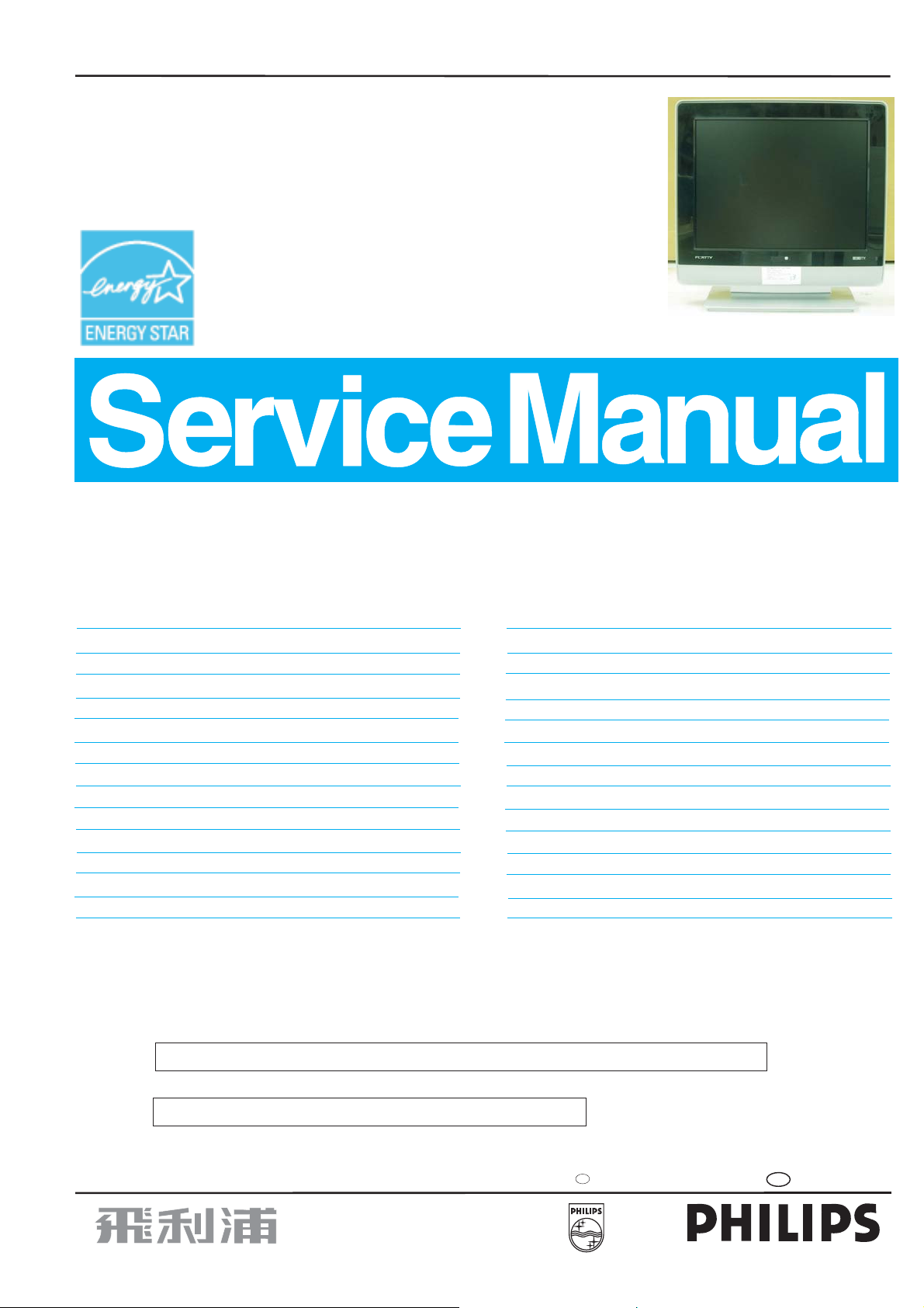
ME5P 15" & 20" LCDTV
Service
Service
Service
Family:
NAFTA-----ML1.1U AA
China/AP--ML1.1A AA
EU----------ML1.1E AA
TABLE OF CONTENTS
Horizontal frequencies
15" 30 - 49 KHz
20" 30 - 40 KHZ
Description Page
Important Safety Notice ------------------------------2
General Product Specification(15") ------------ 3~27
General Product Specification(20") ----------- 28~50
On-screen Display(OSD)------------------------ 51~52
Aging Mode ------------------------------------------- 53
Warning Message ------------------------------------ 54
Factory Mode ----------------------------------------- 55
Troubling Shooting ---------------------------------- 56
Panel Failure Mode ---------------------------------- 57
Wiring Diagram -------------------------------------- 58
Mechanical Instructions ------------------------ 59~60
Electrical Instructions -------------------------- 61~64
Display Adjustments -------------------------- 65~66
Safety Test Requirement ---------------------------- 67
SAFETY NOTICE
ANY PERSON ATTEMPTING TO SERVICE THIS CHASSIS MUST FAMILIARIZE HIMSELF WITH THE CHASSIS
AND BE AWARE OF THE NECESSARY SAFETY PRECAUTIONS TO BE USED WHEN SERVICING ELECTRONIC
EQUIPMENT CONTAINING HIGH VOLTAGES.
Description Page
DDC Instructions & DDC Data ------------------ 68~73
«
Firmware Upgrade for CPU --------------------- 74~75
Function Block Diagram-------------------------------76
Scaler Schematic Diagram & C.B.A -------------77~90
YPbPr-IN PCB Schematic Diagram & C.B.A ---- 91~93
KEY PCB Schematic Diagram & C.B.A. --------- 94~96
IR/LED PCB Schematic Diagram & C.B.A ----- 97~102
Power Control Schematic Diagram & C.B.A -103~105
Exploded View--------------------------------------- 106
Spare parts list --------------------------------107~109
Different Parts List --------------------------- 110~112
Repair Tips ------------------------------------ 113~114
Repair Flow Chart ---------------------------- 115~116
Direction for User ---------------------------- 117~151
CAUTION: USE A SEPARATE ISOLATION TRANSFORMER FOR THIS UNIT WHEN SERVICING.
REFER TO BACK COVER FOR IMPORTANT SAFETY GUIDELINES
Published by BCU Monitors Printed in Suzhou Copyright reserved Subject to modification S Sep. 07 2005
GB
3122 785 15681
Page 2
2
ME5P 15" & 20"
Go to cover page
Proper service and repair is important to the safe,
reliable operation of all Philips Consumer Electronics
Company** Equipment. The service procedures
recommended by Philips and described in this service
manual are effective methods of performing service
operations. Some of these service operations require
theuseoftoolsspeciallydesignedforthepurpose.The
specialtoolsshouldbeusedwhenandas
recommended.
Itisimportanttonotethatthismanualcontains
various CAUTIONS and NOTICES which should be
carefully read in order to minimize the risk of personal
injury to service personnel. The possibility exists that
improper service methods may damage the equipment.
It is also important to understand that these
CAUTIONS and NOTICES ARE NOT EXHAUSTIVE.
Philips could not possibly know, evaluate and advise
theservicetradeofallconceivablewaysinwhich
service might be done or of the possible hazardous
consequences of each way. Consequently, Philips has
not undertaken any such broad evaluation. Accordingly,
aservicerwhousesaserviceprocedureortoolwhich
is not recommended by Philips must first satisfy
himself thoroughly that neither his safety nor the safe
operationoftheequipmentwillbejeopardizedbythe
service method selected.
Important Safety Notice
TO ENSURE THE CONTINUED RELIABILITY OF THIS
PRODUCT, USE ONLY ORIGINAL MANUFACTURER'S
REPLACEMENT PARTS, WHICH ARE LISTED WITH
THEIR PART NUMBERS IN THE PARTS LIST SECTION
OF THIS SERVICE MANUAL.
Take care during handling the LCD module with
Backlight unit
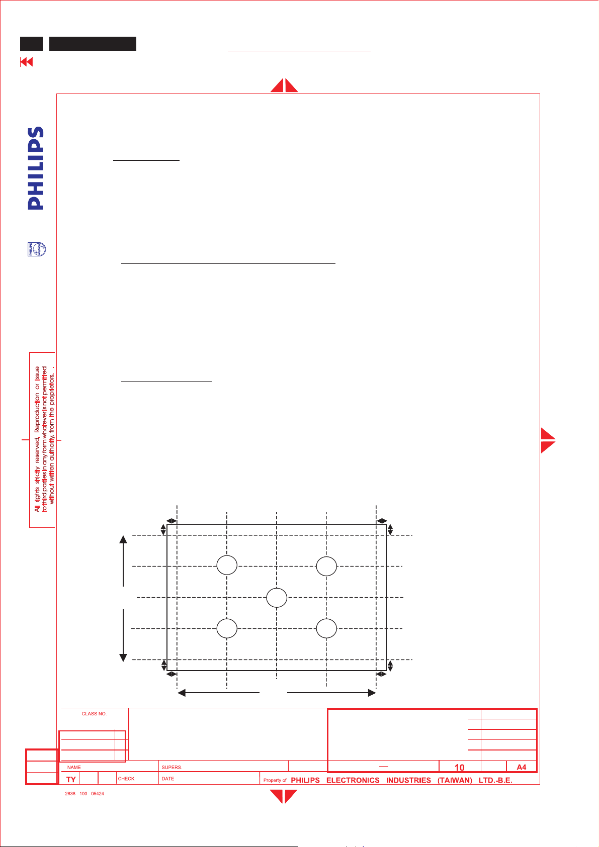
- Must mount the module using mounting holes
arranged in four corners.
-Donotpressonthepanel,edgeoftheframe
stronglyorelectricshockasthiswillresultin
damage to the screen.
-Donotscratchorpressonthepanelwithanysharp
objects,suchaspencilorpenasthismayresultin
damage to the panel.
- Protect the module from the ESD as it may damage
the electronic circuit (C-MOS).
- Make certain that treatment person s body are
grounded through wrist band.
-Donotleavethemoduleinhightemperatureandin
areasofhighhumidityforalongtime.
-Avoidcontactwithwaterasitmayashortcircuit
within the module.
- If the surface of panel become dirty, please wipe it
offwithasoftmaterial.(Cleaningwithadirtyor
rough cloth may damage the panel.)
* *Hereafter throughout this manual, Philips Consumer
Electronics Company will be referred to as Philips.
WARNING
Critical components having special safety
characteristics are identified with a by the Ref. No.
in the parts list and enclosed within a broken line*
(where several critical components are grouped in one
area)alongwiththesafetysymbol onthe
schematics or exploded views.
Use of substitute replacement parts which do not have
the same specified safety characteristics may create
shock, fire, or other hazards.
Under no circumstances should the original design be
modified or altered without written permission from
Philips. Philips assumes no liability, express or implied,
arising out of any unauthorized modification of design.
Servicer assumes all liability.
*BrokenLine
FOR PRODUCTS CONTAINING LASER :
DANGER-
CAUTION-
CAUTION-
Invisible laser radiation when open.
AVOID DIRECT EXPOSURE TO BEAM.
Use of controls or adjustments or
performance of procedures other than
those specified herein may result in
hazardous radiation exposure.
The use of optical instruments with this
product will increase eye hazard.
Page 3
Me5P 15" & 20"
GENERAL PRODUCT SPECIFICATION
ME5P 15" & 20"
Go to cover page
GENERAL PRODUCT SPECIFICATION
. 15inch Multifunction LCD monitor.
. PC 15 pins D-SUB analog interface.
. PC audio line in withmini-Jack
. DVI-I, TV Tuner, S-Video, RCAAVinput interface with R/L Audio-in.
. RCA connectorsfor YPbPr input
. NTSC, PAL TV system.
3
. PC graphicauto picture adjustment
. 14 user modes
. User friendly OSD menu
. User friendly remote controller
. DDC2B communication capability
. MAX. resolution 1024 x768 non-interlace at60Hz
. XGA 15inch color TFT LCD flat panel
. Easy tilt base
. Anti-glare to reduce lightreflection
. Power
management capability
. VESA standardwallmount kit (option)
2005-06-23
ISON KUO
15" ME5P TFT XGA LCD Monitor/TV
BRAND: PHILIPS
2005-06-23
24
590
1
Page 4
ME5P 15"&20"
4
Go to cover page
GENERAL PRODUCT SPECIFICATION
CONTENTS
1.0 Foreword
2.0 Product profile
2.1 LCD
2.2 Scanning frequencies
2.3 Video dot rate
2.4 Power input
2.5 Power consumption
2.6 Unit dimensions
2.7 Unit weight
2.8 Chin speaker
2.9 Functions
2.10 Ambient temperature
2.11 Regulatory compliance
3.0 Electrical characteristics
3.1 Interface signals cables
3.2 User interface
3.2.1 Keypad definition
3.2.2 Key Function definition
3.2.3 Remote control
3.3 PC and TV requirement
3.3.1 PC interface
3.3.1.1 Mode storing capacity
3.3.1.2 Horizontal scanning
3.3.1.3 Vertical scanning
3.3.1.4 Input connectors
3.3.1.5 Available timings
3.3.2 TV interface
3.3.2.1 TV special setting
3.3.3 Electric characteristics of I/O
3.4 Power input connection
3.5 Power management
3.6 Display identification
2005-06-23
ISON KUO
15" ME5P TFT XGA LCD Monitor/TV
BRAND: Philips
2005-06-23
24
590
2
Page 5
Me5P 15" & 20"
GENERAL PRODUCT SPECIFICATION
4.0Visual characteristics
4.1Test conditions
4.2Resolution
4.3Brightness
4.4Image size
4.4.1Actual display size
4.5Brightness uniformity
4.6PCwhite color adjustment
4.7 TV white color adjustment
4.8 TV picture centering
5.0Mechanical characteristics
5.1 Controls
5.2Unitdimension / weight
5.3Tilt base
5.4Transportation packages
5.4.1Shippingdimension / weight
5.4.2Block unit / palletization
ME5P 15" & 20"
Go to cover page
5
6.0Environmental characteristics
6.1Susceptibility ofdisplay to external environment
6.2Transportation tests
6.3Display disturbancesfrom external environment
7.0Reliability
7.1Meantime between failures
8.0 Quality assurancerequirements
8.1Acceptancetest
9.0Serviceability
15" ME5P TFT XGA LCD Monitor/TV
2005-06-23
ISON KUO
BRAND: PHILIPS
2005-06-23
24
590
3
Page 6
ME5P 15" & 20"”
6
Go to cover page
1.0 Foreword
GENERAL PRODUCT SPECIFICATION
This specification describes a 15" multifunction LCD Monitor, maximum
resolution up to 1024x768/60Hz non-interlaced.
2.0 Product profile
Philips 15” multifunction LCD Monitor can connect to PC ‘sanalogD-SUB
connector, and also support DVI, TV, S-Video, YPbPr/HD, and AV interface .
Meet world wide major TV system: NAFTA
2.1 LCD
Type NR. : T150XG01
Display area(mm) : 304.128(H) x 228.096(V) (15.0-inch diagonal)
Number of Pixels : 1024(H) x 768(V)
Pitch ( mm ) : 0.297(H) x 0.297(V)
Color pixel arrangement : RGB vertical stripes
Display operating mode : TN mode, normally white
Color depth : 16.2M colors ( 6 bits with FRC)
Brightness (cd/m^2) : 400nit(typ.) @ 6.5mA
Viewing angle(CR>10) : -70 º~ 70 º(H), -60º ~ 60º(V)(Typ.)
Surface treatment : Hard coating(3H) & AG
Electrical interface : 1ch LVDS (8bit)
Response Time : 12ms(typ.) (Tr+Tf)
Power Consumption(W) : 22(typ.) @ 6.5mA
Contrast ratio : Typical 500 : 1
Module size (mm) : 326.5(W) x 253.5(H) x 14.4(D) (typ.)
Module weight (g) : 1350 (max.)
Backlight : 4 CCFL
2005-06-23
ISON KUO
***Income inspections please refer to panel specification.
15" ME5P TFT XGA LCD Monitor/TV
BRAND: Philips
24
2005-06-23
590
4
Page 7
Me5P 15" & 20"
GENERAL PRODUCT SPECIFICATION
ME5P 15" & 20"
Go to cover page
2.2Scanningfrequencies :Hor. :30-49KHz
Ver.:56-62Hz
2.3Video dot rate : <66 MHz
2.4Power input:90-264Vac, 50/60 ± 2Hz
2.5Power consumption : Typ. 40 W
2.6UnitDimensions :378mm W x 370mm H x 156mm D (Incl. Pedestal)
2.7 Unit Weight:3.1 Kg
7
2.8 Chin
2.9Functions
speaker : 2 x 3 W
:
PC DVI-A analog interface with audio mini jack input (PC line in).
TV DVI-D digital interface usethe same audio mini jack inputof PC line in.
Tuner input.
S-Video ,RCA AV with L/R Audio-in andYPbPr with L/R Audio-in.
2.10 Ambient temperature: 0 - 35 °C
2.11 Regulatorycompliance:
Safety :CULand UL
UL 60065
EMI : FCC
FCC part 15 Class B
2005-06-23
ISON KUO
15" ME5P TFT XGA LCD Monitor/TV
BRAND: PHILIPS
2005-06-23
24
590
5
Page 8
8
ME5P 15" & 20"
Go to cover page
GENERAL PRODUCT SPECIFICATION
3.0Electrical characteristics
3.1Interface signals cables
VGA-DVI Interface Cable(option)
Length : 1.8 M +/- 50 mm
DVI-I Cable(option)
Length : 1.8 M +/- 50 mm
Stereo RCA R/L audio cable(option)
Length : 1.5M+/- 50 mm
S-video cable(option)
Length : 1.5M+/- 50 mm
AV cable(option)
Le
ngth : 1.5M +/- 50 mm
Mini Jack stereo cable(option)
Length : 1.5M+/- 50 mm
YPbPr cable(option)
Length : 1.5M +/- 50mm
3.2Userinterface
On screen display user control viakeypad and remotecontrol for PC,
and TV OSD.
3.2.1 Keypad definition
Top : key
pad Control
2005-06-23
ISON KUO
B C D
Left Right Menu Down
15" ME5P TFT XGA LCD Monitor/TV
BRAND: Philips
24
2005-06-23
E F
590
Up
6
Page 9
Me5P 15" & 20"
GENERAL PRODUCT SPECIFICATION
ME5P 15" & 20"
Go to cover page
Front : RC andpower switch
IR
A
Power
switch
3.2.1 Key Function definition:
Key Function VGA mode TV/video mode
9
<A> Power SoftPower SoftPower
<B> LeftLeft/Volume downLeft/Volume down
<C> RightRight/Volume up Right/Volume up
<D> Menu Call OSD menu Call OSD menu
<E> Down/channeldownDownDown/Channel Down
<F> Up/Channelup Up Up/Channelup
PC modeAuto adjustment hot key:Press <B>and<C>atthe sametime
andhold for 1 seconds.
1. Press “MENU”key to call main menu
2. By“Up/Down”to select fu
nction and“Left/Right” to adjust.
3.“Left/Right”alsois VolumeHotKey
4.“Up/Down”alsois Channel Hot Key(TV mode)
5. Press hot Key<B>and<C>can auto-adjust picture position, phase and
clock in PC mode.
Pow
er LED:
Normal working:Green
Power saving :Red.
2005-06-23
ISON KUO
15" ME5P TFT XGA LCD Monitor/TV
BRAND: PHILIPS
2005-06-23
24
590
7
Page 10

10
ME5P 15" & 20"
Go to cover page
GENERAL PRODUCT SPECIFICATION
3.2.1Remotecontrol
4
5
6
7
8
11
16
15
20
21
1.Power:PowerOn/Standby
2.Closed cap. :Closed caption on/off
1
2
3
10
9
12
13
14
19
17
18
22
3.SleepTimer:Sleeptimer
15,30,45,60,90,120,180,240,OFF
4.PIP : PIP size select (Small/Large/PBP)
5. SAP(2
6.States/Exit : Show states
7.Surroundmode:Incrediable surroundmode on/off
8.Format:Select display format
9. Menu :Main menu s
10.ACH :Recall previousCH
11.Left key :OSDleft key
12.Up key :OSDup key
13.Right key :OSDright key
14.Down key :OSDdown key
15.VOL+-:Volume Up/Down
16.Mute :Soundmutefunction
17.Smart Sound :Selectsoundeffect
18.Smart Picture :Selectpicture effect
(Personal/Rich/Natural/Soft/Multimedia)
19.CH+-:ChannelUp/Down
20. Number keys:(0~9)channelsetting
21.AV+ :Select for PC,DVI,TV,AV
22.Surf :Settingfavoritechannel
nd
audio):Soundmode select
(4:3,Expand 4:3,Compress 16:9)
elect
(Person
al/Voice/Music/Theatre)
,S-Video,HD
AllPCorTVOSDmenufunction couldbeaccomplished by remotecontrol.
3.3PCand TV requirement
3.3.1PCinterface
3.3.1.1Mode storingcapacity
Pre-load :11
User modes:14
3.3.1.2 Horizontalscanning
Sync polarity :Positive or Negative
Scanningf
15" ME5P TFT XGA LCD Monitor/TV
2005-06-23
ISON KUO
BRAND: Philips
2005-06-23
requency :30-49KHz
24
590
8
Page 11
Me5P 15" & 20"
GENERAL PRODUCT SPECIFICATION
3.3.1.3Vertical scanning
Syncpolarity :PositiveorNegative
Scanningfrequency :56-62Hz
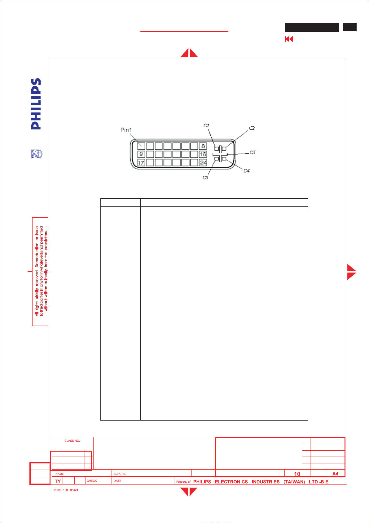
3.3.1.4Input connectors
Note the mark“*”for DVI-I to Dsub only
Pin No. Description
1TMDSdata2-
2TMDSdata2+
3TMDSdata2 shield
4NC
5NC
6 DDC clock
7 DDC data
8 * Analog V-sync
9TMDSdata1-
10 TMDS data1+
11 TMDS data1 shield
12 NC
13 NC
14 +5V
15 Ground(return for +5V and H/V-sync)
16 Hot plug detect
17 TMDS data018 TMDS data0+
19 TMDS data0 shield
20 NC
21 NC
22 TMDS clock shield
23 TMDS clock+
24 TMDS clock-
C1
C2 * Analog G
C3 * Analog B
C4 * Analog H-sync
C5 * Analog GND (Analog R, G, Breturn)
* Analog R
ME5P 15" & 20"
Go to cover page
11
2005-06-23
ISON KUO
15" ME5P TFT XGA LCD Monitor/TV
BRAND: PHILIPS
2005-06-23
24
590
9
Page 12
12
ME5P 15" & 20"
Go to cover page
GENERAL PRODUCT SPECIFICATION
3.3.1.5Available timings
Factory pre-load timing, size andcenteringareaccording to the reference timing
charts. List as below
Mode 3, 6,7,10 are preset modesthatshould pass QAinspection.
Mode 1
, 2, 4, 5,8,9,11 will run auto adjustment only, andW/O QA checking.
MODE NO. 12 3
RESOLUTION 640 x 350 720 x 400 640 x 480
Dot clock(MHz) 25.17528.321 25.175
f h31.469kHz 31.469kHz 31.469kHz
A (us ) 31.78(800 dots) 31.78(900dots) 31.778 (800 dots)
B (us ) 3.813(96 dots) 3.813(108dots) 3.813 ( 96 dots)
C (us ) 1.907(48dots) 1.907(54dots) 1.907(48dots)
D (us ) 25.42(640 dots) 25.42(720dots) 25.422 (640 dots)
E (us ) 0.636(16 dots) 0.636(18dots) 0.636 ( 16 dots)
fv 70Hz(70.09)70Hz(70.087) 60Hz ( 59.940 )
O (ms ) 14.27(449 lines) 14.27(449 lines) 16.683 (525 lines )
P (ms ) 0.064(2 lines) 0.064(2lines) 0.064 ( 2 lines )
Q(ms ) 1.875(59 lines) 1.080(34 lines) 1.049 ( 33 lines )
R (ms ) 11.12(350 lines) 12.71(400 lines) 15.253 (480lines )
S (ms ) 1.208(38 lines) 0.413(13 lines) 0.317(10 lines)
SYNC.H/V +/- -/+ -/-
POLARITY
SEP . SYNC YY Y
MODE NO. 45
RESOLUTION 640x480 640 x 480
Dot clock(MHz) 30.240 31.500
f h35.0kHz 37.500kHz
A (us ) 28.571(864 dots) 26.667(840 dots)
B (us ) 2.116( 64 dots) 2.032 ( 64 dots)
C (us ) 3.175( 96 dots) 3.810 ( 120 dots)
D (us ) 21.164(640 dots) 20.317(640 dots)
E (us ) 2.116( 64 dots) 0.508( 16 dots)
fv 66.7 HZ( 66.667
)
O (ms ) 15.000(525 lines ) 13.333 (500 lines)
P (ms ) 0.086( 3lines ) 0.080 ( 3lines)
Q(ms ) 1.114( 39 lines ) 0.427(16 lines)
R (ms ) 13.714(480 lines ) 12.80 (480lines)
S (ms ) 0.086( 3 lines ) 0.027(1line)
SYNC.H/V +/+ -/POLARITY Or -/-
SEP . SYNC YY
15" ME5P TFT XGA LCD Monitor/TV
75Hz (75 )
2005-06-23
ISON KUO
BRAND: Philips
2005-06-23
24
590
10
Page 13
Me5P 15" & 20"
GENERAL PRODUCT SPECIFICATION
ME5P 15" & 20"
Go to cover page
A:H-Total O:V-Total
B:H-Syncwidth P:V-Syncwidth
C:H-Back porch Q :.V- Back porch
D:H-Video width R : V- Video length
E : H- Front porch S:.V- Front porch
MODE NO. 6 78
RESOLUTION 800 x 600 800 x 600 800 x 600
Dot clock(MHz) 36.000 40.000 49.500
fh 35.156kHz 37.879kHz 46.875kHz
A (us) 28.44 (1024 dots) 26.40 (1056 dots) 21.333 (1056dots)
B (us) 2.000 (72 dots) 3.200 ( 128dots) 1.616 (80 dots)
C (us) 3.556 ( 128dots) 2.200 (88dots) 3.232 ( 160 dots)
D (us) 22.22 (800 dots) 20.00 (800 dots) 16.162 (800 dots)
E (us) 0.667( 24 dots) 1.000 ( 40 dots) 0.323 ( 16 dots)
fv 56Hz(56.25 ) 60Hz( 60.316)75Hz( 75.000)
O (ms ) 17.78 (625 lines) 16.58(628lines) 13.333 (625lines)
P (ms) 0.057(2 lines) 0.106 ( 4 lines) 0.064 ( 3 lines)
Q(ms) 0.626 ( 22 lines) 0.607(23 lines) 0.448(21 lines)
R (ms) 17.07(600 lines) 15.84 (600 lines) 12.80 (600lines)
S (ms) 0.028(1 line ) 0.026 ( 1 line ) 0.021 ( 1 line )
SYNC. H/V + / ++/ ++/ +
POLARITY
SEP . SYNC YYY
13
MODE NO. 910 11
RESOLUTION 832 x 624 1024 x768 1024 x768
Dot clock(MHz) 57.28065.000 78.750
fh 49.722kHz 48.363kHz 60.023kHz
A (us) 20.11 (1152dots) 20.677(1344 dots) 16.66 (1312dots)
B (us) 1.117( 64 dots) 2.092(136 dots) 1.219 ( 96 dots)
C (us) 3.911 ( 224 dots) 2.462(160 dots) 2.235 ( 176 dots)
D (us) 14.52 (832 dots) 15.754(1024 dots) 13.003 (1024dots)
E (us) 0.559 ( 32 dots) 0.369(24 dots) 0.203 ( 16 dots)
fv 75Hz( 74.546) 60.004Hz75Hz( 75.029)
O (ms ) 13.41 (667lines) 16.666(806 lines) 13.328(800 lines)
P (ms) 0.060 ( 3 lines) 0.124(6 lines) 0.050 ( 3 lines)
Q(ms) 0.784 ( 39 lines) 0.600(29 lines) 0.466 ( 28lines)
R (ms) 12.55 (624 lines) 15.880(768lines) 12.795 (768lines)
S (ms) 0.020 ( 1 lines) 0.062(3 lines) 0.017(1 line )
SYNC. H/V - / - -/- +/+
POLARITY
SEP . SYNC YY Y
15" ME5P TFT XGA LCD Monitor/TV
2005-06-23
ISON KUO
BRAND: PHILIPS
2005-06-23
24
590
11
Page 14
14
ME5P 15" & 20"
Go to cover page
GENERAL PRODUCT SPECIFICATION
3.3.2TVinterface:
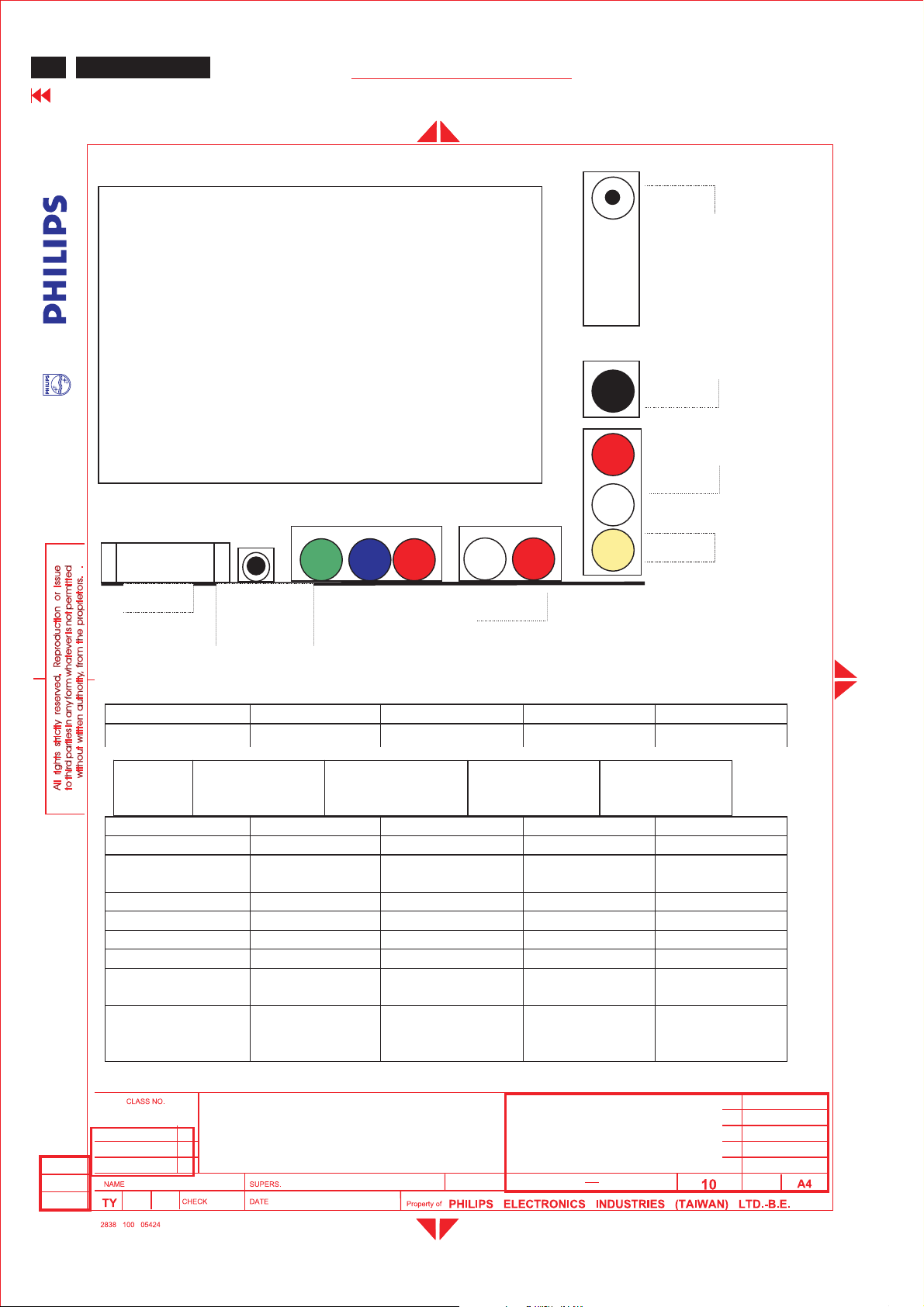
ME5P-15inchTVfunction include
1. Tuner (EUR, PanAmerica, AP model
and China)
2. S-video2.
3. CVBS (or AV)(RCA connectors)
4. Audio R/L input (RCA connectors)
5.YPbPr andaudio(RCA connectors)
6. DVI-Audio IN
7.
DVI-I
LOCATION:
DVI DVI-
Audio IN
Tuner
S-video
R
Audio
L
L
Y
Pb
Pr
R
Audio
CVBS
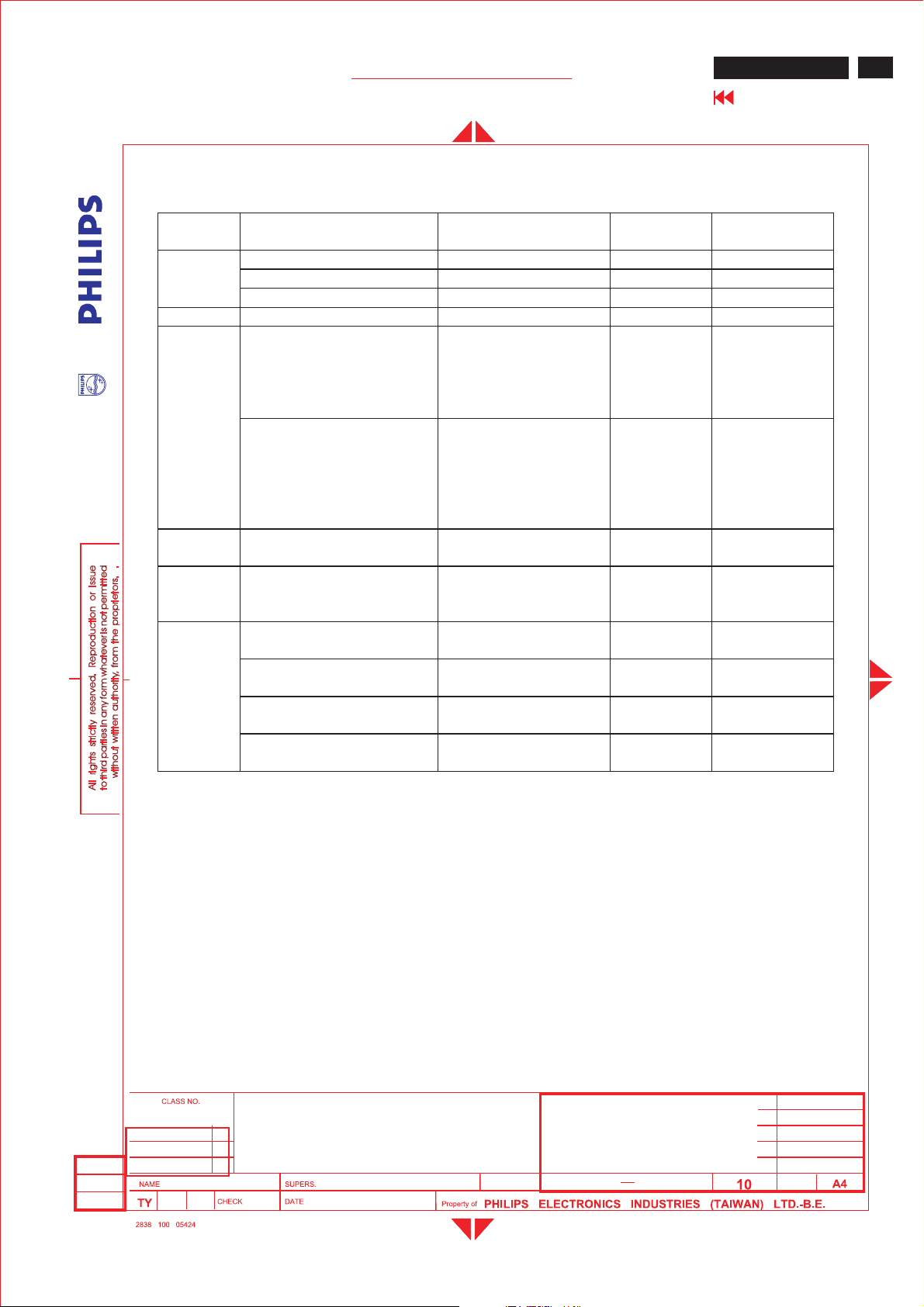
Following table is the deviation ofmain TV system.
Item W EUROPE America AP China
TV Color system PAL, SECAM NTSC PAL/NTSC, PAL
Tuner
TV system B/G, D/K, I, LM B/G, NTSC-M D/K
Sounddecoder MSP3415G MSP3445G MSP3415G MSP3415G
CVBS,YC
Color system
ScalerMCU WE version NAFTA version AP version Chinaversion
Closed caption N Y NN
V-chip N Y NN
TeletextN N N N
Remote
controller(RC5)
Channelnumber 100 US Air 68, cable
FQ1216ME/I
Picturecarrier
38.9MHz
Multi Multi Multi Multi
NAFTA version NAFTA version NAFTA version NAFTA version
15" ME5P TFT XGA LCD Monitor/TV
FQ1236/F
Picturecarrier
45.75MHz
125
FQ1216PN
Picturecarrier
38.9MHz
100 100
FQ1256/I H-3
Picturecarrier
38MHz
2005-06-23
ISON KUO
BRAND: Philips
2005-06-23
24
590
12
Page 15
Me5P 15" & 20"
GENERAL PRODUCT SPECIFICATION
Following tableis the detail TV systemlist.
TV
system
M
N4.5BTSC-stereo+SAP PAL Argentina
B/G
L6.5/5.85 AM-Mono/
I6.0/6.552 FM-Mono/
D/K
Position ofsoundcarrier
(MHz)
4.5/4.724212 FM-Stereo(A2) NTSC Korea
4.5FM-FM(EIA-J) NTSC Japan
4.5BTSC-stereo+SAP NTSC USA
5.5/5.7421875FM-stereo(A2) PAL Germany,
5.5/5.85 FM-Mono/
6.5/6.2578125 FM-Stereo
6.5/6.7421875FM-Stereo
6.5/5.7421875FM-Stereo
6.5/5.85 FM-Mono/
Soundsystem Color
system
PAL Belgium,
NICAM
SECAM-L France
NICAM
PAL GreatBritain,
NICAM
SECAM-
(A2,D/K1)
(A2,D/K2)
(A2,D/K3)
NICAM(D/K,NICAM)
East
PAL None
SECAMEast
PAL China,
ME5P 15" & 20"
Go to cover page
Country
Austria,
Switzerland,
Italy,
Netherlands,
Spain,
Denmark,
Finland,
Norway,
Sweden.
HongKong,
Ireland
Slovak. Rep.
Poland
Hungary
15
3.3.2.1TVspecial setting:
CloseCaption, V-chip(NAFTA Tuner ,CVBS in put sourceonly)
15" ME5P TFT XGA LCD Monitor/TV
2005-06-23
ISON KUO
BRAND: PHILIPS
2005-06-23
- CC-1 .. CC-4 decodinganddisplay
-TXT1..TXT4 Text mode
-NoExtended Data Services(EDS)
-Support violenceratingandchecking
-A
utomatic CC-1 selection at user mute
24
590
13
Page 16
16
ME5P 15" & 20"
Go to cover page
GENERAL PRODUCT SPECIFICATION
3.3.3Electriccharacteristicsof I/O
DVI :
Analog(PC mode)
- Impedance: 75
-Level:700mV
-Sync : TTL level, separate sync, + or - polarity
Digitalinterface with 4 channels TMDS signal
DVI-stereoinput
- Audio: Impedance >
- InputLevel: 500mVrms
- (Speakeroutput3WwhenInputlevel > 500mVrms and Volume
control at100%)
RCA A/V,andaudio R+Linput
-Location: Rearside
- CVBS: 75impedance.
-Audio: Imp
InputLevel: 500mVrms (Speakeroutput3WwhenInputlevel >
500mVrms and Volume control at100%)
- ESD-protected :15kV
Headphone
-Location : On scaler board.
-Peripherals : Headphones with impedance
between 8 -600
-Features:Whe
-Sound is muted.
-Volume control: with the loudspeaker volume.
-Connector type:3.5 mm stereo Jack, with switch
-Specifications : - Output: 32
-Sound is the same as from the loudspeakers.
- ESD-protected :15kV
YPbPr:
-Location:Rearside
-Connector type: RCA connectors
- Input:75
S-video:
-Location:Rearside
- Input:75
W
10 k
W
W
DC coupled signals 1Vpp
(Sync:300mV,video:700mV)
edance > 10 k
W
W
nheadphone plug is connected, loudspeaker
W
10 mW
W
W
2005-06-23
ISON KUO
15" ME5P TFT XGA LCD Monitor/TV
BRAND: Philips
2005-06-23
24
590
14
Page 17
Me5P 15" & 20"
GENERAL PRODUCT SPECIFICATION
ME5P 15" & 20"
Go to cover page
3.4Power input connection
AC/DC adapter : +16V DC/ 3.75A ( AC input100~240V )
AC Power cordlength :1.8 M
Power cord type:3leads power cordwithprotectiveearthplug.
3.5Power management
PC mode
The power consumption and the status indication of the set
withpower management function are as follows,
Power Spec
STATUS Horizontal Vertical 120VAC230V
AC
LED
ActivePulsePulseTypical 40 W Green
Sleep No PulseNoPulse < 1 W<1 W Red
Power switch off --< 1 W<1 W -
TV mode
The power consumption and the status indication of the set
withpower management function are as follows,
Power Spec
STATUS 120VAC230V
AC
LED
ActiveTypical 40 W Green
Sleep<1 W<1 W Red
Power switch off < 1 W<1 W -
In Monitor power savingmode
,which no H&V sync, or absent either H-sync or V-sync
input via VGA connector. The monitor will enter “Monitor savingmode”. The way to wake
up or change source:
17
1.“So urce”key on remote controlà changetoTVsource directly.
In TV
power savingmode,which switched off by RC “Standby”key, SLEEP TIMER
function or no TV signal input for 30 minutes, the monitor will enter “TV standby mode”,
and LED shows amber color. The way to wake up:
1.“So urce”key on remote controlà changetoTVs
ource directly.
2.“Standby”key on remote control.
3.6Display identification
In accordance with DDC requirement –“DDC2B”.
15" ME5P TFT XGA LCD Monitor/TV
BRAND: PHILIPS
2005-06-23
ISON KUO
2005-06-23
24
590
15
Page 18
18
ME5P 15" & 20"
Go to cover page
4.0Visual c h aract eristics
GENERAL PRODUCT SPECIFICATION
4.1Test c onditions
Unless otherwise specified, this specification is defined underthefollowing
conditions.
(1) In p utsignal:Asdefined in 3.3.1.2, 1024 x768 non -interlaced mode
(48.36 KHz), signalsources must have 75ohm outp ut
impedance.
(2) Lumin ance setting:Controlstobe setto450Nits(typical)with
full screen100%duty cyclewhite signal.
(3)Warmup: More than30min utes afterpoweronwith signalsupplied.
(4) Ambient light: 400 -- 600 lux.
(5) Ambient t
4.2Resolution
emperature:25± 2 °C
Mode 3, 6,7,10 are preset modesthatshould pass QAinspection.
Mode 1, 2, 4, 5,8,9,11 will run auto adjustment only, andW/O QA checking.
# Resolution Frequency Pixelrat
1 640X350 31.5K/70HZ 25.175 (+/-) IBM VGA
2 720X400 31.5K/70HZ 28.322 (-/ +) IBM V G A
3 640X48031.5K/6 0 HZ 25.175 (-/-) IBM VGA
4 640X48035.0K/6 7HZ 30.24 (-/-) MAC
5 640X48037.5K/75HZ 31.501 (-/-) VESA
6 800X600 35.2K/56HZ 36 (+/+) VESA
7800X600 37.9K/60HZ 40 (+/+) VESA
8800X600 46.9K/75HZ 49.498(+/+) VESA
9 832X624 49.7K/75HZ 57.28(+/+) MAC
10 1024X768 48.4K/60HZ 65 (-/-) VESA
11 1024X768 60.0K/75HZ 78.75 (-/-) VESA
4.3Brig htness:
Typical450nitsat maximum contrast and Brightness.(at centerof the
screen , Fig. 1 )
e Sync Comment
4.4Image size
4.4.1Actual display size 30 4.1 x 228.1mm
2005-06-23
ISON KUO
15" ME5P TFT XGA LCD Monitor/TV
BRAND: Philips
2005-06-23
24
590
16
Page 19
Me5P 15" & 20"
GENERAL PRODUCT SPECIFICATION
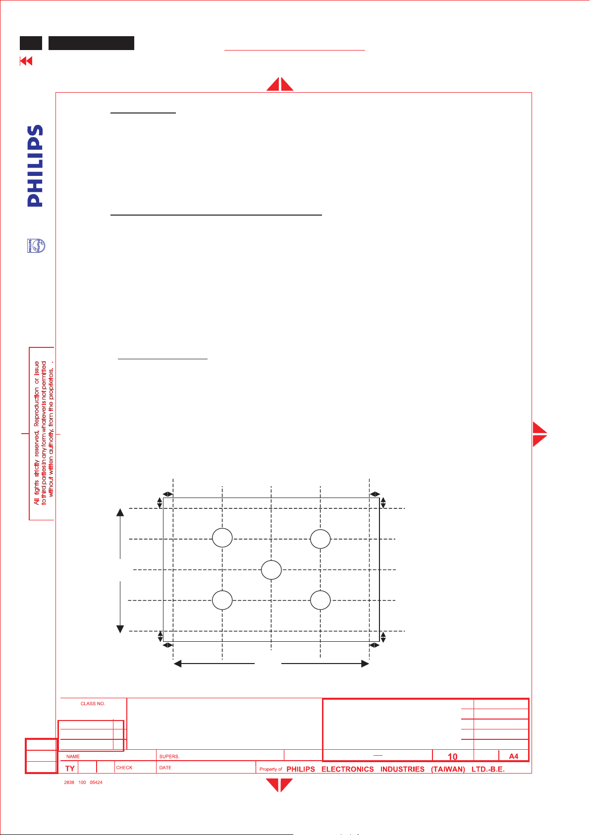
4.5Brightness uniformity
Set contrast at 100%and turn the brightness to Max. (At original color)
Apply theFig 1, it should comply with the follo wingformula:
Minimum luminanceoffive points(brightness)
Maximum luminanceo
4.6PCwhite color adjustment
There are three factorypreset white color 8500K
Apply full white pattern,withbrightness in 50 %position
and the contrast controlat50%position.
The1931CIEChromaticity(co lor triangle)di
coordinate for the screen center should be:
8500K CIE coordinates X = 0.292 +/- 0.030
Y=0.293 +/- 0.030
ffive points(brightness)
agram (x,y)
ME5P 15" & 20"
Go to cover page
> 75%
19
4.7TVwhite color adjustment
There is one factorypreset white co lor x=0.292 ± 0.030;y=0 .293 ± 0.030 for TV
RF sig
nal with the1931CIEChromaticitydiagram (x,y) coordinate ,FLUKE54200
color temp pattern, Smart picture is Personal.
4.8 TV picture centering
Use CVBS (PAL and NTSC) input withcross hatch pattern to check the picture
centeringandshould be
Left(size)-right(size)<+/- 3mm.
Up(size)-down(size)<+/- 3mm.
2005-06-23
ISON KUO
15" ME5P TFT XGA LCD Monitor/TV
BRAND: PHILIPS
2005-06-23
24
590
17
Page 20
20
ME5P 15" & 20"
Go to cover page
GENERAL PRODUCT SPECIFICATION
5.0Mechanical characteristics
5.1 Controls
Top Control :
-Upkey
-Down key
-Menukey
-Right key
-Left key
Front - RC sensor
-DCpowerswitch
RearI/O :
-DCinlet
-DVIinput
-Tunerinput
- CinchCVBSinput (AV)
- CinchAudio input
(S-video and CVBS use same audio)
-S-Videoinput
-Minijack PC audio input
- YPbPr,
-Audio
for YPbPr
2005-06-23
ISON KUO
5.2Unitdimension / Weight
Set dimension (incl. pedestal):478mm W x 370mm H x 156mm D
Net weight : 4.2 Kg
5.3 Tilt base
Tilt angle : 0 to 10 degree
5.4Transportation packages
5.4.1 Shippingdimension/ Weight
Carton dimension : 41
7mm W x 200mm H x 426mm D
Gross weight : 5.8 Kg
5.4.2Block unit / Palletization (Sea shipment)
layers/block
sets/layer sets/block unit
10 6/4 60/40
15" ME5P TFT XGA LCD Monitor/TV
BRAND: Philips
24
2005-06-23
590
18
Page 21
Me5P 15" & 20"
GENERAL PRODUCT SPECIFICATION
6.0Environmental characteristics
The followingsectionsdefine the interference andsusceptibility
condition limits that mightoccur between external environment and
the display device.
6.1Susceptibility ofdisplay to external env
Operating
-Temperature : 0 to 35
-Humidity : 80%max
-Altitude : 0-3658m
-Airpressure : 600-1100 mBAR
Storage
-Temperature : -20 to 60
-Humidity :95%max(<40 )
-Altitude : 0-12192m
-Airpressure : 300-1100 mBAR
ironment
ME5P 15" & 20"
Go to cover page
21
** Note: recommendat 0 to 35°C, Humidityless than60%
6.2Transportation tests
Standard UAN-D1534/01
Height60and 25 cm
1st: bottom*3 ,(60cm) drop
Drop Sequence followed, left,front, right, rear, topdrop(25cm)
Test
Electrical function ok
TestMechanical function ok
ResultNoserious damageonset appearance
(room temp./-10° c, humidity70 %)
Sequence --- PACKAGING
Vibration 7 Hz, 1.05G, 30 min.for transport direction only
TestTestElectrical function ok
ResultMechanical function ok
No serious damageonset appearance
6.3Display disturbancesfrom external environment
According to IEC 801-2 for ESD disturbances
2005-06-23
ISON KUO
15" ME5P TFT XGA LCD Monitor/TV
BRAND: PHILIPS
2005-06-23
24
590
19
Page 22
22
ME5P 15" & 20"
Go to cover page
GENERAL PRODUCT SPECIFICATION
7.0Reliability
7.1MeanTime BetweenFailures
System MTBF (Excluding the LCD panel and CCFL) :50,000 hrs
CCFL MTBF : 50,000 hrs
8.0 Qualityassurance requirements
8.1Acceptance test
According to MIL-STD-105D Control II level
AQL:0.65 (major)
2.5 (minor)
(Pleasealso refertoannual qualityagreement)
9.0Serviceability
The serviceability of this monitor shouldfulfill the requirements which are
prescribed in UAW-0346 andmust be checked with thecheck list UAT-0361.
Fig 1: Brightness and Uniformitymeasure points
H/10
b
a
1
V
3
a
b
H/2
5
H
9H
/10
2
4
b
a
V/
10
V/2
9V/
10
a
b
2005-06-23
ISON KUO
15" ME5P TFT XGA LCD Monitor/TV
BRAND: Philips
2005-06-23
24
590
20
Page 23
Me5P 15" & 20"
GENERAL PRODUCT SPECIFICATION
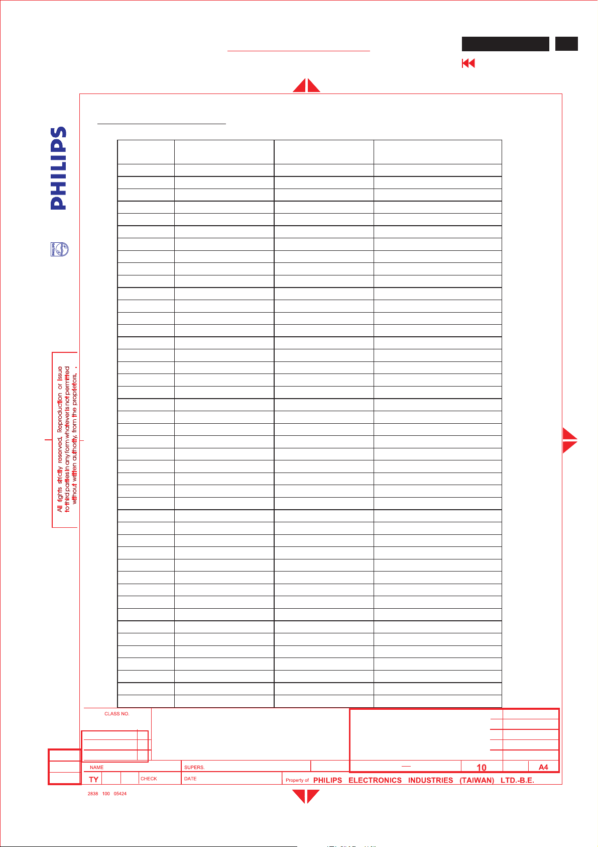
Table1.
NAFTA TV channels
US- Air broadcast channel
Broadcast
Channel
255.25 59.75 54-60
361.25 65.75 60-66
467.25 71.75 66-72
5 77.25 81.75 76-82
6 83.25 87.75 82-88
7 175.25 179.75174-180
8 181.25 185.75180-186
9187.25 191.75186-192
10 193.25 197.75 192-198
11 199.25 203.75198-204
12 205.25 209.75 204-210
13 211.25 215.75 210-216
14 471.25 475.75470-476
15 477.25 481.75476-482
16 483.25 487.75482-488
17 489.25 493.75488-494
18 495.25 499.75 494-500
19 501.25 505.75 500-506
20 507.25 511.75 506-512
21 513.25 517.75 512-518
22 519.25 523.75518-524
23 525.25 529.75 524-530
24 531.25 535.75 530-536
25 537.25 541.75 536-542
26 543.25 547.75 542-548
27 549.25 553.75548-554
28 555.25 559.75 554-560
29 561.25 565.75 560-566
30 567.25 571.75 566-572
31 573.25 577.75572-578
32 579.25 583.75578-584
33 585.25 589.75584-590
34 591.25 595.75 590-596
35 597.25 601.75 596-602
36 603.25 607.75 602-608
37 609.25 613.75608-614
38 615.25 619.75 614-620
39 621.25 625.75 620-626
40 627.25 631.75 626-632
41 633.25 637.75 632-638
42 639.25 643.75638-644
43 645.25 649.75 644-650
44 651.25 655.75 650-656
45 657.25 661.75 656-662
Video Carrier (MHz) Audio Carrier
(MHz)
Range
(MHz)
ME5P 15" & 20"
Go to cover page
23
2005-06-23
ISON KUO
15" ME5P TFT XGA LCD Monitor/TV
BRAND: PHILIPS
2005-06-23
24
590
21
Page 24
24
ME5P 15" & 20"
Go to cover page
GENERAL PRODUCT SPECIFICATION
46 663.25 667.75 662-668
47 669.25 673.75668-674
48 675.25 679.75674-680
49 681.25 685.75680-686
50 687.25 691.75686-692
51 673.25 697.75 692-698
52 699.25 703.75698-704
53 705.25 709.75 704-710
54 711.25 715.75 710-716
55 717.25 721.75 716-722
56 723.25 727.75 722-728
57729.25 733.75 728-734
58735.25 739.75 734-740
59 741.25 745.75 740-746
60 747.25 751.75 746-752
61 753.25 757.75 752-758
62 759.25 763.75 758-764
63 765.25 769.75 764-770
64 771.25 775.75 770-776
65 777.25 781.75 776-782
66 783.25 787.75 782-788
67789.25 793.75 788-794
68795.25 799.75 794-800
69 801.25 805.75 800-806
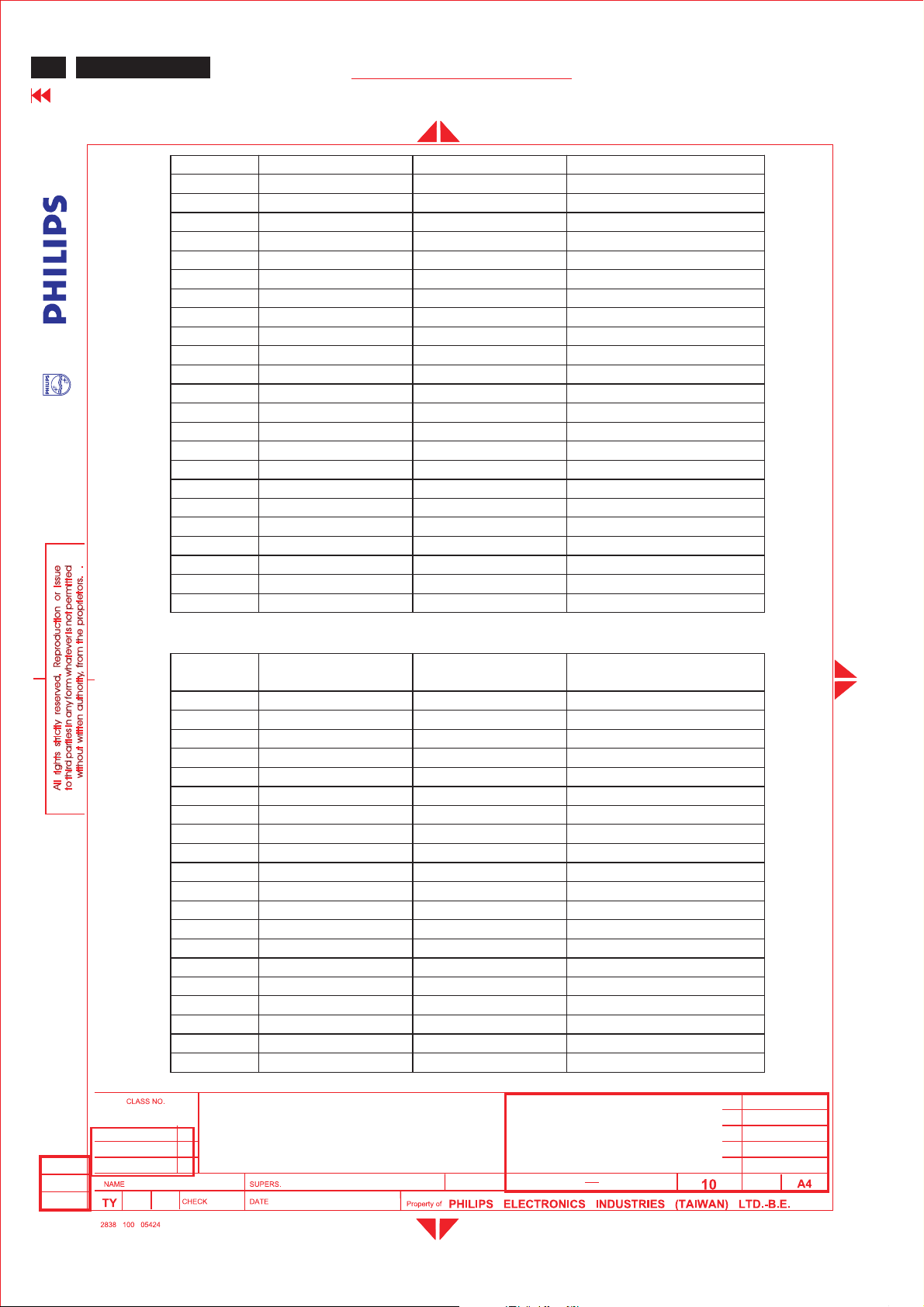
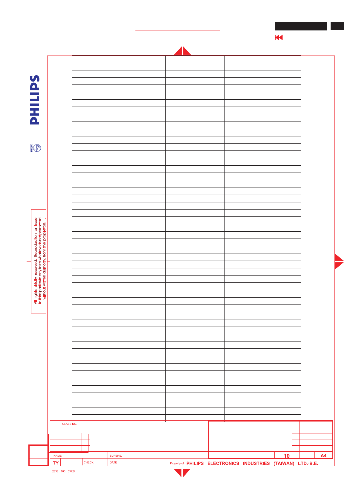
US-Cablechannel
Cable
Channel
255.25 59.75 54-60
361.25 65.75 60-66
467.25 71.75 66-72
1 73.25 77.75 72-78
5 79.25 83.75 76-82
6 85.25 89.75 82-88
95 91.25 95.75 90-96
96 97.25 101.75 96-102
97 103.25 107.75 102-108
98 109.25 113.75108-114
99 115.25 119.75 114-120
14 121.25 125.75 120-126
15 127.25 131.75 126-132
16 133.25 137.75 132-138
17 139.25 143.75138-144
18 145.25 149.75 144-150
19 151.25 155.75 150-156
20 157.25 161.75 156-162
21 163.25 167.75 162-168
22 169.25 173.75168-174
Video carrier
MHz
Audio carrier
MHz
Range
MHz
2005-06-23
ISON KUO
15" ME5P TFT XGA LCD Monitor/TV
BRAND: Philips
2005-06-23
24
590
22
Page 25
Me5P 15" & 20"
GENERAL PRODUCT SPECIFICATION
7 175.25 179.75174-180
8 181.25 185.75180-186
9187.25 191.75186-192
10 193.25 197.75 192-198
11 199.25 203.75198-204
12 205.25 209.75 204-210
13 211.25 215.75 210-216
23 217.25 221.75 216-222
24 223.25 227.75 222-228
25 229.25 233.75228-234
26 235.25 239.75 234-240
27 241.25 245.75 240-246
28 247.25 251.75 246-252
29 253.25 257.75 252-258
30 259.25 263.75258-264
31 265.25 269.75 264-270
32 271.25 275.75270-276
33 277.25 281.75276-282
34 283.25 287.75282-288
35 289.25 293.75288-294
36 295.25 299.75 294-300
37 301.25 305.75 300-306
38 307.25 311.75 306-312
39 313.25 317.75 312-318
40 319.25 323.75318-324
41 325.25 329.75 324-330
42 331.25 335.75 330-336
43 337.25 341.75 336-342
44 343.25 347.75 342-348
45 349.25 353.75348-354
46 355.25 359.75 354-360
47 361.25 365.75 360-366
48 367.25 371.75 366-372
49 373.25 377.75372-378
50 379.25 383.75378-384
51 385.25 389.75384-390
52 391.25 395.75 390-396
53 397.25 401.75 396-402
54 403.25 407.75 402-408
55 409.25 413.75408-414
56 415.25 419.75 414-420
57 421.25 425.75 420-426
58 427.25 431.75 426-432
59 433.25 437.75 432-438
60 439.25 443.75438-444
61 445.25 449.75 444-450
62 451.25 455.75 450-456
63 457.25 461.75 456-462
64 463.25 467.75 462-468
65 469.25 473.75468-474
15" ME5P TFT XGA LCD Monitor/TV
ME5P 15" & 20"
Go to cover page
25
2005-06-23
ISON KUO
BRAND: PHILIPS
2005-06-23
24
590
23
Page 26
26
ME5P 15" & 20"
Go to cover page
GENERAL PRODUCT SPECIFICATION
66 475.25 479.25 474-480
67 481.25 485.75480-486
68 487.25 491.75486-492
69 493.25 497.75 492-498
70 499.25 503.75498-504
71 505.25 509.75 504-510
72 511.25 515.75 510-516
73517.25 521.75 516-522
74 523.25 527.75 522-528
75 529.25 533.75528-534
76 535.25 539.75 534-540
77 541.25 545.75 540-546
78 547.25 551.75 546-552
79 553.25 557.75 552-558
80 559.25 563.75558-564
81 565.25 569.75 564-570
82571.25 575.75570-576
83577.25 581.75576-582
84583.25 587.75582-588
85589.25 593.75588-594
86 595.25 599.75 594-600
87 601.25 605.75 600-606
88 607.25 611.75 606-612
89 613.25 617.75 612-618
90 619.25 623.75618-624
91 625.25 629.75 624-630
92 631.25 635.75 630-636
93 637.25 641.75 636-642
94 643.25 647.75 642-648
100 649.25 653.75648-654
101 655.25 659.75 654-660
102 661.25 665.75 660-666
103 667.25 671.75 666-672
104 673.25 677.75672-678
105 679.25 683.75678-684
106 685.25 689.75684-690
107 691.25 695.75 690-696
108 697.25 701.75 696-702
109 703.25 707.75 702-708
110 709.25 713.75 708-714
111 715.25 719.75 714-720
112 721.25 725.75 720-726
113 727.25 731.75 726-732
114 733.25 737.75 732-738
115 739.25 743.75 738-744
116 745.25 749.75 744-750
117751.25 755.75 750-756
118757.25 761.75 756-762
119 763.25 767.75 762-768
120 769.25 773.75 768-774
121 775.25 779.75 774-780
122 781.25 785.75 780-786
123 787.25 791.75 786-792
124 793.25 797.75 792-798
125 799.25 803.75 798-804
15" ME5P TFT XGA LCD Monitor/TV
2005-06-23
ISON KUO
BRAND: Philips
2005-06-23
24
590
24
Page 27
Me5P 15"&20"
GENERAL PRODUCT SPECIFICATION
ME5P 15"&20"
Go to cover page
GENERAL PRODUCT SPECIFICATION
. 20inch Multifunction LCD monitor.
. PC 15 pins D-SUB analog interface.
. PC audio line in with mini-Jack
. DVI-I, TV Tuner, S-Video, RCA AV input interface with R/L Audio-in.
. RCA connectors for YPbPr input
. NTSC, PAL TV system.
27
. PC graphic auto picture adjustment
. 14 user modes
. User friendly OSD menu
. User friendly remote controller
. DDC2B communication capability
. MAX. resolution 800 x 600 non-interlace at 60 Hz
. SVGA 20inch color TFT LCD flat panel
. Easy tilt base
. Anti-glare to reduce light reflection
. Power management capability
2005-06-22
ISON KUO
20" ME5P TFT LCD TV
BRAND: PHILIPS
2005-06-22
24
590
1
Page 28
28
ME5P 15"&20"
Go to cover page
GENERAL PRODUCT SPECIFICATION
CONTENTS
1.0 Foreword
2.0 Product profile
2.1 LCD
2.2 Scanning frequencies
2.3 Video dot rate
2.4 Power input
2.5 Power consumption
2.6 Unit dimensions
2.7 Unit weight
2.8 Chin speaker
2.9 Functions
2.10 Ambient temperature
2.11 Regulatory compliance
3.0 Electrical characteristics
3.1 Interface signals cables
3.2 User interface
3.2.1 Keypad definition
3.2.2 Key Function definition
3.2.3 Remote control
3.3 PC and TV requirement
3.3.1 PC interface
3.3.1.1 Mode storing capacity
3.3.1.2 Horizontal scanning
3.3.1.3 Vertical scanning
3.3.1.4 Input connectors
3.3.1.5 Available timings
3.3.2 TV interface
3.3.2.1 TV special setting
3.3.3 Electric characteristics of I/O
3.4 Power input connection
3.5 Power management
3.6 Display identification
4.0 Visual characteristics
4.1 Test conditions
4.2 Resolution
4.3 Brightness
4.4 Image size
4.4.1 Actual display size
4.5 Brightness uniformity
4.6 PC white color adjustment
4.7 TV white color adjustment
2005-06-22
ISON KUO
20" ME5P TFT LCD TV
BRAND: PHILIPS
2005-06-22
24
590
2
Page 29
Me5P 15"&20"
GENERALPRODUCT SPECIFICATION
4.8 TV picture centering
5.0 Mechanical characteristics
5.1 Controls
5.2 Unit dimension / weight
5.3 Tilt base
5.4 Transportation packages
5.4.1 Shipping dimension / weight
5.4.2 Block unit / palletization
6.0 Environmental characteristics
6.1 Susceptibility of display to external environment
6.2 Transportation tests
6.3 Display disturbances from external environment
ME5P 15"&20"
Go to cover page
29
7.0 Reliability
7.1 Mean time between failures
8.0 Quality assurance requirements
8.1 Acceptance test
9.0 Serviceability
2005-06-22
ISON KUO
20" ME5P TFT LCD TV
BRAND: PHILIPS
2005-06-22
24
590
3
Page 30
30
ME5P 15" & 20"
Go to cover page
1.0 Foreword
2.0 Product profile
GENERAL PRODUCT SPECIFICATION
This specification describes a 20" multifunction LCD Monitor, maximum
resolution up to 800x600/60Hz non-interlaced.
Philips 20" multifunction LCD Monitor can connect to PC ‘s analog DSUB connector, and
also support DVI, TV, S-Video, ,YPbPr/HD, and AV interface .
Meet world wide major TV system: NAFTA
2.1 LCD :
Type NR. :A201SN02 (AUO)
Display area(mm) : 408(H) x 306(V) (20.1-inch diagonal)
Display mode : TN type, Normal white + SWV film
Number of Pixels : 800(H) x 600(V)
Pitch ( mm ) : 0.51(H) x 0.51(V)
Color pixel arrangement : RGB vertical stripes
Display mode : Normally white TN
Number of color : 16.7M ( 8 bits)
Brightness (cd/m^2) : 450nit(typ.)
Viewing angle : -80
Response time : 16ms typ. (Tr+Tf)
Surface treatment : Anti-Glare type
Electrical interface : TTL (1 port)
Contrast ratio : Typical 500 : 1
Overall dimension (mm) : 448(W) x 347(H) x 23(D)(max.)
Module weight (g) : 3500
Backlight : 6 CCFL
** Income inspection, please refer to panel specification.**
o
~80o(H), -60o~60o(V)(Typ.)
2005-06-22
ISON KUO
2.2 Scanning frequencies : Hor. : 30 - 40KHz Ver.: 56 - 62 Hz
2.3 Video dot rate : <41 MHz
2.4 Power input : 90 - 264 Vac, 50/60 ± 2 Hz for AC/DC
adapter (16V DC/ 3.75A)
2.5 Power consumption : Typ 55 W
2.6 Unit Dimens ions : 506mm W x 484mm H x 218.6mm D (Incl. Pedestal)
20" ME5P TFT LCD TV
BRAND: PHILIPS
24
2005-06-22
590
4
Page 31
Me5P 15" & 20"
GENERAL PRODUCT SPECIFICATION
ME5P 15" & 20"
Go to cover page
2.7 Unit Weight : 8.5 Kg
2.8 Chin speaker :2x 5 W
2.9Functions
:
PC /DVI-A analog interface with audio mini jack input (PC line in).
TV /DVI-D digital interface use the same audio mini jack input of PC line in.
Tuner input.
S-Video,RCA AV with L/RAudio-in and YPbPrwithL/RAudio-in.
31
2.10 Ambient temperature:0-35
2.11 Regulatory compliance:
Safety : CUL and UL
UL 60065
EMI : FCC
FCC part 15 Class B
o
C
2005-06-22
ISON KUO
20" ME5P TFT LCD TV
BRAND: PHILIPS
2005-06-22
24
590
5
Page 32
32
ME5P 15" & 20"
Go to cover page
3.0Electrical characteristics
GENERAL PRODUCT SPECIFICATION
3.1Interface signals cables
VGA-DVI Interface Cable (option)
Length :1.8 M +/-50mm
DVI-I Cable (option)
Length :1.8 M +/-50mm
Stereo RCA R/L audio cable (option)
Length :1.5M+/-50mm
S-video cable (option)
Length :1.5M+/-50mm
AV cable (option)
Length :1.5M +/-50mm
Mini Jack stereo cable (option)
Length :1.5M+/-50mm
YPbPr cable (option)
Length :1.5M +/-50mm
3.2User interface
On screen display user control via keypad and remote control for PC,
and TV OSD.
2005-06-22
ISON KUO
20" ME5P TFT LCD TV
BRAND: PHILIPS
2005-06-22
24
590
6
Page 33
Me5P 15" & 20"
GENERAL PRODUCT SPECIFICATION
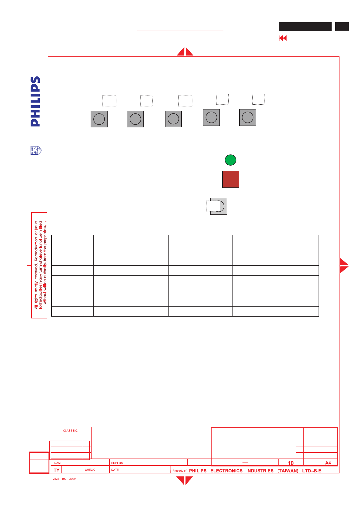
3.2.1 Keypad definition
Top:
B C D
Left Right Menu Down
Front :RCand powerswitch
E F
LED
IR
Up
ME5P 15" & 20"
Go to cover page
33
A
Power
switch
3.2.2 Key Function definition:
Key Function VGA modeTV/videomode
<A> Power Soft Power Soft Power
<B> Left Left/Volume down Left/Volume down
<C> Right Right/Volume up Right/Volume up
<D> Menu Call OSD menu Call OSD menu
<E> Down/channel down Down Down/Channel Down
<F> Up/Channelup Up Up/Channelup
PC modeAuto adjustment hot key:Press <B> and <C>atthe same time
and hold for 1 seconds.
1. Press “MENU”key to call main menu
2. By“Up/Down”to select function and “Left/Right”to adjust.
3. “Left/Right” also is VolumeHot Key
4.“Up/Down”also is
Channel Hot Key(TV mode)
5. Press hot Key<B>and<C> can auto-adjust picture position, phase
and clock in PC mode.
6. AV key is for switching input signal from PC/DVI/TV/AV/S-Video/HD.
2005-06-22
ISON KUO
20" ME5P TFT LCD TV
BRAND: PHILIPS
2005-06-22
24
590
7
Page 34
34
ME5P 15" & 20"
Go to cover page
4
GENERAL PRODUCT SPECIFICATION
Power LED:
Normal working:Green
Power saving:Red.
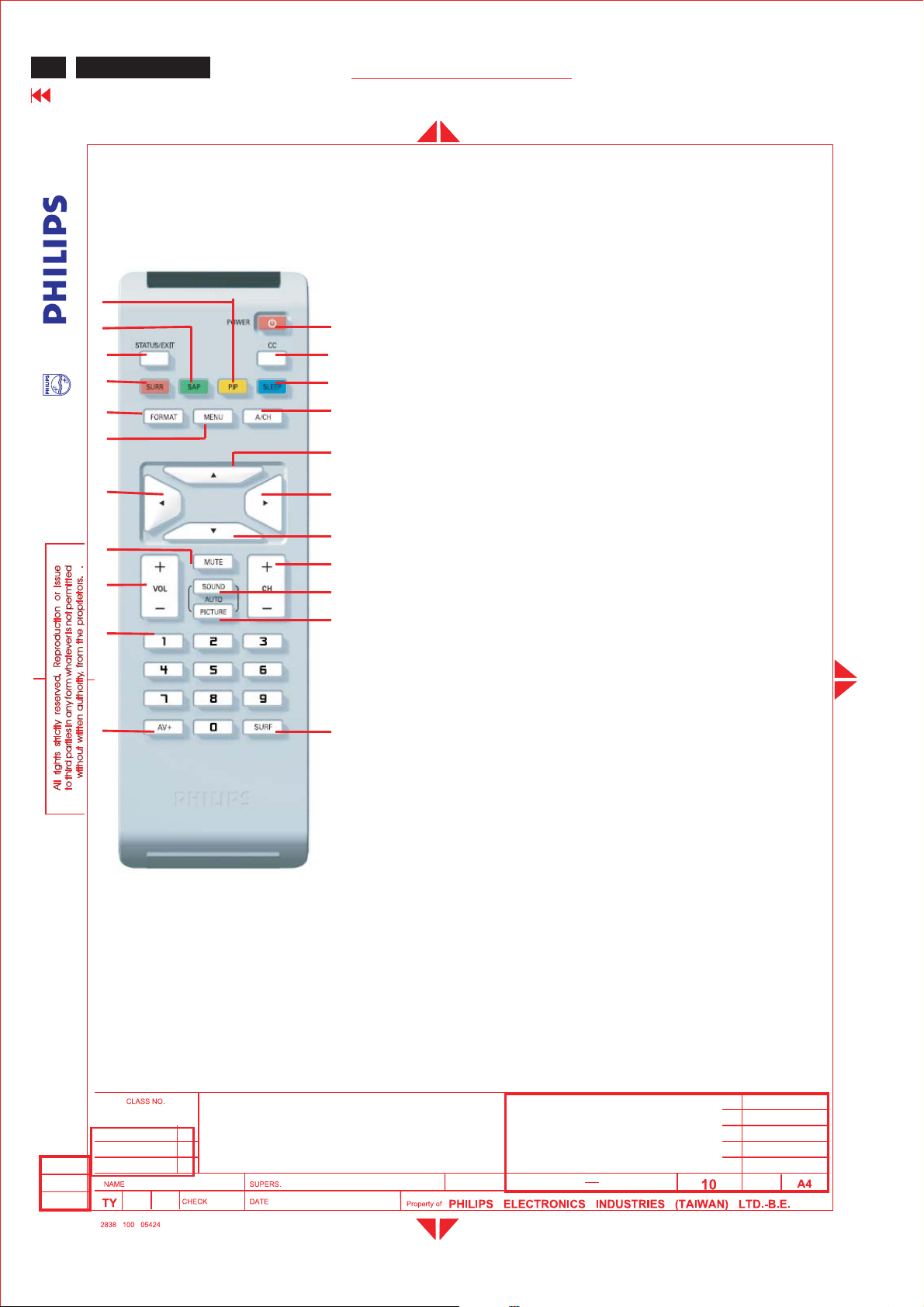
3.2.1Remote control
5
6
7
8
11
16
15
20
21
1
2
3
10
9
12
13
14
19
17
18
22
1.Power :Power On/Standby
2.Closed cap. :Closed caption on/off
3.Sleep Timer :Sleep timer
15,30,45,60,90,120,180,240,OFF
4.PIP : PIP size select (Small/Large/PBP)
5. SAP(2
6.States/Exit :Show states
7.Surround mode:Incrediable surround mode on/off
8.Format :Select display format
9. Menu :Mainmenuselect
10.ACH : Recall previous CH
11.Left key :OSDleft key
12.Upkey :OSDup key
13.Right key :OSDright key
14.Down key :OSDdown key
15.VOL+-:Volume Up/Down
16.Mute :Sound mute function
17.Smart Sound :Select sound effect
18.Smart Picture :Select picture effect
(Personal/Rich/Natural/Soft/Multimedia)
19.CH+-:Channel Up/Down
20. Number keys: (0~9) channel setting
21.AV+ :Select for PC,DVI,TV,AV,S-Video,HD
22.Surf :Setting favorite channel
nd
audio):Sound mode select
(4:3,Expand 4:3,Compress 16:9)
(Personal/Voice/Music/Theatre)
All PC or TV OSD menu function could be accomplished by remote control.
3.3 PC and TV requirement
3.3.1PCinterface
3.3.1.1Mode storing capacity
Pre-load :8
User modes :14
20" ME5P TFT LCD TV
2005-06-22
ISON KUO
BRAND: PHILIPS
2005-06-22
24
590
8
Page 35
Me5P 15" & 20"
GENERAL PRODUCT SPECIFICATION
3.3.1.2Horizontal scanning
Sync polarity :Positive or Negative
Scanning frequency : 30-40KHz
3.3.1.3 Vertical scanning
Sync polarity :Positive or Negative
Scanning frequency :56-62Hz
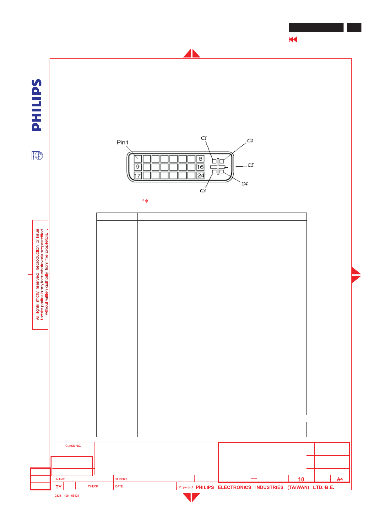
3.3.1.4Input connectors
Note the mark for DVI-I to Dsub only
ME5P 15" & 20"
Go to cover page
35
Pin No. Description
1TMDSdata2-
2TMDSdata2+
3 TMDS data2 shield
4NC
5NC
6 DDC clock
7 DDC data
8 * Analog V-sync
9TMDSdata1-
10 TMDS data1+
11 TMDS data1 shield
12 NC
13 NC
14 +5V
15 Ground(return for +5V and H/V-sync)
16 Hot plug detect
17 TMDS data0-
18 TMDS data0+
19 TMDS data0 shield
20 NC
21 NC
22 TMDS clock shield
23 TMDS clock+
24 TMDS clockC1
C2 * Analog G
C3 * Analog B
C4 * Analog H-sync
C5 * Analog GND (Analog R, G, B return)
* Analog R
2005-06-22
ISON KUO
20" ME5P TFT LCD TV
BRAND: PHILIPS
2005-06-22
24
590
9
Page 36
36
ME5P 15" & 20"
Go to cover page
GENERAL PRODUCT SPECIFICATION
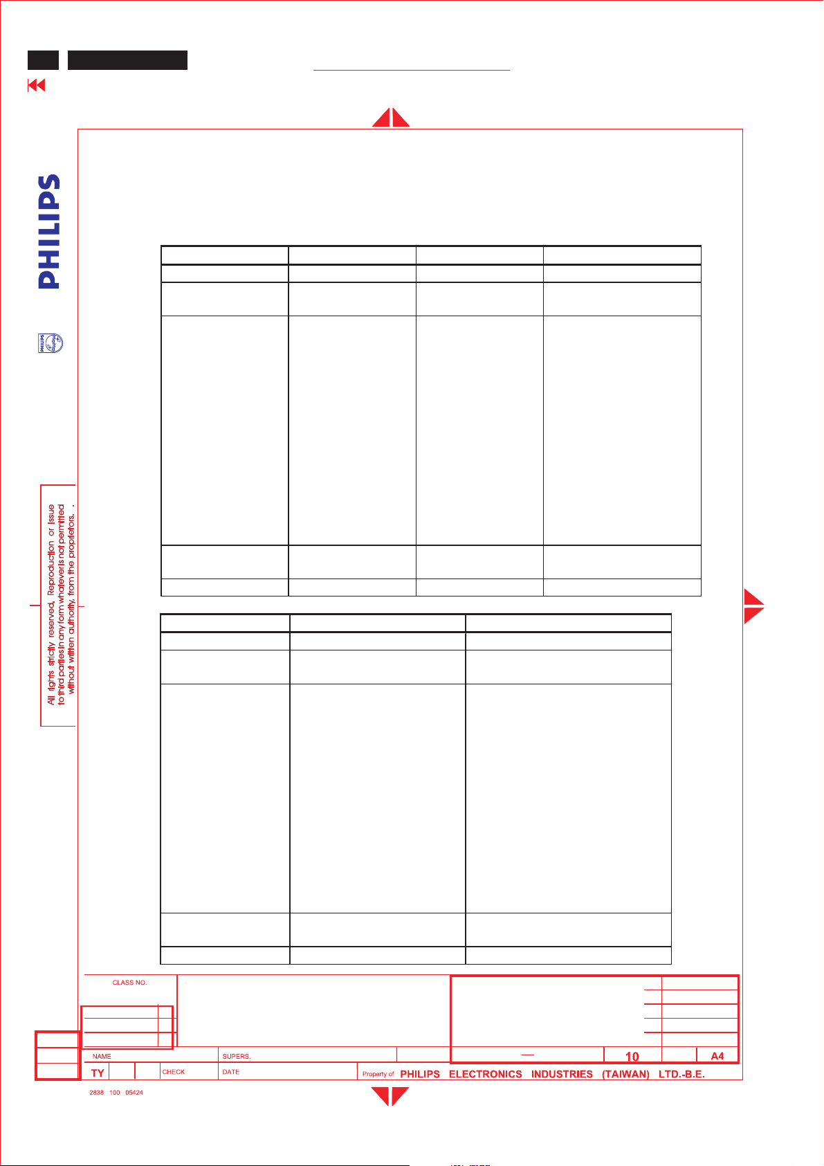
3.3.1.5Available timings
Factory pre-load timing, size and centering are according to the
reference timing charts. List as below
Mode 3, 6, 7 are preset modes that should pass QA inspection.
Mode 1, 2, 4, 5, 8 will run auto adjustment only, and W/O QA checking.
MODE NO. 12 3
RESOLUTION 640 x350 720 x 400 640 x 480
Dot clock(MHz) 25.17528.321 25.175
fh 31.469kHz31.469kHz31.469kHz
A (us) 31.78(800 dots) 31.78(900dots) 31.778 (800 dots)
B (us) 3.813(96 dots) 3.813(108dots) 3.813(96 dots)
C (us) 1.907(48 dots) 1.907(54dots) 1.907(48dots)
D (us) 25.42(640 dots) 25.42(720dots) 25.422 (640 dots)
E (us) 0.636(16 dots) 0.636(18dots) 0.636 ( 16 dots)
fv 70Hz(70.09)70Hz(70.087) 60Hz(59.940 )
O (ms ) 14.27(449 lines) 14.27(449 lines) 16.683 (525 lines )
P (ms) 0.064(2 lines) 0.064(2 lines) 0.064 ( 2 lines )
Q(ms) 1.875(59 lines) 1.080(34 lines) 1.049 ( 33 lines )
R (ms) 11.12(350 lines) 12.71(400 lines) 15.253(480 lines )
S (ms) 1.208(38 lines) 0.413(13 lines) 0.317(10 lines)
SYNC. H/V +/--/+ - / -
POLARITY
SEP . SYNC YY Y
MODE NO. 45
RESOLUTION 640x480 640 x 480
Dot clock(MHz) 30.240 31.500
fh 35.0kHz 37.500kHz
A (us) 28.571(864 dots) 26.667(840 dots)
B (us) 2.116( 64 dots) 2.032 ( 64 dots)
C (us) 3.175( 96 dots) 3.810 ( 120 dots)
D (us) 21.164(640 dots) 20.317(640 dots)
E (us) 2.116( 64 dots) 0.508( 16 dots)
fv 66.7 HZ( 66.667) 75Hz(75 )
O (ms ) 15.000(525 lines ) 13.333 (500 lines)
P (ms) 0.086(3lines) 0.080 ( 3 lines)
Q(ms) 1.114(39 lines ) 0.427(16 lines)
R (ms) 13.714(480 lines ) 12.80 (480 lines)
S (ms) 0.086(3lines) 0.027(1 line )
SYNC. H/V +/+ - / -
POLARITY Or -/-
SEP . SYNC YY
20" ME5P TFT LCD TV
2005-06-22
ISON KUO
BRAND: PHILIPS
2005-06-22
24
590
10
Page 37
Me5P 15" & 20"
GENERAL PRODUCT SPECIFICATION
ME5P 15" & 20"
Go to cover page
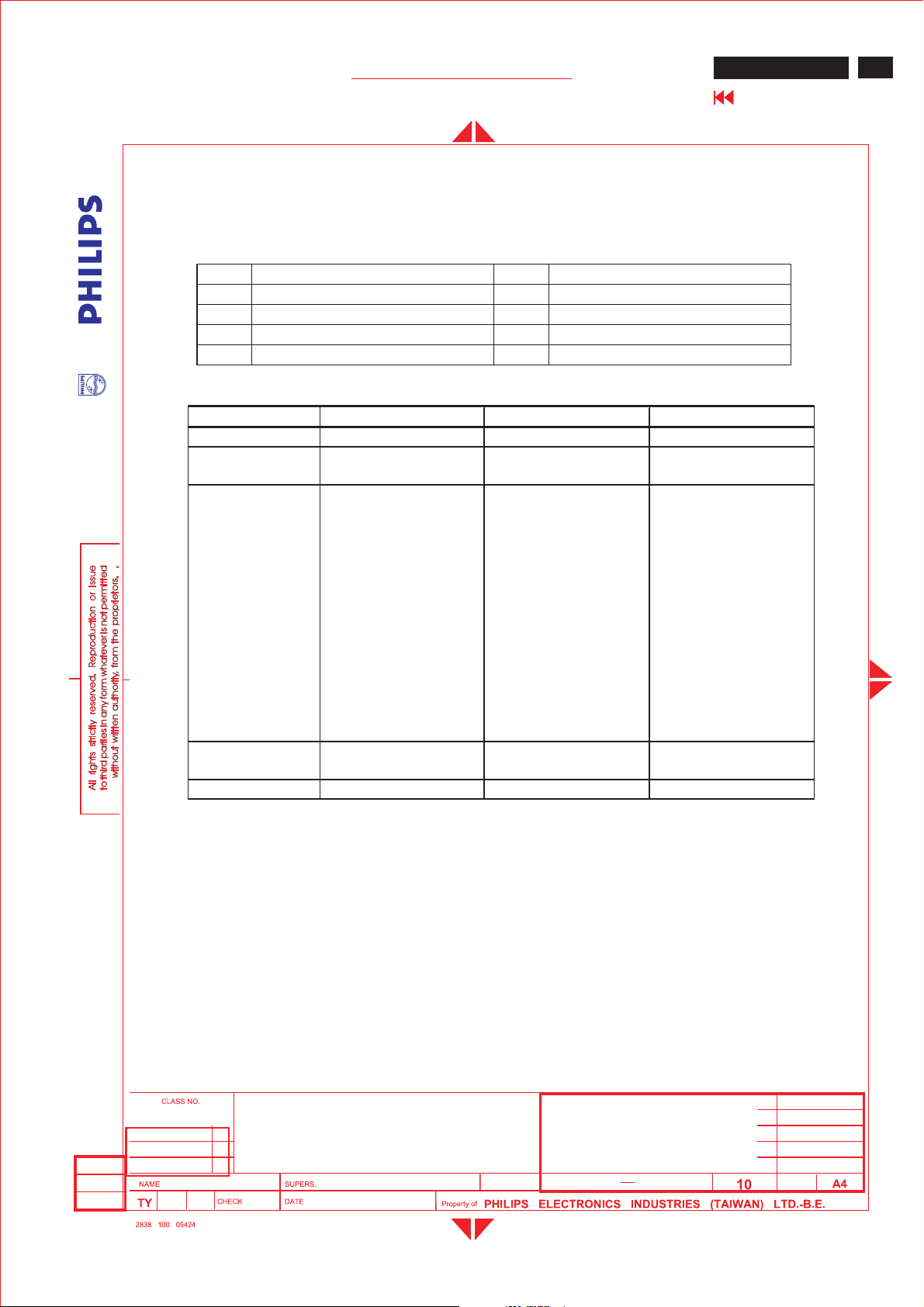
A : H-Total O:V-Total
B : H- Sync width P:V-Sync width
C : H- Back porch Q :.V- Back porch
D : H- Videowidth R:V-Videolength
E : H- Front porch S:.V- Front porch
MODE NO. 6 78
RESOLUTION 800 x 600 800 x 600 800 x 600
Dot clock(MHz) 36.000 40.000 49.500
fh 35.156kHz 37.879kHz 46.875kHz
A (us) 28.44 (1024 dots) 26.40 (1056 dots) 21.333 (1056dots)
B (us) 2.000 (72 dots) 3.200 ( 128 dots) 1.616 (80 dots)
C (us) 3.556 ( 128 dots) 2.200 ( 88 dots) 3.232 ( 160 dots)
D (us) 22.22 (800 dots) 20.00 (800 dots) 16.162 (800 dots)
E (us) 0.667( 24 dots) 1.000 ( 40 dots) 0.323( 16 dots)
37
fv 56Hz(56.25 ) 60Hz( 60.316)75Hz( 75.000)
O (ms ) 17.78 (625 lines) 16.58(628lines) 13.333 (625lines)
P (ms) 0.057(2 lines) 0.106 ( 4 lines) 0.064 (3lines)
Q(ms) 0.626 ( 22 lines) 0.607(23lines) 0.448(21 lines)
R (ms) 17.07(600 lines) 15.84 (600 lines) 12.80 (600lines)
S (ms) 0.028(1 line ) 0.026 ( 1 line ) 0.021 ( 1 line )
SYNC. H/V +/+ +/+ +/+
POLARITY
SEP . SYNC YYY
2005-06-22
ISON KUO
20" ME5P TFT LCD TV
BRAND: PHILIPS
2005-06-22
24
590
11
Page 38
38
ME5P 15" & 20"
Go to cover page
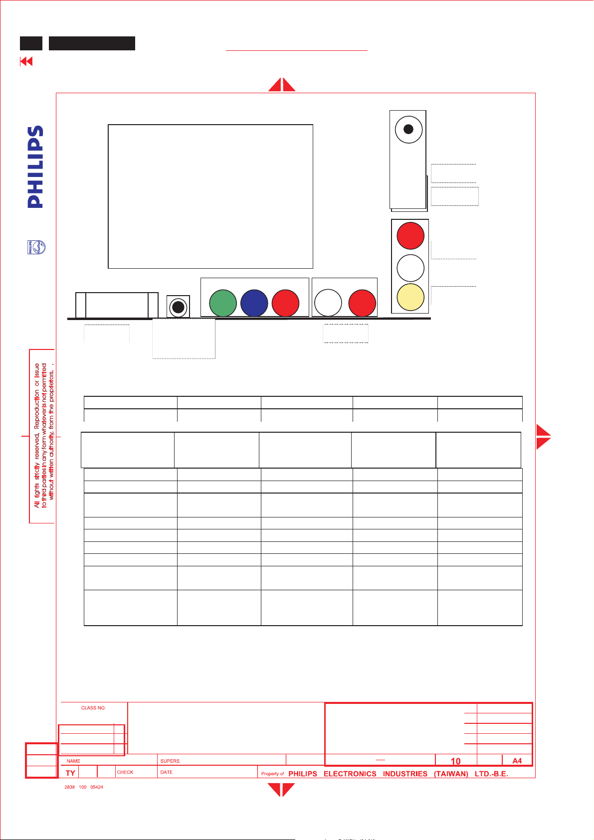
3.3.2TVinterface:
GENERAL PRODUCT SPECIFICATION
ME5P-20”TV function include
1. Tuner
2. S-video
3. CVBS (or AV)(RCA)
4.YPbPrand
audio(RCA)
5. Audio R/L input
(RCA)
6. DVI-Audio IN
-
Tuner
S-video
R
Audio
L
CVBS
DVI-
Audio IN
RL
Y
Pb
PrDVI-I
Audio
Following table is the deviation of main TV system.
Item W EUROPE America AP China
TV Color system PAL, SECAM NTSC PAL/NTSC, PAL
Tuner
TV system B/G, D/K, I , LM B/G , NTSC-M D/K
Sound decoder MSP3415G MSP3445G MSP3415G MSP3415G
CVBS,YC
Color system
Scaler MCU WE version NAFTA version AP version China version
Closed caption N Y NN
V-chip N Y NN
Teletext NN N N
Remote
controller(RC5)
Channel number 100 US Air 68, cable
FQ1216ME/I
Picture carrier
38.9MHz
Multi Multi Multi Multi
NAFTA version NAFTA version NAFTA version NAFTA version
FQ1236/F
Picture carrier
45.75MHz
125
FQ1216PN
Picture carrier
38.9MHz
100 100
FQ1256/IH-3
Picture carrier
38MHz
2005-06-22
ISON KUO
20" ME5P TFT LCD TV
BRAND: PHILIPS
2005-06-22
24
590
12
Page 39
Me5P 15" & 20"
GENERAL PRODUCT SPECIFICATION
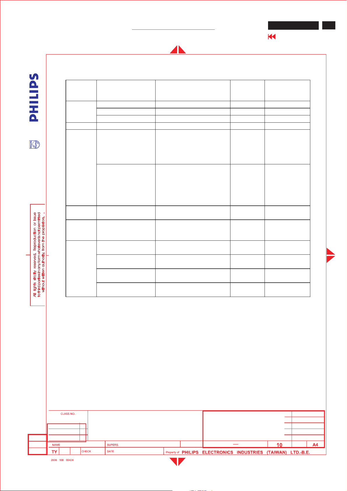
Following table is the detail TV System list.
TV
system
M
N4.5BTSC-stereo+SAP PAL Argentina
B/G
L6.5/5.85
I6.0/6.552
D/K
Position of sound
carrier
(MHz)
4.5/4.724212 FM-Stereo(A2) NTSC Korea
4.5FM-FM(EIA-J) NTSC Japan
4.5BTSC-stereo+SAP NTSC USA
5.5/5.7421875FM-stereo(A2) PAL
5.5/5.85
6.5/6.2578125
6.5/6.7421875
6.5/5.7421875
6.5/5.85
Sound system
FM-Mono/
NICAM
AM-Mono/
NICAM
FM-Mono/
NICAM
FM-Stereo
(A2,D/K1)
FM-Stereo
(A2,D/K2)
FM-Stereo
(A2,D/K3)
FM-Mono/
NICAM(D/K,NICAM)
Color
system
PAL
SECAM-L France
PAL
SECAMEast
PAL None
SECAMEast
PAL
ME5P 15" & 20"
Go to cover page
Country
Germany,
Austria,
Switzerland,
Italy,
Netherlands,
Belgium,
Spain,
Denmark,
Finland,
Norway,
Sweden.
Great Britain,
Hong Kong,
Ireland
Slovak. Rep.
Poland
China,
Hungary
39
3.3.2.1TVspecial setting:
CloseCaption, V-chip ( NAFTA Tuner,CVBS input source only)
20" ME5P TFT LCD TV
2005-06-22
ISON KUO
BRAND: PHILIPS
- CC-1 .. CC-4 decoding and display
-TXT1..TXT4 Text mode
-No Extended Data Services(EDS)
- support violence rating and checking
-Automatic CC-1 selectionatusermute
24
2005-06-22
590
13
Page 40
40
ME5P 15" & 20"
Go to cover page
GENERAL PRODUCT SPECIFICATION
3.3.3 Electric characteristics of I/O
DVI :
Analog (PC mode)
- Impedance: 75ohm .
-Level : 700mV
-Sync : TTL level, separate sync, + or - polarity
Digital interface with 4 channels TMDS signal
DVI-stereo input
-Audio:Impedance > 10 kohm . Input Level: 500 mVrms
(Speaker outpout 3W when Input level > 500mVrms and
Volume control at 100%)
RCA A/V, and audio R+L input
-Location:Rear side
- CVBS : 75ohm impedance.
DC coupled signals 1Vpp
(Sync:300mV, video:700mV)
-A
udio :Impedance > 10 kohm .
Input Level:500mVrms
(Speaker outpout 3W when Input level > 500mVrms and Volume
control at 100%)
- ESD-protected:15kV
Headphone
-Location :On scaler board.
-Peripherals :Headphones with impedance
between 8 – 600ohm
-Features :When headphone plug is
connected, loudspeaker
-Sound is muted.
-Volume control : with the loudspeaker volume.
-Connector type : 3.5 mm stereo Jack, with switch
-Specifications :-Output: 32ohm >10 mW
2005-06-22
ISON KUO
-Sound is the same as from the loudspeakers.
- ESD-protected :15kV
YPbPr:
-Location :Rear side
-Connector type :RCAJack
- Input : 75ohm .
S-video
:
-Location :Rear side
-Input : 75ohm .
20" ME5P TFT LCD TV
BRAND: PHILIPS
2005-06-22
24
590
14
Page 41
Me5P 15" & 20"
GENERAL PRODUCT SPECIFICATION
3.4Power input connection
AC/DC adapter : +16V DC/ 3.75A (AC input 100~240V)
Powercordlength :1.8 M
Powercordtype:3leads powercordwithprotectiveearth plug.
3.5Powermanagement
PC mode
The power consumption and the status indication of the set
with power management function are as follows,
STATUS Horizontal Vertical 120VAC230V
On PulsePulseTypical 55 W Green
Sleep No PulseNo Pulse < 1 W<1 W Red
Power switch off --< 1 W<1 W -
Power Spec
ME5P 15" & 20"
Go to cover page
AC
LED
41
TV mode
The power consumption and the status indication of the set
with power management function are as follows,
Power Spec
STATUS 120VAC230V
AC
LED
ActiveTypical 55 W Green
Sleep<1 W<1 W Red
Power switch off < 1 W<1 W -
In Monitor powersavingmode
, which no H&V sync, or absent either H-sync or V-
sync input via VGA connector. The monitor will enter“Monitor saving mode”. The way
to wake up or change source:
1.“Source”ke yonremote controlà change to TV source directly.
In TV powersavingmode
, which switched off by RC Standby”key, SLEEP
TIMER function or no TV signal input for 30 minutes, the monitor will enter“TV
standby mode”, a n d LED shows red color. The way to wake up:
1.”Source”ke yonremote controlà change to TV source directly.
2.”Standby”keyonremote control.
3.6Display identification
In accordance with DDC requirement – “DDC2B”.
20" ME5P TFT LCD TV
2005-06-22
ISON KUO
BRAND: PHILIPS
2005-06-22
24
590
15
Page 42
42
ME5P 15" & 20"
Go to cover page
GENERAL PRODUCT SPECIFICATION
4.0Visual characteristics
4.1Test conditions
Unless otherwise specified, this specification is defined under the
following conditions.
(1) Input signal :As defined in 3.3.1.2,800 x 600 non-interlaced
mode (37.9 KHz), signal sources must have 75 ohm output impedance.
(2) Luminance setting:Controls to be set to 450 Nits (typical) with full
screen 100 % duty cycle white signal.
(3)Warmup:More than 30 minutes after power on with signal supplied.
(4) Ambient light : 400 -- 600 lux.
(5) Ambient temperature:25+/-2 °C
4.2Resolution
Mode 3, 6, 7 are preset modes that should pass QA inspection.
Mode 1, 2, 4, 5, 8 will run auto adjustment only, and W/O QA checking.
# Resolution Frequency Pixel rate Sync Comment
1 640X350 31.5K/70HZ 25.175 (+/-) IBM VGA
2 720X400 31.5K/70HZ 28.322 (-/+) IBM VGA
3 640X480 31.5K/60HZ 25.175 (-/-) IBM VGA
4 640X480 35.0K/67HZ30.24 (-/-) MAC
5 640X480 37.5K/75HZ31.501 (-/-) VESA
6 800X600 35.2K/56HZ36 (+/+) VESA
7800X600 37.9K/60HZ 40 (+/+) VESA
8800X600 46.9K/75HZ 49.498 (+/+) VESA
4.3 Brightness:
Typical 450 nits at maximum contrast and Brightness. (at center of the
screen, Fig. 1 )
2005-06-22
ISON KUO
20" ME5P TFT LCD TV
BRAND: PHILIPS
2005-06-22
24
590
16
Page 43
Me5P 15" & 20"
GENERAL PRODUCT SPECIFICATION
4.5Brightness uniformity
Setcontrastat100% and turn the brightness to Max. (At original color)
Apply theFig 1, it should comply with the following formula:
Minimum luminance of five points (brightness)
Maximum luminance of five points (brightness)
4.6PCwhite color adjustment
There are three factory presetwhite color 8500K
Apply full white pattern, with brightness in 50 % position
and the contrast control at 50% position.
ME5P 15" & 20"
Go to cover page
> 75%
43
The1931CIEChromaticity (color triangle) diagram (x,y)
coordinate for the scree
ncenter should be:
8500K CIE coordinatesX=0.292 ± 0.030
Y=0.293 ± 0.030
4.7TVwhite color adjustment
There is one factory presetwhite color x=0.292 ± 0.030;y=0.293 ± 0.030
for TV RF signal with the1931CIEChromaticity diagram (x,ycoordinate
,FLUKE54200 color temp pattern, Smart picture is Personal.
4.8 TV
picture centering.
UseCVBS(PAL and NTSC) input with cross hatch pattern to check the
picture
centering and should be
Left(size)-right(size)<+/- 3mm.
Up(size)-down(size)<+/- 3mm.
2005-06-22
ISON KUO
20" ME5P TFT LCD TV
BRAND: PHILIPS
2005-06-22
24
590
17
Page 44
44
ME5P 15" & 20"
Go to cover page
GENERAL PRODUCT SPECIFICATION
6.0Mechanical characteristics
5.1Controls
Top Control :
-Upkey
-Down key
-Menu key
-Right key
-Left key
Front -RCsensor
-DCpower switch
Rear I/O:
-DCinlet
-PCD-sub
-DVI
-Tuner input
-Cinch CVBS input (AV)
-Cinch Audio input
(S-video and CVBS use same audio)
-S-Video input
-Mini jack PC audio input
- YPbPr,
-Audio for YPbPr
5.2Unit dimension / Weight
5.3 Tilt base
5.4Transportation packages
2005-06-22
ISON KUO
Set dimension (incl. pedestal): 506mm W x 484mm H x 218.6mm D
Net weight:8.5 Kg
tilt angle :0to 10
degree
5.4.1Shipping dimension/Weight
Carton dimension :547mm W x 222mm H x 549mm D
Gross weight :10.5 Kg
5.4.2Block unit / Palletization (Sea shipment)
layers/block
sets/layer sets/block unit
94 36
20" ME5P TFT LCD TV
BRAND: PHILIPS
24
2005-06-22
590
18
Page 45
6.0Environmental characteristics
The following sections define the interference and susceptibility
6.1Susceptibility of display to external environment
Operating
-Temperature:0to 35
-Humidity : 80%max
-Altitude:0-3658m
-Air pressure : 600-1100 mBAR
Storage
-Temperature:-20to 60
-Humidity :95%max(<40 )
-Altitude : 0-12192m
-Air pressure:300-1100 mBAR
45
Go to cover page
6.2Transportation tests
Stand
Height 49 and 25 cm
Drop Sequence followed, left, front, right, rear, top drop (25cm)
Test
Electrical function ok
Test Mechanical function ok
Result Noserious damage on set appearance
Sequence --- PACKAGING
Vibrati
Test Test Electrical function ok
Result Mechanical function ok
Noserious damage on set appearance
UAN-D1534/01
1
: bottom*3 , (60cm) drop
ISON KUO
Page 46
46
ME5P 15" & 20"
Go to cover page
GENERAL PRODUCT SPECIFICATION
6.3 Display disturbances from external environment
According to IEC 801-2 for ESD disturbances
7.0Reliability
7.1Mean time between failures
System MTBF (Excluding the LCD panel and CCFL) :50,000 hrs
CCFL MTBF : 50,000 hrs
8.0 Quality assurance requirements
8.1Acceptance test
according to MIL-STD-105D Control II level
AQL:0.65 (major) 2.5 (minor)
(please also refer to annual quality agreement)
9.0Serviceability
The serviceability of this monitor should fulfill the requirements which are
prescribed in UAW-0346 andmustbecheckedwiththechecklistUAT-0361.
Fig 1: Brightness and Uniformity measure points
H/10
b
a
1
V
3
a
b
H/2
5
H
9H
/10
2
4
b
a
V/
10
V/2
9V/
10
a
b
2005-06-22
ISON KUO
20" ME5P TFT LCD TV
BRAND: PHILIPS
2005-06-22
24
590
20
Page 47
Me5P 15" & 20"
GENERAL PRODUCT SPECIFICATION
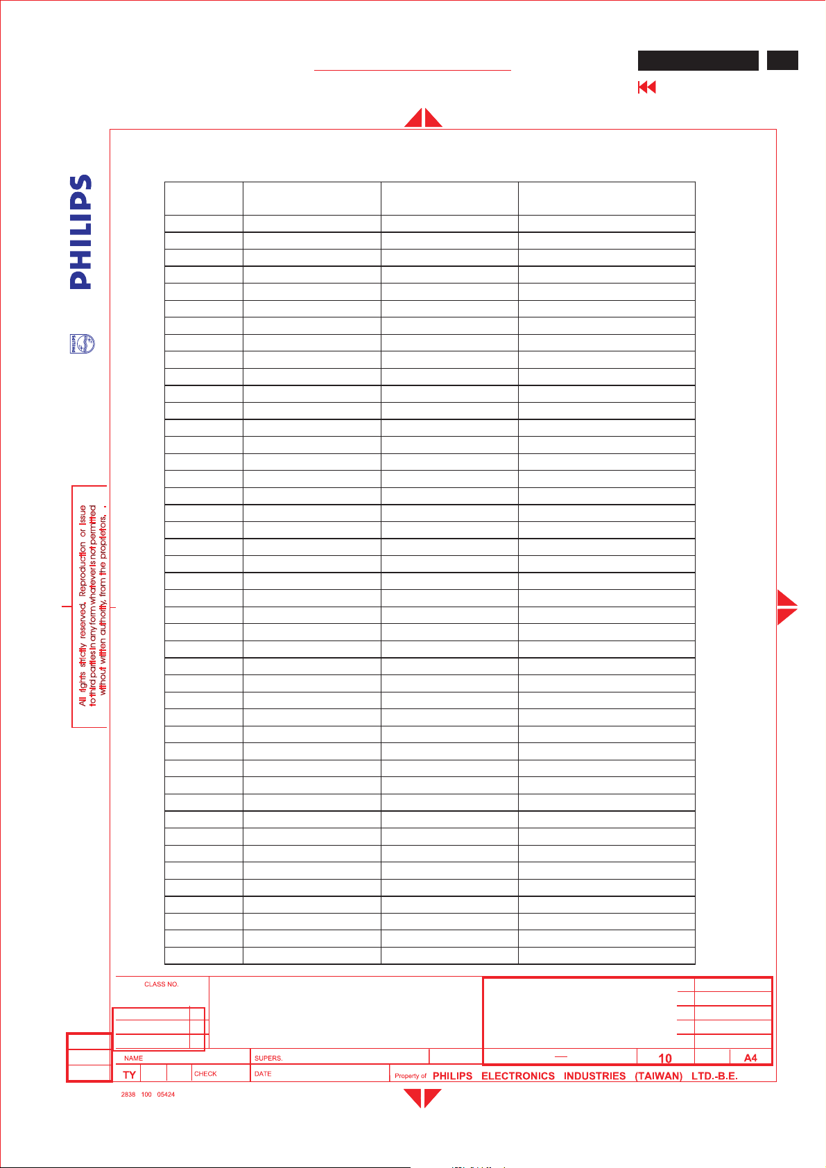
Table 1.NAFTA TV Channels
US- Air broadcast channel
Broadcast
Channel
255.25 59.75 54-60
3 61.25 65.75 60-66
467.25 71.75 66-72
5 77.25 81.75 76-82
6 83.25 87.75 82-88
7 175.25 179.75174-180
8 181.25 185.75180-186
9187.25 191.75186-192
10 193.25 197.75 192-198
11 199.25 203.75198-204
12 205.25 209.75 204-210
13 211.25 215.75 210-216
14 471.25 475.75470-476
15 477.25 481.75476-482
16 483.25 487.75482-488
17 489.25 493.75488-494
18 495.25 499.75 494-500
19 501.25 505.75 500-506
20 507.25 511.75 506-512
21 513.25 517.75 512-518
22 519.25 523.75518-524
23 525.25 529.75 524-530
24 531.25 535.75530-536
25 537.25 541.75536-542
26 543.25 547.75 542-548
27 549.25 553.75548-554
28 555.25 559.75 554-560
29 561.25 565.75 560-566
30567.25 571.75 566-572
31573.25 577.75572-578
32579.25 583.75578-584
33 585.25 589.75584-590
34 591.25 595.75 590-596
35597.25 601.75 596-602
36603.25 607.75 602-608
37 609.25 613.75608-614
38 615.25 619.75 614-620
39 621.25 625.75 620-626
40 627.25 631.75 626-632
41 633.25 637.75632-638
42 639.25 643.75638-644
43 645.25 649.75 644-650
44 651.25 655.75 650-656
45 657.25 661.75 656-662
Video Carrier(MHz) Audio Carrier
(MHz)
Range
(MHz)
ME5P 15" & 20"
Go to cover page
46
2005-06-22
ISON KUO
20" ME5P TFT LCD TV
BRAND: PHILIPS
2005-06-22
24
590
21
Page 48
48
ME5P 15" & 20"
Go to cover page
GENERAL PRODUCT SPECIFICATION
46 663.25 667.75 662-668
47 669.25 673.75668-674
48 675.25 679.75674-680
49 681.25 685.75680-686
50 687.25 691.75686-692
51 673.25 697.75 692-698
52 699.25 703.75698-704
53705.25 709.75 704-710
54 711.25 715.75 710-716
55 717.25 721.75 716-722
56 723.25 727.75 722-728
57729.25 733.75 728-734
58735.25 739.75 734-740
59 741.25 745.75 740-746
60 747.25 751.75 746-752
61 753.25 757.75 752-758
62 759.25 763.75 758-764
63765.25 769.75 764-770
64 771.25 775.75 770-776
65 777.25 781.75 776-782
66 783.25 787.75 782-788
67789.25 793.75 788-794
68795.25 799.75 794-800
69 801.25 805.75 800-806
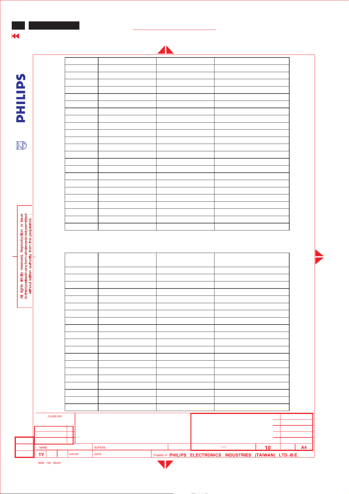
US-Cable channel
Cable
Channel
255.25 59.75 54-60
3 61.25 65.75 60-66
467.25 71.75 66-72
1 73.25 77.75 72-78
5 79.25 83.75 76-82
6 85.25 89.75 82-88
95 91.25 95.75 90-96
96 97.25 101.75 96-102
97 103.25 107.75 102-108
98 109.25 113.75108-114
99 115.25 119.75 114-120
14 121.25 125.75 120-126
15 127.25 131.75 126-132
16 133.25 137.75132-138
17 139.25 143.75138-144
18 145.25 149.75 144-150
19 151.25 155.75 150-156
20 157.25 161.75 156-162
21 163.25 167.75 162-168
22 169.25 173.75168-174
Video carrier
MHz
Audio carrier
MHz
Range
MHz
2005-06-22
ISON KUO
20" ME5P TFT LCD TV
BRAND: PHILIPS
2005-06-22
24
590
22
Page 49
Me5P 15" & 20"
GENERAL PRODUCT SPECIFICATION
7 175.25 179.75174-180
8 181.25 185.75180-186
9187.25 191.75186-192
10 193.25 197.75 192-198
11 199.25 203.75198-204
12 205.25 209.75 204-210
13 211.25 215.75 210-216
23 217.25 221.75 216-222
24 223.25 227.75 222-228
25 229.25 233.75228-234
26 235.25 239.75 234-240
27 241.25 245.75 240-246
28 247.25 251.75 246-252
29 253.25 257.75 252-258
30 259.25 263.75258-264
31 265.25 269.75 264-270
32 271.25 275.75270-276
33 277.25 281.75276-282
34 283.25 287.75282-288
35 289.25 293.75288-294
36 295.25 299.75 294-300
37 301.25 305.75 300-306
38 307.25 311.75 306-312
39 313.25 317.75 312-318
40 319.25 323.75318-324
41 325.25 329.75 324-330
42 331.25 335.75 330-336
43 337.25 341.75 336-342
44 343.25 347.75 342-348
45 349.25 353.75348-354
46 355.25 359.75 354-360
47 361.25 365.75 360-366
48 367.25 371.75 366-372
49 373.25 377.75372-378
50 379.25 383.75378-384
51 385.25 389.75384-390
52 391.25 395.75 390-396
53 397.25 401.75 396-402
54 403.25 407.75 402-408
55 409.25 413.75408-414
56 415.25 419.75 414-420
57 421.25 425.75 420-426
58 427.25 431.75 426-432
59 433.25 437.75 432-438
60 439.25 443.75438-444
61 445.25 449.75 444-450
62 451.25 455.75 450-456
63 457.25 461.75 456-462
ME5P 15" & 20"
Go to cover page
49
2005-06-22
ISON KUO
20" ME5P TFT LCD TV
BRAND: PHILIPS
2005-06-22
24
590
23
Page 50
50
ME5P 15" & 20"
Go to cover page
GENERAL PRODUCT SPECIFICATION
64 463.25 467.75 462-468
65 469.25 473.75468-474
66 475.25 479.25 474-480
67 481.25 485.75480-486
68 487.25 491.75486-492
69 493.25 497.75 492-498
70 499.25 503.75498-504
71 505.25 509.75 504-510
72 511.25 515.75 510-516
73 517.25 521.75 516-522
74523.25 527.75 522-528
75 529.25 533.75528-534
76535.25 539.75534-540
77 541.25 545.75 540-546
78 547.25 551.75 546-552
79553.25 557.75 552-558
80 559.25 563.75558-564
81 565.25 569.75 564-570
82571.25 575.75570-576
83 577.25 581.75576-582
84583.25 587.75582-588
85589.25 593.75588-594
86 595.25 599.75 594-600
87 601.25 605.75 600-606
88 607.25 611.75 606-612
89613.25 617.75 612-618
90 619.25 623.75618-624
91 625.25 629.75 624-630
92 631.25 635.75630-636
93 637.25 641.75636-642
94 643.25 647.75 642-648
100 649.25 653.75648-654
101 655.25 659.75 654-660
102 661.25 665.75 660-666
103 667.25 671.75 666-672
104 673.25 677.75672-678
105 679.25 683.75678-684
106 685.25 689.75684-690
107 691.25 695.75 690-696
108 697.25 701.75 696-702
109 703.25 707.75 702-708
110 709.25 713.75 708-714
111 715.25 719.75 714-720
112 721.25 725.75 720-726
113727.25 731.75 726-732
114 733.25 737.75 732-738
115 739.25 743.75 738-744
116 745.25 749.75 744-750
117751.25 755.75 750-756
118757.25 761.75 756-762
119 763.25 767.75 762-768
120 769.25 773.75 768-774
121 775.25 779.75 774-780
122 781.25 785.75 780-786
123 787.25 791.75 786-792
124 793.25 797.75 792-798
125 799.25 803.75 798-804
2005-06-22
ISON KUO
20" ME5P TFT LCD TV
BRAND: PHILIPS
2005-06-22
24
590
24
Page 51
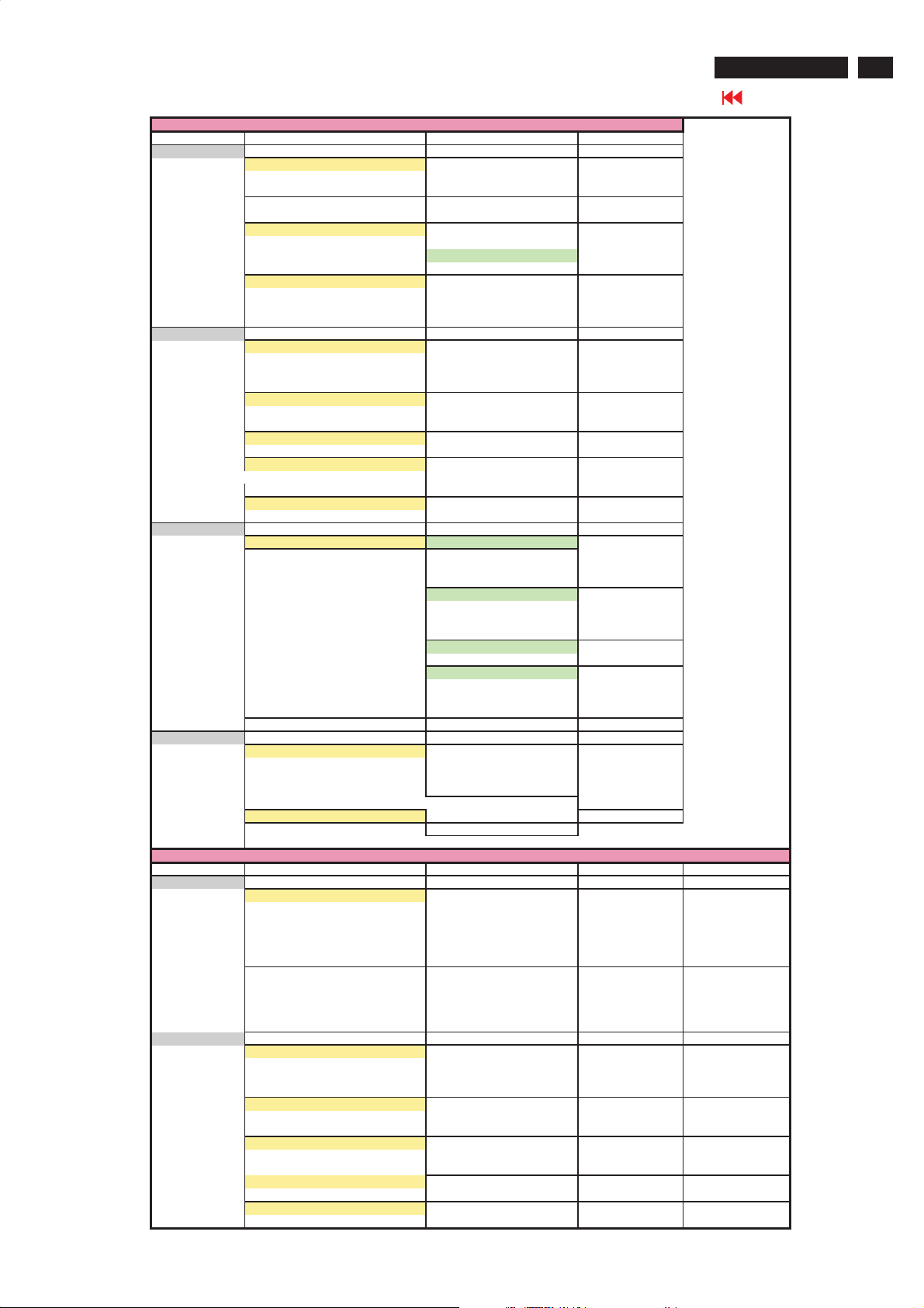
On Screen Display
PC MODE
1st Layer 2nd Layer 3rd Layer
PICTURE
COLOR TEMP NORMAL
WARM
COOL
BRIGHTNESS
CONTRAST
AUTO ADJ UST YES
IN PROGRESS
STORE? YES
NO
MANUAL ADJUST P HASE
CLOCK
HORIZONTAL
VERTICAL
AUDIO
AUTO SOUND PERSONAL
VOICE
MUSIC
THEATRE
SETTINGS TREBLE
BASS
BALANCE
STEREO
INCREDIBLE SURROUND INCREDIBLE SURROUND
OFF
AVL OFF
ON
FEATURES
PIP SIZE OFF
SMALL
LARGE
PBP
VIDEO TV
AV
S-VIDEO
COMPONENT
AUDIO PC
PIP
DISPLAY ICON1
ICON2
ICON3
ICON4
INSTALL
LANGUAGE ENGLISH
FRANÇAIS
ESPAÑOL
PORTUGUÊS
FACTORY RESET NO
YES
DVI/TV / AV/ S-VIDEO / HDTV MODE
1st Layer 2nd Layer 3rd Layer 4th Layer 5th Layer
PICTURE
AUTO PICTURE PERSONAL
RICH
NATURAL
SOFT
MULTIM EDIA
BRIGHTNESS
COLOR
CONTRAST
SHARPNESS
TINT
AUDIO
AUTO SOUND PERSONAL
VOICE
MUSIC
THEATRE
SETTINGS TREBLE
BASS
BALANCE
STEREO STEREO
SAP
MONO
INCREDIBLE SURROUND INCREDIBLE SURROUND
OFF
AVL OFF
ON
ME5P 15" & 20"
Go to cover page
51
Page 52
52
ME5P 15" & 20"
Go to cover page
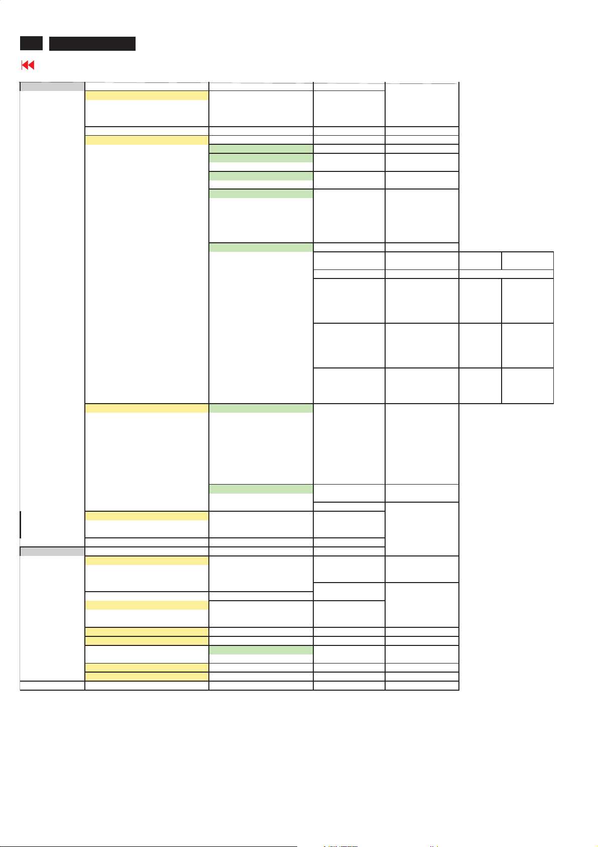
On Screen Display
FEATURES
PICTURE FORMAT 4:3 (4:3)
EXPAND 4:3 (HD 4:3)
COMPRESS 16:9
PICTURE ALIGNMENT
AUTO LOCK LOCK PROGRAM
CHANGE CODE YES
CLEAR ALL ON
OFF
BLOCK OPTION ON
OFF
MOVIE RATING G ON/OFF
PG ON/OFF
PG13 ON/OFF
R ON/OFF
NC17 ON/OFF
X ON/OFF
TV RATING TV Y ON/OFF
TV Y7 BLOCK ON/OFF
FV ON/OFF
TV G ON/OFF
TV PG BLOCK ON/OFF
V ON/OFF
S ON/OFF
L ON/OFF
D ON/OFF
TV 14 BLOCK ON/OFF
V ON/OFF
S ON/OFF
L ON/OFF
D ON/OFF
TV MA BLOCK ON/OFF
V ON/OFF
S ON/OFF
L ON/OFF
CLOSED CAPTION CAPTION MODE CC1
CC2
CC3
CC4
TXT1
TXT2
TXT3
TXT4
CC MUTE
CC DISPLAY ON
OFF
INSTALL
COLOR TEMP NORMAL
LANGUAGE ENGLISH
TUNER MODE
AUTO PROGRAM START?
CHANNEL EDIT CHANNEL
MANUAL FINE TUNE
FACTORY RESET NO
WARM
COOL
FRANÇAIS
ESPAÑOL
PORTUGUÊS
ATENNA
CABLE
AUTO
SKIPPED ACTIVE
YES
SKIPPED
Page 53
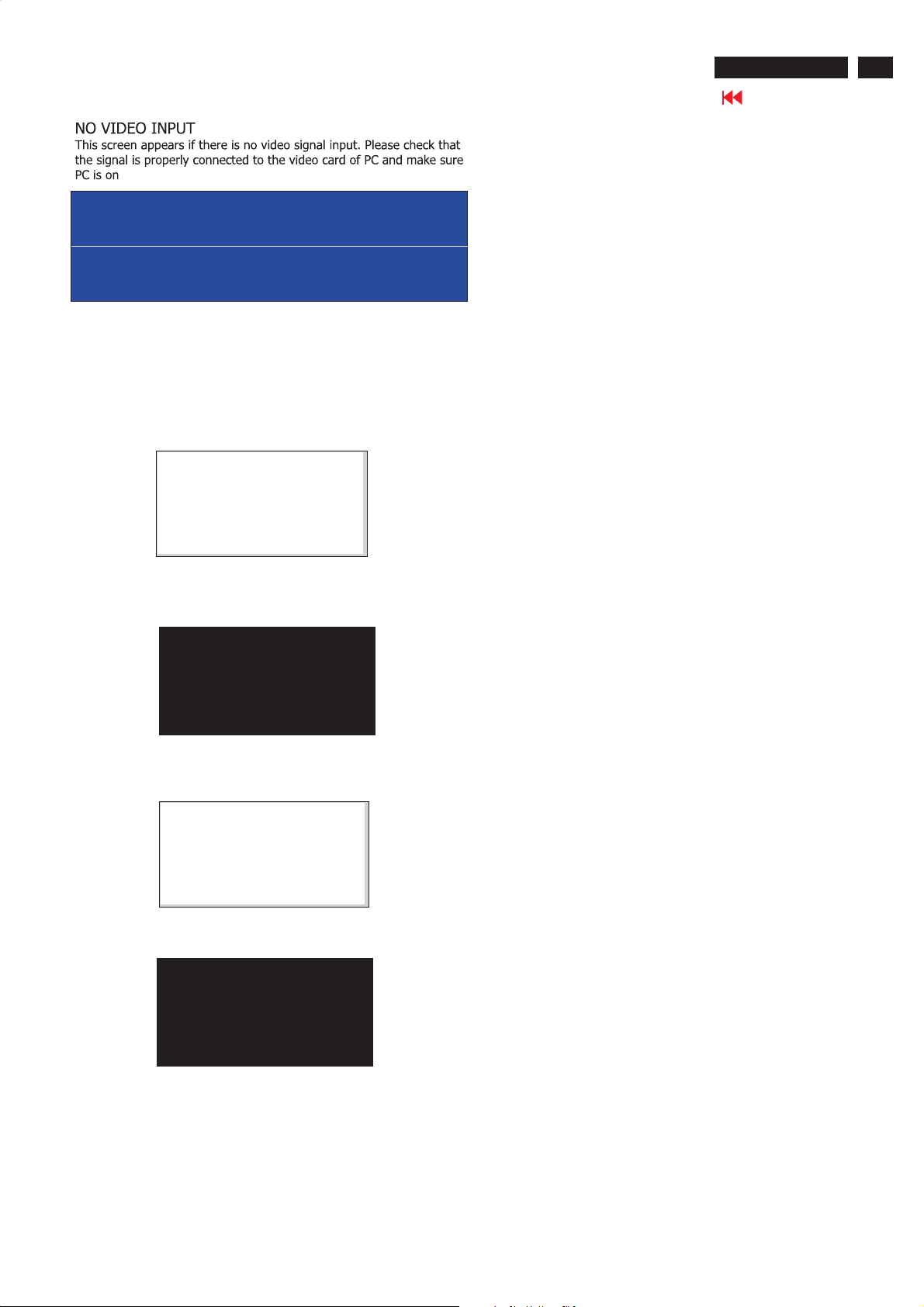
Aging Mode
ATTENTION
NO VIDEOINPUT
Access Aging.. Mode
Step 1 :Select the source"PC" and then turnoff LCD-TV, and disconnect
Interface Cable between Monitorand PC.
Step 2 :[Push "power " button and then push the"VOL- " and "VOL+"
buttonsatthe same timeimmediately and holdit] untill comes
"AGING screen" then release all buttons.
Bring up:
AGING...
out
ME5P 15" & 20"
Go to cover page
53
After 55 seconds, bring up:
After 5 seconds, bring up:
After 55 seconds, bring up:
AGING...
----------
---------repeatly
Connect Signal cable again=> go back tonormal display
Page 54

54
ME5P 15" & 20"
Warning Message
Go to cover page
1.Automatic adjustment (for factory only)
Press Volume+ and Volume- on front key at the same time (PC mode
only). It adjusts PC image to the best and save the screen automatically.
2. OUT OF RANGE
If PC input timing is out of range, it shows OUT OF RANGE warning
message on the center of the screen. The range of horizontal frequency
is between 14 - 63 KHz. The range of vertical frequency is between
45 - 76 Hz. The OSD won t timeout.
3.NO VIDEO INPUT
When PC input timing has either horizontal frequency or vertical
frequency. Or neither has horizontal frequency nor vertical frequency.
It shows on the center of the screen for 30 seconds, then it will enter
sleep mode.
'
""
Page 55
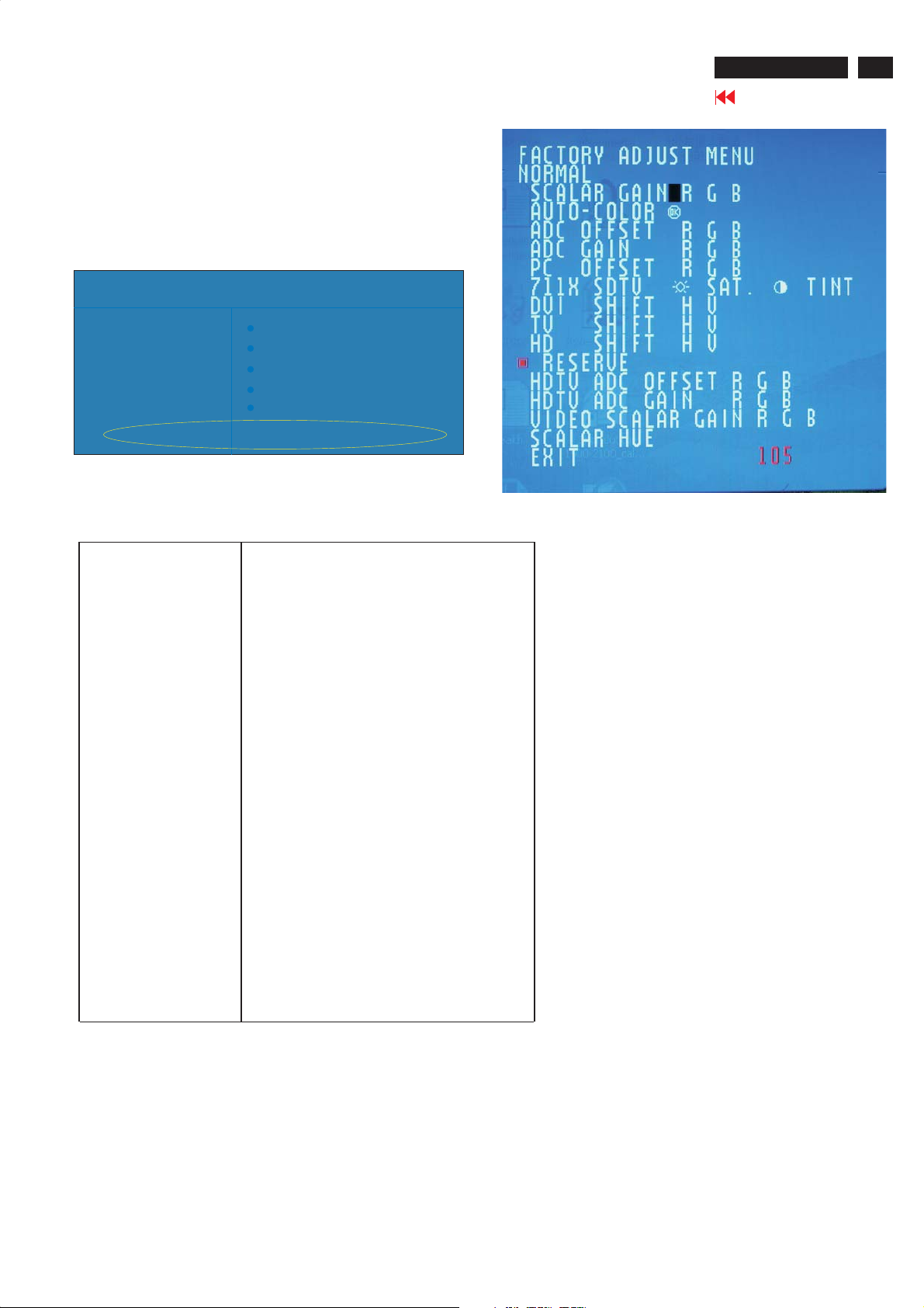
Factory Mode
Access factory. Mode
how to get into factory mode menu
Step 1 :Select the source "PC"andthen turn off LCD-TV.
Step 2 :[Push "power " button andthen push the"VOL- "and"VOL+"
buttons at the sametime immediatelyand hold it] about five seconds
then releaseall buttons.
Press "menu"button and bring up factory mode indication asshown in
Fig.1
ME5P 15" & 20"
Go to cover page
55
MAIN CONTROLS
PICTURE
800X600@60HZ
SMART PICTURE
AUDIO BRIGHTNESS
FEATURES CONTRAST
INSTALL AUTO ADJUST
MANUAL ADJUST
ME5P NAFTA20 V0.45.1 050527AU20SVGA
Fig.1
Usethe CHNNEL- and CHNNEL+ to select the"ME5PNAFTA20
V0.45.1 050527AU20SVGA"andthenpre
ss the"VOL +" button
Menu ItemDescription
Scalar GainRGB Scalar Gain for Normal/Warm/CoolinPCmode.
Auto-Color
ADC Offset RGB Adjust AD 9883 for PCADCoffset.
ADC GainRGB Adjust AD 9883for PCADCgain.
PCOffset RGB PC analogscalar offset.
711X SDTV Brightness Adjust SA 7119 SDTV brightness.
Adjustcolor from received signal (either in PC or
HDTV mode).
711X SDTVSAT.
711X SDTV Contrast Adjust SA 711 9 SDTV contrast.
711X SDTV TINT Adjust SA 7119 SDTV tint(hue).
TV Shift HV Adjust TV screenpositionhorizontally/vertically.
HD Shift HV
ShowLock Message Show OSD lock message.
HDTV ADC Offset RGB Adjust AD 9883 for HDTV ADC offset.
HDTV ADC GainRGB Adjust AD 9883 for HDTV ADC gain.
Video Scalar GainRGB Adjust scalar gain for Video mode.
Scalar Hue Adjust scalar hue.
Adjust SA 711 9 SDTV saturation.
Adjust HDTV screenposition
horizon tally/vertically.
Page 56

56
ME5P 15" & 20"
Trouble shooting
Go to cover page
No Power
.Check the TV power cord. Disconnect the power cord from the
power outlet for 10 seconds, then reinsert the plug into the outlet.
Press POWER to turn on the TV again.
.Make sure the outlet is not on a wall switch.
.Make sure a fuse has not blown at the power outlet.
No Pi c ture
.Check the antenna or Cable TV connections. Connect the antenna or
Cable TV signal securely to the TV’s 75ohm jack on the rear of the TV.
.Set TUNER MODE correctly. Details are on page 15.
.Activate AUTO PROGRAM to find all available channels.
In case you hear only sound and don’t see any picture in S-Video or
Video (CVBS) mode. Please check if you have connected Video signal
to S-Video or Video (CVBS) input. Only one of the two video inputs can
be connected to sound. This means that the same sound can be heared
in S-Video and Video (CVBS) mode.
No Sound
.Press the VOL+ and VOL- buttons to adjust the volume.
.Press the MUTE button on the remote control to cancel or restore the
volume.
.If you have connected other equipment to the TV (such as a VCR or
DVD Player), make sure the audio cables are connected securely
between the TV and the other equipment.
.Check the SOUND settings.
.In case you hear wrong sound in S-Video or Video (CVBS) mode.
Please check if you have connected the right sound signal to AV in
(S-Video or Video input). Only one of the two video inputs can be
connected to sound, but both video signals can be connected.
This means that only one of the two sound inputs can be heared in
S-Video and Video (CVBS) mode.
Remote Control does not work.
.Check the batteries. If necessary, replace them with two AAA heavy
duty (zinc chloride) or alkaline batteries.
.Clean the remote control as well as the remote control sensor on the
front of the TV.
.Check the TV power cord. Disconnect the power cord from the power
outlet for 10 seconds, then reinsert the plug into the outlet. Press POWER
to turn on the TV again.
.Make sure the outlet is not on a wall switch.
.Make sure a fuse has not blown at the power outlet.
.Always point the remote control toward the front of the TV (toward the
remote sensor).
.Make sure that you use the supplied Magnavox Remote control, only the
supplied Magnavox Remote control can be used with this LCD-TV set.
TV displays wrong channel or no channels.
.Repeat channel selection.
.Add the channel number(s) into the TV’s memory. Use STORE.
.Make sure TUNER MODE is set correctly.
Then activate AUTO PROGRAM to set up all available channels.
Page 57
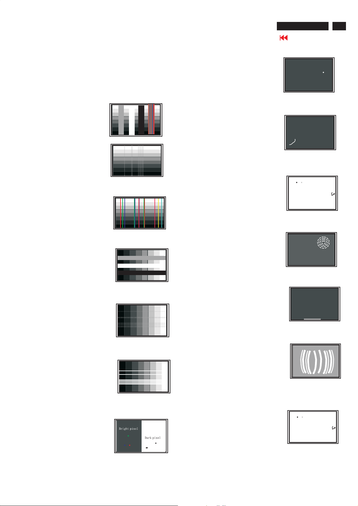
Failure Mode Of Panel
Quick reference for failure mode of LCD panel
this page presents problems that could be made by LCD panel.
It is not necessary to repair circuit board. Simply follow the mechanical
instruction on this manual to eliminate failure by replace LCD panel.
Polarizer has bubbles
ME5P 15" & 20"
Go to cover page
57
Failure description
Vertical block defect
Vertical dim lines
Vertical lines defect
(Always bright or dark)
Horizontal block defect
Phenomenon
Polarizer has bubbles
Foreign material inside
polarizer. It shows liner or
dot shape.
Concentric circle formed
Horizontal dim lines
Horizontal lines defect
(Always bright or dark)
Has bright or dark pixel
Bottom back light of LCD is
brighter than normal
Back light un-uniformity
Backlight has foreign material.
Black or white color, liner or
circular type
Page 58
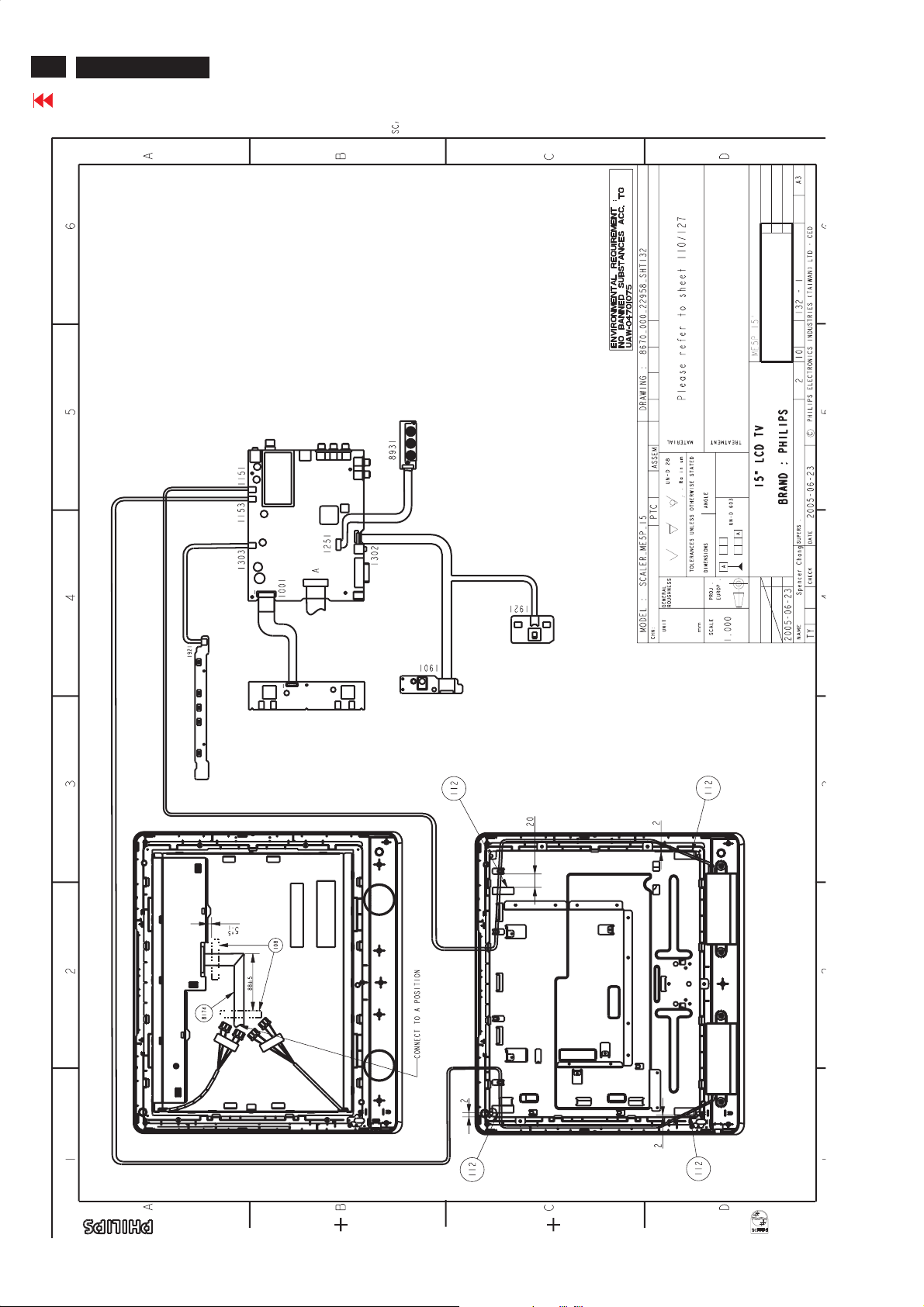
58
ME5P 15" & 20"
Go to cover page
Wiring diagram
Page 59
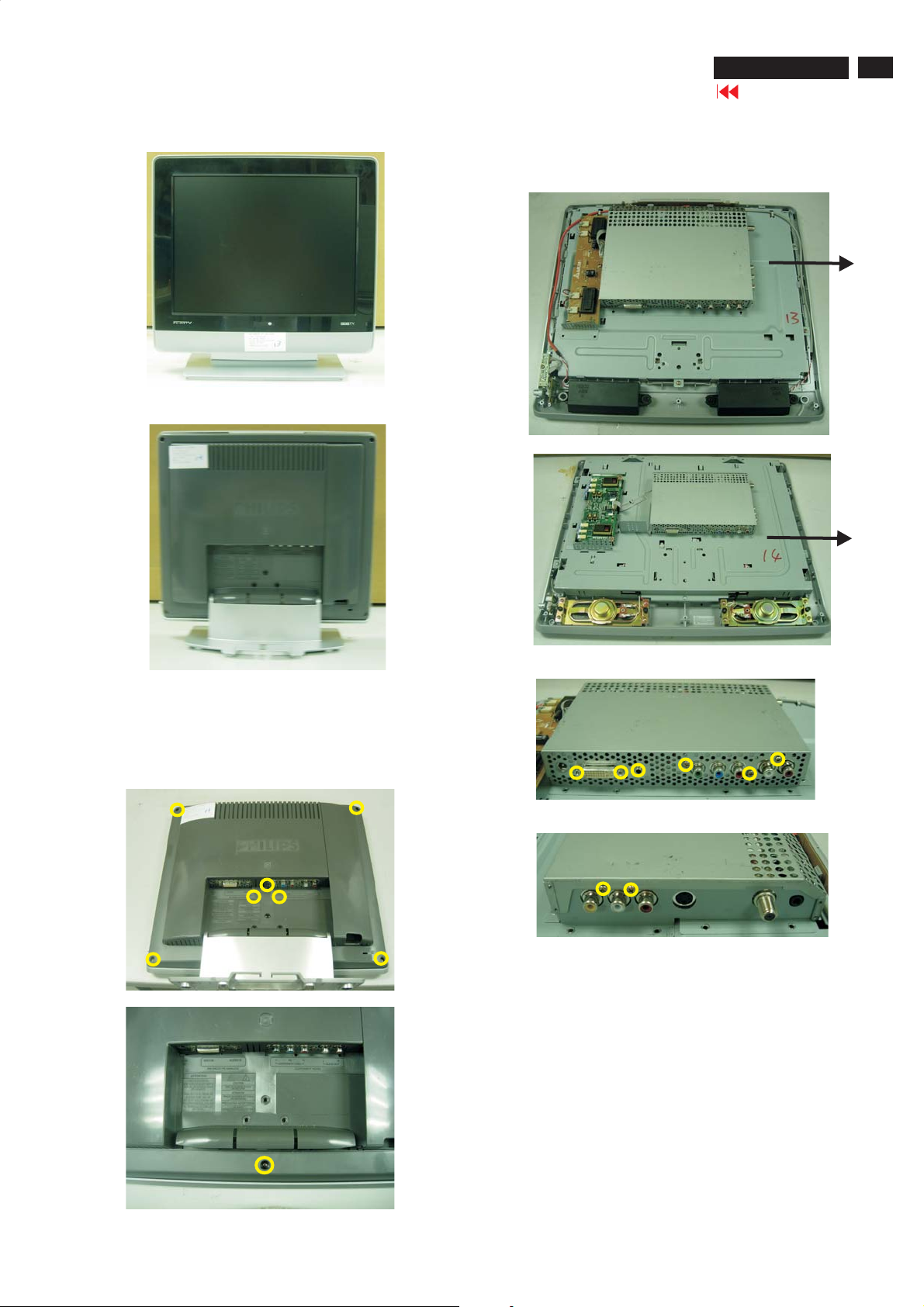
Mechanical Instructions
ME5P 15" & 20"
Go to cover page
59
Front View
Back View
4. Remove the metal frame board
- Remove the screws as shown in Fig.7 and Fig.8
- Remove the metal frame board
For 15"
Fig.1
Fig.5
For 20"
1. Remove the base & back cover
- Remove the three screws 1,2,3 as shown in Fig.3,
then remove the base.
- Remove the other screws as shown in Fig.3 and Fig.4,
then remove the back cover
2
1
3
Fig.6
Fig.2
Fig.7
Fig.8
Fig.3
Fig.4
Page 60
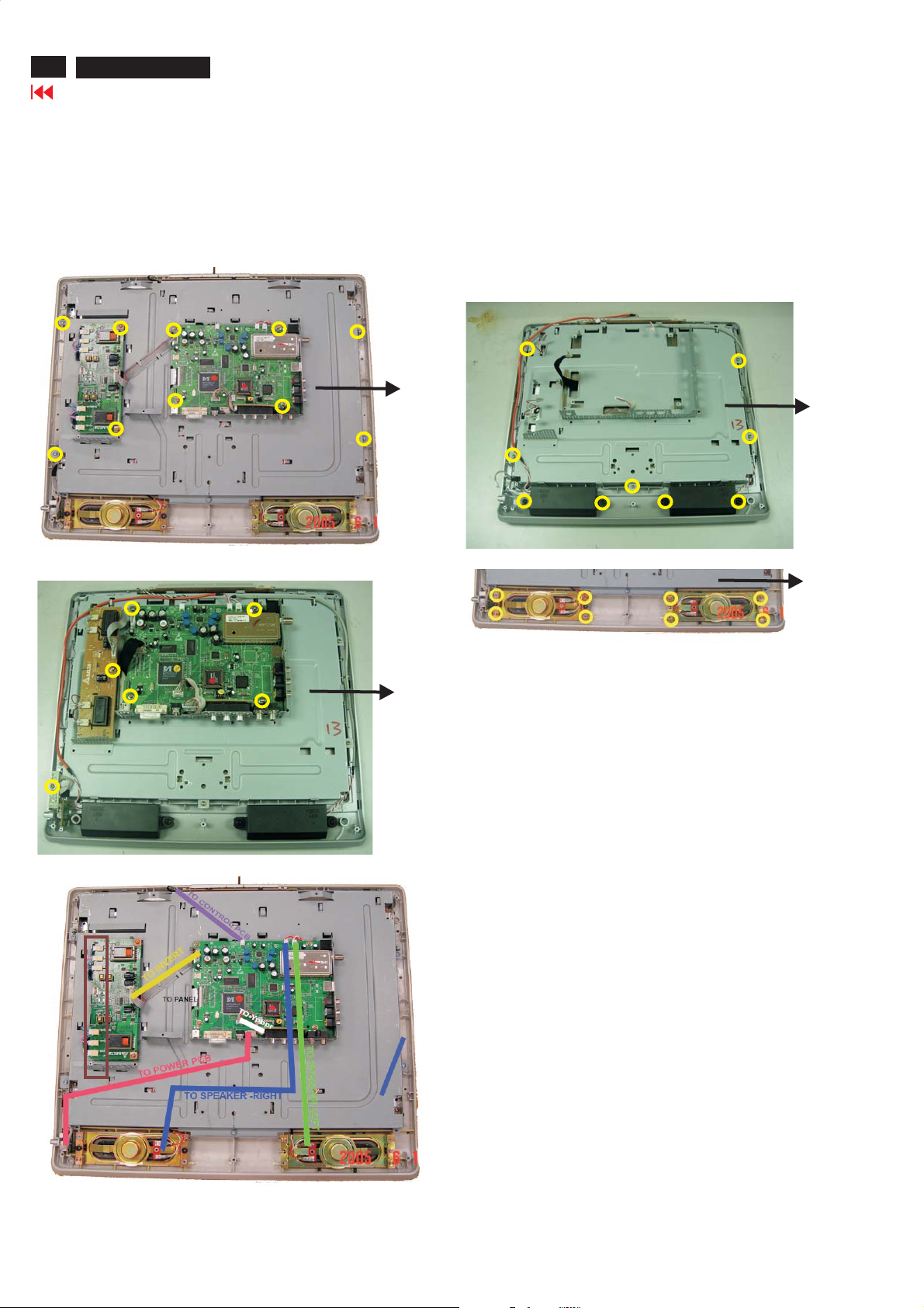
60
ME5P 15" & 20"
Go to cover page
5. Remove all PCB
- Remove all screws as shown in Fig.9 and Fig.10
- Unplug all connector as shown in Fig.11
Mechanical Instructions
6. Remove the speaker
- Remove the screws on the speakers as shown in Fig.12 and Fig.13,
then remove the speakers from the bezel
7. Remove the panel
- Remove the five screws(1,2,3,4,5) as shown in Fig.12,then remove
the panel from the front bezel
For 20"
Fig.9
For 15"
3
1
2
For 15"
5
4
Fig.12
For 20"
Fig.13
Backlight Connector
Fig.10
Fig.11
Page 61
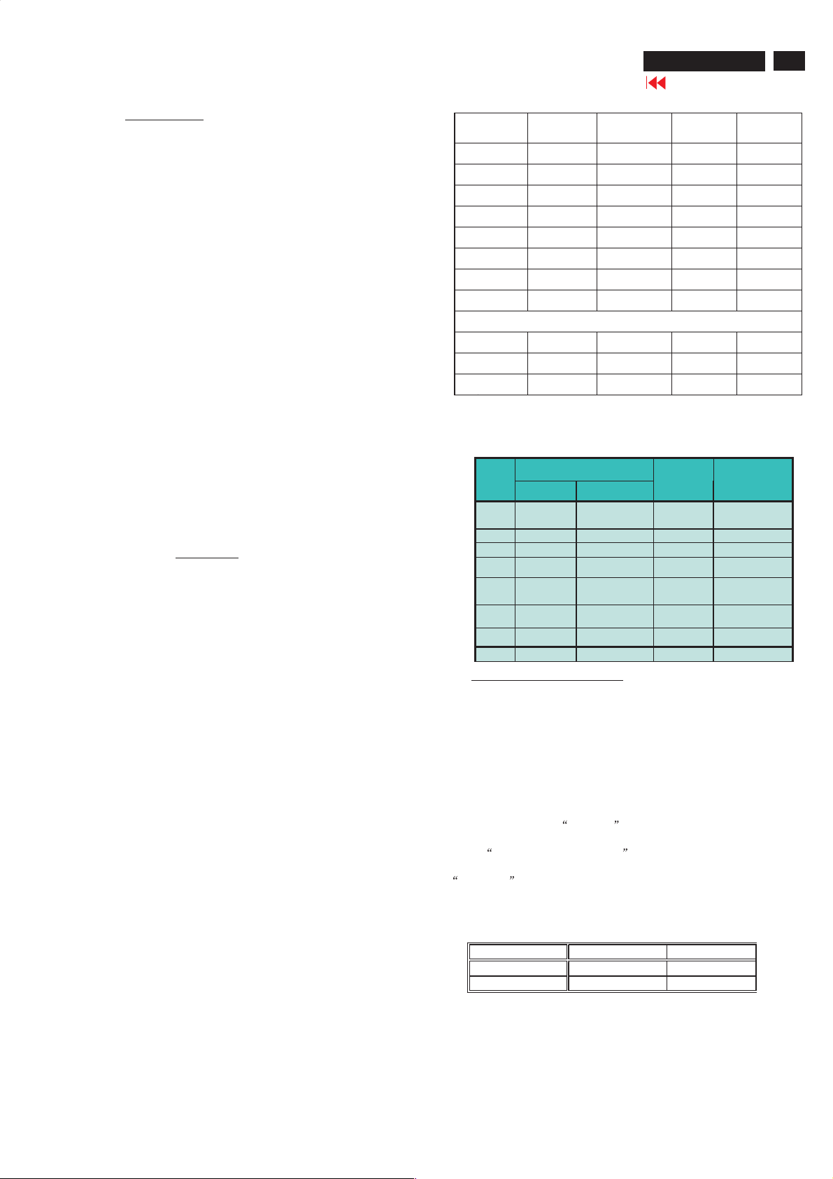
Electrical Instructions
ME5P 15" & 20"
Go to cover page
61
1. General points
1.1 During thetestandmeasuring, supply a distortion free AC
mains voltage to the apparatus via an isolated transformer with low
internal resistance.
1.2 All measurements mentionedhereafter are carried out at
a normal mains voltage (90 - 132 VAC for USA version, 195 -264
VAC for EUROPEAN version, or 90 - 264 VAC for the model withfull
range power supply, unless otherwise stated.)
1.3 All voltages are to be measurement or appliedwith respect to
ground, unless ot
1.4 Thetesthas to be done on a complete set including LCD
panel in a roomwith temperature of25+/-5degree C.
1.5 All values men tioned in these test instruction are only
applicable of a well aligned apparatus,with correct signal.
1.6 Theletterssymbols (B) and(S)placedbehind thetest
instruction denotes
(B): carried out 100% inspection at assembly line
(S): carried out test by sampling
1.7 The white balance (color temperature), has to b
subdued lighted room.
1.8 Repetitive power on/off cycle are allowed except it should
beavoidedwit hin 6 sec.
2. Input signal
2.1.1PC Signal type
Analog Video :0.7Vp-p linear, positive polarity(DVI-A)
Separate Sync.:TTLlevel, separate, positive or negative polari
Audio signal :Mini-jack audio input
Input level: 500mVrms ((Speaker output 3W when Input level
> 500mVrmsandVolume control at 100%))
Signal source :Pattern generator for mat as attachment (table 1
to 11) Reference generator : CHROMA 2200 or 2250
2.1.2 TV Signal type
Digital Video :DVI-D HDCP
Digital interface
RF Signal :Aerial input,NTSCcable and antenna system.
Video signal :Cinch input,CVBSwithNTSCandPALsystem.
Level :1.0Vp-p (0.7V video +0.3Vsync.)
S video input :Y/Csignal,NTSCandPAL system.
Level:Y:1.0Vp-p (0.7V video +0.3Vsync.)
C: +/- 0.3V.
Component input :Cinch G/B/R-> YPbPrcinch input.
Audio signal :SidecinchR/Lfor CVBS andS-video
Input level: 500mVrms ((Speaker output 3W when Input level
> 500mVrmsandVolume control at 100%))
2.2 PC Input signal m ode
herwise stated.
with4channels TMDS signal
Level:Y:1.0Vp-p
Bottom cinchR/Lfor component input.
Pb/Pr: +/- 0.35V
etested in
Dot rate
(MHz)
1 25.175 31.469 IBM VGA 640 * 350 70.087
2 28.322 31.469 IBM VGA 720 * 400 70.087
3 25.175 31.469 IBM VGA 640 * 480 59.940
4 30.240 35.000 MACINTOSH 640 * 480 66.667
5 31.500 37.500 VESA 640 * 480 75.000
6 36.000 35.156 VESA 800 * 600 56.250
7 40.000 37.879 VESA 800 * 600 60.317
8 49.500 46.875 VESA 800 * 600 75.000
9 57.300 49.700 MACINTOSH 832 * 624 75.000
10 65.000 48.363 VESA 1024 * 768 60.004
11 78.750 60.023 VESA 1024 * 768 75.029
2.3 TV input signal Channel and pattern for Nafta model (Table1)
C03 61.25MHz 65.75MHz NTSC M Color Circle
C06 83.25MHz 87.75MHz NTSC M RedRaster
C09187.25MHz 191.75MHz NTSC M Circle Pattern
C11199.25MHz 203.75MHz NTSC M Cross Hatch
C13211.25MHz 215.75MHz NTSC M
C52391.25MHz 395.75MHz NTSC M Color Bar
C69493.25MHz 497.75MHz NTSC M 100% White
C70499.25MHz 503.75MHz NTSC M Checkerboard
3. TV mo de display adjustment
3.1 White balance adjustment (B)
General set-up :
Equipment Requirements:Color analyzer.
Input requirements:
Input Signal Type : CVBS-NTSC signal.
Frequency = 187.25 MHz (CH. 9).
Alignment method:
Initial Set-up :Set TV (7119) Brightness=127; (Contrast=64 fro
15”)(=70 for 20”),Saturate=70 in Factorymode (can be fine tuned)
,Set Smart picture as
Contrast=50)
Apply
Alignment :Adjust the VIDEOSCALER GAINRG B in FactoryMode
NORMAL .(See Fig 1.) [ Enter factorymenu : press Volume - and
Volume +keys together around six seconds]
The 1931 CIE chromaticity(X,Y)co-ordinates shall be:
Picture Mode xy
Normal (Original)
H.freq(KHz) Mo de Resolution V.freq(Hz)
Below onlyfor 15”
Signal Distribution Table (NTSC)
CH
FrequencyCarrier s
Video Sound
Personal (Brightness=50, Color=50,
100% Full White/100 IRE pattern by TV pattern generator.
0.292 ± 0.005 0.293 ± 0.005
TV
System
Pattern
Two White
Window
PRE-LOAD VIDEORESOLUTION
Mode 3, 6, 7, 10 are preset modes that should pass QA
inspection.Mode 1, 2, 4, 5, 8, 9, 11 will run auto adjustment only,
andW/OQAchecking.
Page 62
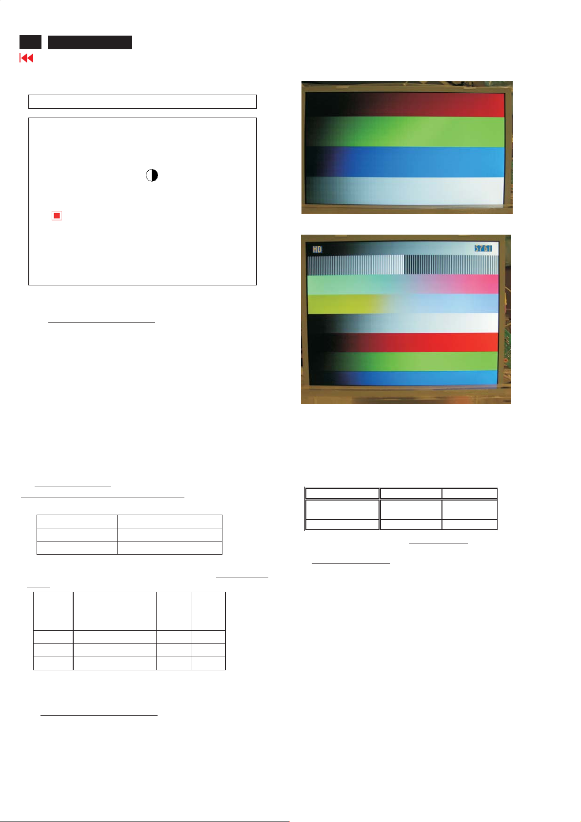
62
ME5P 15" & 20"
Go to cover page
Table 3.1: Readings withMinolta CA-110.
FACTORY ADJUST MENU
NORMAL
SCALER GAINRG B
AUTO-COLOR (OK)
ADC OFFSETRG B
ADC GAINRG B
PC OFFSETRG B
7119 SDTV ? SAT TINT
DVI SHIFT H V
TV SHIFT H V
HD SHIFT H V
RESERVE
HDTV ADC OFFSETRG B
HDTV ADC GAINRG B
VIDEOSCALER GAINRG B
SCALERHUE
EXITValue
Fig-1
4. PC mode display adjustment
Electrical Instructions
(Or FLUKE 54200, apply576i,DIGITAL SCAN/DIGI_ADC1 pattern.)
4.1 Displayquality adjustment
Use timing modeasdescribein2.2, and use the POPO (pixel on
pixel off) pattern to adjust theclock until no stripe and adjust the
phase until clear picture.(AUTO ADJUST hot key: press Volume –
andVolume +keys together for 1 second.)Check all preset 4
modes.
4.2 Wh ite-D adjustment (B )
4.2.1 At factor
pattern.Set main controls Brightness at 50% andContrast to 50%.
Select AUTO-COLOR function for ADC OFFSET andADCGAIN
setup.
4.2.2 Set smart picture as “N O R M A L ”
Set SCALER GAINRG B
VIDEOSCALER GAINRG B(alignment done).
The 1931 CIE chromaticity (X, Y) co-ordinates shall be
x(center) 0.292 ± 0.020
y(center) 0.293 ± 0.020
Readings withMinolta CA-110
4.2.3 Set Smart picture as “W A R M ”, and“COOL”The SCALER GAIN
R G B =
R gain R’ R’ R’-5
G gain G’ G’- 3 G’- 3
B gain B’ B’-7 B’
4.3 Chec k the analog interface cable
Check the color poor & noise condition of64gray pattern.
5. HDTV mode display adjustment
5.1 White balance adjustmen t (B)
General set-up:
Equipment :QuantumData Pattern Generator 801GD or 802G.
ymode apply 1024 X 768 /60Hz mode with64gray
=
Normal
Normal/ the R’\G’\B’
are gain after
alignment.
Apply 1080i,RGBW gray pattern.
WARM
COOL
Alignm ent met hod:
Initial Set-up:Set Smart picture as “P ersonal”,
Brightness=50,Color=50, Contrast=50)
Set AUTO-COLOR process.
Alignments :Check chromaticity(X,Y)co-
ordinatespecification:
Picture Mode xy
Personal
If out of specification,fine-tune HDTV ADC Gain
6. Preset DVI HDCP key
6.1 Dow nlo ad HDCP Key
The 284 bytes HDCP key shouldbe download to thesetvia I/F
cable using ATEat factoryAlignment tools
6.2 DVI Video HDCP KeyTes t
Use pattern generator
Equipment:Quantum 802R or 802BT or equivalent equipments.
Pattern :Standard HDCP Pattern (It’s color bar)
Timing : 720 X 480P 60Hz
Result :The PASS in
6.2.2 Use DVD Player:
Equipment:1.Pioneer (model: DV-S969AVi) or equivalent equipments.
2.DVD diskwith”Macro Vision “ protection.
Result :Thepictureshouldbeshown Normally.
0.292 ± 0.020 0.293 ±
0.020
in factorymode.
720 X 576P 50Hz
1280 X 720P 50Hz
1280 X 720P 60Hz
1920 X 1080i 50Hz
1920 X 1080i 60Hz
formation shouldbeshownonthe screen.
Page 63
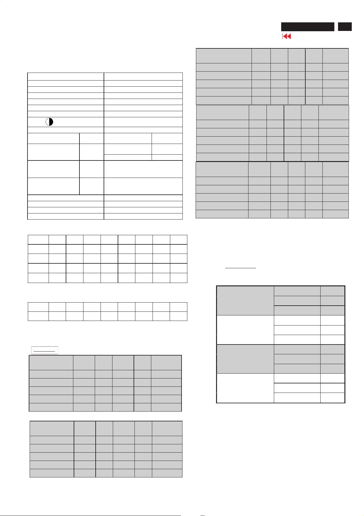
Electrical Instructions - For 15"
ME5P 15" & 20"
Go to cover page
63
.Preset EEPROM data
7.1EEPROM data has to bepresetdata according following table.
Funct ion
SCALER GAIN
ADC Offset R/G/B
ADC Gai n R/G/B
PC OFFset R/G/B
7119? brightness
7119Satu ratio n
7119 contrast
7119TINT
TV shift H
TV shift V
DVI SHIFTH
DVI SHIFTV
HD SHIFTH
HD SHIFTV
HD ADC OFFset R G B
HD ADC GAINRG B
Video Scaler Gain
Scaler Hue
Factorymode:
480i 480P 576i576P 720P/
HD shiftH153 152 166 165 65 66 38 35
HD shiftV39 40 50 52403959 59
DVIshiftH44 22 22 96 55 103 48
DVIshiftV40 43 5042415960
Factorymodepreset.
Preset val ue
127 127 127
127 127 127
127 127 127
127 127 127
127 (TV,AV,S-video,HD)
64 (TV,AV,S-video,HD)
70 (TV,AV,S-video,HD)
24 (TV,AV,S-video,HD)
Regular
NTSC PAL
150 165
9 16
See below.
See below.
127 127 127
127 127 127
127 127 127
50
720P/
60Hz
1080i/
50Hz
50Hz
1080i/
60Hz
PERS
S-Video
Brightness
Color
Contrast
Sharpness
Tint
ONAL RICH
50 50 45 47 50
50 60 56 56 65
50 54 55 54 58
50 83 83 83 83
50 50 50 50 50
PERS
HD (YPbPr)
Brightness
Color
Contrast
Sharpness
Tint
ONAL RICH
50 48 44 42 44
50 63 59 56 66
50 62 59 59 63
50 91 91 95 95
50 50 50 50 50
PERSO
DVI
Brightness
Color
Contrast
Sharpness
Tint
Smart Sound:THEATRER
Smart Sound
NAL RICH
50 48 44 42 44
50 63 60 56 66
50 57 54 54 57
50 91 91 95 95
50 50 50 50 50
Sound volume : 50
NAT
URE SOFT
NAT
URE SOFT
NAT
URE SOFT
MULTIM
EDIA
MULTIME
DIA
MULTIM
EDIA
In user “P icture alignment”
480i 480P 576i576P 720P/
HD shiftH62 62 59 5949492829
7.2 Smar t picture &Smart sound:
7.2.1FinalTV modeoutbox setting.
Smart Picture :Rich
Smart Picture
RF
Brightness
Color
Contrast
Sharpness
Tint
AV
Brightness
Color
Contrast
Sharpness
Tint
PERS
ONAL RICH
50 48 45 42 45
50 56 54 46 60
50 50 50 48 57
50 83 70 70 75
50 50 50 50 50
PERS
ONAL RICH
50 50 45 47 50
50 60 56 56 65
50 54 55 54 58
50 83 83 83 83
50 50 50 50 50
NATU
RE SOFT
NATU
RE SOFT
50Hz
720P/
60Hz
1080i
1080i
/50Hz
/60Hz
MULTIME
DIA
MULTIME
DIA
PERSONAL TREBLE 50
BASS 50
BALANCE 0
VOICE TREBLE 60
BASS 60
BALANCE 0
THEATER TREBLE 90
BASS 95
BALANCE 0
MUSICTREBLE 78
BASS 83
BALANCE 0
Incredible surround: OFF
AVL : OFF
Page 64
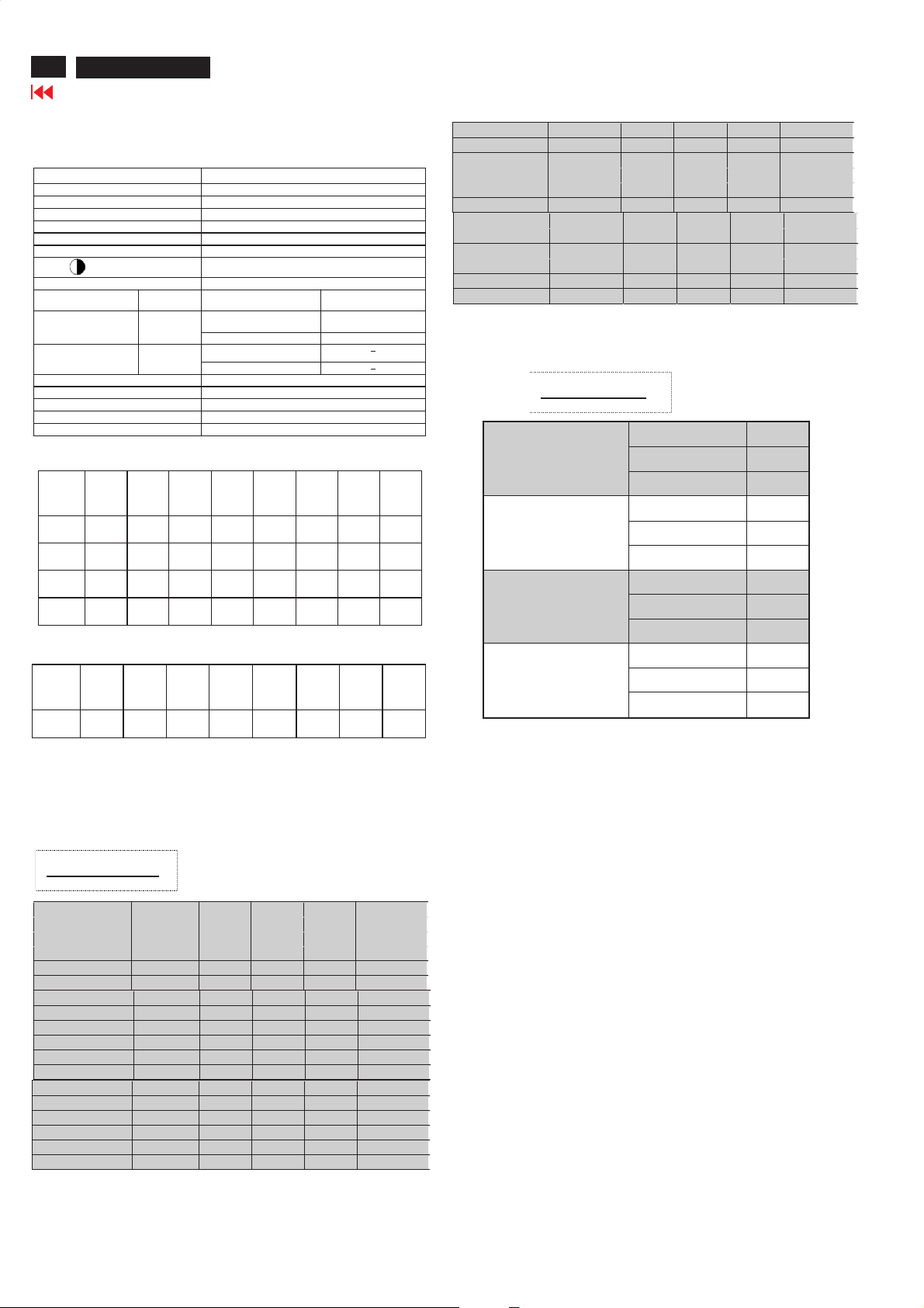
64
A
A
A
ME5P 15" & 20"
Go to cover page
Electrical Instructions- For 20"
7. Preset EEPROM data
7.1 EEPROM data has to bepresetdata according following table.
Factorymodepreset.
Function
SCALER GAIN
ADC Offset R/G/B
ADC Gain R/G/B
PC OFFset R/G/B
7119 ? brightness
7119 Saturat io n
7119 contrast
7119 TINT
TV shif t H
TV shif t V
HD SHIFTH
HD SHIFTV
HD ADC OFFset R G B
HD ADC GAINRG B
Video Scaler Gain
Scaler Hue
Regular
Preset value
127127127
127127127
127127127
127127127
127 (TV,AV,S-video,HD)
70 (TV,AV,S-video,HD)
75 (TV,AV,S-video,HD)
NTSC PAL
176 180
22 22
##
##
24(TV,AV,S-vi deo,HD)
127127127
127127127
127127127
50
Factorymode:
HD
shift H
HD
shift V
DVI
shift H
DVI
shift V
480i 480P576i 576P 720P
153 152 166 165 65 66 180 179
39 40 50 52 40 39 59 61
22 22 96 55 10348
43 50 41 40 59 59
/50H
z
720P
/60H
z
1080i
/50H
z
1080i
/60H
z
In user “P icture alignment”
HD
480i 480P576i 576P 720P
62 62 59 59 49 49 58 59
/50H
z
720P
/60H
z
1080i
/50H
z
1080i
/60H
z
shift H
HD (YPbPr) PERSONAL RICH NATURE SOFT MULTIMEDI
Brightness
Color
Contrast
Sharpness
Tint
DVI PERSONAL RICH NATURE SOFT MULTIMEDI
Brightness
Color
Contrast
Sharpness
Tint
50 35 37 30 46
50 72 70 65 80
50 78 71 71 82
50 87 87 87 87
50 50 50 50 50
50 35 37 30 46
50 72 70 65 80
50 78 71 71 82
50 87 87 87 87
50 50 50 50 50
Smart Sound:THEATRER
Sound volume :50
Smart Sound
PERSONAL TREBLE 50
BASS 50
BALANCE 0
VOICE TREBLE 60
BASS 60
BALANCE0
THEATRER TREBLE 90
BASS 95
BALANCE 0
MUSICTREBLE 78
BASS 83
BALANCE0
Incredible surround: OFF
AVL : OFF
7.2 Smart picture &Smart sound:
7.2.1 Final TV modeoutbox setting.
Smart picture :RICH
Smart Picture
RF PERSONAL RICH NATURE SOFT MULTIMEDI
Brightness
Color
Contrast
Sharpness
Tint
AV PERSONAL RICH NATURE SOFT MULTIMEDI
Brightness
Color
Contrast
Sharpness
Tint
S-Video PERSONAL RICH NATURE SOFT MULTIMEDI
Brightness
Color
Contrast
Sharpness
Tint
50 43 43 42 50
50 65 56 51 70
50 80 70 59 75
50 79 75 75 83
50 50 50 50 50
50 40 38 37 45
50 58 56 51 70
50 75 70 59 75
50 87 79 79 87
50 50 50 50 50
50 40 38 37 45
50 58 56 51 70
50 75 70 59 75
50 87 79 79 87
50 50 50 50 50
Page 65
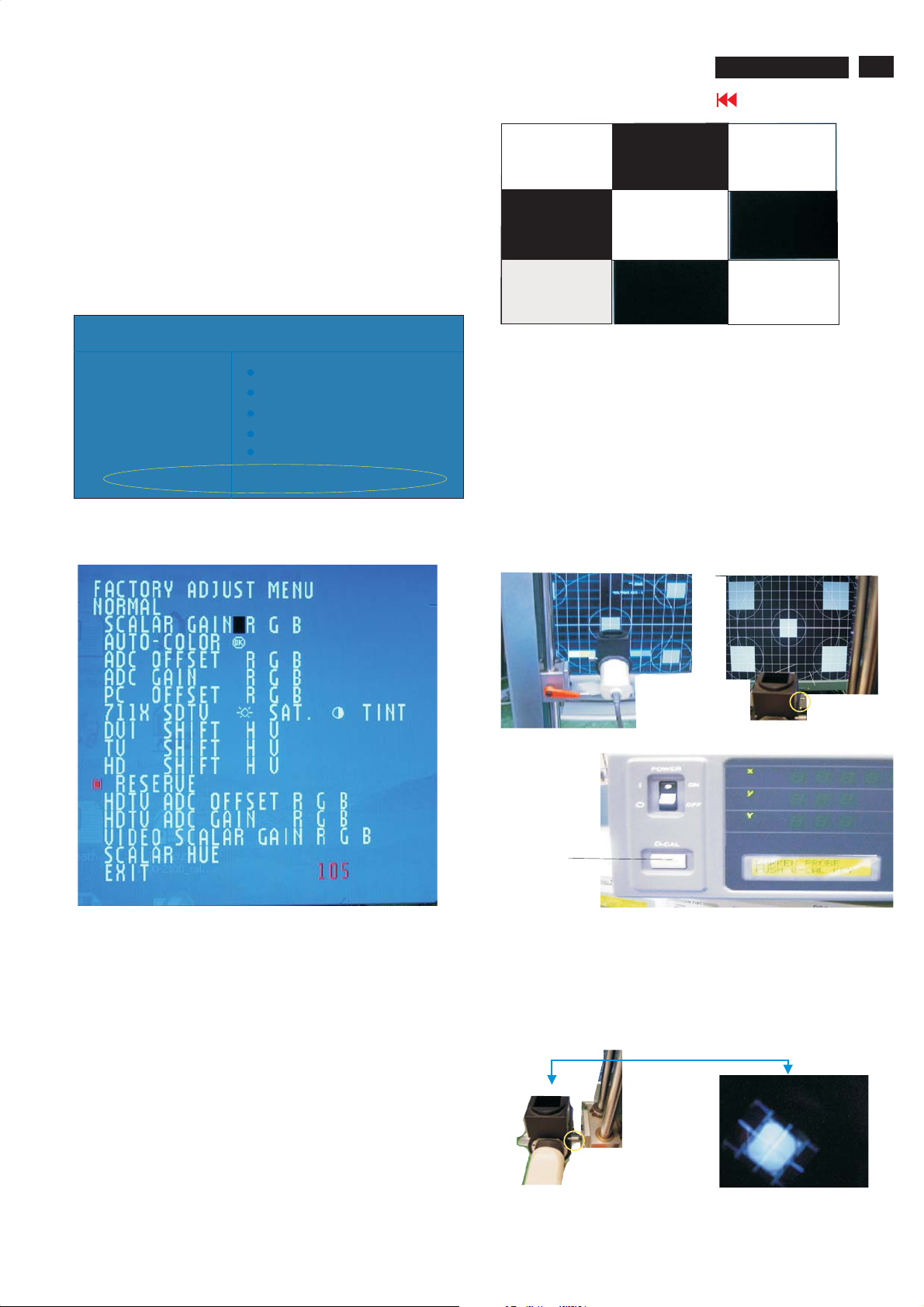
Display adjustment
Display adjustment
Access factory.Mode
how toget intofactorymode menu
Step 1:Selectthesource "PC" and then turn off LCD-TV.
Step 2:[Push"power"button and then push the "VOL- " and "VOL+"
buttons at the same time immediately and hold it] about fiveseconds
then release all buttons.
ME5P15" & 20"
Go to cover page
65
Fig.3
Press "menu"button and br
Fig.1
MAIN CONTROLS
PICTURE
ing up factorymode indicationasshownin
800X600@60HZ
SMARTPICTURE
AUDIO BR IGHTNESS
FEATURES CONTRAST
INSTALL AUTO ADJUST
MANUAL ADJUST
ME5P NAFTA20 V0.45.1 050527 AU20SVGA
Fig. 1
Use the CHNNEL- and CHNNEL+ to selectthe "F1/FL1 NAFTA V1.01.
05 041208 LG15XGA" and then press the "VOL +" button
2. Apply a 1024x768/60Hzsignal withwhite pattern.Set
brightness controlat50% and contrast controlat50%.Adjust the
R.G.B gain toreach special color temperature on centerof
screen.
2.1 Aim theprobe CA-A30 at the centerofscreen as Fig. 4
2.2 Removethe lens prote
2.3 Set Measuring/viewing selector toMeasuring position for reset
analyzer. (Zero calibration) as Fig. 5
2.4 Turn onthe colour analyzer (CA-110).
2.5 Press 0-CAL buttonto start reset analyzer. See Fig. 6
ctive coverofprobe CA-A30.
Cover (black)
Measurement viewing selector
Fig.4
Fig.5
Fig.2
PC mode WHITE-D adjustment (B)
1Apply 1024X768/60Hzmode with 5 block patternasFig 3.Set
main controls brightness controlat50% and contrast to 50% on
User mode.Set color setting at natural color on User mode.Move
cursor to "AUTO-color" item on fa
to activethis function, then scalerwill adjust RGB and Color
RGB automatically by it self.
ctorymode, press "menu" key
O-CAL
Fig.6
2.6 Switch lightprobetoViewing position.
2.7 Movethe Lens barrel forward or backwardtoget clear imageas
showninFig. 7
2.8 Switch lightprobetoMeasuring position. It should beable to
indicate colourvalue onthe CA-110.
Clear image
Measurement/viewing selector
Fig.7
Page 66
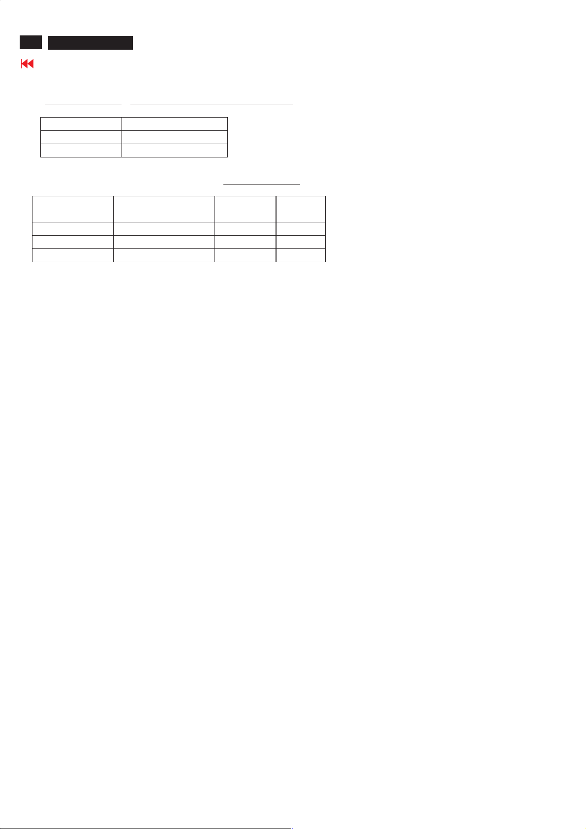
66
ME5P 15" & 20"
Go to cover page
Display Adjustment
2.9 Set smart picture as NORMAL
Set SCALER GAIN R G B
The 1931 CIE chromaticity (X, Y) co-ordinates shall be:
x (center) 0.292 ± 0.020
y (center) 0.293 ± 0.020
Readings with Minolta CA-110.
2.10 Set Smart picture as WARM , and COOL The SCALER GAIN R G B
.
Rgain R R R-5
G gain G G -3 G -3
Bgain B B-7 B
"
= VIDEO SCALER GAIN R G B(alignment done).
Nor mal/
"
Nor mal/ the R \G \B are
gain after alignment.
'
'
'
"
"
"
'
"
'
'
WARM COOL
'
'
'
=
'
'
'
Page 67
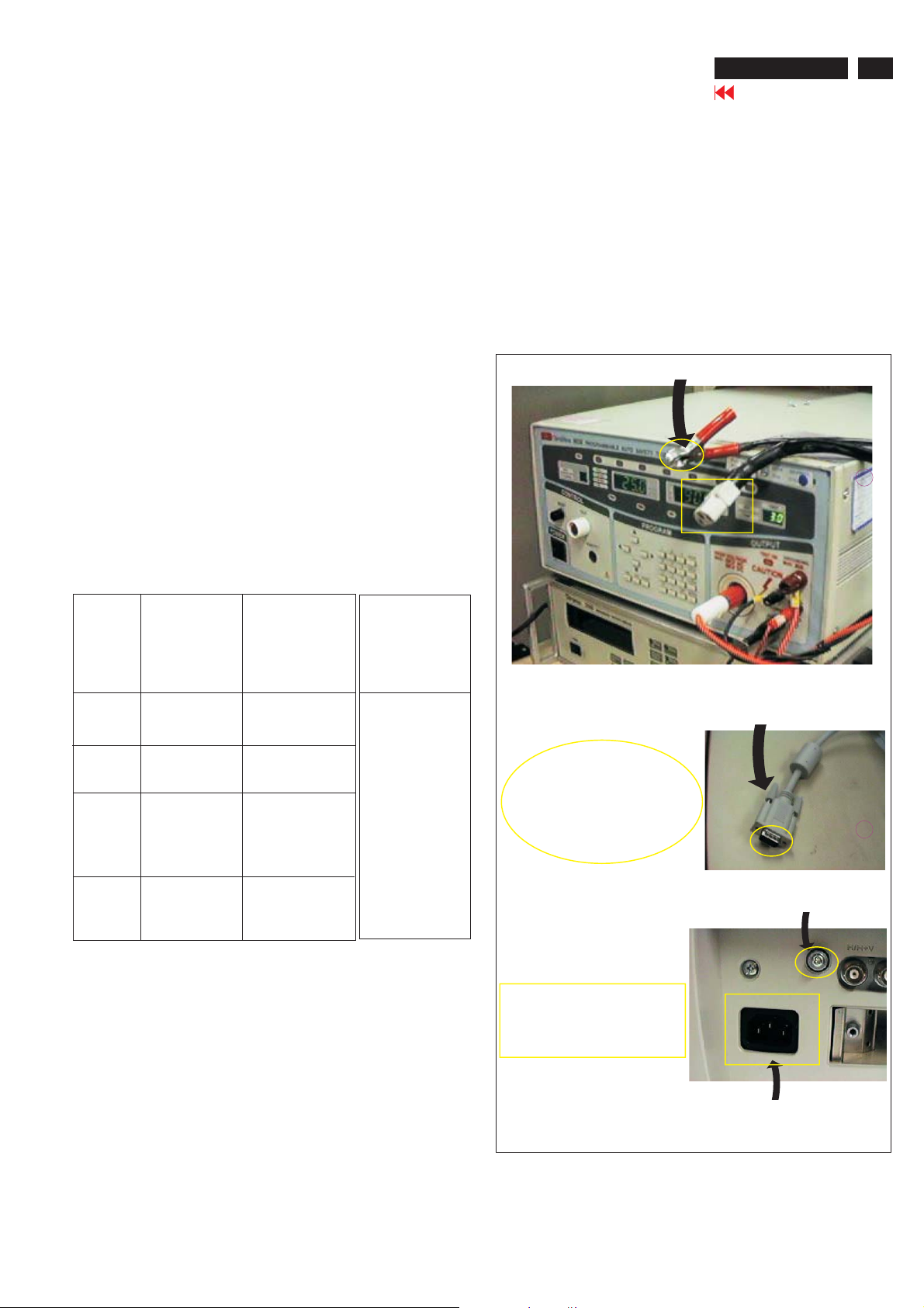
Safety Test Requirements
ME5P 15" & 20"
Go to cover page
67
All units that are returned for service or repair must pass the
original manufactures safety tests. Safety testing requires both
and testing.Hipot Ground Continuity
HI-POT TEST INSTRUCTION
1.Application requirements
1.1 All mains operated products must pass the Hi-Pot test as
described in this instruction.
1.2 This test must be performed again after the covers have
been refitted following the repair, inspection or modification
of the product.
2.
Test method
2.1 Connecting conditions
2.1.1 The test specified must be applied between the parallel-
blade plug of the mainscord and all accessible metal
parts of the product.
2.1.2 Before carrying out the test, reliable conductive
connections must be ensured and thereafter be
maintained throughout the test period.
2.1.3 The mains switch(es) must be in the "ON" position.
2.2 Test Requirements
All products should be HiPot and Ground Continuity tested as
follows:
3. Equipments and Connection
3.1. Equipments
For example :
- ChenHwa 9032 PROGRAMMABLE AUTO SAFETY
TESTER
- ChenHwa 510B Digital Grounding Continuity Tester
- ChenHwa 901 (AC Hi-pot test), 902 (AC, DC Hi-pot test)
Withstanding Tester
3.2. Connection
* Turn on the power switch of monitor before Hipot and
Ground Continuity testing.
Clip
Clip
Condition HiPot Test for HiPot Test for Ground Continuity
products where products where Test requirement
the mains input the mains input is
range is Full 110V AC(USA
range(or 220V type)
AC)
Test 2820VDC 1700VDC Test current:
voltage (2000VAC) (1200VAC) 25A,AC
Test time:
Test time 3 seconds 1 second 3 seconds(min.)
(min.) Resistance
required:
Trip set at 100 uA 5 mA <=0.09+Rohm,
current for Max. R is the
(Tester) limitation; set resistance of
at 0.1 uA for the mains cord.
Min. Limitation
Ramp set at 2
time seconds
(Tester)
2.2.1 The minimum test duration for Quality Control Inspector
must be 1 minute.
2.2.2 The test voltage must be maintained within the specified
voltage + 5%.
(ChenHwa 9032 tester)
Video cable
Connect the "video cable"
or "grounding screw"
to the CLIP on your tester.
Grounding screw
Connect the power cord
to the monitor.
2.2.3 There must be no breakdown during the test.
2.2.4 The grounding blade or pin of mains plug must be
conducted with accessible metal parts.
Power outlet
(Rear view of monitor)
Hipot and Ground Continuity testing records have to be kept
for a period of 10 years.
Page 68
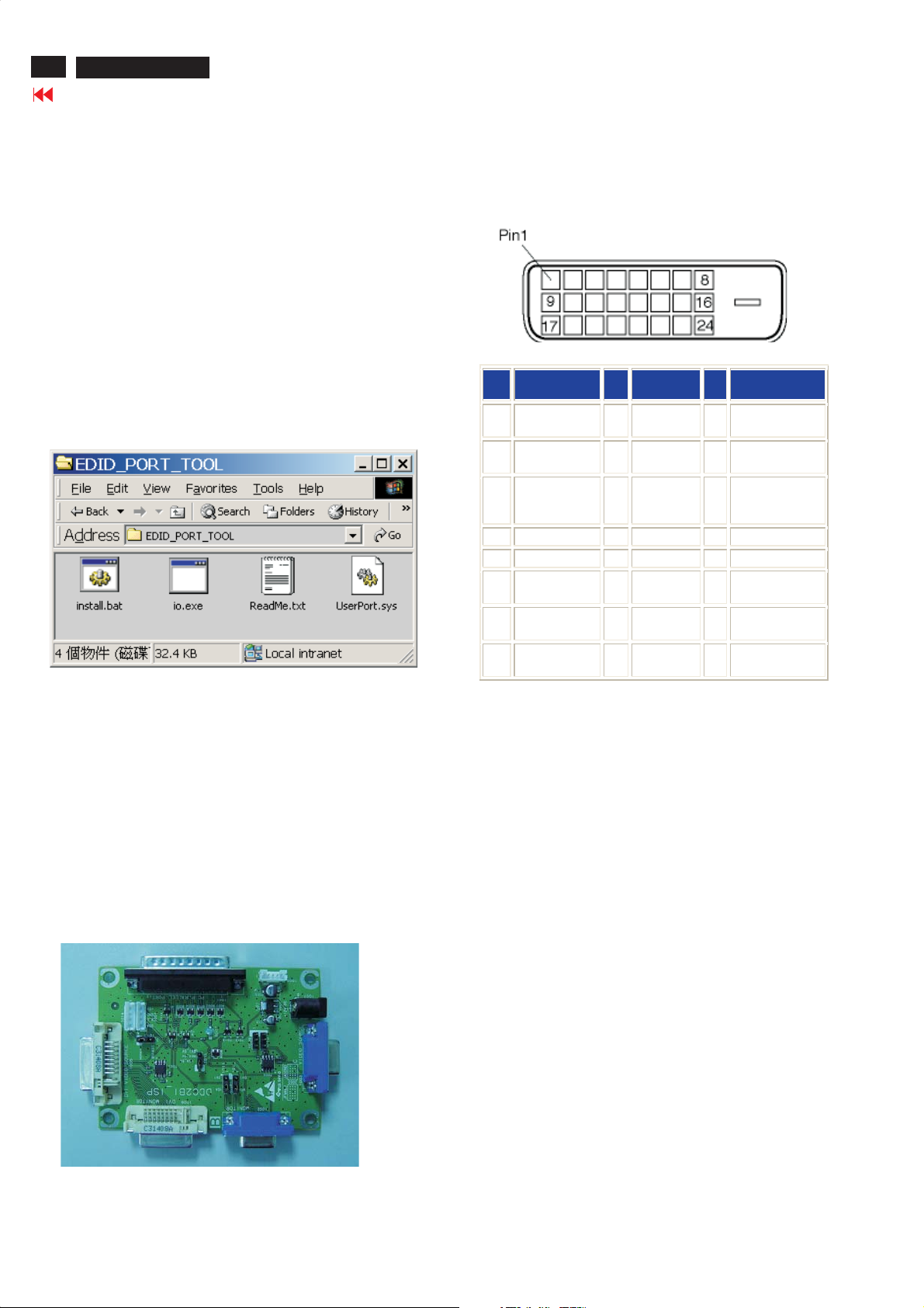
68
ME5P 15" & 20"
Go to cover page
DDC Instructions
General
DDC Data Re-programming
In case the DDC data memory IC or main EEPROM which storage all
factory settings were replaced due to a defect, the serial numbers have
to be re-programmed" ".
It is advised to re-soldered DDC IC and main EEPROM from the old
board onto the new board if circuit board have been replaced, in this
case the DDC data does not need to be re-programmed.
Additional information
Additional information about DDC (Display Data Channel) may be
obtained from Video Electronics Standards Association (VESA). Extended
Display Identification Data(EDID) information may be also obtained from
VESA.
Analog DDC IC, & EEPROM
System and equipment requirements
1. An i486 (or above) personal computer or compatible.
2. Microsoft operation system Windows 95/98 .
Y o Install the EDID_PORT_Tool under Win2000/XP . As
ou have t
Fig. 1 .
Fig. 1Fig. 1
Pin Assignmen t
The digital only connector contains 24 signal contacts organized in
three rows of eight contacts. Signal pin assignments are listed in the
following table:
To Printer port
DC 8~12V
DC 8~12V
Power
indicator
1.
Power
indicator
Pin
Signal
No.
Assignment
T.M.D.S.
1
Data2-
T.M.D.S.
2
Data2+
T.M.D.S.
3
Data2/4 Shield
4 No connect 12 No connect 20 No connect
5 No connect 13 No connect 21 No connect
6 DDC Clock 14 +5V Power 22
7 DDC Data 15
8 No connect 16
To Monitor
D-sub/DVI cable
To Monitor
D-sub cable
Pin
No.
9
10
11
Signal
Assignment
T.M.D.S.
Data1-
T.M.D.S.
Data1+
T.M.D.S.
Data1/3
Shield
Ground (for
+5V)
Hot Plug
Detect
Fig. 3Fig. 3
Pin
Signal
No.
Assignment
17 T.M.D.S. Data0-
T.M.D.S.
18
Data0+
T.M.D.S.
19
Data0/5 Shield
T.M.D.S. Clock
Shield
23 T.M.D.S. Clock+
24 T.M.D.S. Clock-
A. Cody the "UserPort.sys" to C:\WINNT\system32\drivers(win2000)
C:\WINDOWS\system32\drivers(winXP)
B. Running " io.exe" everytime, Before you start to programming
edid data .
3. EDID46 Release For writing block4.EXE program .
4. DDC 2BI-ISP TOOL:
Inclusion :
A. DDC2BI-ISP TOOL(3138 106 10396) x1 (as Fig. 2)
B. Printer cable x1
c. (D-Sub) to (D-Sub) cable x2
D. D-SUB to DVI cable X1
Note: The EDID46.EXE is a windows-based program, which cannot
be run in MS-DOS.
To Printer port
Fig. 2Fig. 2
Page 69
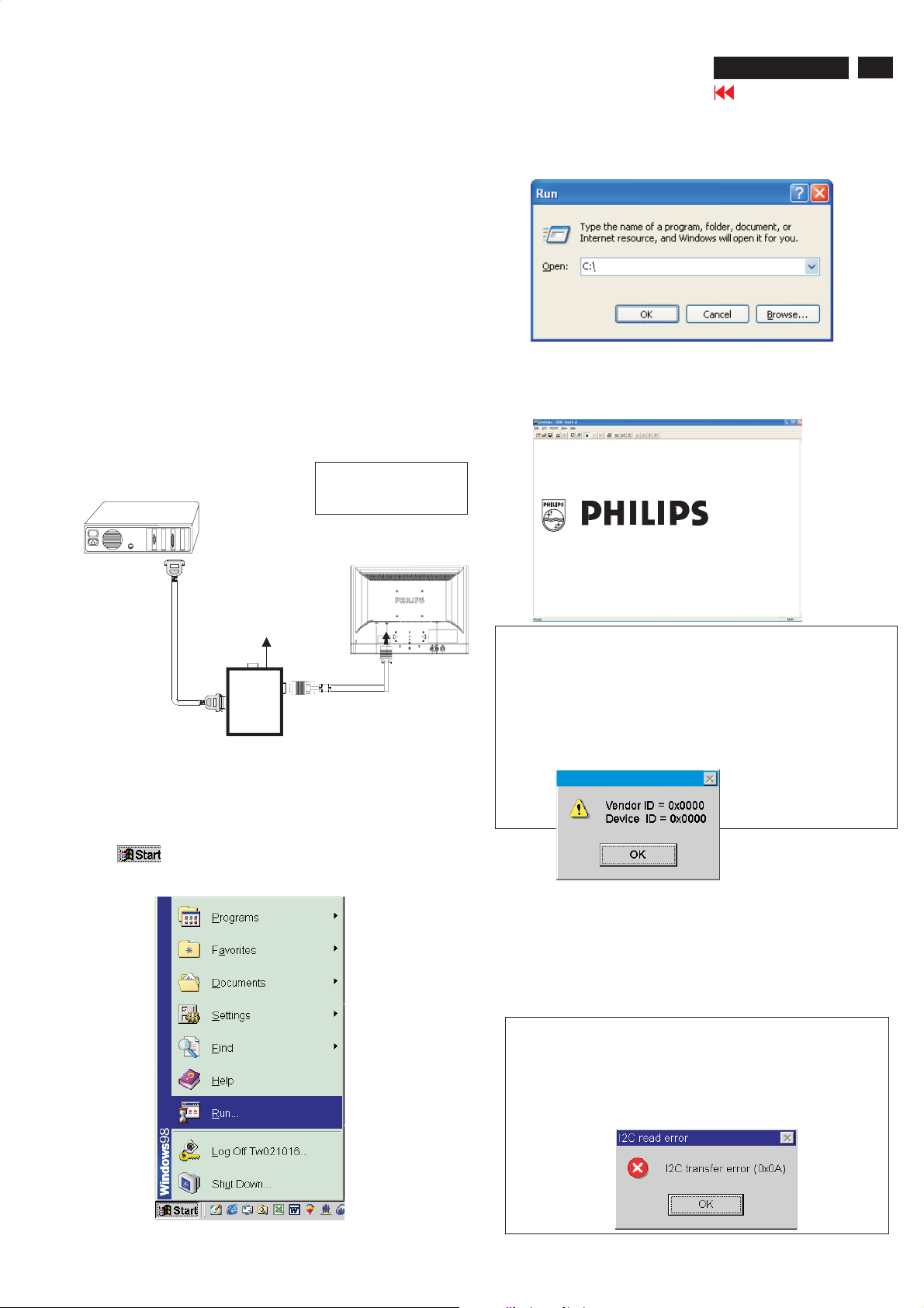
DDC Instructions
ME5P 15" & 20"
Go to cover page
69
Configuration and procedure
There are 3 chips contained OSD string, serial number..etc
on the circuit board, main EEPROM which storage all factory settings,OSD
string. DDC IC which storage 128byte EDID data(serial number ..etc.).
Following descirptions are the connection and procedure for Analog
/Digital and main EEPROM can be re-programmed along with
Analog/Digital IC by enable factory memory data write function on the
DDC program (EDID45.EXE).
Initialize alignment box
In order to avoid that monitor entering power saving mode due
to sync will cut off by alignment box, it is necessary to initialize
alignment box before running programming software
(EDID45.EXE). Following steps show you the procedures and
connection.
Step 1: Supply 8-12V DC power source to the Alignment box by
plugging a DC power cord or using batteries.
Step 2: Connecting printer cable and D-Sub cable of monitor as Fig. 4
PC
1=Power connector
2=D-SUB/DVI connector
3. At the submenu, type the letter of your computer's hard disk drive
followed by :EDID45 (for example, C:\EDID45, as shown in Fig. 6).
Edid45.exe
Fig. 6
4. Click button. The main menu appears (as shown in Fig. 7).OK
This is for initialize alignment box.
DC Power
8-12 V
----->
2
Printer
Port
To P C
To Monitor
Fig. 4
To printer port (LTP1)
Step 3: Installation of EDID45.EXE
Method 1: Start on DDC program
Start Microsoft Windows.
1. The Program"EDID45.EXE" in service manual cd-rom be copyed to C:\ .
2. Click , choose Run at start menu of Windows as shown
In Fig. 5.
----->
1
Fig. 7
Note 1: If the connection is improper, you will see the following error
message (as shown in Fig. 8) before entering the main menu.
Meanwhile, the (read EDID) function will be disable. At this
time,
please make sure all cables are connected correctly and
Edid45.1
Fig. 8
1
Note 2: During the loading, EDID45 will verify the EDID data which just
loaded from monitor before proceed any further function, once
the data structure of EDID can not be recognized, the following
error message will appear on the screen as below. Please
confirm following steps to avoid this message.
1. The data structure of EDID was incorrect.
2. DDC IC that you are trying to load data is empty.
3. Wrong communication channel has set at configuration setup
Fig. 5
Fig. 9
Page 70
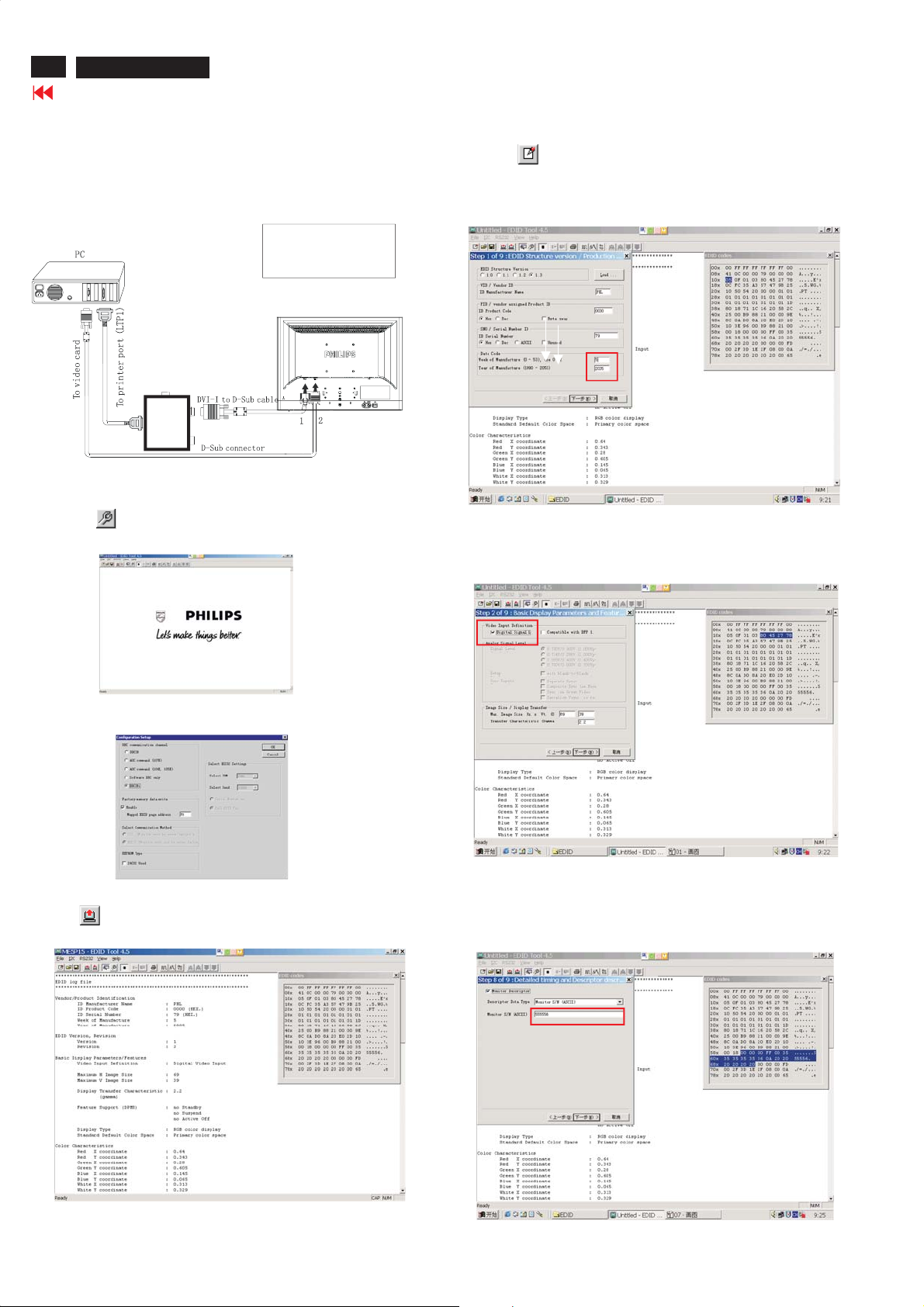
70
ME5P 15" & 20"
Go to cover page
DDC Instructions
Re-programming Digital DDC IC
Step 1: After initialize alignment box, connecting all cables and
box as shown in Fig. 10
1=DVI connector
2=D-SUB connector
3=Power Plug
3
To PC
To Monitor
Printer
Port
Fig.10
Step 2: Read DDC data from monitor
1. Click icon as shown in Fig. 11 from the tool bar to bring up
the Channels "Configuration Setup" windows as shown in Fig. 12.
Step 3: Modify DDC data (verify EDID version, week, year)
1. Click (new function) icon from the tool bar, bring up
Step 1 of 9 as shown in Fig. 14 .
EDID45 DDC application provides the function selection and
text change (select & fill out) from Step 1 to Step 9.
To Printer port
DC 8~12V
DC 8~12V
To Monitor
To Monitor
D-sub/DVI cable
D-sub/DVI cable
Select and fill out,
If necessary.
Fig. 14
Step 4: Modify DDC data (Monitor Serial No.)
Next1. Click , bring up Fig. 15. Then select Digital Signal as below
Fig. 11
2. Select the DDC2Bi as the communication channel.
As shown in Fig. 12.
Fig. 12
3. Click OK button to confirm your selection.
4. Click icon (Read EDID function) to read DDC EDID data from
monitor. The EDID codes will display on screen as shown in Fig. 13.
Fig. 15
2. Click to step7, bring up Fig. 16.Next
- Serial number can be filled up or be changed at this moment.
- Click Next, Finish to exit the Step window.
Fig. 13
Don't close this screen. --->
Fig. 16
Page 71
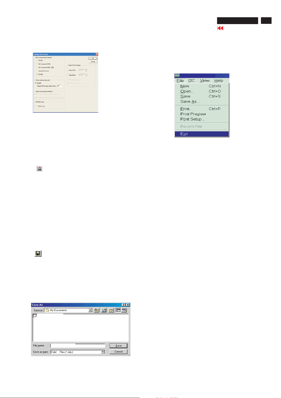
DDC Instructions
ME5P 15" & 20"
Go to cover page
71
Step 5: Write DDC data
1. Configuration should be as Fig. 17. And press OK.
Fig. 17
Access factory. Mode
Step1:Select the source "PC" and then turn off LCD-TV.
Step 2 : [Push "power " button and then push the "VOL- " and "VOL+"
buttons at the same time immediately and hold it] about five seconds
then release all buttons.
Press "menu"button and bring up factory mode indication
3. Click (Write EDID) icon from the tool bar to write DDC data.
Bring up "Writing 0%~100%, ready" a progressing bar on the left
down corner.
4. Turn off/on monitor
Step 7: Exit DDC program
Pull down the File menu and select Exit as shown in Fig. 19.
Fig. 19
Step 6: Save DDC data
Sometimes, you may need to save DDC data as a text file for using
in other IC chip. To save DDC data, follow the steps below:
1. Click (Save) icon (or click "file"-> "save as") from the tool bar
And give a file name as shown in Fig. 18.
The file type is EDID45 file (*.ddc) which can be open in WordPad.
By using WordPad, the texts of DDC data & table (128 bytes, hex
code) can be modified. If DDC TEXTS & HEX Table are completely
correct, it can be saved as .ddc flie to re-load it into DDC IC for DDC
Data application.
150S5-DDC
ME5P15-DDC
C:\My documents\ME5P15-DDC
45
Fig. 18
2. Click .Save
Page 72

72
ME5P 15" & 20"
Go to cover page
DDC Data - For 15"
**********************************************************************
EDID log file
**********************************************************************
Vendor/Product Identification
ID Manufacturer Name : PHL
ID ProductCode : 4650 (HEX.)
ID Serial Number : 1010101 (HEX.)
Week ofManufacture:0
Year ofManufacture:2005
EDID Version, Revision
Versio
n:1
Revision:3
Basic DisplayParameters/Features
Video InputDefinition:DigitalVideo Input
Compatible withVESADFP 1.x
Maximum H Image Size : 30
Maximum V Image Size : 23
DisplayTransferCharacteristic : 2.4
(gamma)
Feature Support (DPMS) : Standby
Suspend
Active Off
DisplayType : RGBc
olor display
Standard DefaultColor Space : Primarycolor space
Preferred Timing Mode : Detailed timing block 1
Color Characteristics
Red X coordinate:0.635
Red Y coordinate : 0.334
Green X coordinate : 0.295
Green Y coordinate:0.587
Blue X coordinate:0.147
Blue Y coordinate:0.096
Whit
eXcoordinate : 0.296
WhiteYcoordinate : 0.308
Established Timings
Established Timings I : 640 x 480 @60Hz (IBM,VGA)
800 x 600 @56Hz (VESA)
800 x 600 @60Hz (VESA)
Manufacturer's timings :
Standard Timing Identification : Unused
Monitor Descriptor #1
Serial Number :
Monitor Descriptor #2
Serial Number :
Monitor Descriptor #3
Monitor Name : PHILIPS ME5P
Monitor Descriptor #4
Monitor Range Limits
Min. VtrateHz : 58
Max. V
trateHz : 62
Min. Horiz. ratekHz : 30
Max. Horiz. ratekHz : 49
Max. Supported Pixel : 70
No secondaryGTFtiming formula supported.
Extension Flag:0
Check sum : 5E(HEX.)
**********************************************************************
EDID data (128 bytes)
**********************************************************************
0: 00 1:ff 2:ff 3:ff 4:ff 5:ff 6:ff 7:00
8: 41 9: 0c 10: 50 11:46 12: 0113: 0114: 0115:01
16: 00 17: 0f 1 8: 0119: 03 20: 81 21: 1e 22: 17 23: 8c
24: ee 25: a9 26: ef 27: a2 28: 55 29: 4b 30: 96 31:25
32: 18 33: 4b 34: 4e 35: 23 36: 08 37: 00 38: 01 39: 01
40: 01 41:01 42: 01 43: 01 44: 01 45:01 46: 01 47: 01
48: 01 49: 0150: 0151:0152: 0153: 0154: 00 55:00
56: 00 57: ff 58: 00 5
64: 20 65: 20 66: 20 67: 20 68: 20 69: 20 70: 20 71:20
72: 00 73: 00 74: 00 75: ff 76: 00 77: 0a 78: 20 79: 20
80: 20 81: 20 82: 20 83: 20 84: 20 85: 20 86: 20 87: 20
88: 20 89: 20 90: 00 91: 00 92: 00 93: fc 94: 00 95: 50
96: 48 97: 49 98: 4c 99: 49 100: 50 101: 53 102: 20 103: 4d
104: 45105:35106: 50 107: 0a108: 00 109: 00 11 0: 00 111:fd
112: 00 113: 3a114: 3e 115: 1e 116: 31117: 07 118: 00 119: 0a
120: 20 121:20 122: 20 123: 20 124: 20 125:20 126: 00 127:
9: 0a 60: 20 61: 20 62: 20 63: 20
5e
Established Timings II : 1024 x 768 @60Hz (VESA)
Page 73

DDC Data - For 20"
ME5P 15" & 20"
Go to cover page
73
***************************************************
EDID log file
***************************************************
Vendor/Product Identification
EDID Version, Revision
B
asic DisplayParameters/Features
Color Characteristics
Established Timings
ID Manufacturer Name : PHL
ID ProductCode : C008 (HEX.)
ID Serial Number : 499602D2 (HEX.)
Week ofManufacture:41
Year ofManufacture:2005
Version:1
Revision:3
Video InputDefinition:DigitalVideo Input
Maximum H Image Size : 41
Maximum V Image Size : 31
DisplayTransferCharacteristic : 2.4
(gamma)
Feature Support (DPMS) : Standby
DisplayType : RGBcolor display
Standard DefaultColor Space : Primarycolor space
Preferred Timing Mode : Detailed timing block 1
Red X coordinate:0.642
Red Y coordinate:0.337
Green X coordinate:0.284
Green Y coordinate:0.615
Blue X coordinate:0.141
Blue Y coordinate:0.
WhiteXcoordinate:0.273
WhiteYcoordinate:0.292
Established Timings I : 640 x480 @60Hz (IBM,VGA)
Established Timings II :
Compatible withVESADFP1.x
068
800 x600 @56Hz (VESA)
800 x600 @60Hz (VESA)
Suspend
Active Off
Standard Timing Identification:Unused
Monitor Descriptor #1
Monitor Descriptor #2
Monitor Descriptor #3
Monitor Descriptor #4
Extension Flag:0
Check sum : ED (HEX.)
**********************************************************************
EDID data (128bytes)
**********************************************************************
0: 00 1: ff 2:ff 3:ff 4:ff 5:ff 6:ff 7:00
8: 41 9: 0c10: 08 11: c0 12:d2 13: 02 14: 96 15: 49
16: 29 17: 0f 18: 01 19: 03 20:81 21: 29 22:1f 23: 8c
24: ee 25: 5e 26: 23
32: 11 33: 46 34: 4a 35: 23 36: 00 37: 00 38: 0139:01
40: 01 41: 0142: 0143:01 44: 01 45: 01 46: 0147:01
48: 0149:0150: 01 51: 0152: 01 53: 01 54: 00 55: 00
56: 00 57: fa 58: 00 59: 0160: 01 61: 0162: 0163:01
64: 01 65: 01 66: 0167:01 68: 01 69: 0
72: 00 73: 00 74: 00 75: ff 76: 00 77: 0a 78: 20 79: 20
80: 20 81: 20 82: 20 83: 20 84: 20 85: 20 86: 20 87: 20
88: 20 89: 20 90: 00 91: 00 92: 00 93: fc 94: 00 95: 50
96: 48 97: 49 98: 50 99: 49 100:50 101: 53 102: 20 103: 4d
104: 45 105: 35 106: 50 107: 0a 108: 00 109: 00 110: 00 111: fd
11
120: 20 121: 20 122: 20 123: 20 124: 20 125: 20 126: 00 127: ed
Standard Timing Identification : Unused
Serial Number :
Monitor Name : PHILIPS ME5P
Monitor Range Limits
Min. VtrateHz : 56
Max. VtrateHz : 62
Min. Horiz. ratekHz : 30
Max. Hor
Max. Supported Pixel : 40
No secondaryGTFtiming formula supported.
2: 00 113: 38 114: 3e 115: 1e 116: 28 117: 04 118: 00 119: 0a
iz. ratekHz : 40
27: a4 28: 56 29: 48 30:9d 31:24
170: 0171:0a
Manufacturer's timings :
Page 74
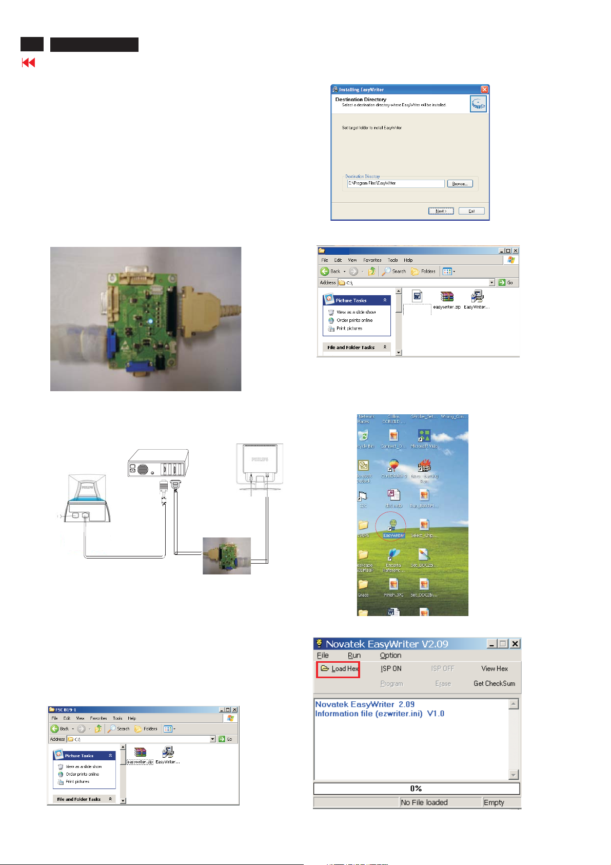
74
ME5P 15" & 20"
Go to cover page
Configuration and procedure
Firmware Upgrade for CPU
"Easywriter " The software
is provided by Novatek to upgrade the
firmware of CPU.
It is a windows-based program, which cannot be run in MS-DOS.
DDC2BI_ISP TOOL (3138 106 10396)
is for the interface between
"Parallel Port of PC" and "15 pin-D-SUB connector of Monitor".
System and equipment requirements
1. An i486 (or above) personal computer or compatible.
2. Microsoft operation system Windows 95/98/2000/XP.
3. ISP Software " Easywrite "
4. as shown in Fig. 1
DDC2BI_ISP TOOL (3138 106 10396)
ParallelPorttoPrintPortinPC
D-SUB to monitor
Fig. 1
5 Connect and Mains cord to Monitor as shown
. DDC2BI_ISP TOOL
in Fig. 2.
PC
170C6(B)
Fig. 4
Step 5 :Copy the hex file to C:\ME5P 15&20 as shown in Fig. 5 .
ME5P
ME5P 15&20
MF5_NAFTA_15
_ALL.hex
Fig. 5
Update the firmware
1. DoubleclicktheEasywriter.exeiconindesktopthenappears
window as shown in Fig.7 .
Monitor (A)
------------------------------->
Connect to
Mains cord
Connect to Mains
cord at this moment.
To video card
ISP box
Video cable
To printer port (LTP1)
Fig.2
6. Install and setup the Easywriter program
Step 1 : Make a folder in your PC as shown in Fig. 3.
For example : C:\ME5P 15&20
Step 2 : Copy the Software Easywriter into your folder
.zip
as shown in Fig.3.
Step 3 : Unzip Easywriter.zip into your folder as shown in Fig. 3.
Step 4 : Double click the EasywriterV2.09a_user.exe icon to install the
Application as Fig. 4.
ME5P 15&20
Fig. 6
Fig. 3
Fig. 7
Page 75
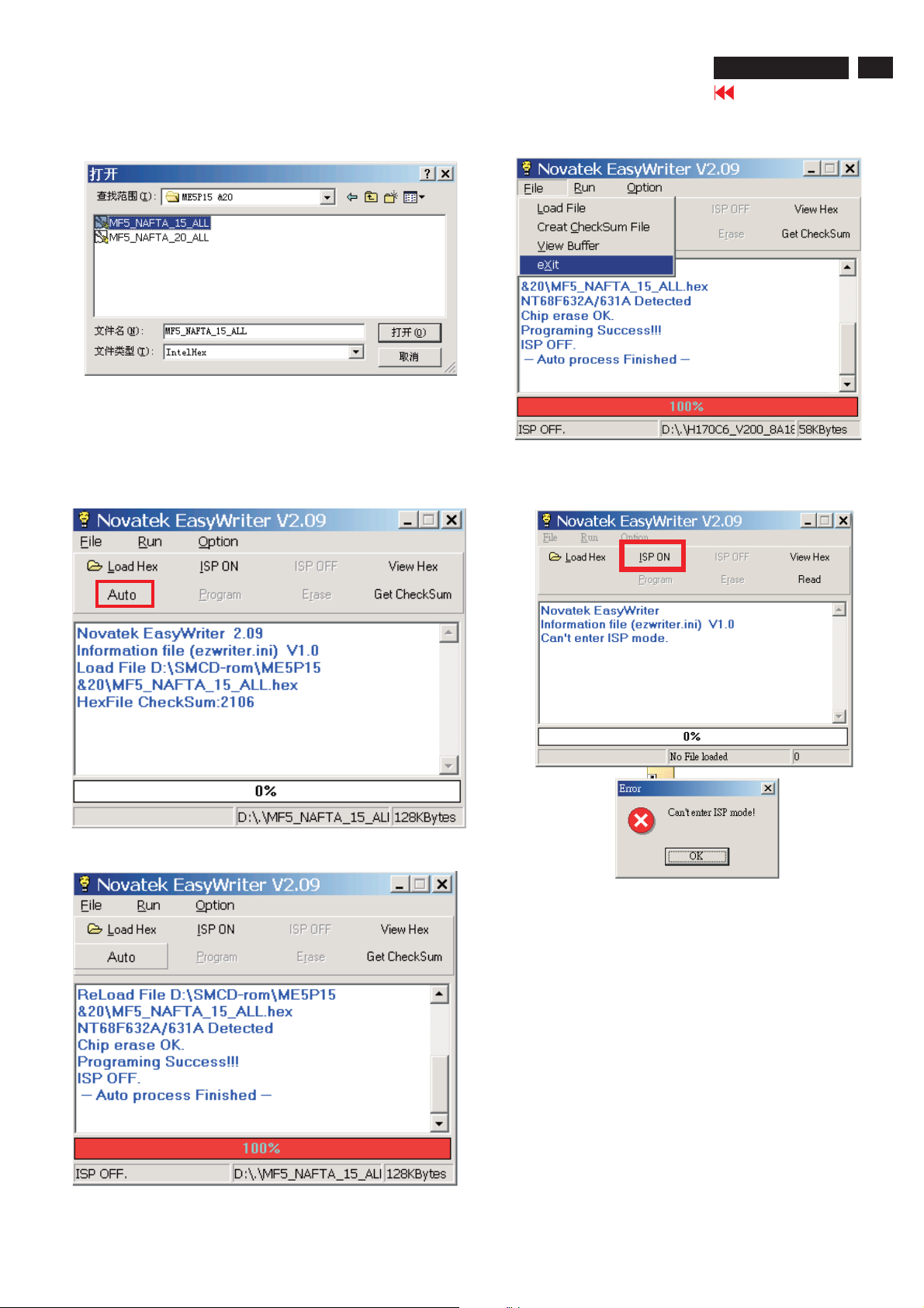
Firmware Upgrade for CPU
ME5P 15" & 20"
Go to cover page
75
2. Press the Load hex then select the hex file as shown
in Fig. 8.
4 Press the AUTO to running program ,
the firmware be updated as shown in Fig. 9-10
4 Pressthe file-->exit toend program ,asshown inFig.11.
Fig. 8
Fig. 11
If there is a warring message coming as shown in Fig 12. , you
havetochecktheACpower,Videocable,orNovatekMCU.
Fig. 9
2.09
Fig. 12
Fig. 10
Page 76
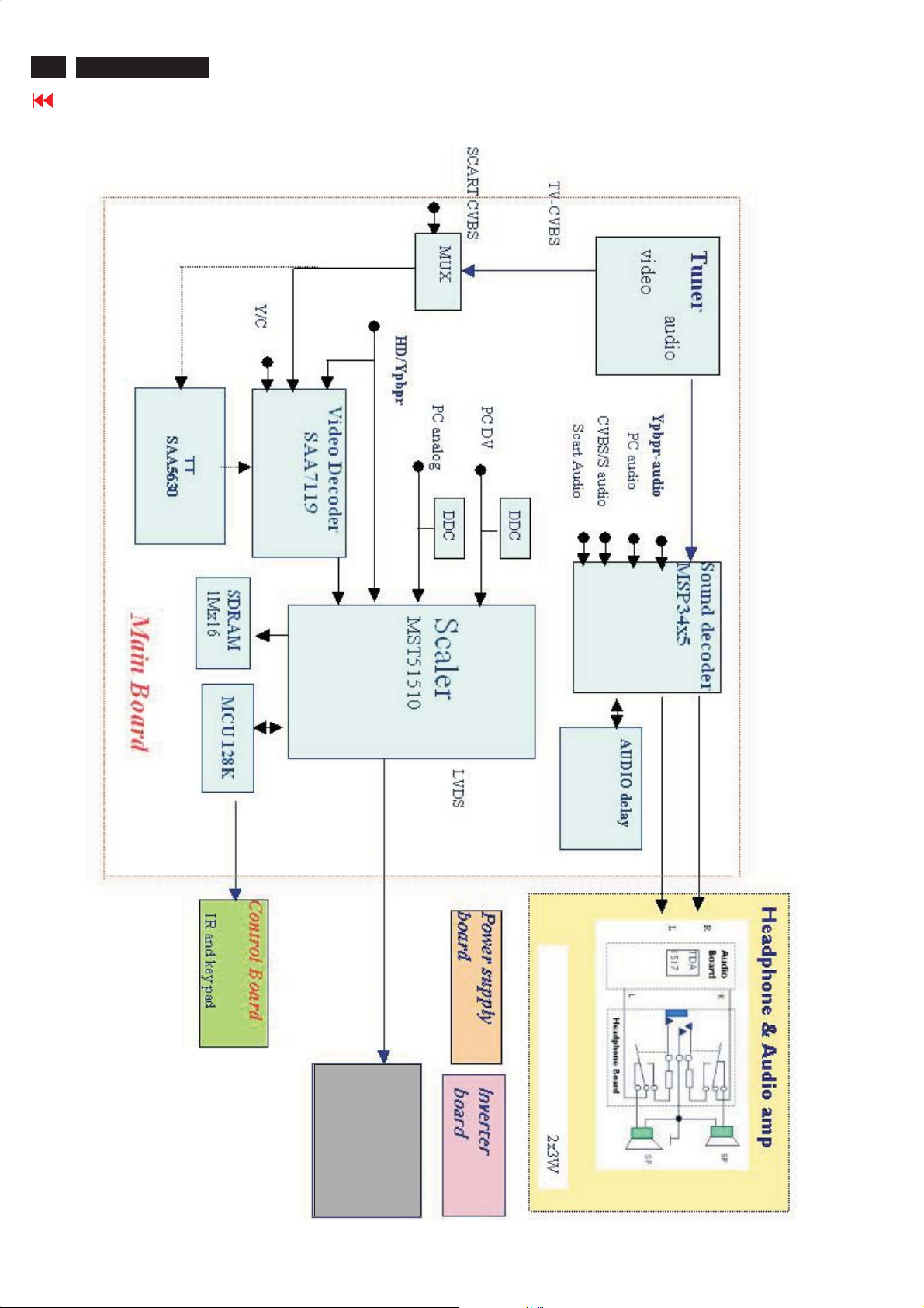
76
ME5P 15" & 20"
Go to cover page
Function Block Diagram
PANEL
Page 77
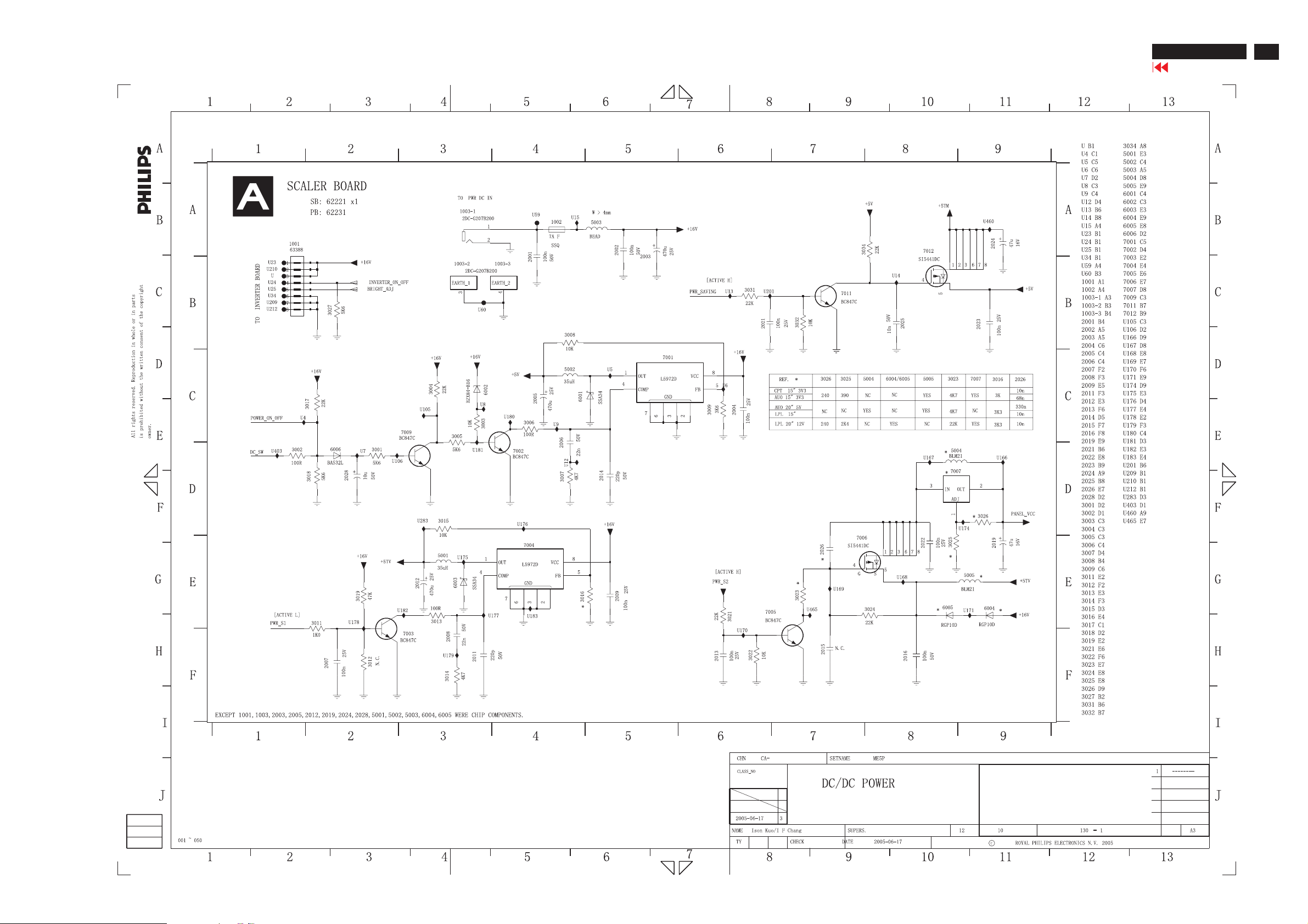
Schematic Diagram of scaler1-for15"&20"
ME5P 15" & 20"
Go to cover page
77
Page 78
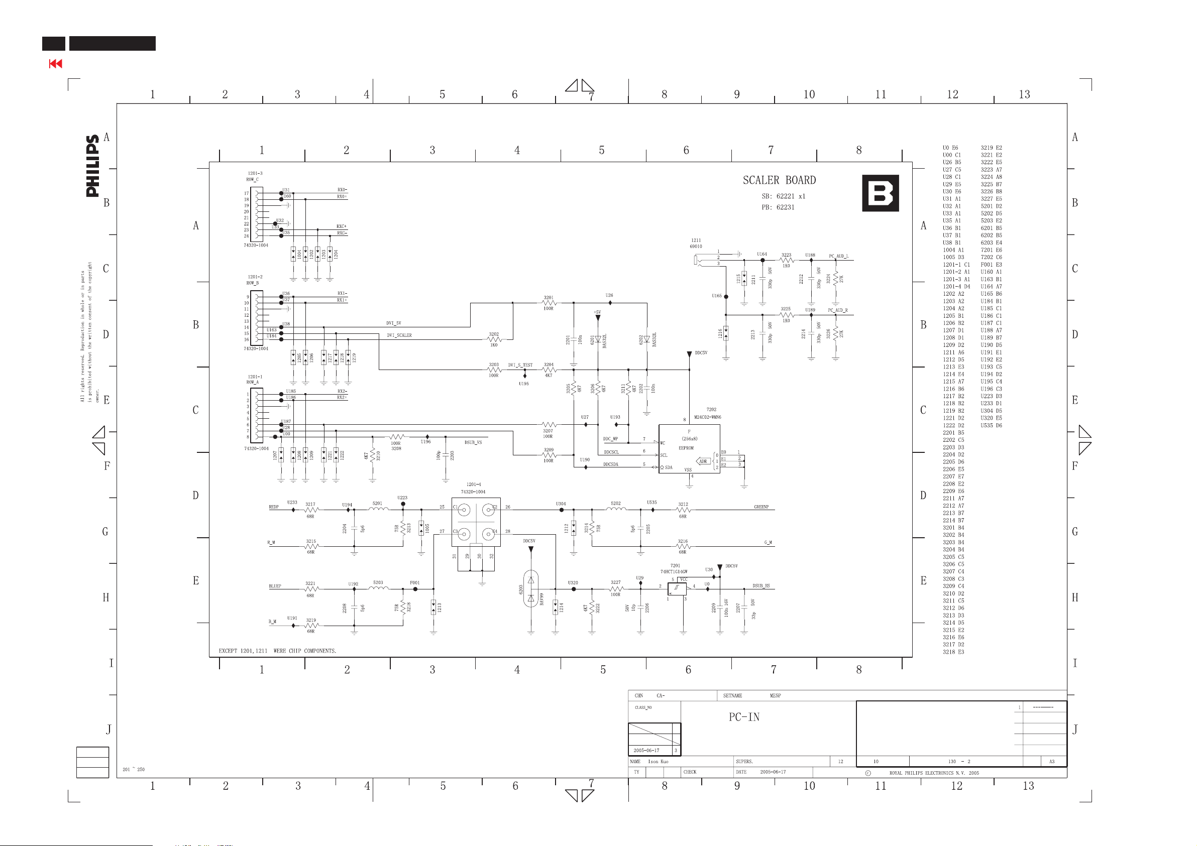
78
ME5P 15" & 20"
Go to cover page
Schematic Diagram of scaler2-for15"&20"
Page 79
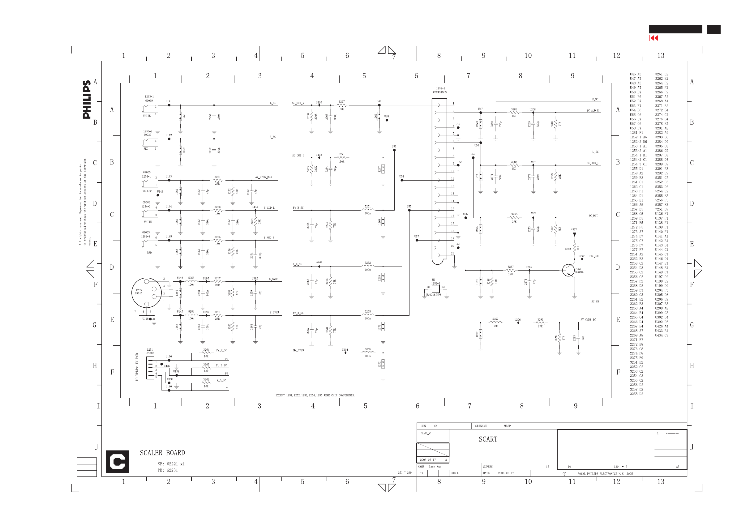
Schematic Diagram of scaler3-for15"&20"
ME5P 15" & 20"
Go to cover page
79
Page 80
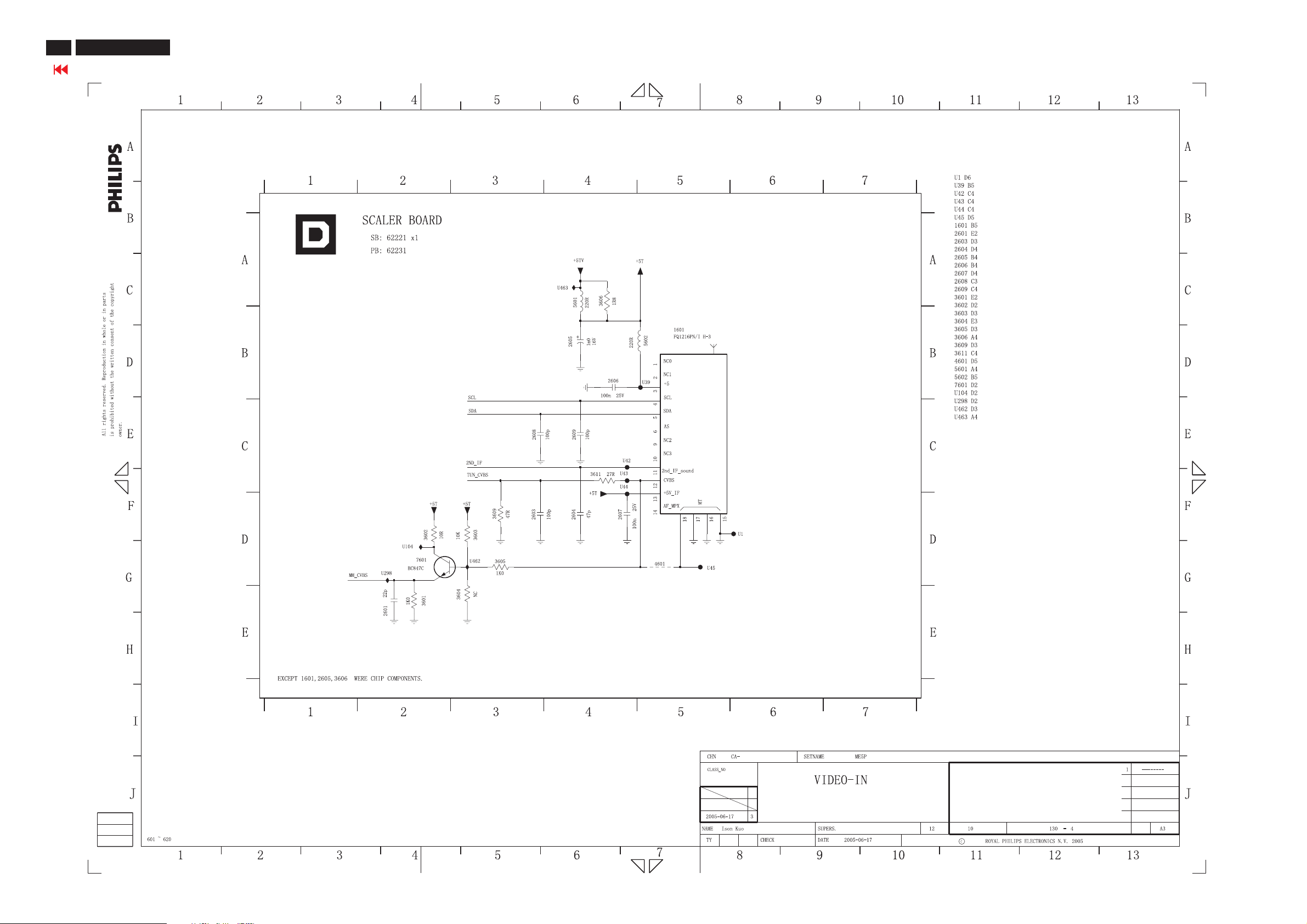
80
ME5P 15" & 20"
Go to cover page
Schematic Diagram of scaler4-for15"&20"
Page 81
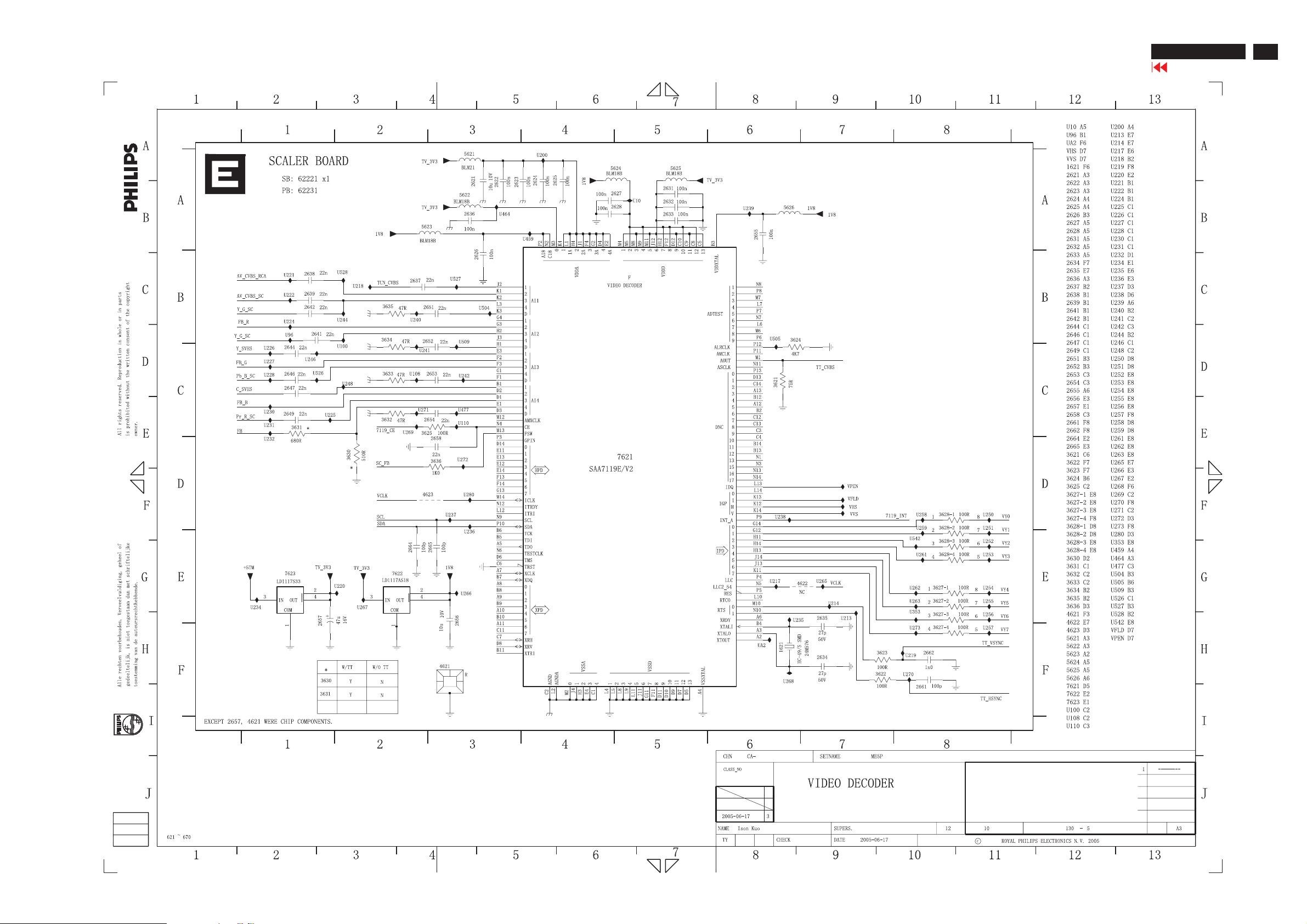
Schematic Diagram of scaler5-for15"&20"
ME5P 15" & 20"
Go to cover page
81
Page 82
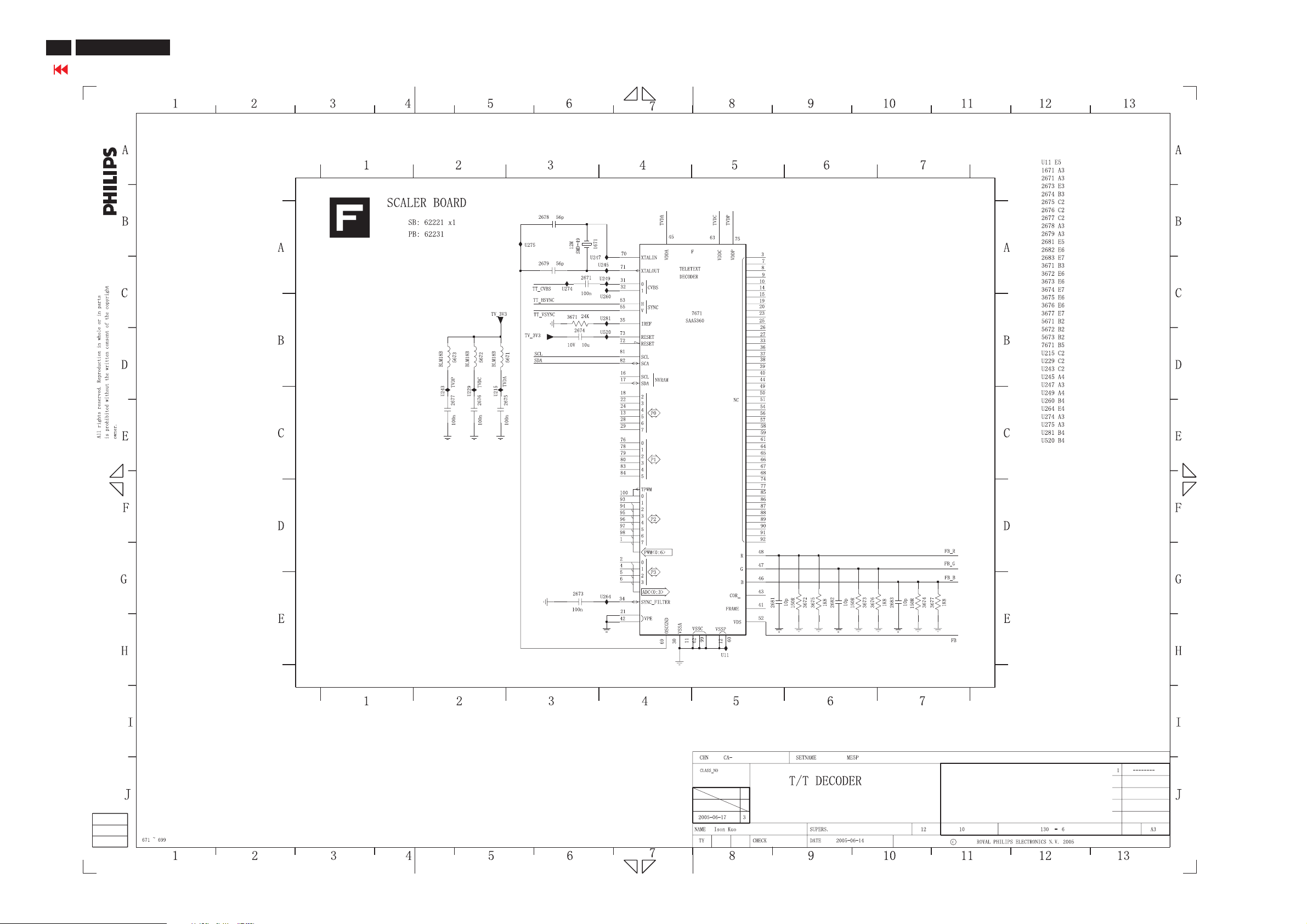
82
ME5P 15" & 20"
Go to cover page
Schematic Diagram of scaler6-for15"&20"
Page 83
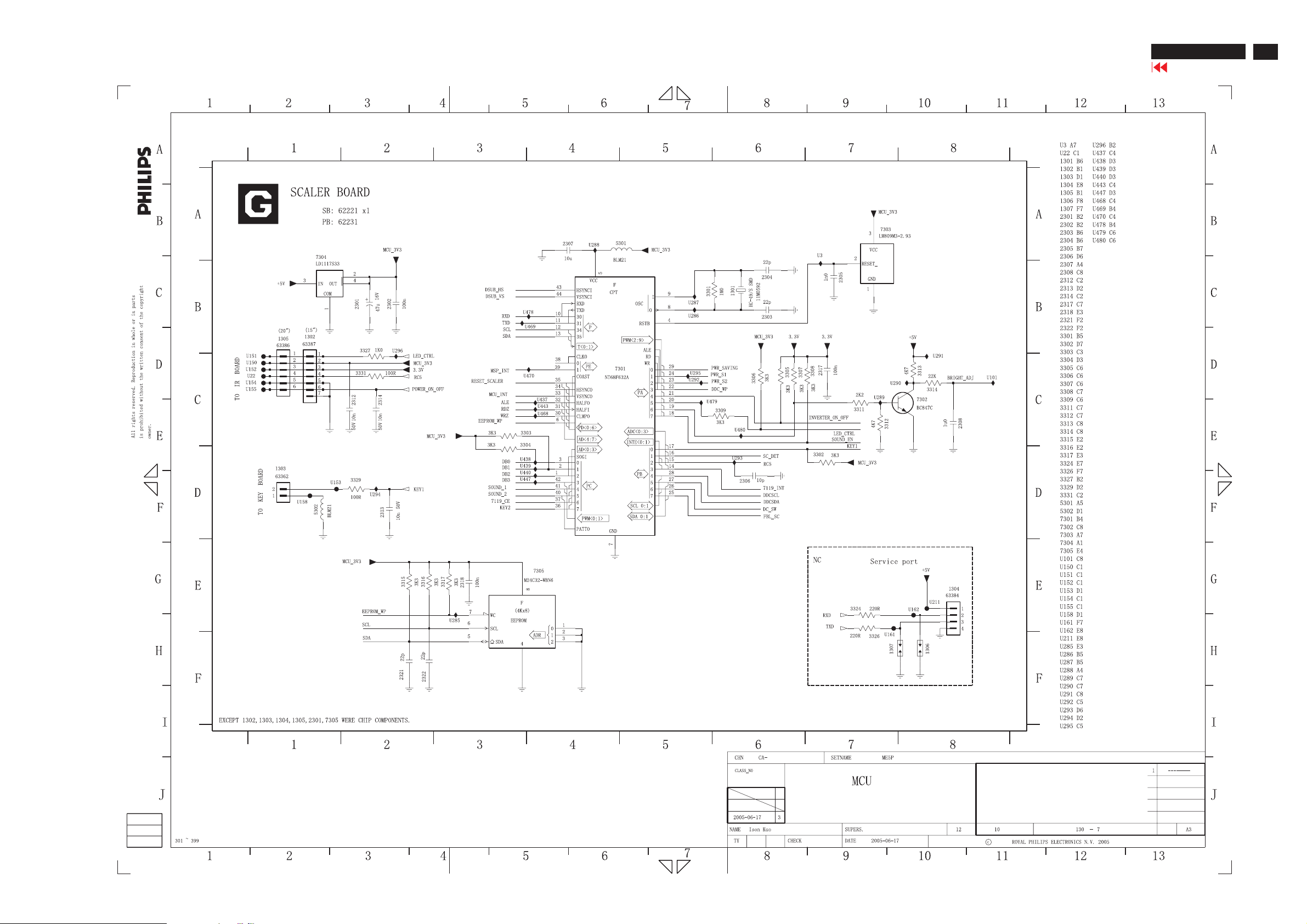
Schematic Diagram of scaler7-for15"&20"
ME5P 15" & 20"
Go to cover page
83
Page 84
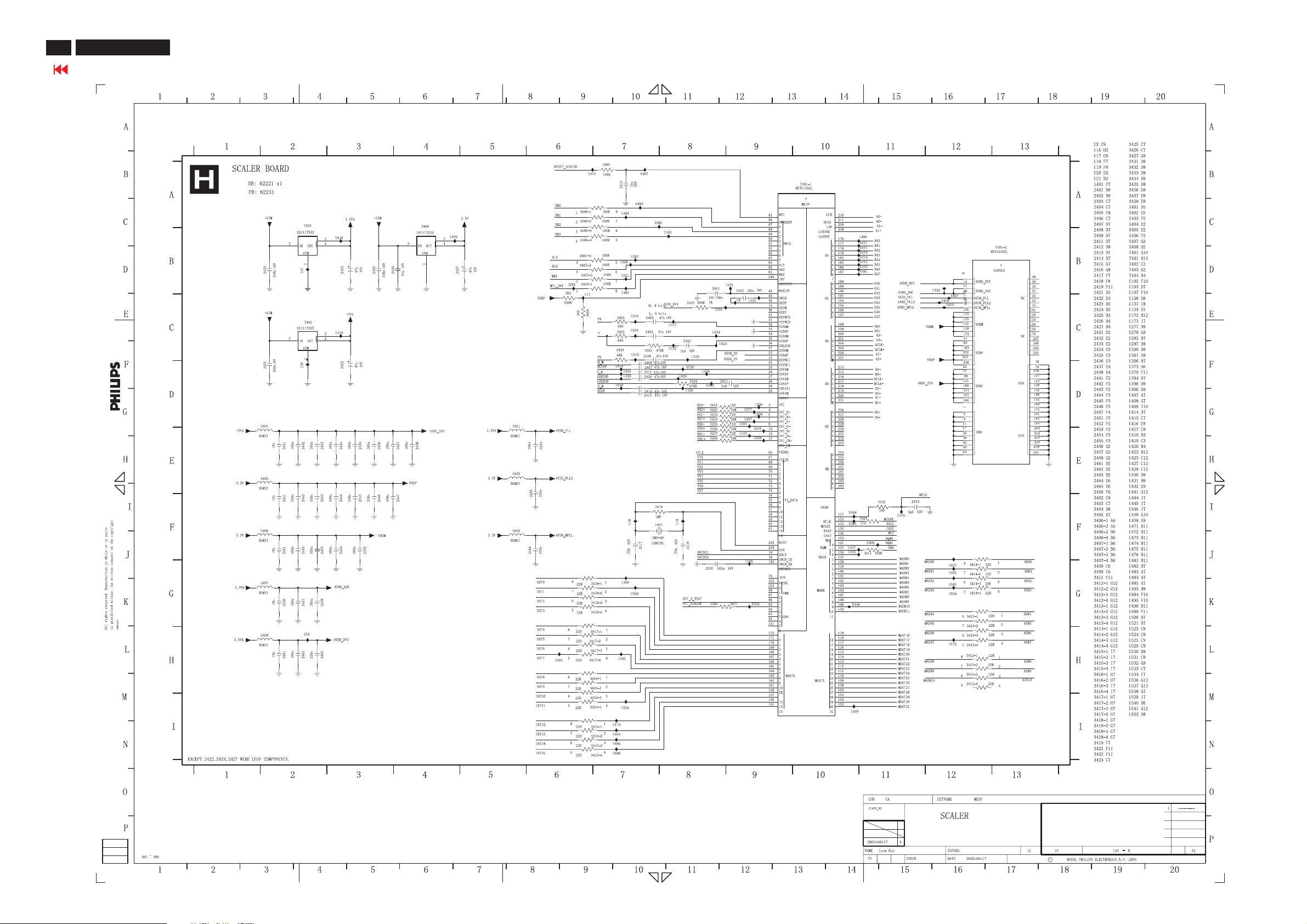
84
ME5P 15" & 20"
Go to cover page
Schematic Diagram of scaler8-for15"&20"
Page 85
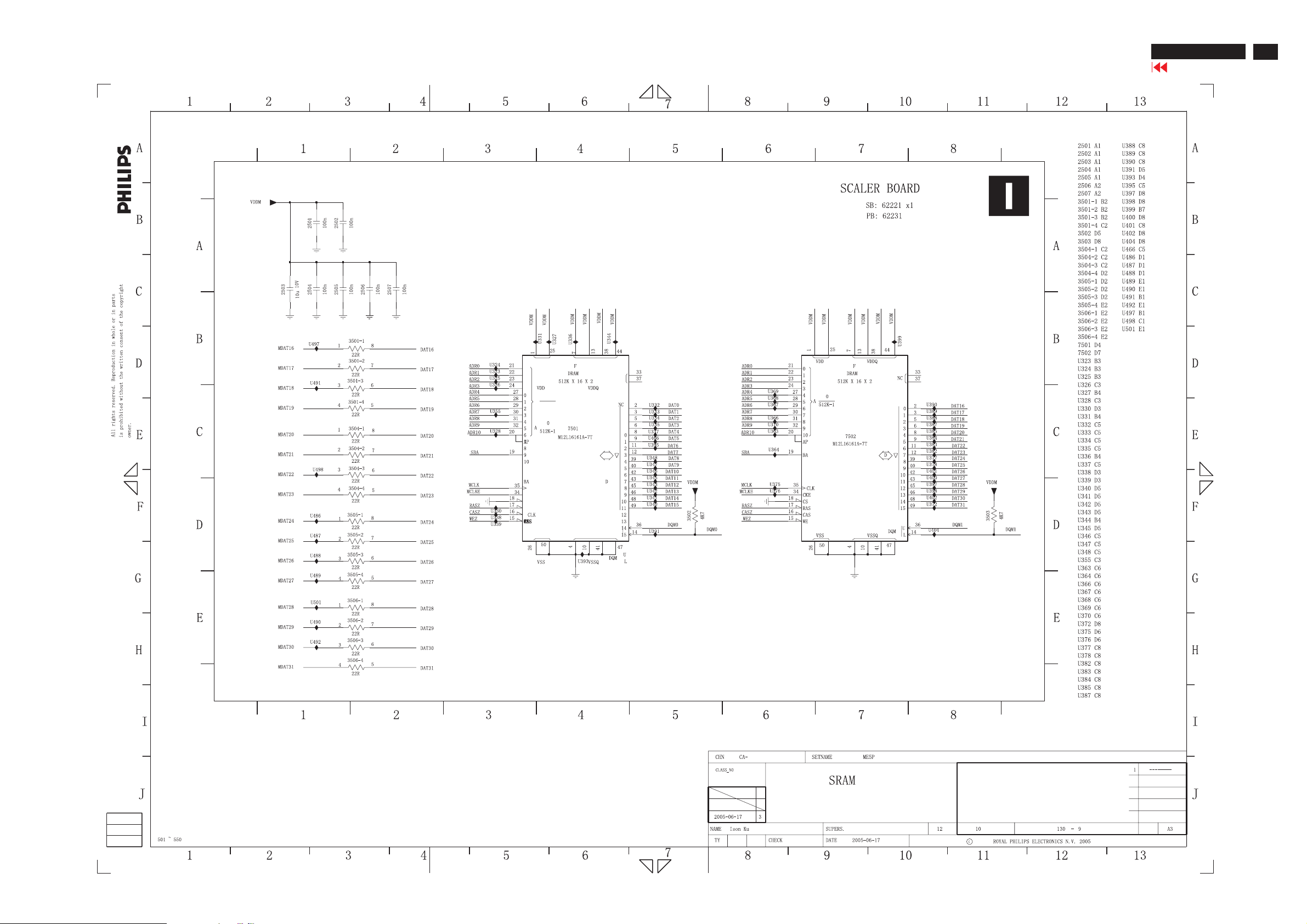
Schematic Diagram of scaler9-for15"&20"
ME5P 15" & 20"
Go to cover page
85
Page 86
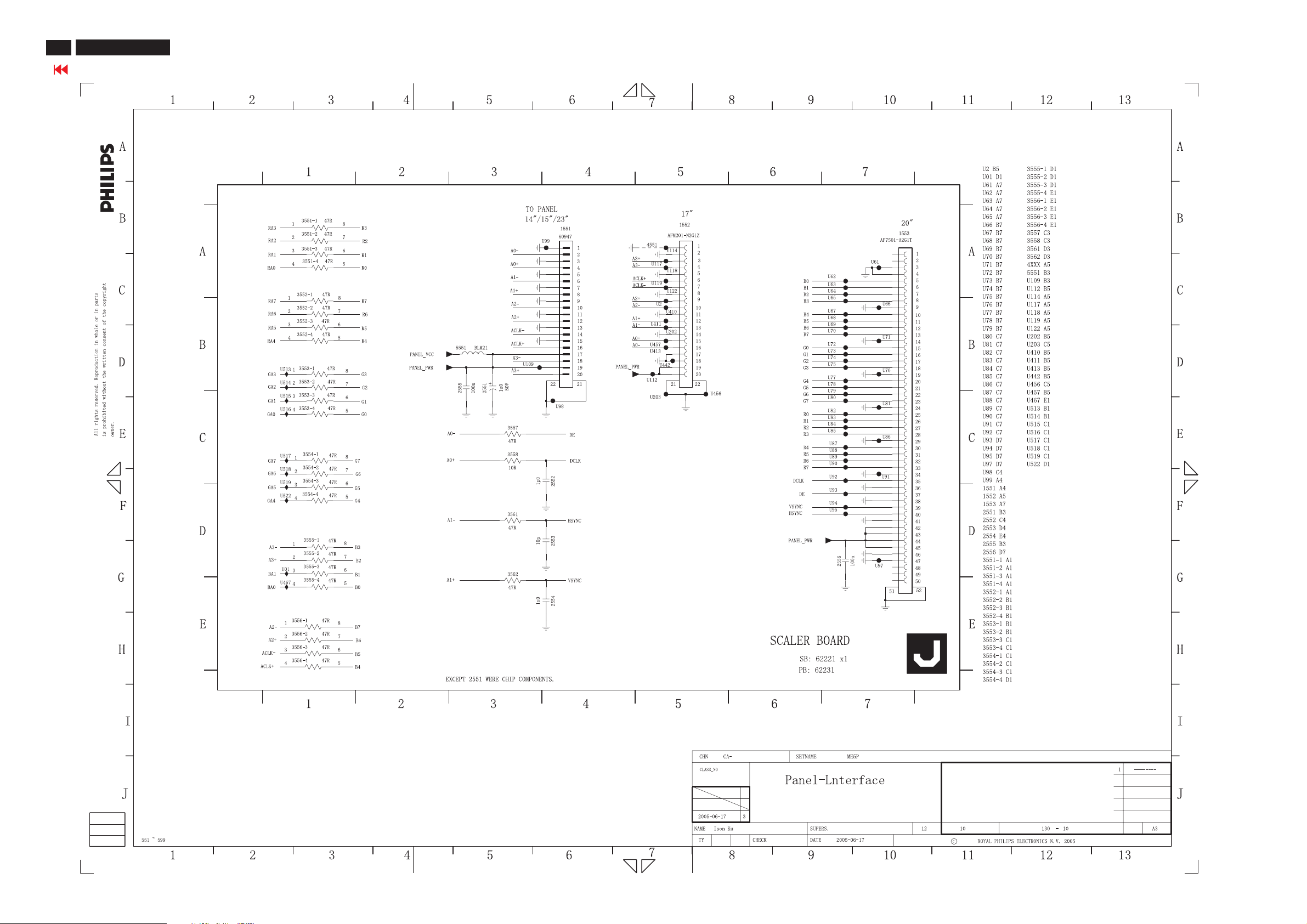
86
ME5P 15" & 20"
Go to cover page
Schematic Diagram of scaler 10 - for 15" & 20"
Page 87
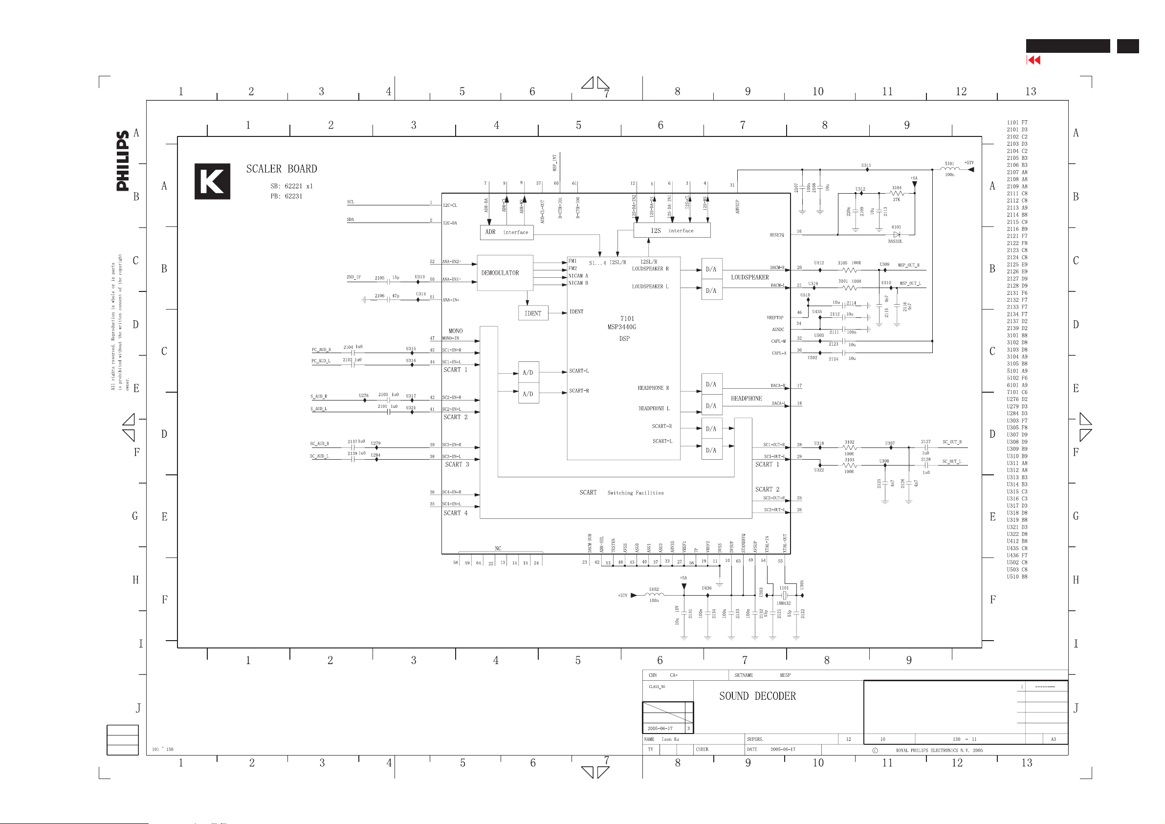
Schematic Diagram of scaler 11 - for 15" & 20"
ME5P 15" & 20"
Go to cover page
87
Page 88
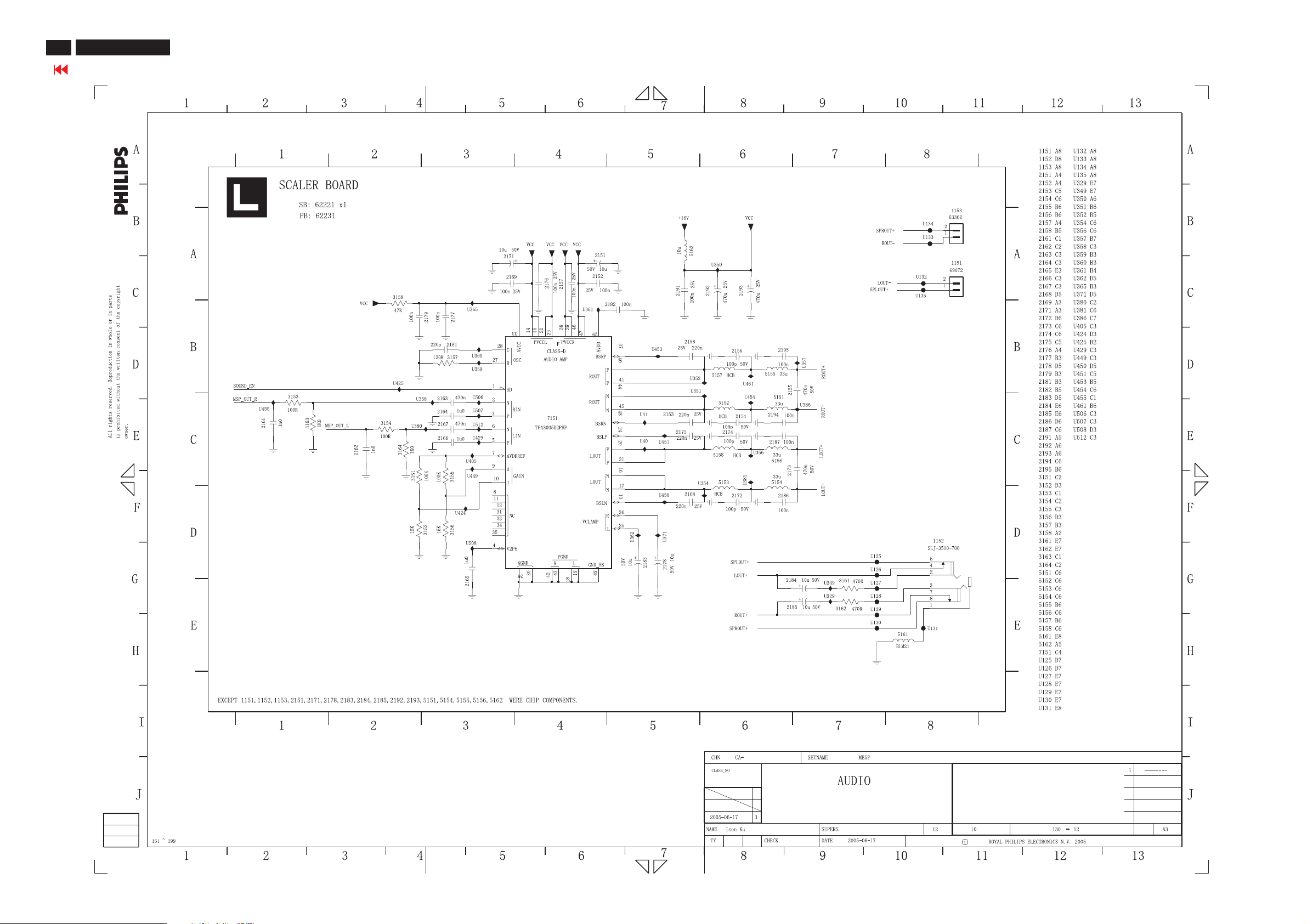
88
ME5P 15" & 20"
Go to cover page
Schematic Diagram of scaler 12 - for 15" & 20"
Page 89
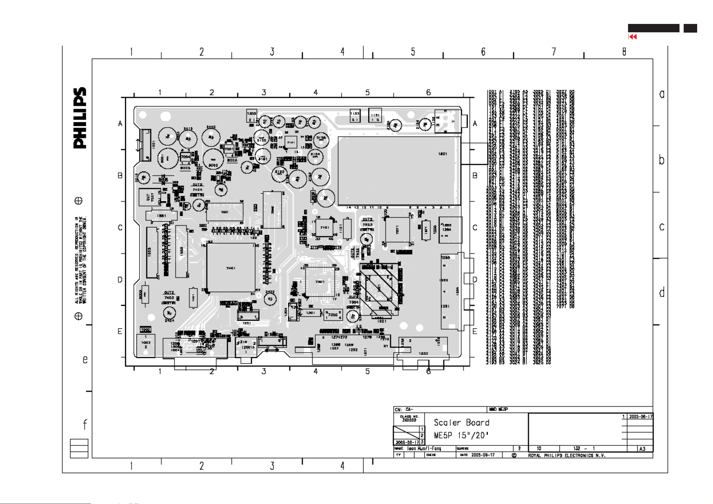
Scaler Board C.B.A1-for15"&20"
ME5P 15" & 20"
Go to cover page
89
Page 90
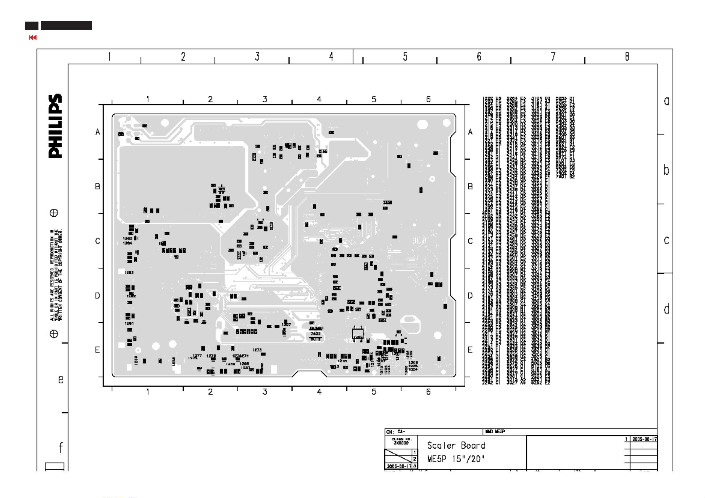
90
ME5P 15" & 20"
Go to cover page
Scaler Board C.B.A2-for15"&20"
Page 91
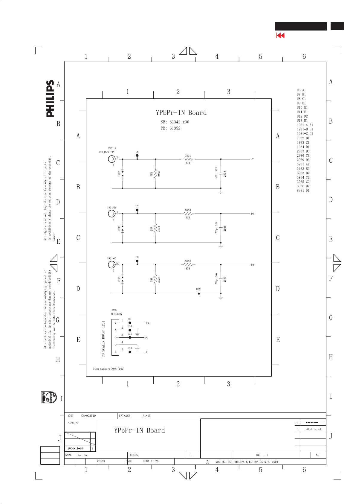
YPbPr-IN PCB Schematic Diagram - For 15" & 20"
ME5P 15" & 20"
Go to cover page
91
Page 92
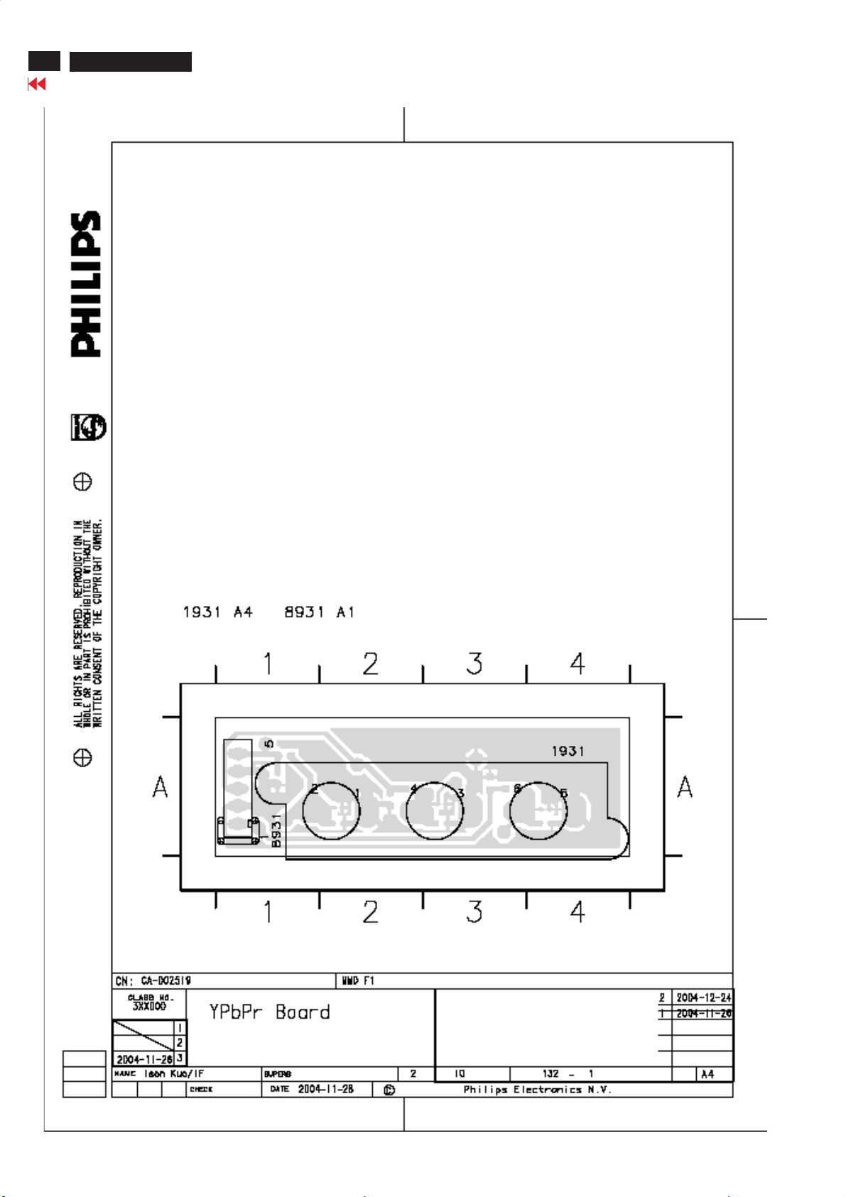
92
ME5P 15" & 20"
Go to cover page
YPbPr-IN PCB C.B.A1-For15"&20"
Page 93
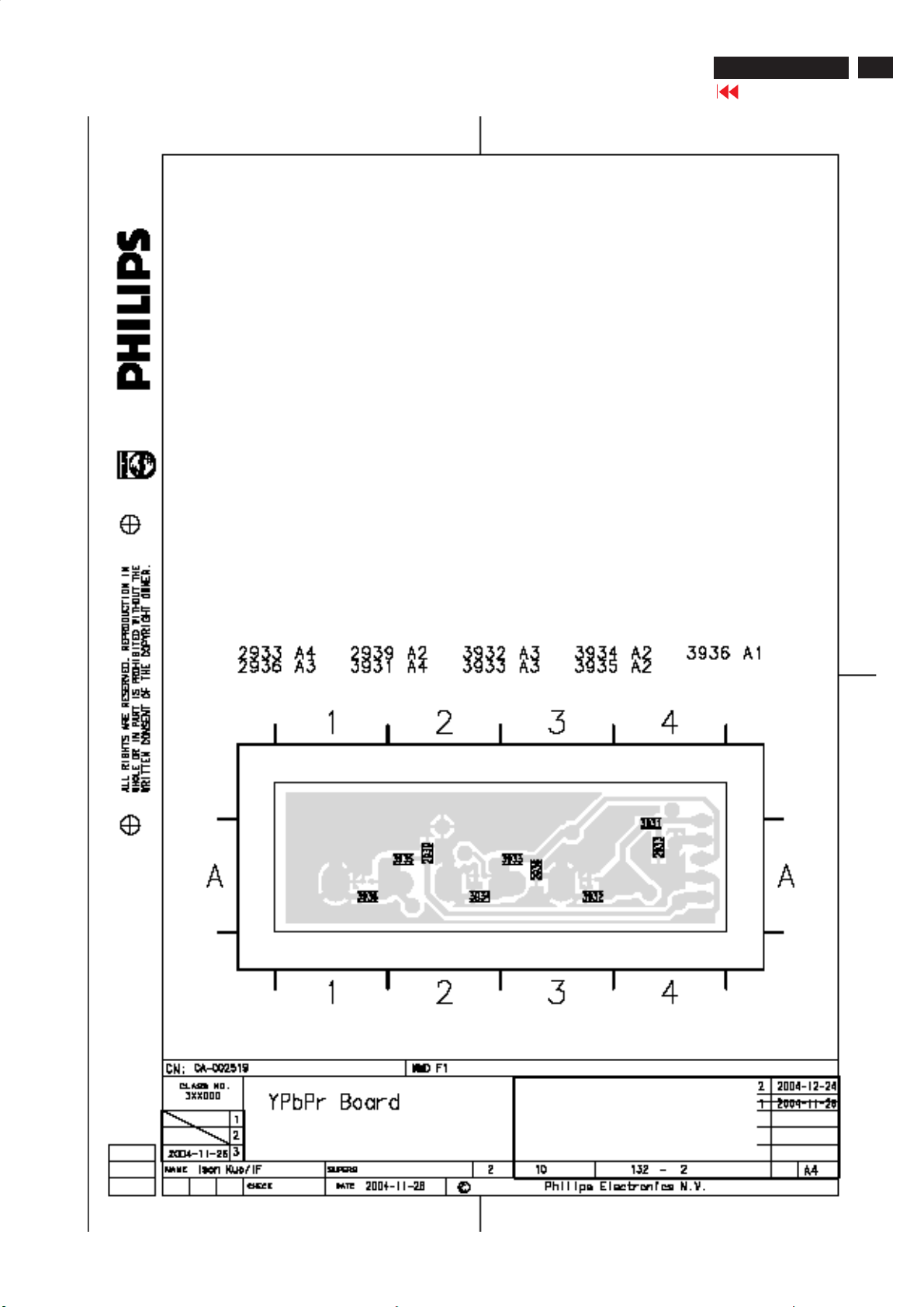
YPbPr-IN PCB C.B.A2-For15"&20"
ME5P 15" & 20"
Go to cover page
93
Page 94
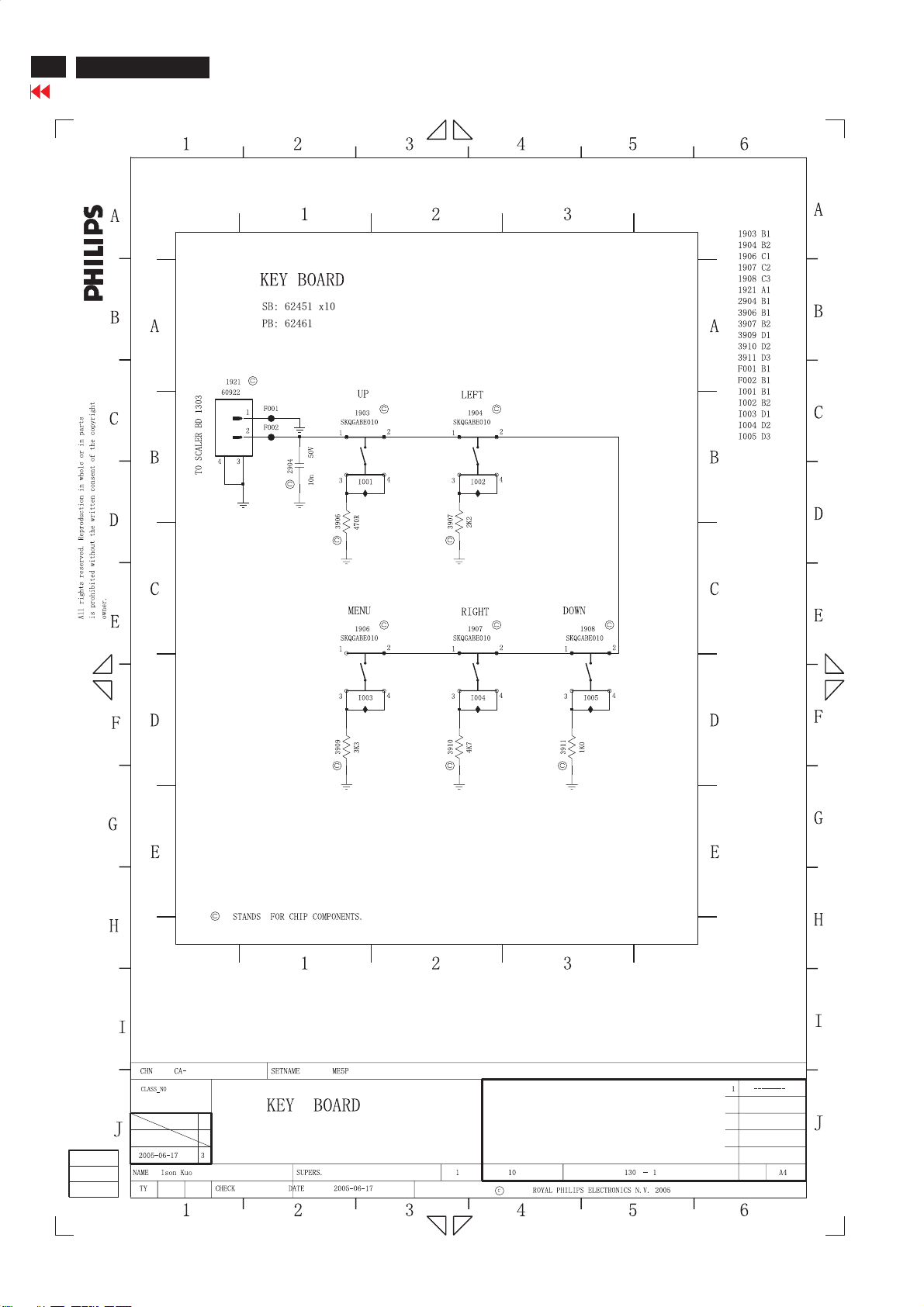
94
ME5P 15" & 20"
Go to cover page
KEY PCB Schematic Diagram - For 15" & 20"
Page 95
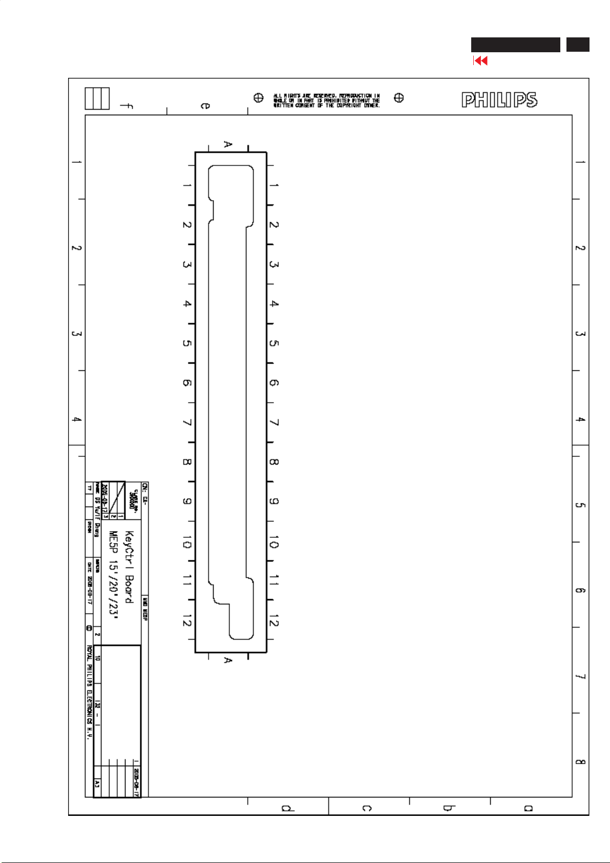
KEYPCBC.B.A1-For15"&20"
ME5P 15" & 20"
Go to cover page
95
Page 96
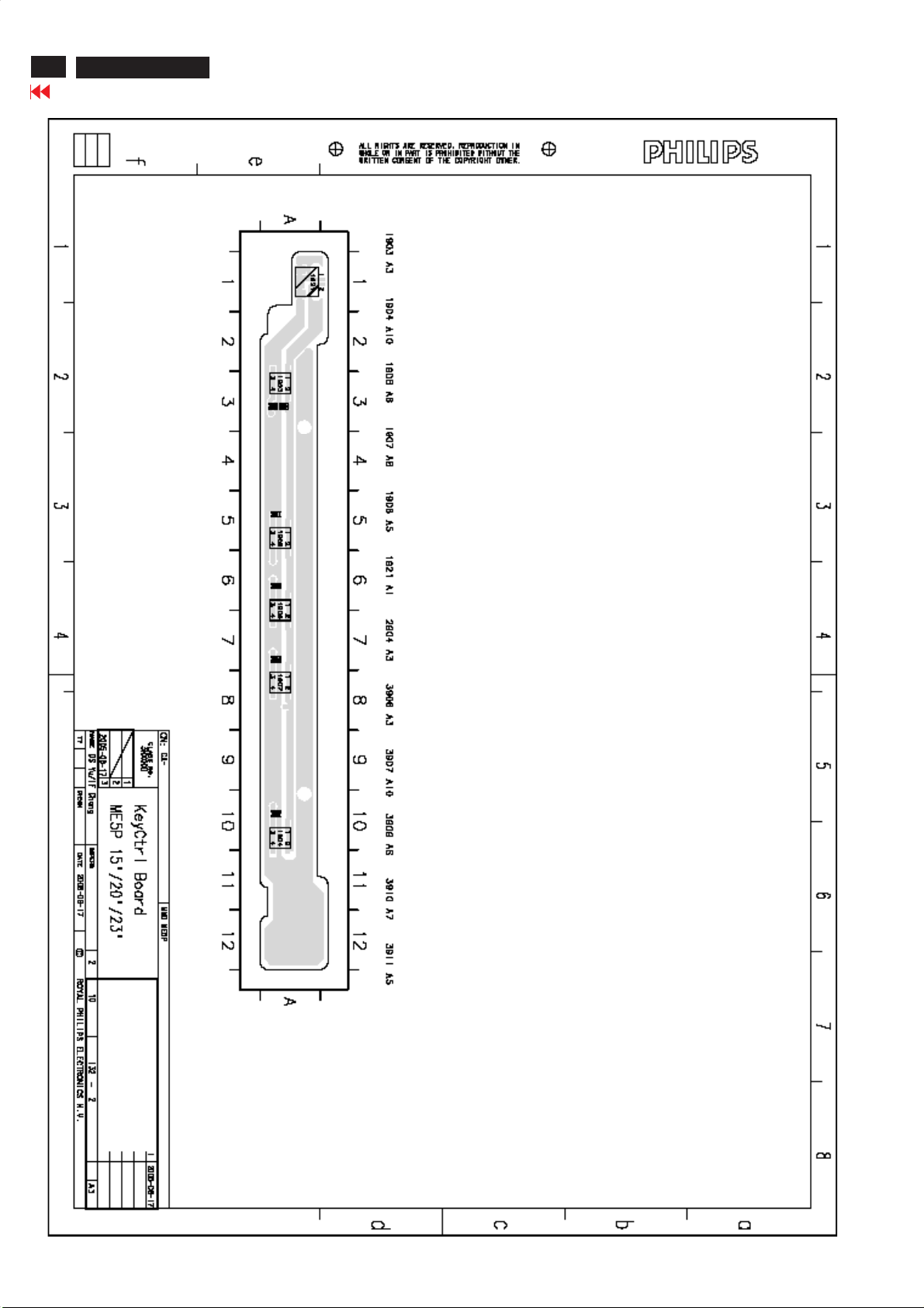
96
ME5P 15" & 20"
Go to cover page
KEYPCBC.B.A2-For15"&20"
Page 97
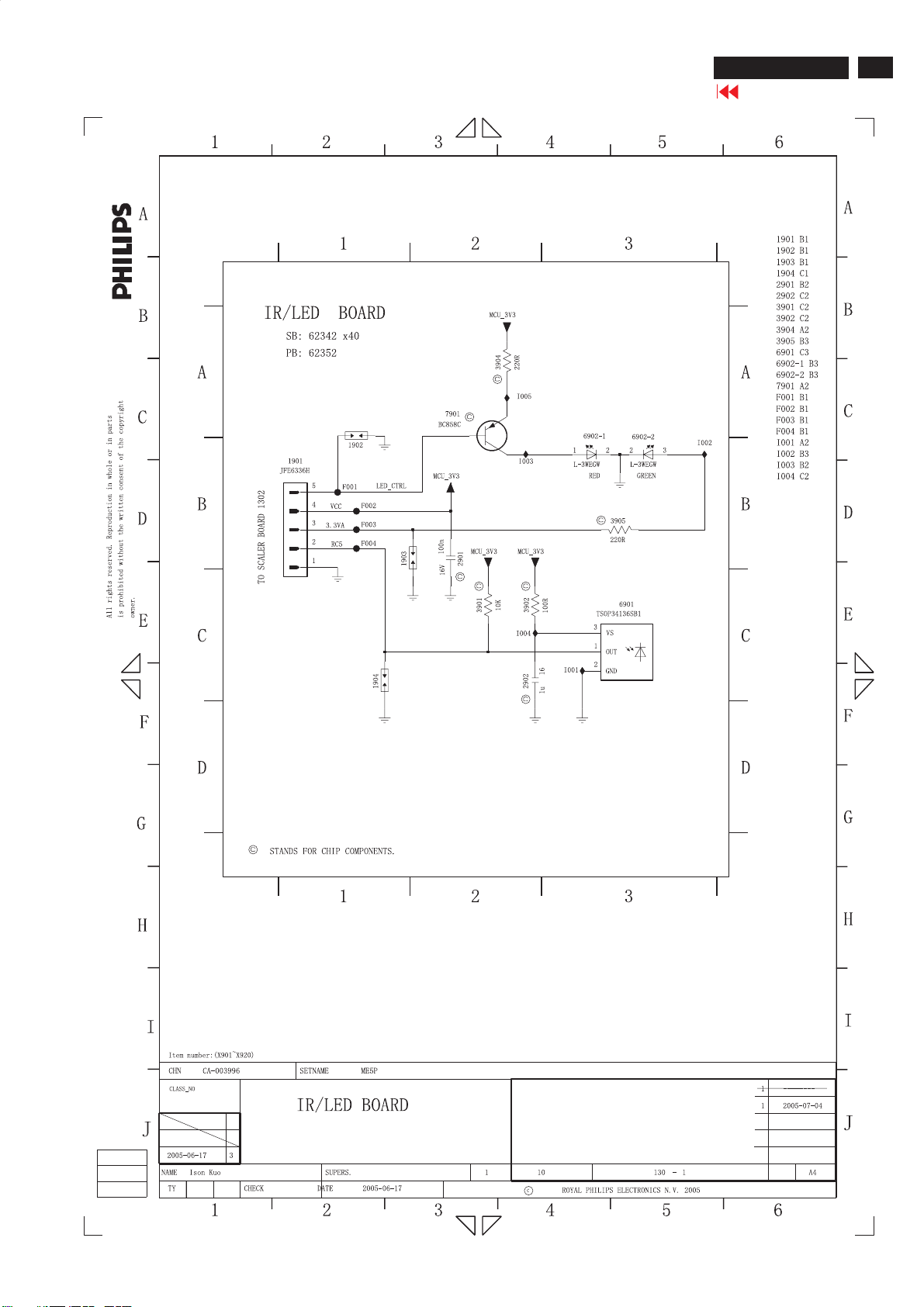
IR/LED PCB Schematic Diagram - Only for 15"
ME5P 15" & 20"
Go to cover page
97
Page 98
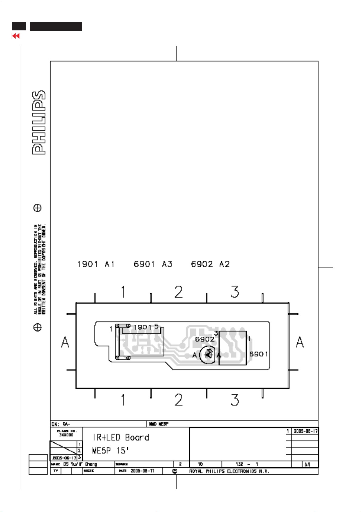
98
ME5P 15" & 20"
Go to cover page
IR/LED PCB C.B.A 1 - Only for 15"
Page 99
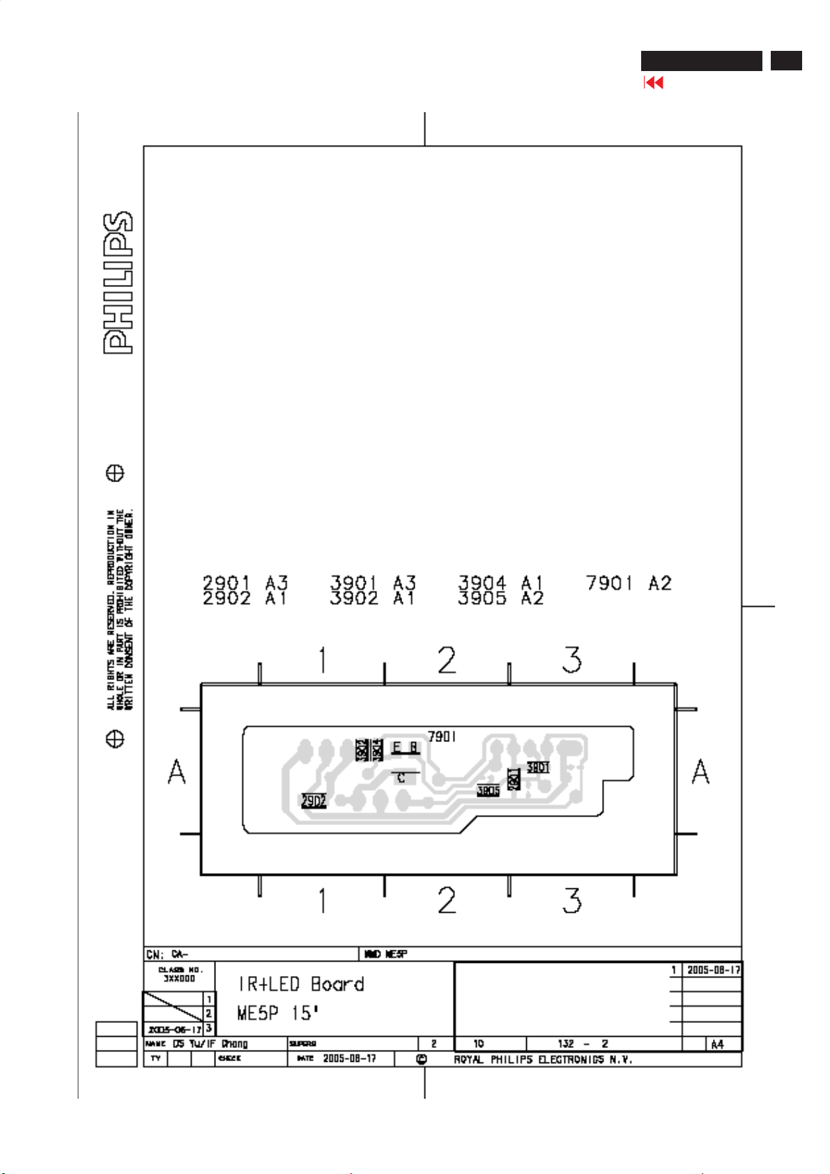
IR/LED PCB C.B.A 2 - Only for 15"
ME5P 15" & 20"
Go to cover page
99
Page 100
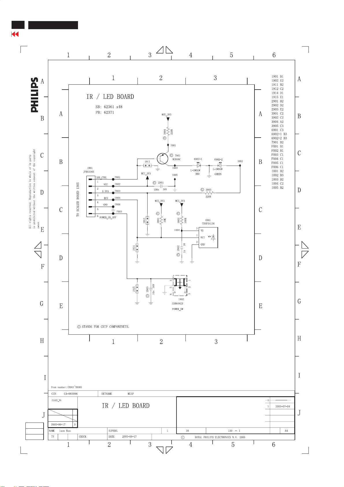
100
ME5P 15" & 20"
Go to cover page
IR/LED PCB Schematic Diagram - Only for 20"
 Loading...