

Page 1

DVD Micro System MCM906
TABLE OF CONTENTS
Location of PC Boards .................................................... 1-1
Specification
Measurement Setup ....................................................... 1-3
Service Aids ................................................................... 1-4
Instruction On CD Playability ..................................1-5 ...1-6
Software Version Check & Upgrade .............................. 2-1
Malfuction Check Chart .................................................. 2-2
Disassembly Diagram ...................................................3-1
Block Diagram ................................................................. 4-1
Wiring Diagram................................................................. 4-2
VFD Display Board .............................................................5
Circuit diagram ........................................................... 5-1
Layout diagram ........................................................... 5-2
Prepositive Board ................................................................6
Circuit diagram ........................................................... 6-1
Layout diagram ........................................................... 6-2
AMP Board ..........................................................................7
Circuit diagram ........................................................... 7-1
Layout diagram ........................................................... 7-2
................................................................. 1-2
2008
Headphone,Button&AUX Board Diagram ...........................8
LAMP Board ....................................................................... 9
TUNER Board ...................................................................10
Circuit diagram ......................................................... 10-1
Layout diagram ......................................................... 10-2
Decoder Board ...................................................................11
Circuit diagram ..............................................11-1 to 11-4
Layout diagram ..............................................11-5 to 11-6
Explode View ................................................................12-1
Service Partlist ....................................................13-1 to 13-2
Factory Partlist ..................................................13-3 to 13-11
DB 0831
3141 785 33070
Page 2
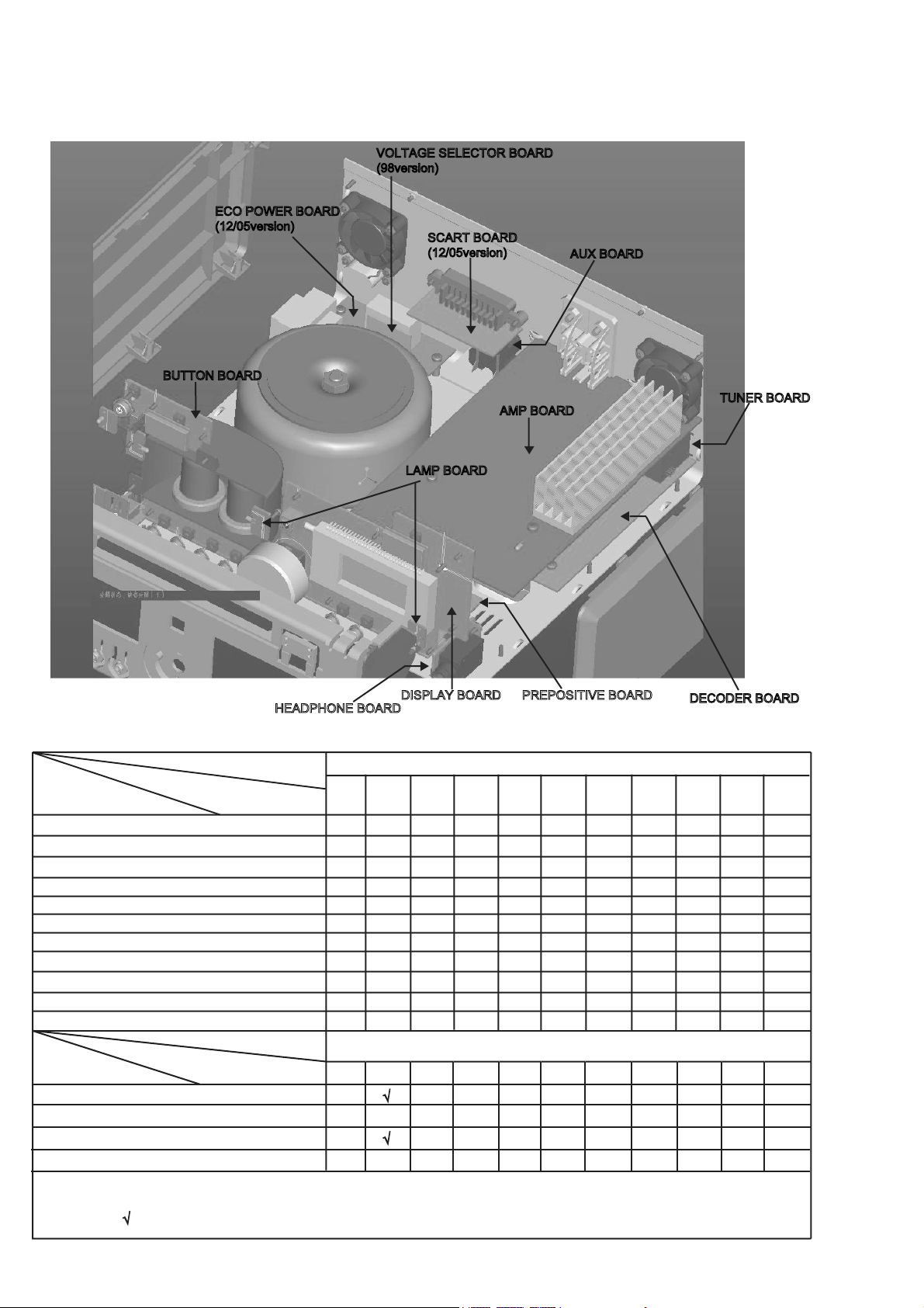
Location of PC Boards
BUTTON BOARD
ECO POWER BOARD
(12/05version)
1-1
VOLTAGE SELECTOR BOARD
(98version)
SCART BOARD
(12/05version)
AMP BOARD
LAMP BOARD
AUX BOARD
TUNER BOARD
VERSION VARIATIONS
:
Type /Versions:
Board in used:
Service policy
BUTTON BOARD
DISPLAY BOARD
AXU BOARD
M-boy BOARD
DECODER BOARD
AMP BOARD
HEADPHONE BOARD
LAMP BOARD
PREPOSITIVE BOARD
ECO-POWER BOARD
Type /Versions:
Features
Feature diffrence
RDS
VOLTAGE SELECTOR
ECO STANDBY - DARK
TDS
* TIPS : C -- Component Lever Repair.
M -- Module Lever Repair
-- Used
HEADPHONE BOARD
/12
/05
M
C
M
M
M
C
M
M
C
M
/12
/05
/37
/37
/55
/55
PREPOSITIVE BOARDDISPLAY BOARD
/58
/58
MCM906
/61
MCM906
/61
/79
/79
DECODER BOARD
/93
/94
/93
/94
/96
/96
/98
/98
Page 3

Specification
1-2
AMPLIFIER
Rated Output Power ............................75W x 2 RMS
Signal-to-noise ratio .................................
Frequency response ......... 40Hz + 3dB+/-3 20KHz
Aux Input ......................................0.5V RMS 47kohm
65 dBA
DISC
Laser Type .......................................... Semiconductor
Disc Diameter ............................................ 12cm/8cm
Support Disc ......................................................MP3,
CD-DA,CD-R,CD-RW
Audio DAC ....................................... 24Bits / 44.1kHz
Total Harmonic Distortion ..................... <0.5%(1kHz)
Frequency Response ..........20Hz + 0.5dB+/-2 20KHz
S/N Ration .................................................... ≥65dBA
TUNER
FM Tuning Range.............................87.5 – 108 MHz
Tuning grid ............................................100K/50KHz
Sensitivity
– Mono, 50dB S/N Ratio ..................................... 5u V
– Stereo, 50dB S/N Ratio ................................ 100uV
Selectivity ........................................................ >33dB
Image Rejection .............................................. >25dB
Total Harmonic Distortion ................................... <1%
Signal to Noise Ration .................................. >65dBA
SPEAKERS
Speaker Impedance ................................................ 4ohm
Speaker Driver, base................................................5 1/4"
Speaker Driver, tweeter ............................................Φ 25
Frequency Response ...................40Hz + 3dB+/-3 20KHz
GENERAL INFORMATION
Total Output power ..................................... 1 5 0 W RMS
AC Power..............................................220-230V / 50Hz
Operation Power Consumption ................................. 85W
Standby Power Consumption .....................................<4W
Eco Standby Power Consumption ..............................<1W
Headphone Output ................................ 2X15mW 32ohm
USB Direct ...................................................... Version 1.1
Dimensions
– Main unit (w x h x d) ............................275x126x250mm
– Speaker box (w x h x d) ....................186x300x222.5mm
Weight
– With Packing ...................................................16.5 KG
– Main Unit .............................................................. 5.0KG
– Speaker box .................................................... . 4.5x2KG
Specifications and external appearance are
subject to change without notice.
Page 4
e
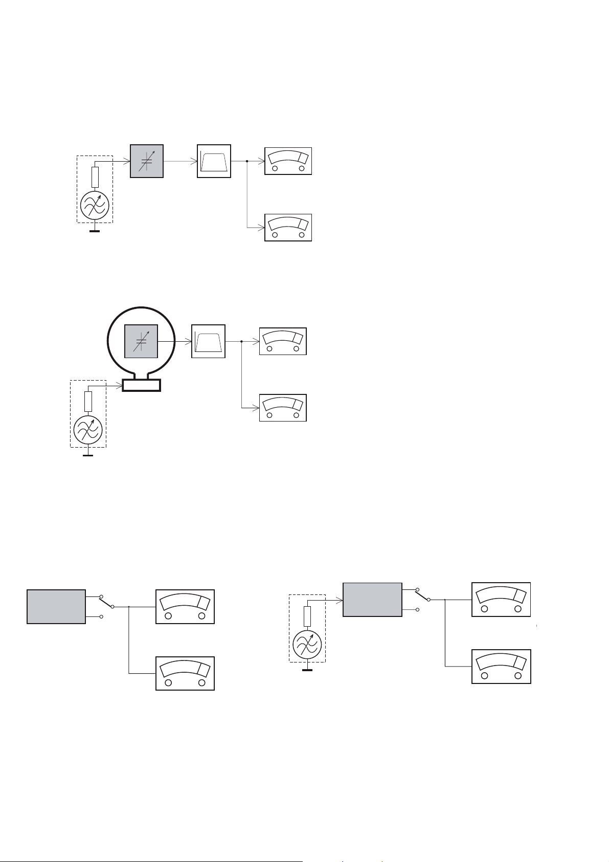
MEASUREMENT SETUP
Tuner FM
1-3
Bandpass
LF Voltmeter
e.g. PM2534
RF Generator
e.g. PM5326
DUT
250Hz-15kHz
e.g. 7122 707 48001
Ri=50:
S/N and distortion meter
e.g. Sound Technology ST1700B
Use a bandpass filter to eliminate hum (50Hz, 100Hz) and disturbance from the pilottone (19kHz, 38kHz).
Tuner AM (MW,LW)
RF Generator
e.g. PM5326
Ri=50:
DUT
Frame aerial
e.g. 7122 707 89001
Bandpass
250Hz-15kHz
e.g. 7122 707 48001
LF Voltmeter
e.g. PM2534
S/N and distortion meter
e.g. Sound Technology ST1700B
To avoid atmospheric interference all AM-measurements have to be carried out in a Faraday´s cage.
Use a bandpass filter (or at least a high pass filter with 250Hz) to eliminate hum (50Hz, 100Hz).
CD
Use Audio Signal Disc
(replaces test disc 3)
DUT
L
R
SBC429 4822 397 30184
S/N and distortion meter
e.g. Sound Technology ST1700B
LEVEL METER
e.g. Sennheiser UPM550
-
Recorder
Use Universal Test Cassette CrO2 SBC419 4822 397 30069
or Universal Test Cassette
LF Generator
e.g. PM5110
Fe SBC420 4822 397 30071
DUT
L
R
S/N and distortion met
e.g. Sound Technology ST170
LEVEL METER
e.g. Sennheiser UPM550
with FF-filter
Page 5
SERVICE AIDS
1-4
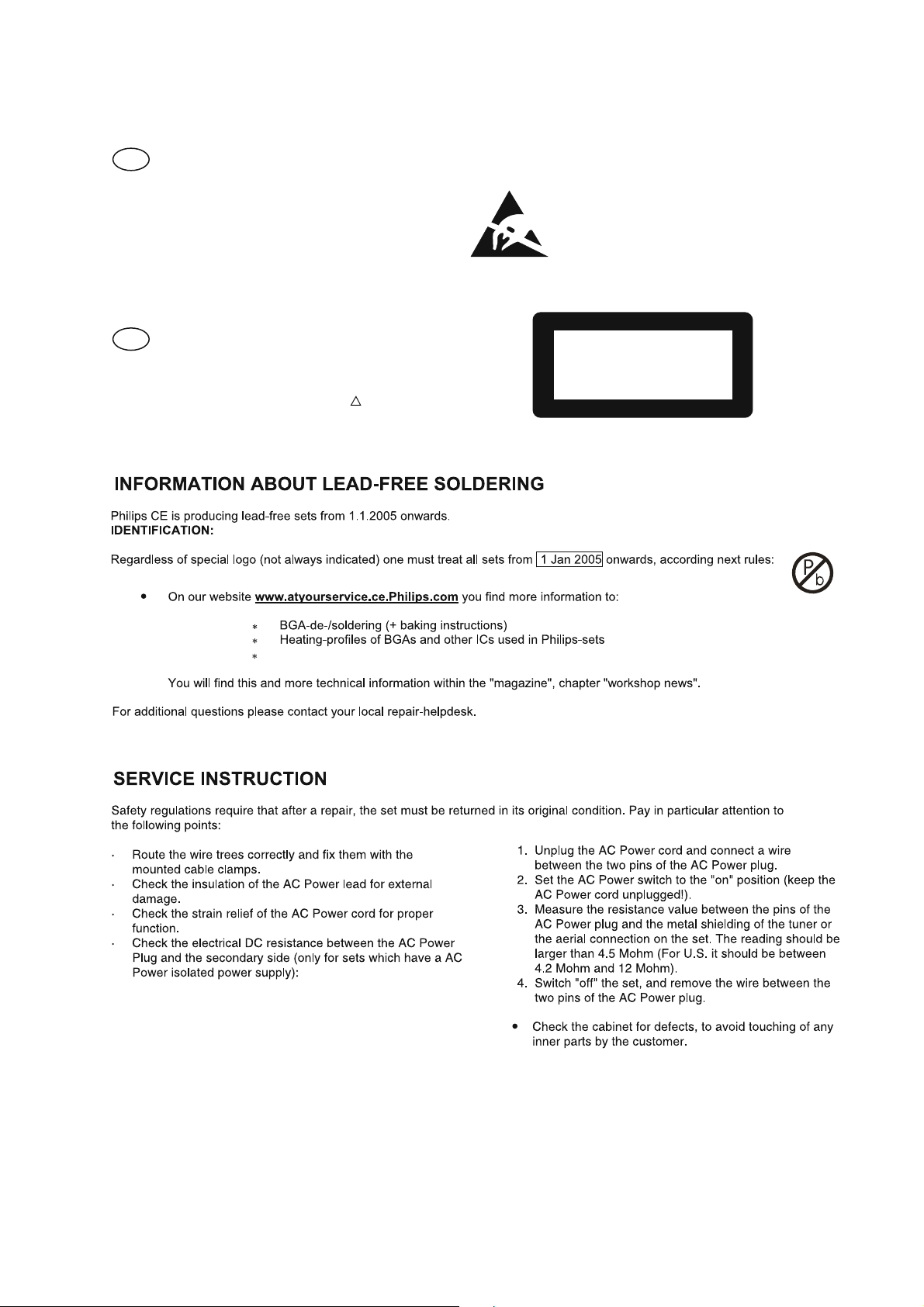
GB
All ICs and many other semi-conductors are
susceptible to electrostatic discharges (ESD).
Careless handling during repair can reduce life
drastically.
When repairing, make sure that you are
connected with the same potential as the mass
of the set via a wrist wrap with resistance.
Keep components and tools also at this
potential.
WARNING
GB
Safety regulations require that the set be restored to its original
condition and that parts which are identical with those specified,
be used
Safety components are marked by the symbol
!
.
ESD
CLASS 1
LASER PRODUCT
Lead free
Page 6
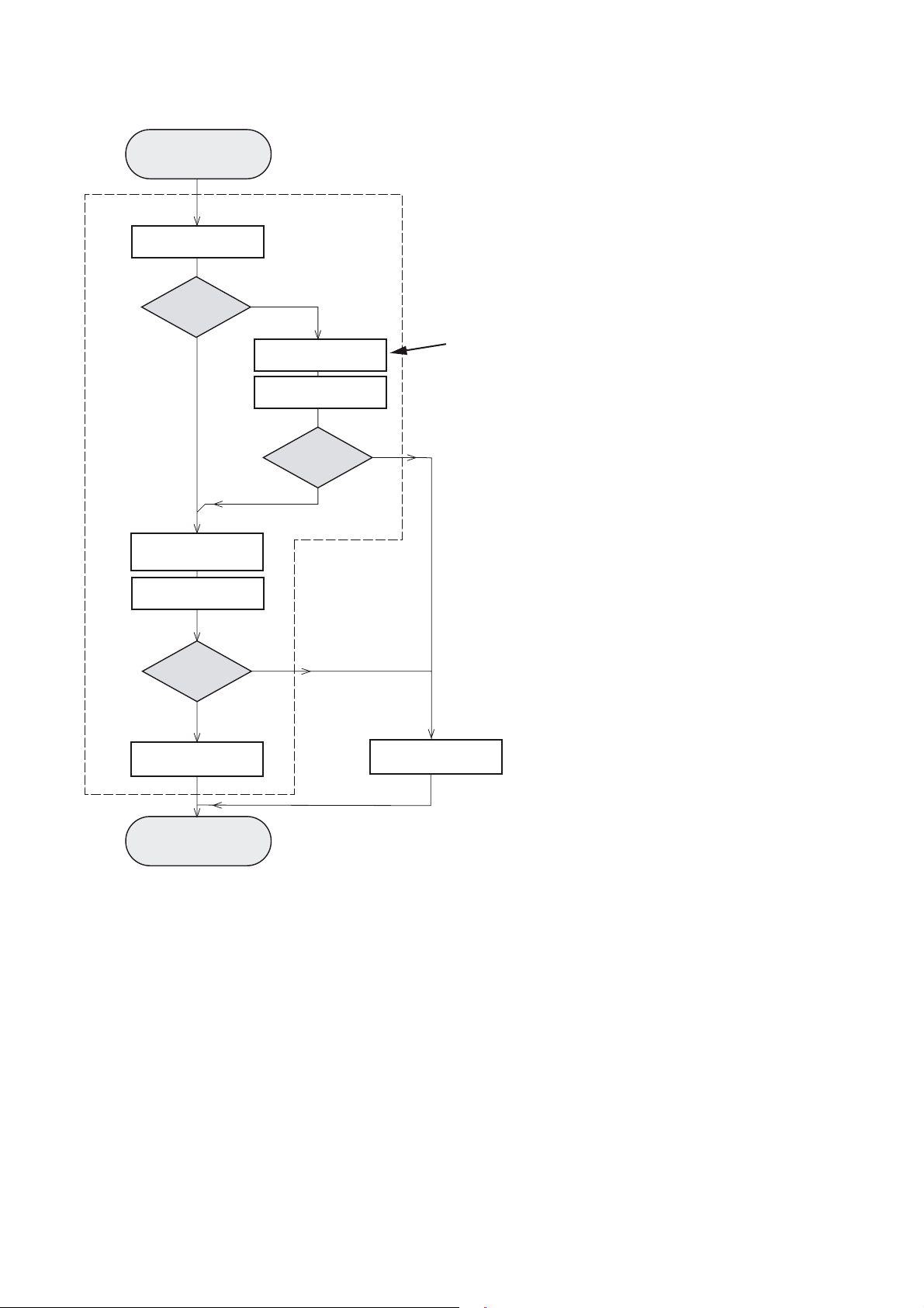
INSTRUCTIONS ON CD PLAYABILITY
Customer complaint
"CD related problem"
Set remains closed!
check playability
1
1-
playability
ok ?
Y
Play a CD
for at least 10 minutes
check playability
playability
ok ?
Y
N
"fast" lens cleaning
check playability
playability
ok ?
N
3
N
Y
For flap loaders (= access to CD drive possible)
cleaning method
4 is recommended
add Info for customer
"SET OK"
2
return set
1 - 4 For description - see following pages
Exchange CDM
Page 7
INSTRUCTIONS ON CD PLAYABILITY
1-
1
PLAYABILITY CHECK
For sets which are compatible with CD-RW discs
use CD-RW Printed Audio Disc ....................7104 099 96611
TR 3 (Fingerprint)
TR 8 (600μ Black dot) maximum at 01:00
• playback of these two tracks without audible disturbance
playing time for: Fingerprint t10seconds
Black dot from 00:50 to 01:10
• jump forward/backward (search) within a reasonable time
For all other sets
use CD-DA SBC 444A..................................4822 397 30245
TR 14 (600μ Black dot) maximum at 01:15
TR 19 (Fingerprint)
TR 10 (1000μ wedge)
• playback of all these tracks without audible disturbance
playing time for: 1000μ wedge t10seconds
Fingerprint t10seconds
Black dot from 01:05 to 01:25
• jump forward/backward (search) within a reasonable time
4
LIQUID LENS CLEANING
Before touching the lens it is advised to clean the
surface of the lens by blowing clean air over it.
This to avoid that little particles make scratches on
the lens.
Because the material of the lens is synthetic and coated
with a special anti-reflectivity layer, cleaning must be done
with a non-aggressive cleaning fluid. It is advised to use
“Cleaning Solvent
The actuator is a very precise mechanical component and
may not be damaged in order to guarantee its full function.
Clean the lens gently (don’t press too hard) with a soft and
clean cotton bud moistened with the special lens cleaner.
The direction of cleaning must be in the way as indicated in
the picture below.
2
CUSTOMER INFORMATION
It is proposed to add an addendum sheet to the set which
informs the customer that the set has been checked
carefully - but no fault was found.
The problem was obviously caused by a scratched, dirty or
copy-protected CD. In case problems remain, the customer
is requested to contact the workshop directly.
The lens cleaning (method 3) should be mentioned in the
addendum sheet.
The final wording in national language as well as the printing
is under responsibility of the Regional Service Organizations.
Page 8

Software Version Check & Upgrade
Upgrade software
1.Downloading the software form Philips support website
http://www.philips.com/support
2.Put in the Software CD Disc or USB,when it is loading
Waiting a minute,till hear a long ding voice. Software
upgrade finish.
Software check
Press the “display” button quartic continuously on remote control,
display showing as below:
Vxx dyyyy
2-1
Page 9
Malfunction follow check chart
2-2
Page 10
Disassembly Diagram
3-1
-1
A,Loosen screws as below sketch map to
open the top cabinet:
1,screws:3x6BMTT(3PCS)
2,screws:3x6FMTT(2PCS)
1
2
E,Loosen screws as below sketch map to
remove the Decoder Board:
1,screws:3x10PA(1PCS)
2,screws:3x6BM(2PCS)
3,screws:3X6PMTT(1pc)
B,Loosen screws as below sketch map to
remove the both sides panels:
1,screws:3x6PA(6PCS)
2,screws:3x10PA(2PCS)
1
2
C,Loosen screws as below sketch map to
remove the DVD mechanism bracket:
1,screws:3x12BA(2PCS)
2,after loosed the screws, push the DVD mechanism
bracket breadthwise to remove it
1
Aluminium Top Cover
DVD mechanism bracket
F,Loosen screws as below sketch map to
remove the Prepositive Board:
1,screws:3x6PA(2PCS)
D,Loosen screws as below sketch map to
remove AMP board:
1,screws:3x10PA(1PC)
2,screws:3x10PA(4PCS)
1
2
G,Loosen screws as below sketch map to
remove the Display Board:
1,screws:2.6x6BB(10PCS)
3
H,Loosen screws as below sketch map to
remove the USB Board:
1,screws:3x6PA(1PC)
1
1
1
2
I,Loosen screws as below sketch map to
remove the LAMP Board:
1,screws:2.6x4BB(2PCS)
1
1
Page 11
Block Diagram
4-1
4-1
AUX1
AUX2
IC:TEA5766
AUX1 IN
AUX2 IN
TUNER
BLOCK
J8
TUNER-RIN
TUNER-LIN
CD5V
CD DECODE
Decoder
Board
BLOCK
D-FL
D-FR
CD
MECHANISM
REM-SENSOR
REM1GND2Vcc
3
D-FR
D-FL
AUX1 IN
AUX2 IN
TUNER-RIN
TUNER-LIN
SDA
SCL
CPU5V
+12V
VFD701
PT16311
IC201
CPU
9228
U8
PT2314
U12
VFD
24C02
STANDBY
U6
CPU5V
MUTE
STANDBY
CPU5V
FL
FR
KEY
CONTROL
FL
FR
AMP Board
TL027
IC1
FR
FL
12AX7
Q1 / Q2
VFD Board
+vs
-vs
-vs
+vs
FL
TDA8920
FR
IC300
Prepositive
Board
7812
U1
FRONT
SELENIUM
FILTER
CD5V
CPU5V
FM+5V
CES2307
DVD POWER
SWITCH
CONTROL
POWER
SWITCH
CONTROL
AOZ1212
CD ON/OFF
-vs
+vs
AMP
SELENIUM
FILTER
DVD
SELENIUM
FILTER
POWER
SWITCH POWER
AC
Page 12
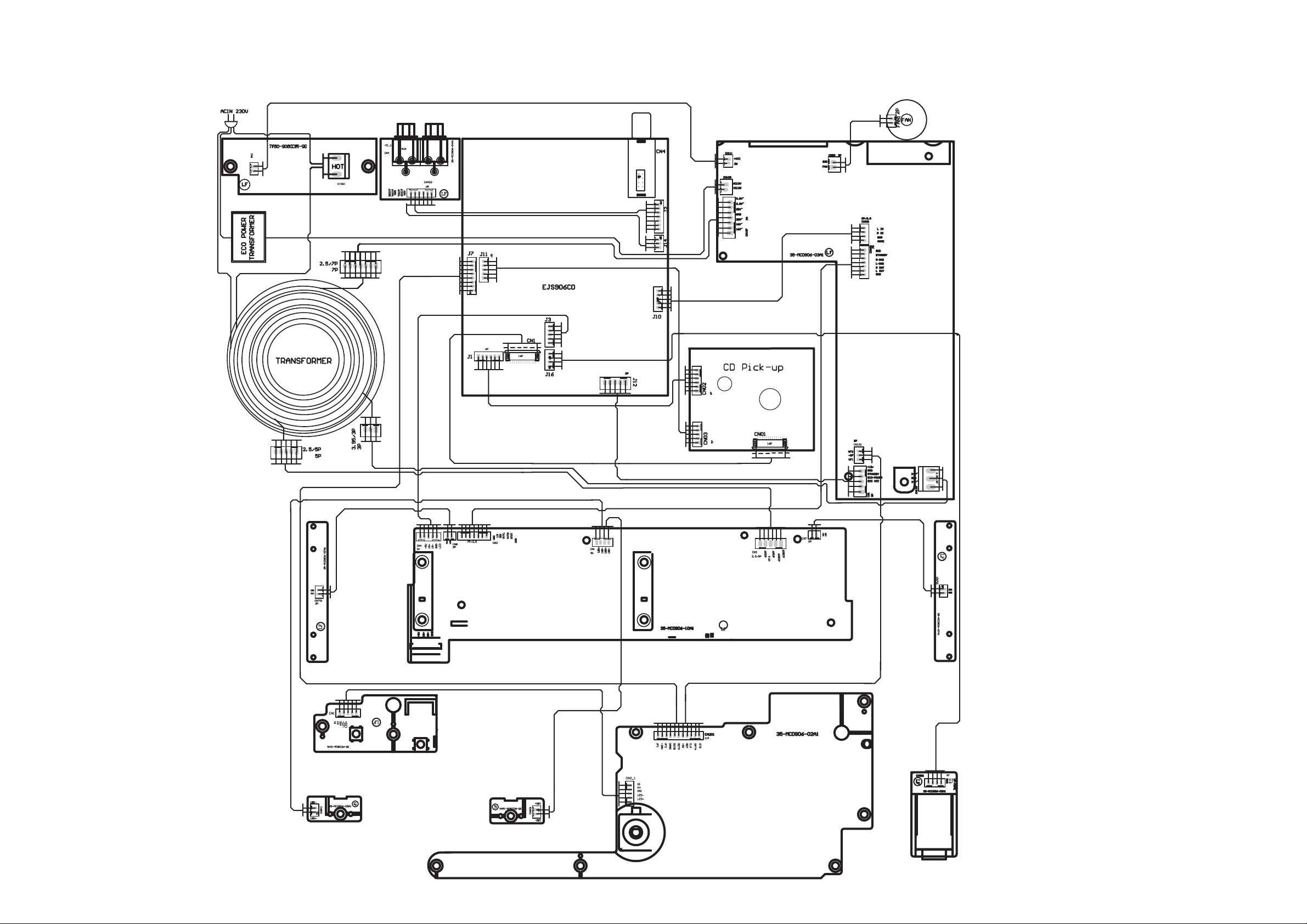
Wiring Diagram
4-24-2
Page 13
5-1 5-1
VFD Display Board --Circuit Diagram
VFD201
MCD190VFD
CORD201
CORD
190-2
R202
4.7/0.5
C202
104
VF11VF12S13S24S35S46S57S68S79S810S911S1012S1113S1214S1315S1416S1517S1618S1719G120G721G822G923G1024G1125G326G227G428G529G630VF231VF2
S1
S2
G1G2G3G4G5
+5V
LED
R209
47K
C207
S4S5S6S7S8S9S10
S3
40
41
42
43
44
45
46
47
48
49
50
51
52
G5
G4
G3
G2
G1
Vdd
LED5
LED4(BBE)
LED3(POWER)
LED2(FANCT)
LED1(7507RST)
Vss
OSC
G6G7G8
37
38
39
G7
G6
S11
G9
36
G8
S20/G9
uPD16311
S12
G10
35
S19/G10
IC201
S13
34
VEE
-28V
33
S16
S17/G12
S17
S16
30
G1
G7
G8G9G10
S13
S14
S15
S1327S1428S1529S16
S12/KS12
S11/KS11
S14
S15
S17
G11
31
32
Vdd
S18/G11
S10/KS10
S9/KS9
S8/KS8
S7/KS7
S6/KS6
S5/KS5
S4/KS4
S3/KS3
S2/KS2
S1/KS1
Vdd
G11
26
25
24
23
22
21
20
19
18
17
16
15
14
G2G3G4G5G6
S12
S11
S10
S9
S8
S7
S6
S5
S4
S3
S2
S1
SW11SW22SW33SW44DOUT5DIN6IC7CLK8STB9KEY110KEY211KEY312KEY4
47uF
13
C208
104
32
R201
4.7/0.5
S4
PLAY
S2
D201
4148
D202
S3 KS3
4148
D203
S1
4148
C201
K4
K3
K2
K1
104
SW212
KS2
KS1
S201
REMOTE
SW201
CH-
R206
10
SW202
STOP
SW203
CH+
REM1GND2Vcc
3
S-BASS
SW205
MODE
SW204
TU+/PREV
SW210
DSC
P-EQ
C205
104
TU-/NEXT
R207
47
C206
47u
SW206
OPEN/CLOCS
SW207
G1B2A
3
VF2
-28V
VF1
V-GND
RT-B
RT-A
+5V
REM
CLK
DATA
STB1
RT-B
RT-A
C203
103
CN201
1
2
3
4
5
6
7
8
9
10
11
11P
C204
103
R211
10K
R212
4.7K
R213
10K
STB1
CLK
DATA
33K
R214
R215 33K
R216 33K
R217 33K
R01 4.7K
K1
K4
KS1
LED
LED++5V
CN2
1
2
3
4
5
5P
Page 14

VFD Display Board--Layout Diagram
5-2 5-2
Page 15

Prepositive Board -- Circuit Diagram
STANDBY
R2*
0.47/0.5W
CN3
~12V0
5
4
~12V
3
180V~
2
0V~
1
2.5/5P
CN2
7P/2.0
GND
1
STANDBY
2
OUT-R
3
OUT-L
4
RIN
5
LIN
6
GND
7
6-1 6-1
Q4
R6
10K
D2
D3 4001
R22*
0.47/0.5W
4001
C2
2200u/25V
9014
C3
104
R50*
0.47/0.5W
R8
VCC
0
D7-10
IN4007X4
C9
+VCC
R7
1K
Q6
B772
R23*
10K0.5W
100uF/400V
U1
LM7812
223/100V
OUT
GND
IN
C5
C6
100uF/350V
+12V
R24*
47K/0.5W
R27*
47K/0.5W
胆灯丝供电
+12V
D1
4148
R1
470K
+VDD
R37
680
CN1
3P
123
R31
1K
C1
330uF/16V
4
COM
Q3
9014
R3
680
LED1
LED-
LED2
CN7
2P
RIN
LIN
CN8
1
2
2P
R51
47K 0.25W
R52
47K 0.25W
R54
R55
8.2K 0.25W
8.2K0.25W
R56
R573.3K/0.5W
3.3K/0.5W
R25
47K/ 0.25W
R28
R58
330K/0.5W
2
3
C10
7
8
47K/ 0.25W
5P
7
C11
5P
2
3
8
1
1
4
5
4
+12V
R59
330K/0.5W
6
6
9
9
5
12AX7
Q1B
12AX7
C12
104 J/450V
Q1A
C13
104 J/450V
R60
150K/0.5W
R61
150K/0.5W
R62
560 0.5W
R63
560 0.5W
R64
330K/0.5W
+12V
R65
330K/0.5W
12AX7
12AX7
Q2B
Q2A
C14
1uF/450V
1uF/250V
C15
1uF/450V
C16
C17
1uF/250V
R66
3.3K0.25W
47K0.25W
R68
3.3K0.25W
R67
R69
47K0.25W
OUT-R
GND
GND
OUT-L
+12V
1
LED
2
Page 16

Prepositive Board--Layout Diagram
6-2
6-2
Page 17

AMP Board --Circuit Diagram
STANDBY
R1378
1K
7-1
VCC+12V
9014
7-1
E-S
C-d
3
-28V
C140 104
BZX79-B27V
R173
3.3K
R159
10K
R172
680
DZ102
+12V
Q2
R1389
100
8550
R1379
1K
104
Q1
C139
+28V
DZ103
BZX79-B27V
R171
R174
3.3K
R129
10K
R160
10k
680
R113
47K
Q115
BC857B
2
C-d
B-G
1
B-G
E-S
Q117
BC847B
1
Q114
Q113
R130
10k
Q116
BC857B
R140
4.7K
10K
R132
2
BUK7509-55A
3
BUK7509-55A
+30V
R133
10k
C134
104j
C135
104j
-30V
-28
R340
R347
22K
2.2 1/4W
R162
R163
2.2 1/4W
100
R341
100
16V-
VF1
-27V
VF2
VF2
VF1
AC28V+
DGND
AC28V-
16V+
CN102
1
2
3
3P
CN107
7
6
5
4
3
2
1
7P
DZ302
5.1V
R342
15
R175
560/0.5W
+30V
-30V
C121
220/50V
C122
220/50V
DZ301
27V
R150
10K
R151
10K
C393
47UF/35V
4001
D102
4001
D107
4001
D108
4001
D109
-
F103
F102
F4AL250V
3C:6AL250V
F4AL250V
3C:6AL250V
C153
104M
C154
104M
~18V-2
~18V-1
C155
104M
3.95/3P
CN110
1
2
3
DB101
KBL1010G
+28
C151
+ACAC
C152
4700uF/35V
4700uF/35V
CN301
4
3
2
1
8P/2.0
CN108
1
2
3
4
5
6
7
7P
FL IN
FR IN
AGND
MUTE
AGND
STANDBY
R-IN
L-IN
FR IN
FL IN
AGND
+28V
STANDBY
MUTE
L-IN
R-IN
-28V
AGND
+28V
R338
X
R339
X
R-IN
100UF/16V
CN109
2
1
2P
C396
IC2
7805
C2
47uF
OUT2GND1IN
AC12V
AC-12V
DGND
16V+
16V-
L-IN
C302
104
3
C397
104
F101
F2AL250V
L-O
104p
C305
R346
C395
E47UF/25V
BD102
406
DZ1
12V
4.7 1/2W
BD100
4001x4
R119
33K
-
R331
15K
C307
474
ECO-Power
ECO_VCC
R100
39
C1517
220u
+ACAC
VCC+12V
C1501
3300u/25v
C304
333
R332
15K
104
C1515
C1502
104
567
-
+
Vss
3
4
R333
240K
R120
4.7k
C301
104
C303
333
CN111
1
2
D110
2P
4148
Q104
8050
CN1
ECO+5V
1
ECO-Power
2
STANDBY
3
4
VCC+12V
5
5P
+28V
R334
240K
8
Vcc
+
-
IC1
TL072
1
2
C1
47uF
R335
2.2K
104p
C308
474
C306
DZ2
12V
R-O
R313
+28V
R343
STANDBY
5.1V
C350
220P
C382
684(M)
684(M)
C354
220P
C383
4.7K
C338
100UF/16V
R311
R312
C362
104
22
22
C373
C356
104
VSSA2
1
-28V
R303
4.7K
C330
102
12
VSSA1
TDA8920BTH
PROT13SUB/VSSD
C381
153
C333
C332
102
102
C390
1000uf/35v
C389
1000uf/35v
+28V
30k
R316
104
C359
7
OSC
19
C300
10uF
R310
22
104
C360
6
MODE
VSSD24STABL
C370
104
18
C392
224
C324
102
C326
102
C374
104/100V
14
VDDP1
VDDP223VSSP2
C376
104/100V
C335
102
17
VSSP1
20
OUT1
BOOT1
BOOT2
OUT2
C336
102
C361
C371
104
104
IC300
16
15
22
21
R304
5.6K
Vddp2 Vssp2
C348
220P
R317
10
C377
153
C379
153
R318
10
C353
220P
Vssp2Vddp2
DZ300
L300
47uH
47uH
L301
R300
4.7K
5.6K
R305
C327
R314
102
22K
L-O
R-O
R306
5.6K
R308
5.6K
C329
102
R315
22K
R309
5.6K
474
C341
474
C339
C342
474
C345
220P
C347
474
C344
220P
Q300
BC817B
C384
22uf/100V
Vddp2
Vssp2
VssA2
VddA2
8
9
11
2
5
4
R319
10
C387
470uf/35v
C388
470uf/35v
R320
10
C355
104
IN1+
IN1-
SGND1
SGND2
1N2+
IN2-
C363
L304
JRH0349
104
VDDA2
3
L303
JRH0349
C331
102
10
VDDA1
C364
104
104
C367
C368
104
1.5K
R344
47K
R083
4.7K
D081
4148
+12V
Q302
8550
100
Q081
8050
C394
10uF/16V
R1392
Q080
8550
R082
22K
R1393
1K
C1514
47/25
SL-OUT
SPGND
SPGND
SR-OUT
V_FAN
DGND
4p/2.5
CN300
CN090
2P
TO FAN
ECO+5V
C398
104
1
2
3
4
1
2
R345
1k
Q301
9014
104
SL-OUT
SR-OUT
R084
4.7K
2.2K
-28V
R336
Page 18

AMP Board --Layout Diagram
7-2
7-2
Page 19

8-1
Headphone, Button & AUX Board Diagram
8-1
Headphone Board
HP-MUTE
CN801
4
3
2
1
4P
H-OUT L
H-OUT R
GND
5
4
2
3
7
8
1
JACK801
5
4
2
3
7
8
1
PH-JACK
Button Board
35-MCD906-01A1
SW208
STANDBY
SW211
SOURCE
LED1
K1
K4
KS1
LED
LED+
CN1
5P
AUX Board
R400
R402
CN402
AUX1L
6
AUX1R
5
GND
4
AUX2L
1
2
3
4
5
3
AUX2R
2
GND
1
6P
100
R405
100
47K
R404
R406
100
47K
R403
100
R401
47K
R407
47K
CN401
1
2
3
4
5
6
AUX
Page 20

Lamp Board Diagram
9-1
9-1
LAMP BOARD VALVE LAMP BOARD-R
LED702
LED
R702
680
CN701
LED701
LED
R701
680
1
2
2P
VALVE LAMP BOARD-L
LED501
LED
R501
680
CN501
1
2
2P
LED601
LED
R601
680
CN601
1
2
2P
Page 21

Tuner Board-Circuit Diagram
10 -110-1
2CI
3
2
1
A2
DNG
A1
1X
02C
Fp21
RFIN
40G2CH47
Y2
Y1
11R
M01
K867.23
6C
4
5
CCV
6
Fp001
1L
Hn021
9C
401
21R
M1
12C
Fp93
KCOLC
7C
Fp72
8C
Fp74
8L
Hu01
22C
Fu22
1C
6A
01C
301
6B
6C
5C
2A
V0.3
NIQERF
CCV
1NIFR
2NIFR
DNGFR
32C
Fp001
D5
TIFcentre
WSPOOL
61R
K01
B5
AGND
41C
Fp01
XPM
E4
MPXOUT
8R
k86
E5
KCOLC
VAFL
E6
VAFR
D6
TMUTE
V5+
1R
74
1C
Fu22
2R
2C
422
3C
422
21C
1CI
XTNI
DNGD
DDV
DNGD
ATAD
2B
2D
1D
3D
1E
401
XTNI
51C
301
ADS
M1
4R
K7.4
2Q
K1
3R
4109
M1
31R
5R
K7.4
TUOL
5C
4C
3Q
4109
41R
K1
TUOL
TUOR
V5+
DNGS
DNGS
LCS
ADS
422
422
4L
5L
TUOR
1NC
1
2
3
4
5
R006
6
R006
7
8
P8
CPOUTA1LO1A3LO2A4VccVCOA5SWPORT
7L
31C
401
51R
K01
81R
K001
Hn93
61C
301
B1
SW1
BUS_ENABLE
11C
301
BUSENC2VREFDIGE3CLOCK
E2
6R
K7.4
71C
301
KU0675AET
LCS
Fu22
91R
R01
V0.3
81C
1Q
0508
V5+V0.3
22R
033
42C
Fu74
1ZD
V6.3
91C
V3.6/Fu74
Page 22

Tuner Board-Layout Diagram
10-2 10-2
Page 23

Decoder Board--Circuit Diagram
11-1
L73
OPEN/FB0805
11-1
VCC_12V
L2 FB/DIP/3.5*4.7
470uF/25V/8X14
CE3
Q26
CES2307
L1
R839
FB0805
47K
R841
1K
Q27
L6 FB0805
L7
FB0805/NC
2N3904
47K
R7
D2
1N4007
CB1 0.1uF
L3 FB/600
C107
CB7
+
0.1uF
1uF/25V/0805
R10
5.1K
R6
U1 AOZ1212
20K
6
EN
8
VBIAS
C3
1uF/25V/0805
C4
22pF/NC
7
5
VIN
COMP
C5
1000pF
R15
100K
2
1
BST
LX
4
FB
GND
3
L4 47uH_3A
D1
SK34(wide)
1 2
C674
100pF
R9
30K
R12
33K
R16
12K
C2
2.2uF/16V
CB8
0.1uF
+
CE5
470uF/10V/8X7
L5 FB/600
CE110
+
100u/16V
2
+
CE111
1 3
10u/16V
Q3
CES2307
100u/16V
R11
1K
Q4
2N3904
2
1 3
10u/16V
100u/16V
CE4
CE6
CE7
R843
22K
+
+
R840
33K
+
R842
4.7K
R14
22K
R8
33K
FM5V
DAB_ON/OFF 3
R13
4.7K
I5V
A5V
R2
47K
DAB
STANDBY 3
R3R1
NC CNCN0
NCNC
22K
1K
CE2
CNMF NCNC
Fu001CN
10uF
AMP23014.7K 100R
R121 Q1
CE1
R5
R4
R18
47K
PP4
9
9
8
8
7
7
6
6
2
2
3
3
4
4
5
5
1
1
PP1
9
9
8
8
7
7
6
6
2
2
3
3
4
4
5
5
1
1
9
8
7
6
9
8
7
6
2N3904
PP2
Q5
CES2307
Q6
1 3
1
1
R19
1K
2
3
4
5
2
2
3
4
5
CE8
10u/16V
R17
33K
+
R21
22K
9
8
7
6
R20 10K
9
8
7
6
PP3
1
1
CD_5V
CD_ON 3
2
2
3
3
4
4
5
5
MK1
MK2
MK3
MK4
MK5
MK6
Page 24

Decoder Board--Circuit Diagram
CN1
SF-P200Z(FPC)
L9
C13
104
R63
15R
13
HAVC
CD_TMS 3
DVD_IR 3
MUTE_DVD 3
CD_DATA 3
CD_CLK 3
CD_STB 3
221
EC2
100uF/10V
Q20
8550,DIP
2
EC7
10uF/10V
C35
30pF
C39
30pF
Layout
12
L10
221
1 2
EC5
47uF/16V
C31
104
EC9
10uF/10V
C34
104
R69
100k
ᯊ⬉ᆍሑ䞣䴴
1
VC
2
VCC
R40 33K
3
E
4
D
5
A
6
B
7
C
R46 33K
8
F
9
GND
10
LD
11
VR
12
MD
13
F+
14
T-
15
T+
16
F-
M+
M-
M+ 3
M- 3
3V3SD
R74 4.7K(NC)
R75 10K
R76 4.7K
R77 4.7K(NC)
R80 4.7K
R81 4.7K(NC)
R83 4.7K
TNI
MDPUH
MAPUH
MBPUH
MCPUH
TPI
LD
MDI
FOCUS+
TRACKTRACK+
FOCUS-
LD
HAVC
D8
1N4148
1 2
DOOR
LIMIT
DVD_IR
MUTE_DVD
LCD_DATA
LCD_CLK
LCD_CS
3V3SD
C26
104
EC8
10uF/10V
R68
0R
Y1
16.9344MHz
11-2
M33V
M33V_LDO
RF_1V8
SEV_3V3
C25
104
C28
FE
104
C30
104
C33
104
C37
104
CD_L4
CD_R4
䖥ッ
IC
C27 104
TE
SEV_3V3
V18
AUD_3V3
SB
EC10
100uF/16V
AUD_3V3
LDO
FELPFO
TELPFO
C29 105
M33V_CKG
EC11
10uF/16V
TPI
TNI
MCPUH
MBPUH
MDPUH
MAPUH
SBLPFO
C38
823
C41
823
C42
104
R82
0R(OPEN)
1
LDO
2
TP1
3
TP2
4
MC
5
MB
6
MD
7
MA
8
XAVDD33_2
9
HAVC
10
V12
XAVSS33_2
12
TELP
13
MPXOUT1
14
MPXOUT2
15
MPXOUT3
16
COSP
17
COSN
18
XAVDD33_3
19
VTB
20
VTP
21
XAVSS33_3
22
XAVSS33_LDO
23
XAVDD33_LDO
24
XAVDD18_LDO
25
XAVDD33_CKG
26
XTALI
27
XTALO
28
XAVSS33_CKG
29
XAVDD18_1
30
XAVSS18_1
31
XPAD_BICAFL
32
XPAD_BOCAPL
33
XPAD_LINEOUTL
34
XPAD_BICAPR
35
XPAD_BOCAPR
36
XPAD_LINEOUTR
37
XAVSS33_AUD
38
XAVDD33_AUD
EC12
10uF/16V
VREF_16
XSLEGP
XSPINDLE
XFOCUS
XTRACK
MDI
EC13
10uF/16V
C49
104
SEV_3V3 3V3SD_IC V18_CORE
C20
104
C19
104
117
118
119
120
121
122
123
124
125
126
127
128
MDI
TRO
FOO
FMO
DMO
GPWM
VREF16
XAVD33_1
BTN_ADIN2
BTN_ADIN3
XAVSS33_1
U3
ALi M5673
XPAD_XVREF
FMINL
XPAD_V15R
XPAD_MICIN
XPAD_V15L
XPAD_MICBIAS
XPAD_LINEINR
XPAD_LINEINL
42
41
44
43
EC14
10uF/16V
XPAD_V08R
XPAD_V08L
46
47
45
EC15
EC17
10uF/16V
49
48
50
FMINR
39
40
10uF/16V
114
115
116
BTN_ADIN1
VDD_CORE
GND_CORE
XAVDD_D33
XPAD_SFGN
XDP
XPAD_SFGP
XDM
51
53
52
C21
104
M33V_PAD
111
112
113
XGPIOJ2
VDD_PAD
GND_PAD
VDD_CORE
GND_CORE
GND_PAD
54
55
56
V18_CORE
108
109
110
XGPIOJ0
XGPIOJ1
VDD_PAD
XGPIOB6/SFDO
59
57
58
M33V_PAD
R78 0R
R79 0R
R85
1.5K
R87
10K
R88
1.5K
M+
Q12
8550,DIP
A5V
M-
Q15
8550,DIP
+
R59
10K
103
104
105
106
107
XGPIOI3
XGPIOI4
XGPIOI5
XGPIOI6
XGPIOI7
XGPIOI2/IRC
XGPIOI1/PWM0_0(O)
XGPIOI0/LCDWRJ(O)
XGPIOH7/LCDRDJ(O)
XPRSTB
XGPIOH6/LCDCSJ(O)
XGPIOH5/LCDA0(O)
XGPIOH4/DATA7(B)
XGPIOH3/DATA6(B)
XGPIOH2/DATA5(B)
XGPIOH1/DATA4(B)
XGPIOH0/DATA3(B)
XGPIOG7/DATA2(B)
XGPIOG6/DATA1(B)
XGPIOG5/DATA0(B)
XGPIOG4/USI_CLK
XGPIOG3/USI_DI
XGPIOG2/USI_DO
VDD_PAD
GND_PAD
XGPIOF3/SD_MS_DET
XGPIOF2/SD_MS_PWR
XGPIOF1/SD/MS_CLK(O)
XGPIOF0/SDCMD(B)/MSBS(O)
XGPIOE7/SDD3(B)
XGPIOE6/SDD2(B)
XGPIOE5/SDD1(B)
XGPIOE4/SDD0(B)
XGPIOE3/SD_MS_WP
XGPIOE2/DOCD_CLK(O)
XGPIOE1/DOCD_DATI(I)
XGPIOE0/DOCD_DATO(O)
XGPIOD7/SPDIF
XGPIOD6/I2S_WCLK
XGPIOD5/I2S_DI
XGPIOD4/I2S_DO
XGPIOD3/I2S_REFCLK
XGPIOD2/I2S_SCLK
XGPIOD1/I2CM_DAT(B)
XGPIOC0/SFCSB
XGPIOC2/URTX
XGPIOB7/SFDI
XGPIOC3/URRX
XGPIOD0/I2CM_CLK(O)
XGPIOC1/SFSCK
60
62
631164
61
CD_5V
EC16
100uF/16V
R84
10K
SPIN-
R86
22K
SPIN+
R89
27K
2
1 3
2
1 3
CE14
220u/16V
R60
4.7K
L19
Ferrite Bead 500mA
221
R37
470R
R48
470R
102
101
100
99
98
97
96
95
94
93
92
91
90
89
88
87
86
85
84
83
82
81
80
79
78
77
76
75
74
73
72
71
70
69
68
67
66
65
F_CLK
F_CS
F_DI
F_DO
DVD_IR
RX
MUTE34
DOOR
LIMIT
MUTE_DVD
C47
104
Q13
8050,DIP
1 3
Q17
8050,DIP
1 3
RESETJ
R67 10K
TX
R70 10K
R71 10K
D+
D-
2
2
3V3SD
3V3SD
1
2
3
4
5
R45
2.2K
R65
4.7K(NC)
LCD_DATA
LCD_CLK
LCD_CS
3V3SD
LED
J3
CON2.0-5
C15
471
R52
C17
2.2K
471
Q21
2N3904
USB_ON 3
M33V_PAD
C32
104
LED
R41
1K
3V3SD
3
1
R50
1K
R64
4.7K
M_OPEN 3
2
D7
1N4148
F_CS
F_DI
M_CLOSE 3
M33V
1 2
EC3
470uF/10V
EC4
220uF/10V
EC6
10uF/16V
R66
47K
SPIN+
SPINSL+
SLLIMIT
R72
100K
1
CS#
2
DO
WP
3
WP#
GND
4 5
GND DI
U4
SFLASH EON25P10(1M bit)
CD_5V
CD_5V
R54
10R/0.5W
13
VCC
HOLD#
CLK
C14
104
Q19
2
MUTE34
8550,DIP
C23
104
CON2.0-6
1
2
3
4
5
6
8
7
6
U2
AM5766FM
R56
20K
CN3
SPIN+
SPINSLED+
SLEDLIMIT1
LIMIT2
C11
104
BIAS
MUTE
VINTK
VINFC
TRB_1
REGO2
12345678910111213
R58
12K
3V3SD
C44
R73
104
100K
HOLD#
F_CLK
F_DO
TRB_2
OPOUT
VINSL+
REGO1
R43
22232425262728
VINLD
FWD
SLEGP
FOCUS
R34
39K
R38
3.9K
82K/39K
GND
REV
CD_5V
21
2930
GNDGND
R55
15K
11-2
R44 560K/0
OPIN
VCTL
VCC2
VCC1
VOTR-
VOTR+
R61
24K
V18
M33V
M33V
VOLD-
VOLD+
VOSL+
VOSL-
TRACK
SPINDLE
CD_5V
1617181920
VOTK-
VOFC-
VOFC+ VOTK+
14 15
R838
3.3K
L11
221
L12
221
L13
221
L14
221
L15
221
L16
221
L17
221
L18
221
L20
221
VREF_16
C9
104
C10 103
R35
R39 1K
C12
474
C22
R57 0R
R62
0R
C24
103
EC1
10uF/16V
VREF_16
XTRACK
0R
XSPINDLE
VREF_16
SPINSPIN+
TRACKTRACK+
FOCUS+
FOCUSSLSL+
473
C36
104
C40
104
C43
104
C45
104
C46
104
C48
104
VREF_16
XSLEGP
XFOCUS
VREF_16
RF_1V8
V18_CORE
SEV_3V3
AUD_3V3
3V3SD_IC
M33V_PAD
M33V_CKG
M33V_LDO
3V3SD
Page 25

Decoder Board--Circuit Diagram
11-311-3
J8
CON2.0-7
J10
CON2.0-5
I5V
L_BT
1
R_BT
2
AGND
3
BT5V/I5V
4
SCL/IPOD_DET
5
GND
6
SDA/IPOD_TX
7
MUTE1
5
STANDBY
4
AGND
3
R_OUT
2
L_OUT
1
C112
1000pF
C113
1000pF
R844
NC
R845 330R
R846 330R
R847 NC
R848 330R
R849 NC
I5V
CPU5V
SCL
IPOD_DET
SDA
IPOD_TX
J14
1
2
3
CON2.0-3
J12
5
4
3
2
1
CON2.54-5
AUX_LIN
AUX_RIN
AGND
VCC_12V
GND
STANDBY
ECO_POWER
ECO_VCC
VCC_12V
J7
CON2.0-8
J11
CON2.0-5
DS_STB
1
DS_DAT
2
DS_CLK
3
REMOTE
4
VFD_VCC
5
ROT_A
6
ROT_B
7
GND
8
U5
PCF8563
SDA0
SCL0
CPU5V
C51
104
SDA1
SCL1
CPU5V
C59
104
R110 10K
6
SCL
7
OSCO
CIK
8
VDD
U6
24C02
6
SCL
7
TEST
8
VDD
U7 24C08A
6
SCL
7
TEST
8
VDD
VSSSDA
OSCI
VSSSDA
VSSSDA
45
3
INT
XO
2
1
X1
32.768KHz
XO1
C53
15pF
45
3
A2
2
A1
1
A0
45
3
A2
2
A1
1
A0
C50 101
C52 101
C54 221
C55 221
C56 221
C57 103
C58 103
C60 221
C61 221
C62 221
R111 5.6K
R112 5.6K
USB_ON
CD_TMS
SDA
SCL
DS_CLK
DS_DAT
DS_STB
ROTA
ROTB
CD_DATA
CD_CLK
CD_STB
CPU5V
R96 10K
R97 10K
R98 10K
R99 68K
R101 3.9K
R104 10K
R106 10K
R109 10K
DS_STB
DS_DAT
DS_CLK
SCL
SDA
ROT_A
ROT_B
CDDATA
5
4
3
2
1
CLOSE_SW
GND
OPEN_SW
MM+
SDA
SCL
R94 330R
R95 330R
R100 330R
R102 330R
R341 330R
R342 330R
CPU5V
R113 10K
CN4
CON2.0-8
J2
MUTE_DAB
8
SDA3
7
SCL3
6
5
4
3
2
1
FM_RIN
FM_LIN
ࡴ
FM5V
TUNER
8
SDA3
7
SCL3
6
5
10
9
J12
CN5
4
3
FM_RIN
2
FM_LIN
1
ᥦৠϔԡ㕂Ϟˈ䗝⫼DŽ
TUNER5
FM_RIN 4
FM_LIN 4
C63
NC/101
R107 330R
R108 330R
C64
100uF/16V
NC/101
CE16
SDA
SCL
+
FM5V
L21 FB/600
CB2
0.1uF
C65
104
R_OUT
L_OUT
L_BT
R_BT
AUX_LIN
AUX_RIN
M+
M-
HP_MUTE
MUTE
R_OUT 4
L_OUT 4
L_BT 4
R_BT 4
AUX_LIN 4
AUX_RIN 4
M+ 2
M- 2
HP_MUTE 4
MUTE 4
LED
LED
R139
33R
Q22
2N3904
TP6
TP22
TP23
TP11
TP39
TP36
TP40
TP37
TP38
TP7
D10
IN60
X2
4.19MHz
TP9
TP8
R141
0
TP35
ROTA
ROTB
TP10
R118 100R
TP12
MUTE1
R144
68K
U8 S3C9228 DIP
1
DS_STB
2
DS_DATA
3
DS_CLK
4
REMOTE
5
ROT_A
6
ROT_B
7
TREBLE_AD
8
BASS_AD
9
FUN_A
10
FUN_B
11
VDD
12
VSS
13
XOUT
14
XIN
15
TEST
16
XTIN
17
XTOUT
18
REST
19
DVD_ON
20
DVD_DO
21
DVD_DI
CE19
+
4.7u/50V
UP_M
DOWN_M
STANDBY
MUTE
LED
ECOPOW
SDA
SCL
CLOSE_M
OPEN_M
CLOSE_SW
OPEN_SW
DVD_SW
SD_DET
USB_DET
DVD_STB
DVD_CLK
D9
C66
102
IN60
DS_STB
DS_DAT
DS_CLK
REMOTE
ROT_A
ROT_B
D11
IN4148
R114 100R
R115 100R
R116 100R
R120 10K
R122 10K
C67
30pF
C69
30pF
D59
MUTE
1N4148
R131
4.7K
REST
DVD_IR2
ECO_VCC
A5V
VFD_VCC
R142
CE20
10u/16V
10K
2
1 3
+
R145
10K
D13
IN4148
R143
4.7K
L28
OPEN/0805
L29
FB/0805
ECO_VCC
LED_Control
L22
10R/0805
CE17
220u/16V
CPU5V
+
MUTE_DVD2
MUTE_CPU
MUTE_DAB
HP_MUTE
C68
104
R134
22K
+
CE18
10uF/16V
D12
1N4148
D14
1N4148
D60
1N4148
D15
1N4148
TP20
42
41
40
NC
39
NC
38
NC
37
36
35
NC
34
33
32
31
30
29
28
27
26
25
24
23
22
TP18
TP17
CDDATA
TP16
R850 100R
R851 100R
R121 100R
R123 100R
R124 100R
TP15
TP27
TP28
TP13
TP14
R126 100R
R127 100R
R128 33R
R129 33R
TP33
TP29
TP30
TP31
TP32
IPOD_DET
IPOD_TX
DAB_ON/OFF
STANDBY
MUTE_CPU
R130 100R
R132 100R
R133 2.2K
R135 2.2K
R136 100R
R137 100R
R138
100R
R140
4.7K
TP34
DAB_ON/OFF 1
STANDBY 1
LED_Control
ECO_Power
SDA
SDA 4
SCL
SCL 4
M_CLOSE 2
CLOSE_SW
OPEN_SW
CD_TMS 2
USB_ON 2
CD_STB 2
CD_CLK 2
CD_DATA 2
M_OPEN 2
CD_ON 1
Page 26

Decoder Board--Circuit Diagram
11-4
11-4
AUX_RIN
AUX_LIN
FM_RIN3
FM_LIN3
CD_R2
CD_L2
CD_R
R184
1K
R147
1K
R152
1K
R155
1K
R157
1K
R192
1K
R148
47K
R153
47K
R852
47K
R853
47K
R187
47K
R195
47K
C70
471
C78
471
C71
471
C80
471
C673
470pF
470pF
FM_R
DVDR
C81
AUX_R
AUX_L
FM_L
LDVDL_DC
C670
1000pF
L_BT
DVDLFM_L
CE8410uF/0805
CE8510uF/0805
R836 2.2K
13
1415
LIN3LIN2
LIN4
CB1010.1uF
12
10uF/0805
LOUD_L
AUX_R
CE86
11
10uF/0805
RIN1
FM_R
CE87
10
10uF/0805
RIN2
DVDR
CE88
9
RIN3
R_BT
CE10810uF/0805
C671 1000pF
8
RIN4
2.2K
R837
CB1020.1uF
7
10uF/0805
LOUD_R
CE90
6
ROUT
C6110.027uF
CE105
4
5
10uF/0805
RIN
SDA
SCL
L_OUT
R_OUT
HP_MUTE
AUX_LIN
AUX_RIN
L_BT
R_BT
MUTE
+
CE82 100uF/16V
C6720.027uF
3
TREB_L
TREB_R
VCC_12V
R151 82/0.5W
D58
9.1V
CB100 0.1uFR74333K
1
2
GND
VDD
SDA
SCL
L_OUT
R_OUT
HP_MUTE
AUX_LIN 3
AUX_RIN 3
L_BT 4
R_BT 4
MUTE 3
U12
PT2314
SO28
RO
R_OUT
MUTE
R210 4.7K
R214 4.7K
J16
CON2.0-4
2
R218
47K
HP_MUTE
1
LO
2
RO
3
GND_A
4
CE60 220uF/16V
R209 100K
Q25
2N3904
1 3
C114
C115
1000pF
1000pF
HP_MUTE
R203
22K
+
CE64 1uF/50V
+
CE67
1uF/50V
+
R340 4.7K
U15
1
OUT1
2
3
4 5
VDD
MUTE
OUT2
IN1
BIAS
GND IN2
PT2309
LIN1
LIN
LOUT
BIN_L
BOUT_L
BIN_R
BOUT_R
OUT_R
OUT_L
GND
DATA
CLK
REF
L27
FB/0805
I5V
L72
FB
CB85
0.1uF
+
8
7
6
CE61 220uF/16V
+
CE63 220uF/16V
+
CE65 47uF/16V
+
CE66 1uF/50V
LO
R213 4.7K
L_OUT
16171819202122232425262728
CE9210uF/0805
CE9410uF/0805
CE9310uF/0805
CE10910uF/0805
AUX_L
CB1040.15uF
CB105
0.15uF
R749 8.2K
CB1060.15uF
CB103
0.15uF
R750 8.2K
R_TUOTUO_R
OUT_L
CE9610uF/0805
CE9510uF/0805
L_OUT
SDA
R74233K
SCL
+
CE106
47uF/16V
Page 27

Decoder Board--Layout Diagram--TOP
11-511-5
Page 28

11-5
Decoder Board--Layout Diagram--Bottom
11-5
Page 29

Explode View
12-1
12-1
Page 30

13-1
T
S
ACCESSORIES PARTS LIS
2A 996510018715 MCM906/12 SPEAKER BOX ASSY(L)
2B 996510018716 MCM906/12 SPEAKER BOX ASSY(R)
2C 996500041018 FM ANTENNA WIRE 1.5m
2D 994000004988 AC LINE CORD 1.8M
2F 996510018717 MCM906REMOTE CONTROL RC2144101
MECHNICAL&MISCELLANEOUS PART
D001 996510018712 MCD906 TOP LENS ABS718
D003 996510017923 MCD906 PLASTIC SIDE PLATE(L)
D004 996510017927 MCD906 DISPLAY LENS(PMMA)
D005 996510017925 MCD906 LIGHT GUIDE-L
D006 996510017926 MCD906 LIGHT GUIDE-R
D007 996510017915 MCD906 FRONT CABINET PARTS
D008 996510017916 MCD906 POWER BUTTON PARTS
D009 996510017920 MCD906 USB DOOR(HIPS)
D010 996510017918 MCD906 VOLUME KNOB PARTS
D028 996510018714 i TRANSFORMER 906D-12 230V/VDE
D031 994000005165 AC SOCKET 1A/250V
D032 996510018713 i TRANSFORMER228A-12 230V/50CE
D036 996510007807 MINI FAN RDM4010S DC12V/0.7A
D040 996510017924 MCD906 PLASTIC SIDE PLATE-R
D044 996510017921 MCD906 DVD MECHANISM BRACKET
D047 996510017917 MCD906 DOOR PARTS
D049 996520033990 RUBBER PAD
D007B 996510017910 MCD906 LAMP BOARD ASSY
D012 996510017909 MCD906VALVE LAMP BOARD ASSY-L
D013 996510017908 MCD906VALVE LAMP BOARD ASSY-R
D020 996510018705 MCM906 BUTTON BOARD ASSY
D026 996510017911 MCD906 HEADPHONE BOARD ASSY
D033 996510018708 MCM906 ECO POWER CONTROL BOARD
D034 996510018641 MCM770/772/906 M-BOY BOARD
D035 996510017907 MCD906 AUX BOARD ASSY
D039 996510018711 MCM906/12 DECODER+MCU PARTS
D045 9965100
21096 DA11VF/WXD-8210D CD MECHANISM
ELECTRICAL PARTS - PREPOSITIVE BOARD
C12 996510001150 MYLAR CAPACITOR 104P 280V K
C13 996510001150 MYLAR CAPACITOR 104P 280V K
C14 996510001152 ELE.CAPACITOR 1U 450V L-5
C15 996510001152 ELE.CAPACITOR 1U 450V L-5
C16 996510001151 METALLIZED CAP. 1u 250V
C17 996510001151 METALLIZED CAP. 1u 250V
C5 996510001153 CERAMIC CAPACITOR 223P 1000V L
C6 996510001149 ELECTROLYTIC CAP. 100U 350V
C9 996510001149 ELECTROLYTIC CAP. 100U 350V
CN5 994000004968 USB JACK A-TYPE 4P FEMALE
D022 996520034965 MCD906 VAC. TUBE BACK PANEL
Q1 996500042557 SOCKET GZC9-B(PCB)
Q1 996510001121 MOSFET 12AX7
Q2 996500042557 SOCKET GZC9-B(PCB)
Q2 996510001121 MOSFET 12AX7
Page 31

13-2
D
D
ELECTRICAL PARTS - PREPOSITIVE BOAR
Q3 996500042559 TRANSISTOR 9014D-5
Q4 996500042559 TRANSISTOR 9014D-5
Q6 994000004938 TRANSISTOR 2SB772A
U1 996500042020 IC 7812
ELECTRICAL PARTS - DISPLAY BOAR
CORD201 996510018706 CODER R166ECC-D1-15F-24P-I066
IC201 996510000500 IC PT6311/SC16311/CD16311
S201 994000004961 IR SENSOR BLACK
S201 996520034964 MCD906 IR BRACKET HIPS
SW201 996520033923 TACT SWITCH TS-1307-01 6X6X5
SW202 996520033923 TACT SWITCH TS-1307-01 6X6X5
SW203 996520033923 TACT SWITCH TS-1307-01 6X6X5
SW204 996520033923 TACT SWITCH TS-1307-01 6X6X5
SW205 996520033923 TACT SWITCH TS-1307-01 6X6X5
SW206 996520033923 TACT SWITCH TS-1307-01 6X6X5
SW207 996520033923 TACT SWITCH TS-1307-01 6X6X5
SW210 996520033923 TACT SWITCH TS-1307-01 6X6X5
SW212 996520033923 TACT SWITCH TS-1307-01 6X6X5
VFD701 996510020157 NE-906D-1.GB VFD DISPLAY
ELECTRICAL PARTS - AMP BOARD
CN300 996510018707 SPEAKER SOCKET 4PINS PST-410A
DZ1 994000005488 ZENER DIODE 12V 0.5W-52
DZ102 996510010895 ZENER DIODE
DZ103 996510010895 ZENER DIODE
DZ2 994000005488 ZENER DIODE 12V 0.5W-52
DZ300 996510005833 ZENER DIODE 5.1V 1/2W-52
DZ301 996510010895 ZENER DIODE
DZ302 996510005833 ZENER DIODE 5.1V 1/2W-52
F101 994000004867 FUSE F2AL250V
F101H 996510000682 FUSE HOLDER(PLASTIC)
F102 996510000823 FUSE F6.3AL250V(50F)
F102H 996510000682 FUSE HOLDER(PLASTIC)
F103
F103H 996510000682 FUSE HOLDER(PLASTIC)
IC1 996510002941 IC TL072 SOP
IC2 996510000010 IC LM7805/LM340T5 7805
IC300 996510000464 CHIP IC TDA8920(PACKING)
Note: Only these parts mentioned in the list are normal
996510000823 FUSE F6.3AL250V(50F)
service parts.
Page 32

FACTOTY PART LIST
12R
R
S
3R
13-3
NOITPIRCSEDCN21.ONNOITACOL
MCD906/93 DVD UNIT PARTS ASS'Y
Y'SSADRAOBNOTTUB609DCM020D
5X6X610-7031-STHCTIWSTCAT802WS
IWSTCAT112WS
26WIRE 150 2.0/5PX2
PUSH KEY PCB 35-MCD906-01A1
C112R
01.PACEVITCUDNINON202C
05P301.PACCIMAREC402C
25-8414EDOID102D
25-8414EDOID202D
25-8414EDOID302D
-1D-CCE661RREDOC102DROC
IWSTCAT302WS
ROSNESRI102S
28WIRE 250+250 2.0/11PX1 2.0/8P/3P
VFD DISPLAY PCB 35-MCD906-02A1
ERIWREPMUJ522-102PJ ĭ0.6X40mm (375m=1kG)
PMA609DCM140D
5X6X610-7031-STHCT
Y'SSADRAOBYALPSID609DCM120D
KV001J401.PACEVITCUDNINON102C
KV001J4
5-KV05P401.PACCIMAREC502C
5-KV05P401.PACCIMAREC802C
5-KV05P301.PACCIMAREC302C
5-KV
11361DC/11361CS/1136TPCI102CI
YALPSIDDFVRG.1-D609-EN107DFV
660I-P42-F51
5X6X610-7031-STHCTIWSTCAT102WS
5X6X610-7031-STHCTIWSTCAT202WS
5X6X610-7031-STHCT
5X6X610-7031-STHCTIWSTCAT402WS
5X6X610-7031-STHCTIWSTCAT502WS
5X6X610-7031-STHCTIWSTCAT602W
5X6X610-7031-STHCTIWSTCAT702WS
5X6X610-7031-STHCTIWSTCAT012WS
5X6X610-7031-STHCTIWSTCAT212WS
KCALBLLAMS
SPIHTEKCARBRI609DCM220D
°045.2X01X51EGNOPSKCALBDFVYALREDNU
Y'SSADRAOB
)6021(JW4/101ROTSISERPIHC913R
)6021(JW4/101ROTSISERPIHC023R
)5080(JW61/1086ROTSISERPIHC171R
)5080(JW61/1086ROTSISERPIHC271R
)5080(JW61/1086ROTSISERPIHC371R
JW61/1086ROTSISERPIHC471R
)5080(
)5080(JW61/101ROTSISERPIHC713R
25-JW8/101ROTSISERMLIFNOBRAC602R
25-JW8/1K01ROTSISERMLIFNOBRA
25-JW8/1K01ROTSISERMLIFNOBRAC312R
25-JW8/1K33ROTSISERMLIFNOBRAC412R
25-JW8/1K33ROTSISERMLIFNOBRAC5
25-JW8/1K33ROTSISERMLIFNOBRAC612R
25-JW8/1K33ROTSISERMLIFNOBRAC712R
25-JW8/1K7.4ROTSISERMLIFNOBRAC10
25-JW8/1K7.4ROTSISERMLIFNOBRAC212R
25-JW8/1K74ROTSISERMLIFNOBRAC902R
25-JW8/174ROTSISERMLIFNOBRAC702R
5-JW2/17.4ROTSISERMLIFNOBRAC102R
2
25-JW2/17.4ROTSISERMLIFNOBRAC202R
5X55-LV61u74.PACCITYLORTCELE602C
5X55-LV61u74.PACCITYLORTCELE702C
25-JW8/151ROTSISERMLIFNOBRAC24
Page 33

FACTORY PART LIST
R
13-4
)5080(JW61/101ROTSISERPIHC813R
)5080(JW61/1001ROTSISERPIHC2931R
)5080(JW61/1001ROTSISERPIHC043R
61/1001ROTSISERPIHC9831R
OTSISERPIHC8731R
IHC921R
1/1K01ROTSISERPIHC061R
4ROTSISERPIHC480R
SERPIHC311R
C503R
W61/122ROTSISERPIHC013R
IHC613R
V05P474.PACPIHC803C
C243C
KV05P022.PACPIHC743C
HC053C
)5080(JW
)5080(JW61/1001ROTSISERPIHC143R
)5080(JW61/1K1ROTSISERPIHC9731R
)5080(JW61/1K1R
)5080(JW61/1K1ROTSISERPIHC3931R
)5080(JW61/1K1ROTSISERPIHC543R
)5080(JW61/1K01ROTSISERP
)5080(JW61/1K01ROTSISERPIHC031R
)5080(JW61/1K01ROTSISERPIHC231R
)5080(JW61/1K01ROTSISERPIHC331R
5080(JW61/1K01ROTSISERPIHC051R
)
)5080(JW61/1K01ROTSISERPIHC151R
)5080(JW61/1K01ROTSISERPIHC951R
)5080(JW6
)5080(JW61/1K7.4ROTSISERPIHC041R
)5080(JW61/1K7.4ROTSISERPIHC380R
)5080(JW61/1K7.
)5080(JW61/1K7.4ROTSISERPIHC003R
)5080(JW61/1K7.4ROTSISERPIHC343R
)5080(JW61/1K74ROTSI
)5080(JW61/1K74ROTSISERPIHC443R
)5080(JW61/1K6.5ROTSISERPIHC403R
)5080(JW61/1K6.5ROTSISERPIH
)5080(JW61/1K6.5ROTSISERPIHC603R
)5080(JW61/1K6.5ROTSISERPIHC803R
)5080(JW61/1K6.5ROTSISERPIHC903R
)6021(JW4/1K2.2K001ROTSISERPIHC533R
)6021(JW4/1K2.2K001ROTSISERPIHC633R
)5080(JW61/1K2.2ROTSISERPIHC303
)5080(JW61/1K22ROTSISERPIHC280R
)5080(JW61/1K22ROTSISERPIHC413R
)5080(JW61/1K22ROTSISERPIHC513R
)5080(J
)2152(JW122ROTSISERPIHC113R
)2152(JW122ROTSISERPIHC213R
)5080(JW61/1K03ROTSISERP
)5080(JW61/1K51ROTSISERPIHC133R
)5080(JW61/1K51ROTSISERPIHC233R
)5080(JW61/1K042ROTSISERPIHC333R
)5080(JW61/1K042ROTSISERPIHC433R
25-JW4/1065ROTSISERMLIFNOBRAC571R
25-JW4/12.2ROTSISERMLIFNOBRAC261R
JW4/12.2ROTSISERMLIFNOBRAC361R
25-
)5080(JW61/1K5.1ROTSISERPIHC313R
V5Y)5080(MV05P474.PACPIHC703C
V5Y)5080(M
V5Y)5080(MV05P474.PACPIHC933C
V5Y)5080(MV05P474.PACPIHC143C
V5Y)5080(MV05P474.PACPIH
V5Y)5080(MV05P474.PACPIHC443C
V5Y)5080(MV05P422.PACPIHC293C
R7X)5080(KV05P022.PACPIHC543C
R7X)5080(
R7X)5080(KV05P022.PACPIHC353C
R7X)5080(KV05P022.PACPIHC453C
R7X)5080(KV05P022.PACPI
Page 34

FACTORY PART LIST
151C
1C
13-5
PIHC551C
)5080(JW61/193ROTSISERPIHC001R
)6021(JW4/1K2.2K001ROTSISERPIHC533R
)6021(JW4/1K2.2K001ROTSISERPIHC633R
1
1X55-LV01u001.PACCITYLORTCELE693C
11X55-LV61u001.PACCITYLORTCELE833C
61X0101LLV61u0001.PACCITYLORTCELE7
52X61LV52u0033.PACCITYLORTCELE1051C
11X55-LV61u74.PACCITYLORTCELE593C
11X55-LV52u74.PACCITYLORTCELE
11X55-LV52u74.PACCITYLORTCELE2C
11X55-LV52u74.PACCITYLORTCELE4151C
R7X)5080(KV05P201.PACPIHC423C
080(KV05P201.PACPIHC623C
R7X)5
R7X)5080(KV05P201.PACPIHC723C
R7X)5080(KV05P201.PACPIHC233C
ACPIHC923C
.PACPIHC793C
2.PACPIHC843C
74.PACPIHC703C
PACEVITCUDNINON673C
1P401.PACPIHC653C
R7X)5080(KV05P201.P
R7X)5080(KV05P201.PACPIHC033C
R7X)5080(KV05P201.PACPIHC133C
R7X)5080(KV05P201.PACPIHC333C
R7X)
5080(KV05P201.PACPIHC533C
R7X)5080(KV05P201.PACPIHC633C
V5Y)5080(MV05P401.PACPIHC5151C
V5Y)5080(MV05P401
V5Y)5080(MV05P401.PACPIHC893C
V5Y)5080(MV05P351.PACPIHC773C
V5Y)5080(MV05P351.PACPIHC973C
Y)5080(MV05P351.PACPIHC183C
V5
R7X)5080(KV05P022.PACPIHC543C
R7X)5080(KV05P022.PACPIHC743C
R7X)5080(KV05P02
R7X)5080(KV05P022.PACPIHC353C
R7X)5080(KV05P022.PACPIHC053C
R7X)5080(KV05P022.PACPIHC453C
5Y)5080(MV05P422.PACPIHC293C
V
V5Y)5080(MV05P333.PACPIHC303C
V5Y)5080(MV05P333.PACPIHC403C
V5Y)5080(MV05P4
V5Y)5080(MV05P474.PACPIHC803C
V5Y)5080(MV05P474.PACPIHC933C
V5Y)5080(MV05P474.PACPIHC143C
V5Y)5080(MV05P474.PACPIHC243C
V5Y)5080(MV05P474.PACPIHC443C
5-KV001J401.PACEVITCUDNINON473C
5-KV001J401.
V5Y)5080(MV001P401.PACPIHC351C
V5Y)5080(MV001P401.PACPIHC451C
V5Y)5080(MV001P401.PAC
V5Y)5080(MV001P401.PACPIHC041C
V5Y)5080(MV001P401.PACPIHC931C
V5Y)5080(MV001P401.PACPIHC103C
)5080(MV001P401.PACPIHC203C
V5Y
V5Y)5080(MV001P401.PACPIHC2051C
V5Y)5080(MV001P401.PACPIHC553C
V5Y)5080(MV00
V5Y)5080(MV001P401.PACPIHC953C
V5Y)5080(MV001P401.PACPIHC063C
Page 35

FACTORY PART LIST
L
13-6
V5Y)5080(MV001P401.PACPIHC163C
V5Y)5080(MV001P401.PACPIHC263C
V5Y)5080(MV001P401.PACPIHC363C
001P401.PACPIHC463C
PIHC073C
CEVITCUDNINON283C
ITYLORTCELE983C
)A7(u22ROTCUDNI003L
)A7(u22ROTCUDNI103
25-8414EDOID180D
25-8414EDOID011D
ITCER201D
TCER001DB
ISNARTPIHC180Q
HC1Q
808SRROTSIRYHT201BD
25-1004EDOIDREIF
25-1004EDOIDREIFITCER701D
25-1004EDOIDREIFITCER801D
25-1004EDOIDREIFITCER901D
25-1004EDOIDREIFI
25-W1V72EDOIDRENEZ103ZD
25-W1V72EDOIDRENEZ301ZD
25-W1V72EDOIDRENEZ301ZD
(C0558ROTSISNARTPIHC080Q
V5Y)5080(MV
V5Y)5080(MV001P401.PACPIHC763C
V5Y)5080(MV001P401.PACPIHC863C
V5Y)5080(MV001P401.PAC
V5Y)5080(MV001P401.PACPIHC173C
V5Y)5080(MV001P401.PACPIHC373C
V5Y)5080(MV001P401.PACPIHC431C
V5Y
)5080(MV001P401.PACPIHC531C
V5Y)5080(MV001P401.PACPIHC503C
V5Y)5080(MV001P401.PACPIHC603C
5-JV001J486.PA
5-JV001J486.PACEVITCUDNINON383C
C°501LV53u0001.PACCITYLORTCELE093C
C°501LV53u0001.PACC
61X01C°501LV53u074.PACCITYLORTCELE783C
61X01C°501LV53u074.PACCITYLORTCELE883C
V05U022.PACCITYLORTCELE121C
25-W2/1V1.5EDOIDRENEZ003ZD
25-W2/1V1.5EDOIDRENEZ203ZD
25-W5.0V21EDOIDRENEZ1ZD
25-W5.0V21EDOIDRENEZ2ZD
)32-TOS(0508ROTS
)32-TOS(0508ROTSISNARTPIHC401Q
)32-TOS(4109ROTSISNARTPI
)32-TOS(4109ROTSISNARTPIHC103Q
)32-TOS(C0558ROTSISNARTPIHC2Q
)32-TOS
)32-TOS(C0558ROTSISNARTPIHC203Q
)A01(G0101SRROTSIRYHT101BD
5.21X015-L
5.21X015-LV05U022.PACCITYLORTCELE221C
QHSC°501LV001u22.PACCITYLORTCELE483C
5
X45-LV52u01.PACCITYLORTCELE003C
5X45-LV52u01.PACCITYLORTCELE493C
04X61LV53u0074.PACCITYLORTCELE151C
04X6
1LV53u0074.PACCITYLORTCELE251C
7X3.65-LV53u74.PACCITYLORTCELE393C
)32TOS(B758CBROTSISNARTPIHC511Q
)32TOS(B758CBROTSISNARTPIHC611Q
)32TOS(52-718CBROTSISNARTPIHC003Q
)32TOS(B748CBROTSISNARTPIHC711Q
Page 36

13-7
FACTORY PART LIST
F101
F101
F102
F103
F102
F103
403L
05DEL ĭ3 ORANGE
? FUSE F2AL250V
? FUSE HOLDER(PLASTIC)
? FUSE HOLDER(PLASTIC)
? FUSE HOLDER(PLASTIC)
? FUSE F5AL250V
? FUSE F5AL250V
PCB 35-MCD906-03A1 AMP FRONT PANEL
MICA INSULATION SHEET 15.5X11
SCREW 3 X 12 BBH (PLATING)
PLASTIC POLE H=3.5
CR104NC
AUX PCB 35-MCD906-04A1
DEL1
LAMP PCB 35-MCD906-05A1
26 WIRE 150 2.0/4PX1 2.0/2PX2
DEL106DEL ĭ3 ORANGE
LAMP PCB 35-MCD906-06A1
DEL107DEL ĭ3 3B4SCB01 (HIGH-BLUE)
A55-9057KUBTEFSOM311Q
A55-9057KUBTEFSOM411Q
50875T043ML/5087MLCI2CI
HTB0298ADTCI003CI
POS270LTCI1CI
E/A014
-TSPSNIP4TEKCOSREKAEPS003NC
P2/5.2ROTCENNOCSNIP09NC
P2/5.2ROTCENNOCSNIP901NC
P2/0.2ROTCENNOCSNIP111NC
0.2ROTCENNOCSNIP201NC
P3/
P3/69.3ROTCENNOCSNIP011NC
P4/0.2ROTCENNOCSNIP103NC
P5/5.2ROTCENNOCSNIP1NC
CENNOCSNIP801NC
09DCMB700D
P7/0.2ROT
P7/5.2ROTCENNOCSNIP701NC
EULB9430WHRJDAEBETIRREF303L
EULB9430WHRJDAEBETIRREF
42X61X12KNISTAEH311Q
42X61X12KNISTAEH411Q
54X03X82003H-RDKNISTAEH240D
)GNITALP(AP6X3WERCS2187CI
SSADRAOBXUA609DCM530D
Y'
25-JW8/1K74ROTSISERMLIFNOBRAC004R
25-JW8/1K74ROTSISERMLIFNOBRAC104R
SISERMLIFNOBRAC604R
SERMLIFNOBRAC304R
7-4.8-4VAP4TEKCOSA
P6/0.2ROTCENNOCSNIP204NC
Y'SSADRAOBPMAL6
25-JW8/1K74ROT
25-JW8/1K74ROTSISERMLIFNOBRAC704R
25-JW8/1001ROTSISERMLIFNOBRAC204R
25-JW8/1001ROTSI
25-JW8/1001ROTSISERMLIFNOBRAC404R
25-JW8/1001ROTSISERMLIFNOBRAC504R
)R(Y'SSADRAOBPMALEVLAV609DCM310D
25-JW8/1086ROTSISERMLIFNOBRAC105R
)L(Y'SSADRAOBPMALEVLAV609DCM210D
25-JW8/1086ROTSISERMLIFNOBRAC106R
25-JW8/1086ROTSISERMLIFNOBRAC107R
25-JW8/1086ROTSISERMLIFNOBRAC207R
Page 37

FACTORY PARTS LIST
C5
C12
C13
13-8
DEL207DEL ĭ3 3B4SCB01 (HIGH-BLUE)
LAMP PCB 35-MCD906-07A1
26WIRE 120 2.0/2PX1 2.0/2PX1
Y'SSADRAOBENOHPDAEH609DCM620D
KCAJ53.6108KCAJ ĭ6.35 CK-6.35-6
26 WIRE 180 2.0/4PX1 2.0/4PX1
HEADPHONE PCB 35-MCD906-08A1
P2/0
.2ROTCENNOCSNIP6NC
P3/69.3ROTCENNOCSNIP011NC
ECO POWER PCB 35-MCD906-09A1
ISOPERP609MCM810D
AC22R
OTSISERMLIFNOBRAC96R
ERMLIFNOBRAC36R
LIFNOBRAC42R
NOBRAC65R
BRAC46R
AC55R
ITYLORTCELE2C
01.PACCITYLORTCELE9C
HIGH VOLTAGE CHIP CERAMIC CAP.223P 1000
MYLAR CAP.104P 280V J
MYLAR CAP.104P 280V J
Y'SSADRAOBEVIT
JW2/174.0ROTSISERMLIFNOBRAC05R
JW2/174.0ROTSISERMLIFNOBRAC2R
JW2/174.0ROTSISERMLIFNOBR
25-JW8/1001ROTSISERMLIFNOBRAC73R
25-JW8/1K1ROTSISERMLIFNOBRAC7R
25-JW8/1K1ROTSISERMLIFNOBRAC13R
25-
JW8/1K01ROTSISERMLIFNOBRAC6R
25-JW8/1K3.3ROTSISERMLIFNOBRAC66R
25-JW8/1K3.3ROTSISERMLIFNOBRAC86R
1K74ROTSISERMLIFNOBRAC15R
25-JW8/
25-JW8/1K74ROTSISERMLIFNOBRAC25R
25-JW8/1K74ROTSISERMLIFNOBRAC76R
25-JW8/1K74R
25-JW8/1K074ROTSISERMLIFNOBRAC1R
25-JW2/1065ROTSISERMLIFNOBRAC26R
25-JW2/1065ROTSIS
25-JW2/1K051ROTSISERMLIFNOBRAC16R
25-JW2/1K051ROTSISERMLIFNOBRAC06R
25-JW2/1K74ROTSISERM
25-JW2/1K74ROTSISERMLIFNOBRAC72R
25-JW2/1K3.3ROTSISERMLIFNOBRAC75R
25-JW2/1K3.3ROTSISERMLIF
25-JW2/1K033ROTSISERMLIFNOBRAC85R
25-JW2/1K033ROTSISERMLIFNOBRAC95R
25-JW2/1K033ROTSISERMLIFNO
25-JW2/1K033ROTSISERMLIFNOBRAC56R
25-JW8/1K2.8ROTSISERMLIFNOBRAC45R
25-JW8/1K2.8ROTSISERMLIFNOBR
25-JW2/1K01ROTSISERMLIFNOBRAC32R
25-JW4/1K74ROTSISERMLIFNOBRAC52R
25-JW4/1K74ROTSISERMLIFNOBRAC82R
5-p5.0±V05P5.PACCIMARECPIHC11C
5-p5.0±V05P5.PACCIMARECPIHC01C
5-KV05P401.PACCIMARECPIHC3C
LV52u0022.PACC
5.11X85-LV61u033.PACCITYLORTCELE1C
5.13/03X81MV053U001.PACCITYLORTCELE6C
5.13/03X81MV053U0
5.21X01-85-LV054U1.PACCITYLORTCELE51C
5.21X01-85-LV054U1.PACCITYLORTCELE41C
Y'SSADRAOBLORTNOCREWOPOCE21/609MCM330D
C-V21CD-L1F41-SLHCDV03-CAV042A01YALER011LER
Page 38

FACTORY PARTS LIST
Q3
Q4
13-9
25-8414EDOID1D
FITCER2D
TRANSISTOR 9014D-5(ȕ˚500)
TRANSISTOR 9014D-5(ȕ˚500)
)TS(2187CI1U
OCSNIP3NC
26WIRE+28SHIELDINGING 330 2.0/5P 2.0/5P
26WIRE+28SHIELDINGING 330 2.0/7P 2.0/7P
PREPOSITIVE PCB 35-MCD906-10A1
ERIWREPMUJ8R ĭ0.6X40mm (375m=1kG)
J1PJ ĭ0.6X40mm (375m=1kG)
HEAT SINK 21X16X33
MCD906 VACUUM TUBE BRACKET
SCREW 3 X 6 BTH(PLATING)
SCREW 3 X 5 BMTT (PLATING)
SCREW 3 X 5 FMTT (PLATING)
PCB 35-MCD770-08A1 M-BOY 30X28
NE1503PCB METAL BRACKET 13X13X8X1
SCREW 3 X 5 PMTT (PLATING)
CPU U252(S3C9228 XYZ-CAN CHANGE)
CD DECODER EJS906CD
IC P74LVC2GU04GW SOT-363(TW)
IC TEA5766UK
MCM906/12 DECODER+MCU SOFTWARE
MCM906/12 CPU SOFTWARE
MCM906/12 CD MP3 SOFTWARE
ERIWREPMU
ERIWREPMUJ2PJ ĭ0.6X40mm (375m=1kG)
021ERIW621NC
OODBSU609DCME700D ĭ0.4STEEL WIRE)
OS609DCMA700D
25-1004EDOIDREI
25-1004EDOIDREIFITCER3D
25-7004EDOIDREIFITCER7D
25-7004EDOIDREIFITCER8D
25-7004EDOIDREIFITCER9D
2
5-7004EDOIDREIFITCER01D
A277BS2ROTSISNART6Q
7XA21EBUTMUUCAV1Q
7XA21EBUTMUUCAV2Q
TPID09ELAMEFP4EPYT-AKCAJBSU5NC
EPY
)BCP(B-9CZGTEKCOSEBUTMUUCAV1Q
)BCP(B-9CZGTEKCOSEBUTMUUCAV2Q
P5/5.2ROTCENN
P2/0.2ROTCENNOCSNIP7NC
P2/0.2ROTCENNOCSNIP8NC
P4/0.2ROTCENNOCSNIP1NC
Y'SSADRAOBYOB-M609/277/077MCM430D
1XP4/0.2
KCALBP41453—TSTEKCOS1J
MSINAHCEMDCD0128-DXWASA540D
)ZV11ADOYNAS(MSINAHCEMDCB540D
WASATEKCARBMSINAHCEMDCA540D
STRAPTENIBACTNORF609DCM700D
(GNIRPSR
817SBANOTTUBECRU
D0128-DX
Y'SSASTRAPUCM+REDOCED21/609MCM930D
TENIBACTNORFCITSALPDVD609DCMD700D
817SBANOTTUBESOLC/NEPO609DCMC700D
22BBCJV052u1.PACMLIFRETSEYLOP.TEM61C
22BBCJV052u1.PACMLIFRETSEYLOP.TEM71C
)SBA(LENAPKCABEBUTMUUCAV609DCM220D
Page 39

FACTORY PARTS LIST
D
D032
D028
D031
1
13-10
)ETALPSBA(NOTTUBNOITCNUF609DCMF700D
STRAPNOTTUBREWOP609DCM800D
)ETALPSBA(NOTTUBREWOP609DCMA800D
CARBNOTTUBREWOP609DCMB800D
STRAPROODDVD609DCM740D
817SBAROODDVD609DCMA740D
)86.5X13SPILIHP(NOEHCTUCSB740
REVOCBONKEMULOV609DCMA010D
)SPIH(EROCBONKLOV609DCMB010D
SAC3PM+DC21/609MCMGNISAC
MCD988 USB PCB PRESS-PIECE
1X7X11ETALPLATEM720D ĭ3
ETALPLATEMKCABDVD609DCM730D
M200D
TEKCARBSNELPOT609DCM640D
817SBASNELPOT609DCM100D
CM900D
M300D
SCREW 3 X 6 BM (PLATING)
SCREW 3 X 4 BMTT (PLATING)
SCREW 3 X 12 BA (PLATING)
SCREW 3 X 6 BA (PLATING)
SCREW 3 X 5 BMTT (PLATING)
SCREW 3 X 14 PM(BLACK)
M3 NUT (PLATING)
SCREW 3 X 8 PM(BLACK)
SCREW 3 X 10 PA(BLACK)
SCREW 3 X 8 BA (PLATING)
SCREW 2.6 X 4 BB (PLATING)
SCREW 3 X 6 FMTT ĭ6 (PLATING)
SCREW 2.6X6 BB (PLATING)
SCREW 3 X 6 BMTT (PLATING)
SCREW 3 X 5 PMTT(BLACK)
BLACK SPONGE 10X10X8 75°
WHITE SPONGE 47X10X2 40°
CABLE TIE 70
TRANSFORMER ECO-228A-12 230V/50 CE
TRANSFORMER 906D-12 230V/50 VDE
AC SOCKET 2.5A/250V(2120-FSI)
26WIRE 250 2.0/6PX2
28WIRE 250 2.0/5PX2
28SHIELDINGING 150 2.0/7PX1 2.0/6P
22 SINGLE WIRE 100 2.5/5PX2
26WIRE+28SHIELDINGING 120 2.0/5P 2.0/4P
26 WIRE 150 2.0/2PX2
FERRITE RING JTH29X19X15
)SPIH(ROODBSU609D
)AMMP()L(EDIUGTHGIL609DCM500D
)AMMP()R(EDIUGTHGIL609DCM600D
PSNELYALPSID609DCM400D
AMM
(TOOFREBBUR077DCM940D ĭ12X1.5 BLACK)
)SBA(TEK
)REVLIS(STRAPBONKEMULOV609DCM010D
)MUINIMULA(REVOCPOTDVD609DC
)LATEM(TEKCARBDRAOBPMA609DCM340D
)SPIH(TOOFENIHCAMDVD609DCM840D
617SBA)L(ETALPEDISCITSALP609DC
617SBA)R(ETALPEDISCITSALP609DCM040D
AX00.1X052XP61ELBACELBIXELFTALFA
Y'SSASTRAPGNI
)SPIH(TEKCARBMSINAHCEMDVD609DCM440D
Page 40

FACTORY PARTS LIST
13-11
)A70.0/V21CDS0104MDR(NAFINIM630D
)L(Y'SSAXOBREKAEPS21/609MCMA2
MCD906 FREQUENCY DIVIDER ASS'Y
Hm3.0ROTCUDNIWOLLOH2L
NINOCILIS1L
FREQUENCY DIVIDER PCB 35-MCD906-16A1
CABLE TIE 150
22 SINGLE WIRE 150 BLACK
22 SINGLE WIRE 150 RED
22 SINGLE WIRE 250 YELLOW
22 SINGLE WIRE 250 BLUE
22 SINGLE WIRE 350 BLACK
22 SINGLE WIRE 350 RED
MCM906/12 SPEAEKR BOX ASS'Y(L)
SPEAKER SOCKET(DJ-028D 92X80 R/B GILD)
ANTIMAGNETIC WOOFER SPEAKER 5 1/4''4ȍ75W
TWEETER ĭ25
MCD906 WOODEN SPEAKER BOX 186X300X210
MCD908 GRILL FIXER ĭ4X14
MCD906 TWEETER LOOP(ALUMINIUM)
MCD906 WOOFER LOOP(ALUMINIUM)
PORT TUBE(DJ-213 ĭ71X52X48 PLASTIC)
SCREW 4 X 16 BA(BLACK)
SCREW 3 X 12 BA(BLACK)
SOCKET HEAD SCREW 3X12 HA (PLATING)
SCREW 3 X 10 FAH NICKEL
PLASTIC BAG(PE) 58X45cm
PAPER TUBE(ĭ57.5Xĭ52.5X110)
RUBBER FOOT(ĭ12X8X7 BLACK)
MCM906/12 SPEAKER BLACK LABEL 34X20
STENCIL PAPER 95X65CM
BLACK GAUZE 100X100
MCD906/93 SPEAKER BOX GIRLLE PARTS
PLASTIC FIXER ĭ11X8 BLACK
SCUTCHEON(PHILIPS 32X6.4)
MCD906 SPEAKER BOX GRILLE ABS+GF10
MCD906 FREQUENCY DIVIDER ASS'Y
OH2L
IRALOP-NON2C
FREQUENCY DIVIDER PCB 35-MCD906-16A1
CABLE TIE 150
22 SINGLE WIRE 150 BLACK
22 SINGLE WIRE 150 RED
22 SINGLE WIRE 250 YELLOW
22 SINGLE WIRE 250 BLUE
22 SINGLE WIRE 350 BLACK
22 SINGLE WIRE 350 RED
Hm3.0ROTCUDNIWOLL
08714FHm87.0ROTCUD
JW013.3ROTSISERTNEMEC2R
JW57.4ROTSISERTNEMEC1R
PNSMV001u6.5.PAC.CELEGTIRALOP-NON2C
.8.PAC.CELEGTIRALOP-NON1C
)R(Y'SSAXOBREKAEPS21/609MCMB2
08714FHm87.0ROTCUDNINOCILIS1L
JW013.3ROTSISERTNEMEC2R
JW57.4ROTSISERTNEMEC1R
PNSMV001U2
PNSMV001u6.5.PAC.CELEGT
PNSMV001U2.8.PAC.CELEGTIRALOP-NON1C
Page 41

FACTROY PARTS LIST
2D
13-12
MCM906/12 SPEAKER BOX ASS'Y(R)
SPEAKER SOCKET(DJ-028D 92X80 R/B GILD)
ANTIMAGNETIC WOOFER SPEAKER 5 1/4''4ȍ75W
TWEETER ĭ25
MCD906 WOODEN SPEAKER BOX 186X300X210
MCD908 GRILL FIXER ĭ4X14
MCD906 TWEETER LOOP(ALUMINIUM)
MCD906 WOOFER LOOP(ALUMINIUM)
PORT TUBE(DJ-213 ĭ71X52X48 PLASTIC)
SCREW 4 X 16 BA(BLACK)
SCREW 3 X 12 BA(BLACK)
SOCKET HEAD SCREW 3X12 HA (PLATING)
SCREW 3 X 10 FAH NICKEL
PLASTIC BAG(PE) 58X45cm
PAPER TUBE(ĭ57.5Xĭ52.5X110)
RUBBER FOOT(ĭ12X8X7 BLACK)
MCM906/12 SPEAKER BLACK LABEL 34X20
STENCIL PAPER 95X65CM
BLACK GAUZE 100X100
MCD906/93 SPEAKER BOX GIRLLE PARTS
PLASTIC FIXER ĭ11X8 BLACK
SCUTCHEON(PHILIPS 32X6.4)
MCD906 SPEAKER BOX GRILLE ABS+GF10
Y'SSASTRAPYROSSECCA21/609MCM2
MCM906/12 QUICK START GUIDE ENG./FRE
MCM906/12 QUICK START GUIDE
MCM906/12 QUICK START GUIDE
MCM906/12 INSTRUCTION MANUAL -A
MCM906/12 INSTRUCTION MANUAL -B
m5.1ERIWELGNISMFKCAJACRC2
POWER CORD 1.8m VDE
SPEAKER WIRE 3m 65P/0.01
AAA BATTERY 1.5V PHILIPS
NOCETOMER10/1014412CRF2
Y'SSASTRAPGNIKCAP21/609MCM3
XOBTFIG21/609MCMA3
ACCESSORY PRESENT BOX 250X250X50
PEARL COTTON BAG 50X45cm
POLYFOAM MCD906
PASSED LABEL ĭ13
MCM906/12 SPECIAL LABEL 52X34
LASER WARNING LABEL PH ĭ15 BLACK
MCM906/12 DVD UNIT MAIN LABEL 59.5X39.5
MCM906/12 GIFT BOX LABEL 91X111
MCM906/12 POS BILLBOARD
PLASTIC BAG(PE) 26X17cm PHILIPS
PLASTIC BAG(PE) 26X17cm PHILIPS
609MCMLORT
 Loading...