

Page 1
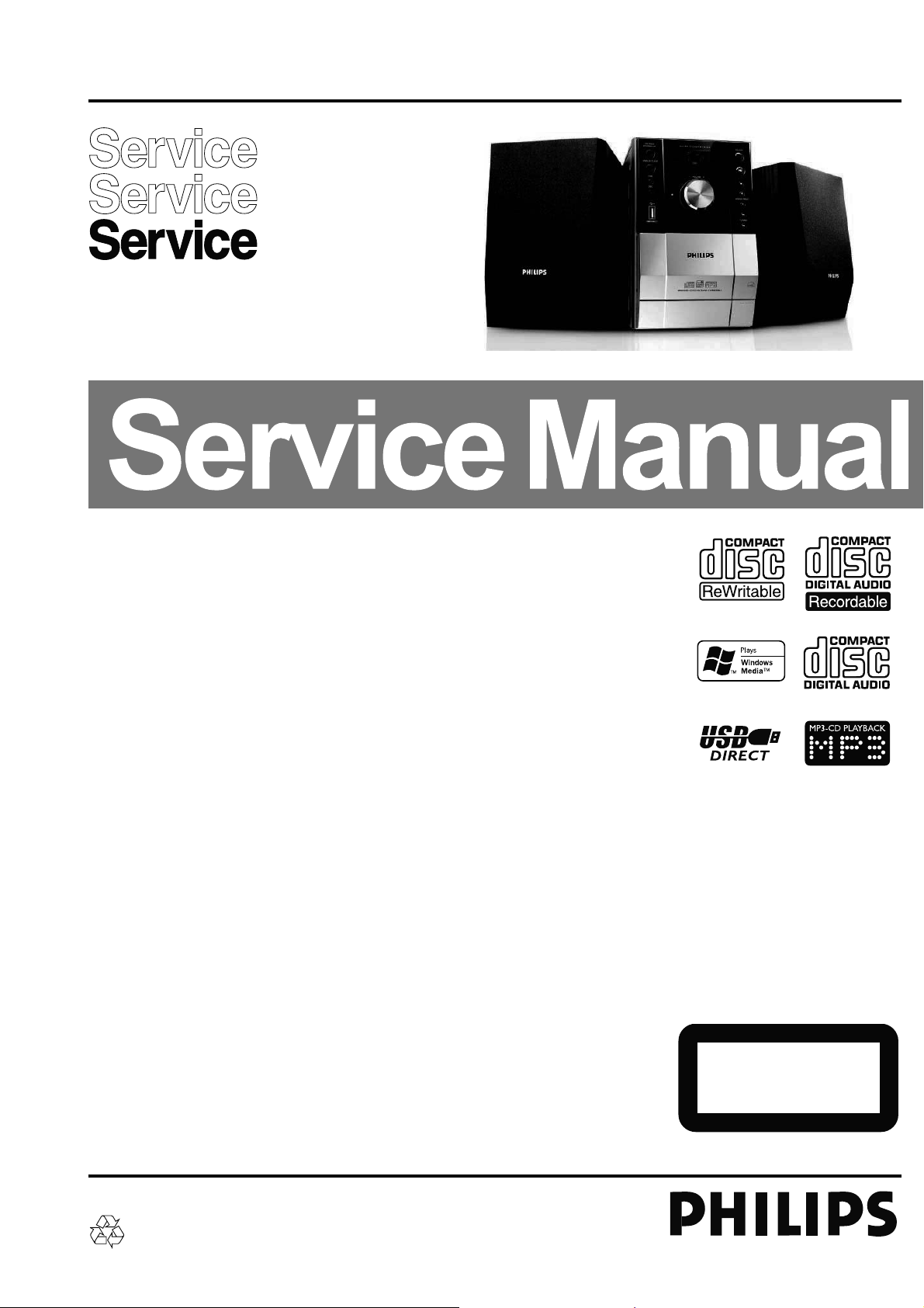
Micro System
MCM393/all version
TABLE OF CONTENTS
Page
PCBs Location ......................................................................1-2
Specifi cations .......................................................................1-3
Measurement Setup .............................................................1-4
Service Aids, Safety Instruction, etc ...........................1-5 to 1-7
Service Test Program ..............................................................2
Set Block Diagram ...................................................................3
Set Wiring Diagram .................................................................4
Main Board ..............................................................................5
Display & Headphone Board ...................................................6
MCU & USB Jack Board..........................................................7
Set Mechanical Exploded View & Parts List ............................8
Revision List ............................................................................9
©
Copyright 2007 Philips Consumer Electronics B.V. Eindhoven, The Netherlands
All rights reserved. No part of this publication may be reproduced, stored in a retrieval system or
transmitted, in any form or by any means, electronic, mechanical, photocopying, or otherwise without
the prior permission of Philips.
Published by SL 0833 Service Audio Printed in The Netherlands Subject to modification
Version 1.2
CLASS 1
LASER PRODUCT
© 3141 785 31552
Page 2
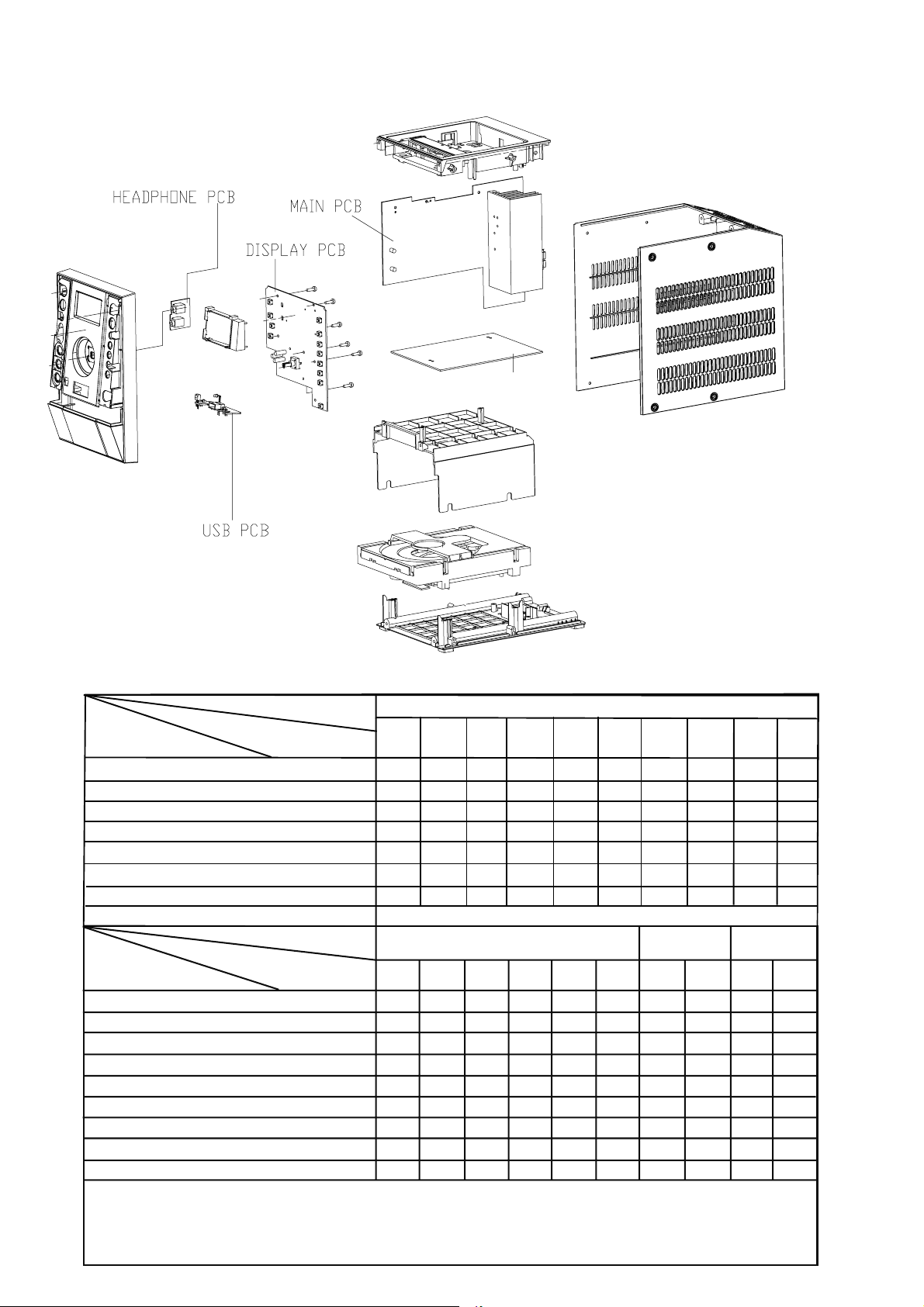
PCBS LOCATION
1-2
C MUSIC PCB
VERSION VARIATIONS
Board in used:
MAIN BOARD
DISPLAY BOARD
C MUSIC BOARD
USB BOARD
HEADPHONE BOARD
Features
in used:
niRDC/nixuA
Line Out
Video Out
Subwoofer Out
Digital Out
Karaoke Features
Voltage Selector
ECO Power Standby (LCD Display Off)
USB Direct
Type /Versions:
Service policy
/05 /12
M
C
M
C
C
Type /Versions: MCM393
Feature diffrence
/05
/12 /55
x
x
MCM393
/55
C
C
C
C
C
x
x
89/16/85/
* TIPS : C -- Component Lever Repair.
M -- Module Lever Repair
-- Used
x
Page 3

SPECIFICATIONS
1-3
AMPLIFIER
Output power ....................................... 2 x 15 W RMS
............................................................ 30 W + 30 W MPO
Signal-to-noise ratio .......................... t 62 dBA (IEC)
Frequency response ......... 40 – 15000 Hz, ± 3 dB
Impedance loudspeakers ......................................... 4 :
Impedance headphones .................... 32 : -1000 :
CD/MP3-CD PLAYER
Number of programmable tracks ......................... 20
Frequency range .................................. 20 – 20000 Hz
Signal-to-noise ratio ............................................ 75 dBA
Channel separation .......................... t 60 dB (1 kHz)
Total harmonic distortion ........................... < 0.003%
MPEG 1 Layer 3 (MP3-CD) .......... MPEG AUDIO
MP3-CD bit rate ....................................... 32-256 kbps
(128 kbps advised)
Sampling frequencies ....................... 32, 44.1, 48 kHz
USB PLAYER
USB ................................................................... 12Mb/s, V1.1
......................................... support MP3 and WMA files
Number of albums/folders ................. maximum 99
Number of tracks/titles ...................... maximum 500
SPEAKERS
2-way Bass reflex system
Dimensions (w x h x d) . 140 x 228 x 212 (mm)
GENERAL INFORMATION
AC Power..................................... 220 – 230 V / 50 Hz
Dimensions (w x h x d) .. 152 x 228 x 273 (mm)
Weight (with/without speakers)
............................................................... approx. 4.8 / 2.3 kg
Eco Power Standby ............................................... < 1 W
Power consumption Standby .......................... < 3 W
Specifications and external appearance are
subject to change without notice.
TUNER
FM wave range ................................... 87.5 – 108 MHz
MW wave range ................................ 531 – 1602 kHz
Sensitivity at 75 :
– mono, 26 dB signal-to-noise ratio ............ 2.8 µV
– stereo, 46 dB signal-to-noise ratio ........ 61.4 µV
Selectivity ................................................................. t 28 dB
Total harmonic distortion ..................................... d 5%
Frequency response ..... 63 – 12500 Hz (± 3 dB)
Signal-to-noise-ratio ...................................... t 50 dBA
Page 4
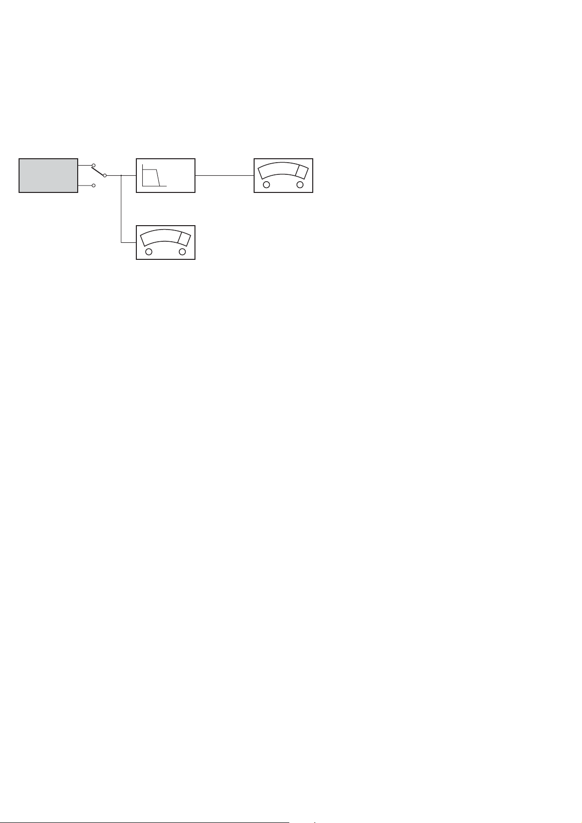
MEASUREMENT SETUP
CD
Use Audio Signal Disc SBC429 4822 397 30184 (replaces test disc 3)
L.P.F. = 13
th
order filter 4822 395 30204
1-4
DUT
Low pass filter 22kHz
L
R
S/N and distortion meter
e.g. Sound Technology ST1700B
LEVEL METER
e.g. Sennheiser UPM550
with FF-filter
Page 5
SERVICE AIDS
1-5
Service Tools:
Universal Torx driver holder .................................. 4822 395 91019
Torx bit T10 150mm ............................................. 4822 395 50456
Torx driver set T6 - T20 ......................................... 4822 395 50145
Torx driver T10 extended ...................................... 4822 395 50423
Cassette:
SBC419 Test cassette CrO2 ................................. 4822 397 30069
SBC420 Test cassette Fe ..................................... 4822 397 30071
MTT150 Dolby level 200nWb/M ............................ 4822 397 30271
Compact Disc:
SBC426/426A Test disc 5 + 5A ............................ 4822 397 30096
SBC442 Audio Burn-in Test disc 1kHz ................. 4822 397 30155
SBC429 Audio Signals disc .................................. 4822 397 30184
Dolby Pro-logic Test Disc ...................................... 4822 395 10216
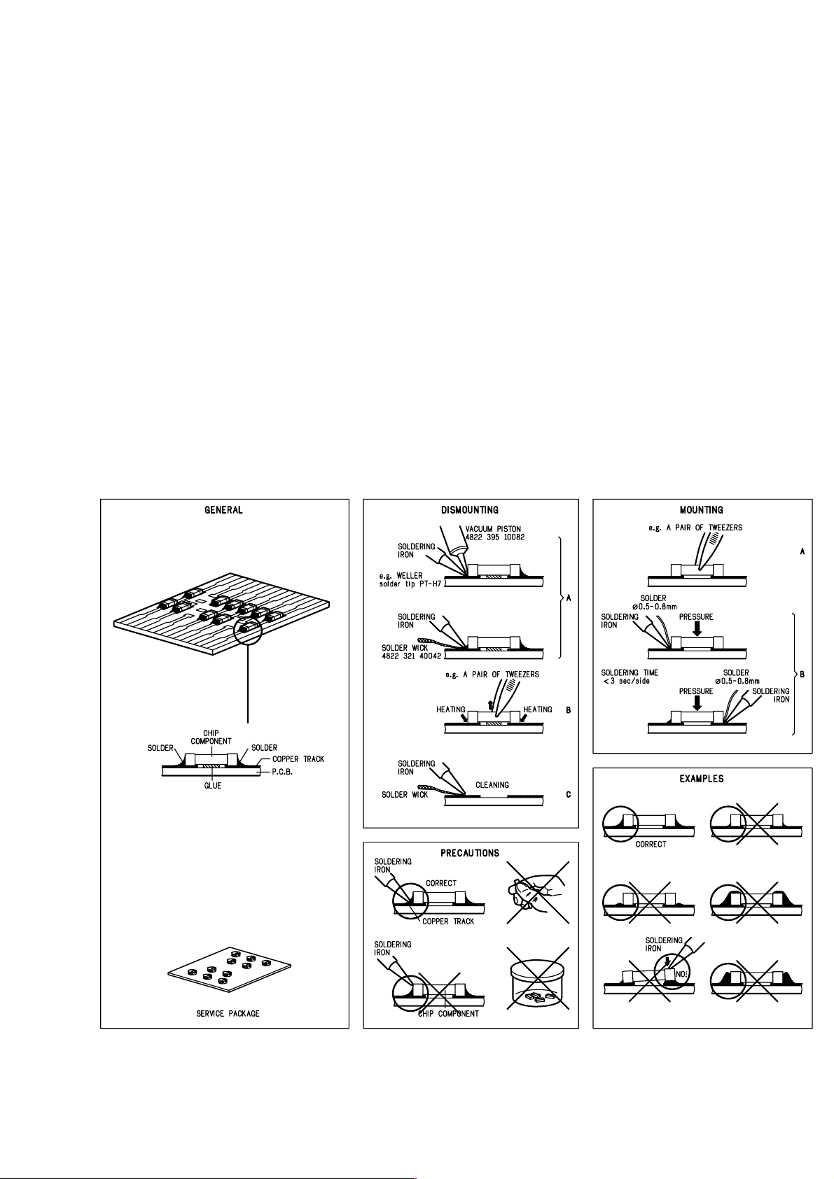
HANDLING CHIP COMPONENTS
ESD Equipment:
Anti-static table mat - large 1200x650x1.25mm ... 4822 466 10953
Anti-static table mat - small 600x650x1.25mm ..... 4822 466 10958
Anti-static wristband .............................................. 4822 395 10223
Connector box (1MΩ) ............................................ 4822 320 11307
Extension cable
(to connect wristband to conn. box) .................. 4822 320 11305
Connecting cable
(to connect table mat to conn. box) .................. 4822 320 11306
Earth cable (to connect product to mat or box) .... 4822 320 11308
Complete kit ESD3
(combining all above products) ......................... 4822 320 10671
Wristband tester .................................................... 4822 344 13999
Page 6
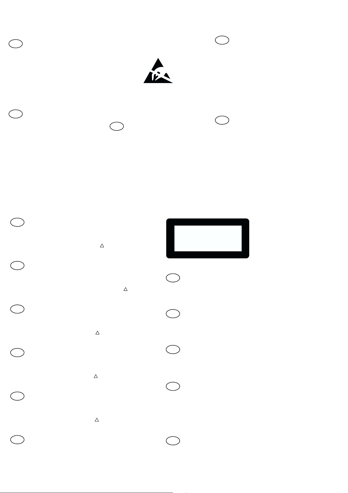
1-6
GB
All ICs and many other semi-conductors are
susceptible to electrostatic discharges (ESD).
Careless handling during repair can reduce life
drastically.
When repairing, make sure that you are
connected with the same potential as the mass
of the set via a wrist wrap with resistance.
Keep components and tools also at this
potential.
Tous les IC et beaucoup d’autres
semi-conducteurs sont sensibles aux
décharges statiques (ESD).
Leur longévité pourrait être considérablement
écourtée par le fait qu’aucune précaution n’est
prise à leur manipulation.
Lors de réparations, s’assurer de bien être relié
au même potentiel que la masse de l’appareil et
enfiler le bracelet serti d’une résistance de
sécurité.
Veiller à ce que les composants ainsi que les
outils que l’on utilise soient également à ce
potentiel.
F
WARNING
ATTENTION
ESD
D
WARNUNG
Alle ICs und viele andere Halbleiter sind
empfindlich gegenüber elektrostatischen
Entladungen (ESD).
Unsorgfältige Behandlung im Reparaturfall kan
die Lebensdauer drastisch reduzieren.
Veranlassen Sie, dass Sie im Reparaturfall über
ein Pulsarmband mit Widerstand verbunden
sind mit dem gleichen Potential wie die Masse
des Gerätes.
Bauteile und Hilfsmittel auch auf dieses gleiche
Potential halten.
NL
Alle IC’s en vele andere halfgeleiders zijn
gevoelig voor electrostatische ontladingen
(ESD).
Onzorgvuldig behandelen tijdens reparatie kan
de levensduur drastisch doen verminderen.
Zorg ervoor dat u tijdens reparatie via een
polsband met weerstand verbonden bent met
hetzelfde potentiaal als de massa van het
apparaat.
Houd componenten en hulpmiddelen ook op
ditzelfde potentiaal.
Tutti IC e parecchi semi-conduttori sono
sensibili alle scariche statiche (ESD).
La loro longevità potrebbe essere fortemente
ridatta in caso di non osservazione della più
grande cauzione alla loro manipolazione.
Durante le riparazioni occorre quindi essere
collegato allo stesso potenziale che quello della
massa dell’apparecchio tramite un braccialetto
a resistenza.
Assicurarsi che i componenti e anche gli utensili
con quali si lavora siano anche a questo
potenziale.
WAARSCHUWING
I
AVVERTIMENTO
GB
Safety regulations require that the set be restored to its original
condition and that parts which are identical with those specified,
be used
Safety components are marked by the symbol
!
.
NL
Veiligheidsbepalingen vereisen, dat het apparaat bij reparatie in
zijn oorspronkelijke toestand wordt teruggebracht en dat onderdelen,
identiek aan de gespecificeerde, worden toegepast.
De Veiligheidsonderdelen zijn aangeduid met het symbool
!
F
Les normes de sécurité exigent que l’appareil soit remis à l’état
d’origine et que soient utiliséés les piéces de rechange identiques
à celles spécifiées.
Less composants de sécurité sont marqués
!
D
Bei jeder Reparatur sind die geltenden Sicherheitsvorschriften zu
beachten. Der Original zustand des Geräts darf nicht verändert werden;
für Reparaturen sind Original-Ersatzteile zu verwenden.
!
Sicherheitsbauteile sind durch das Symbol
markiert.
I
Le norme di sicurezza esigono che l’apparecchio venga rimesso
nelle condizioni originali e che siano utilizzati i pezzi di ricambio
identici a quelli specificati.
Componenty di sicurezza sono marcati con
!
CLASS 1
LASER PRODUCT
GB
Invisible laser radiation when open.
Avoid direct exposure to beam.
Osynlig laserstrålning när apparaten är öppnad och spärren
är urkopplad. Betrakta ej strålen.
SF
Avatussa laitteessa ja suojalukituksen ohitettaessa olet alttiina
näkymättömälle laserisäteilylle. Älä katso säteeseen!
DK
Usynlig laserstråling ved åbning når sikkerhedsafbrydere er
ude af funktion. Undgå udsaettelse for stråling.
S
Warning !
Varning !
Varoitus !
Advarse !
GB
After servicing and before returning set to customer perform a leakage
current measurement test from all exposed metal parts to earth ground to
assure no shock hazard exist. The leakage current must not exceed
0.5mA.
F
"Pour votre sécurité, ces documents doivent être utilisés par
des spécialistes agréés, seuls habilités à réparer votre
appareil en panne".
Page 7
1-7
s
INFORMATION ABOUT LEAD-FREE SOLDERING
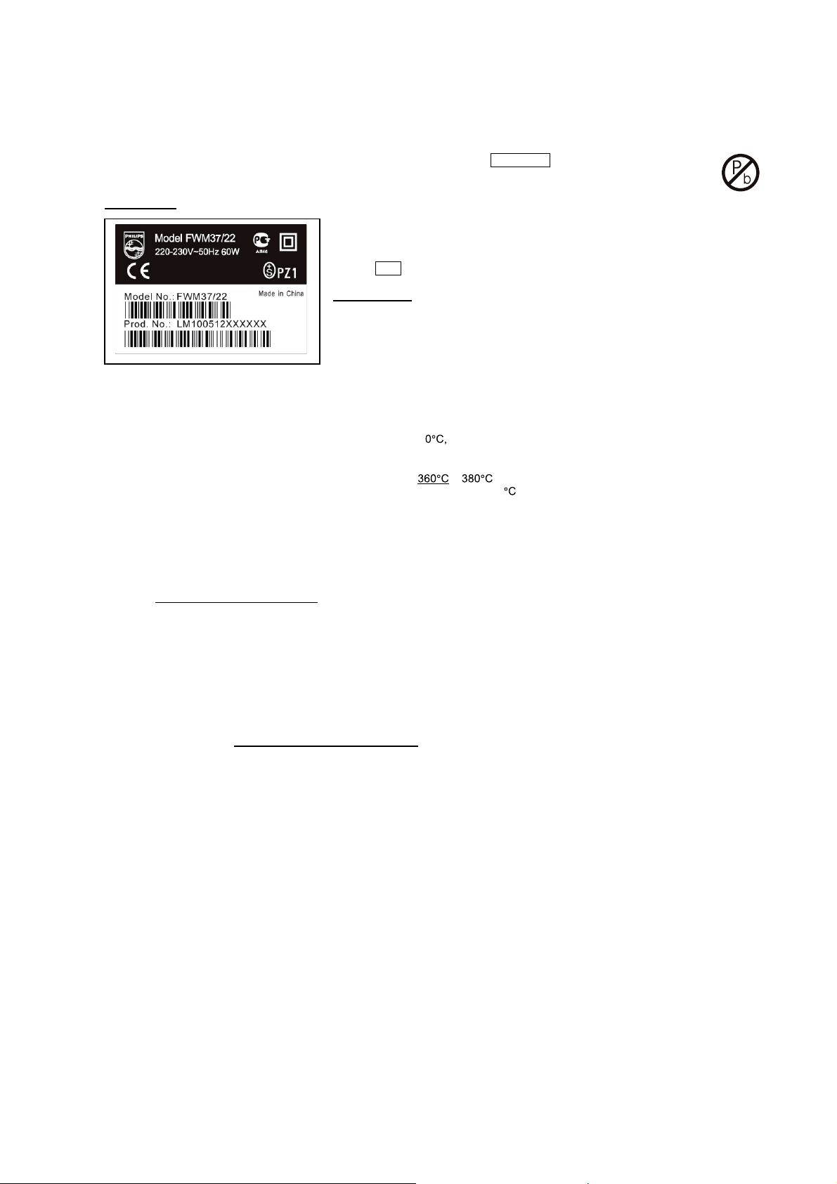
Philips CE is producing lead-free sets from 1.1.2005 onwards.
IDENTIFICATION:
Regardless of special logo (not always indicated) one must treat all sets from 1 Jan 2005 onwards, according next rules:
Example S/N:
Bottom line of typeplate gives a 14-digit S/N. Digit 5&6 is the year, digit 7&8 is the week number,
so in this case 2005 wk12
So from 0501 onwards = from 1 Jan 2005 onwards
Important note
you avoid mixing solder-alloys (leaded/ lead-free). So best to always use SAC305 and the
higher temperatures belong to this.
Due to lead-free technology some rules have to be respected by the workshop during a repair:
• Use only lead-free solder alloy Philips SAC305 with order code 0622 149 00106. If lead-free solder-paste is required, please contact
the manufacturer of your solder-equipment. In general use of solder-paste within workshops should be avoided because paste is not
easy to store and to handle.
• Use only adequate solder tools applicable for lead-free solder alloy. The solder tool must be able
o Toreach at least a solder-temperature of 40
o Tostabilize the adjusted temperature at the solder-tip
o Toexchange solder-tips for different applications.
• Adjust your solder tool so that a temperature around
solder-joint should not exceed ~ 4 sec. Avoid temperatures above 400 otherwise wear-out of tips will rise drastically and flux-fluid
will be destroyed. To avoid wear-out of tips switch off un-used equipment, or reduce heat.
• Mix of lead-free solder alloy / parts with leaded solder alloy / parts is possible but PHILIPS recommends strongly to avoid mixed
solder alloy types (leaded and lead-free).
If one cannot avoid or does not know whether product is lead-free, clean carefully the solder-joint from old solder alloy and re-solder
with new solder alloy (SAC305).
• Use only original spare-parts listed in the Service-Manuals. Not listed standard-material (commodities) has to be purchased at
external companies.
• Special information for BGA-ICs:
- always use the 12nc-recognizable soldering temperature profile of the specific BGA (for de-soldering always use the lead-free
temperature profile, in case of doubt)
- lead free BGA-ICs will be delivered in so-called 'dry-packaging' (sealed pack including a silica gel pack) to protect the IC against
moisture. After opening, dependent of MSL-level seen on indicator-label in the bag, the BGA-IC possibly still has to be baked dry.
(MSL=Moisture Sensitivity Level). This will be communicated via AYS-website.
Do not re-use BGAs at all.
• For sets produced before 1.1.2005 (except products of 2004), containing leaded solder-alloy and components, all needed spare-part
will be available till the end of the service-period. For repair of such sets nothing changes.
: In fact also products of year 2004 must be treated in this way as long as
− is reached and stabilized at the solder joint. Heating-time of the
• On our website www.atyourservice.ce.Philips.com
BGA-de-/soldering (+ baking instructions)
∗
Heating-profiles of BGAs and other ICs used in Philips-sets
∗
You will find this and more technical information within the "magazine", chapter "workshop news".
For additional questions please contact your local repair-helpdesk.
you find more information to:
SERVICE INSTRUCTION
Safety regulations require that after a repair, the set must be returned in its original condition. Pay in particular attention to
the following points:
· Route the wire trees correctly and fix them with the
mounted cable clamps.
· Check the insulation of the AC Power lead for external
damage.
· Check the strain relief of the AC Power cord for proper
function.
· Check the electrical DC resistance between the AC Power
Plug and the secondary side (only for sets which have a AC
Power isolated power supply):
1. Unplug the AC Power cord and connect a wire
between the two pins of the AC Power plug.
2. Set the AC Power switch to the "on" position (keep the
AC Power cord unplugged!).
3. Measure the resistance value between the pins of the
AC Power plug and the metal shielding of the tuner or
the aerial connection on the set. The reading should be
larger than 4.5 Mohm (For U.S. it should be between
4.2 Mohm and 12 Mohm).
4. Switch "off" the set, and remove the wire between the
two pins of the AC Power plug.
• Check the cabinet for defects, to avoid touching of any
inner parts by the customer.
Page 8
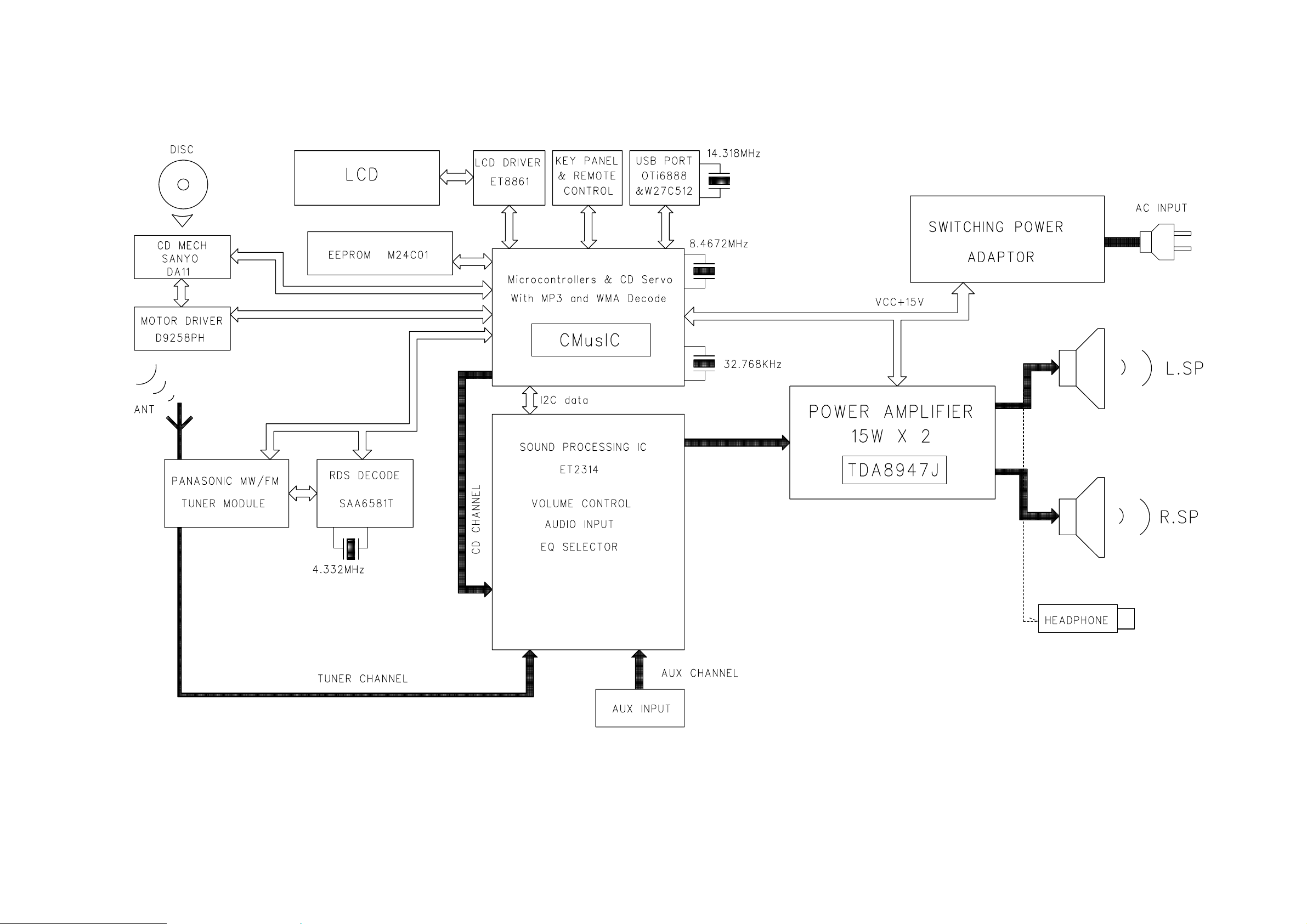
SET BLOCK DIAGRAM
3-1
3-1
Page 9
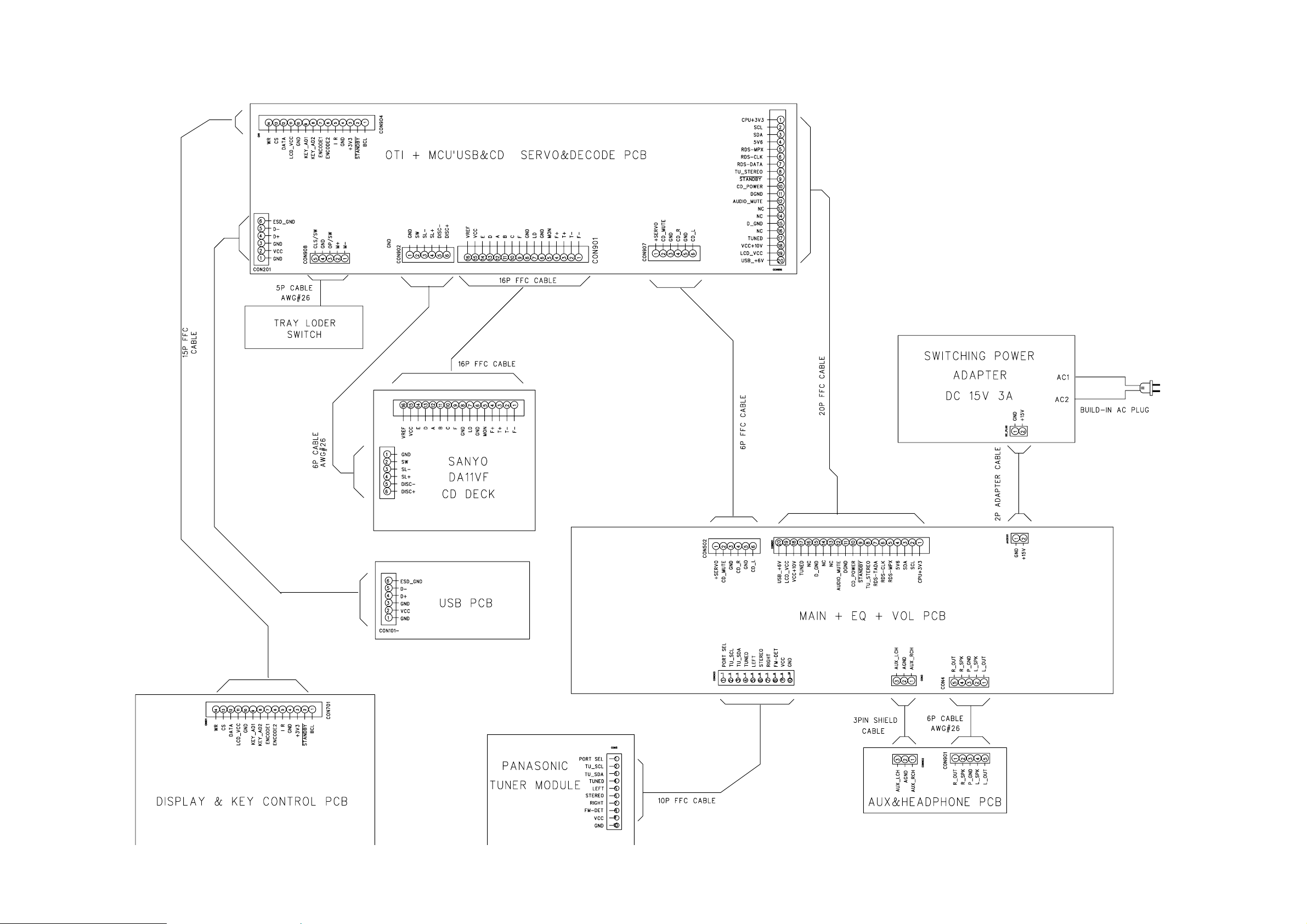
SET WIRING DIAGRAM
4-1
4-1
Page 10

5-1 5-1
MAIN BOARD
TABLE OF CONTENTS
Main PCB - Layout Top View ...........................................5-2
Main PCB - Layout Bottom View .....................................5-3
Main & Headphone PCB - Circuit Diagram ......................5-4
Headphone PCB - Layout Diagram ................................. 5-5
Page 11
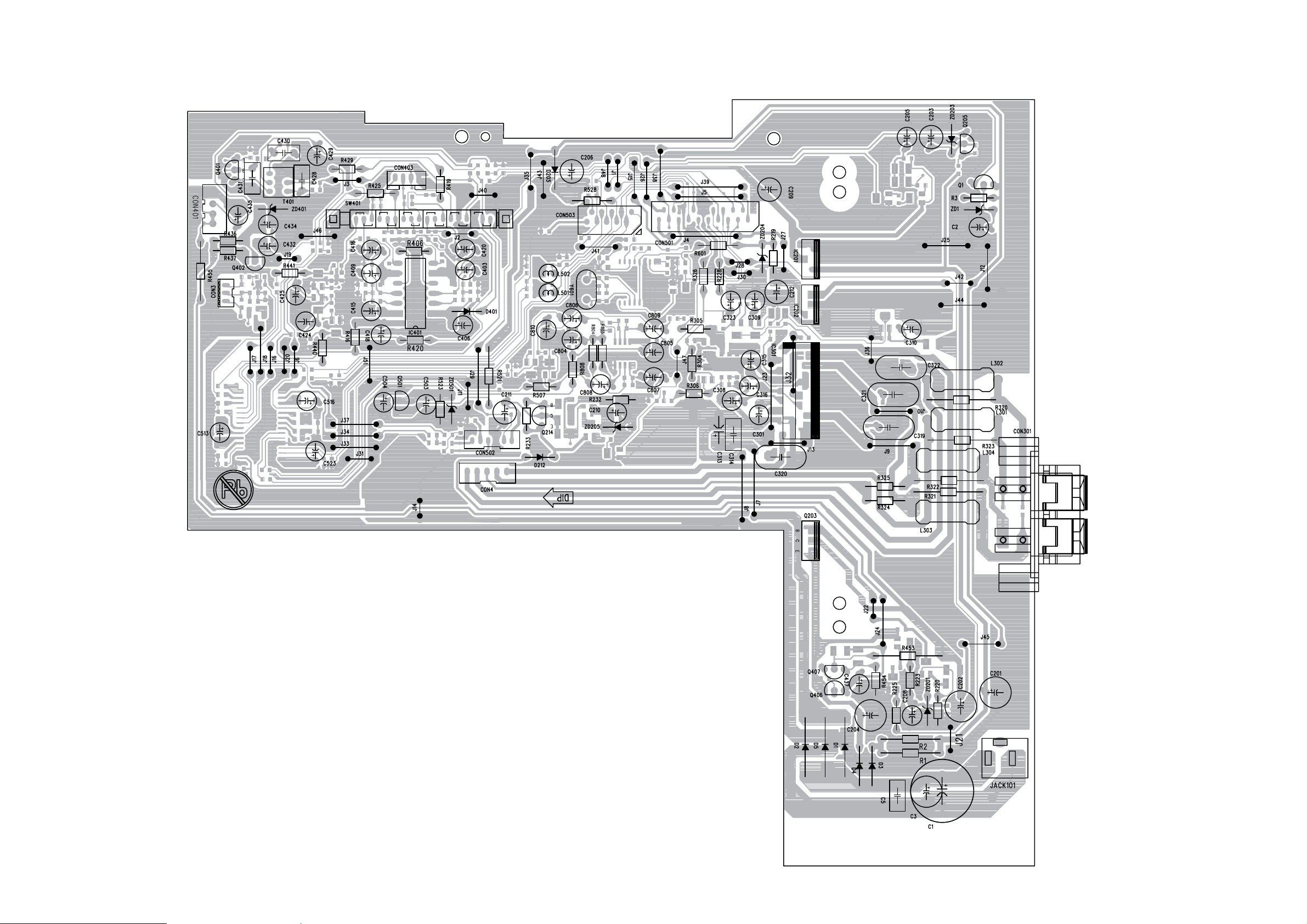
5-2 5-2
PCB LAYOUT - MAIN BOARD (TOP VIEW)
Page 12
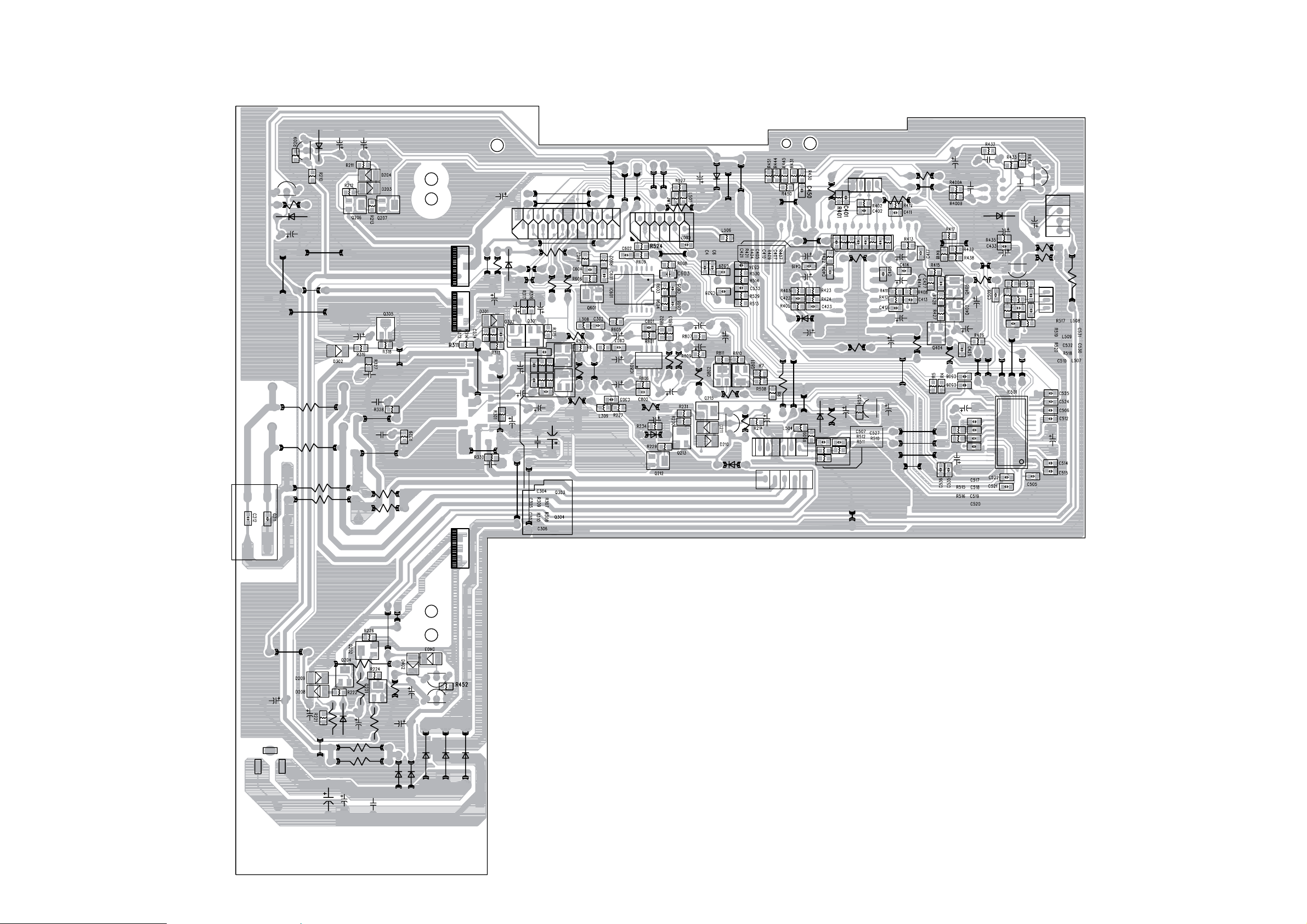
5-3
PCB LAYOUT - MAIN BOARD (BOTTOM VIEW)
5-3
Page 13
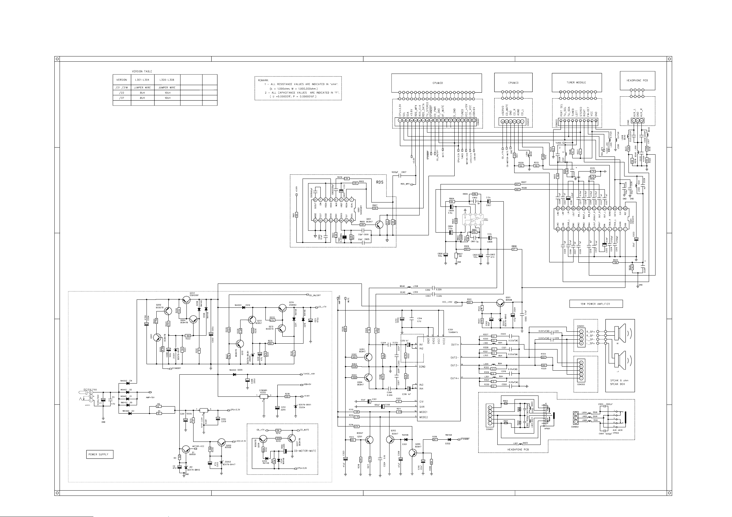
CIRCUIT DIAGRAM - MAIN BOARD
5-4
5-4
Page 14
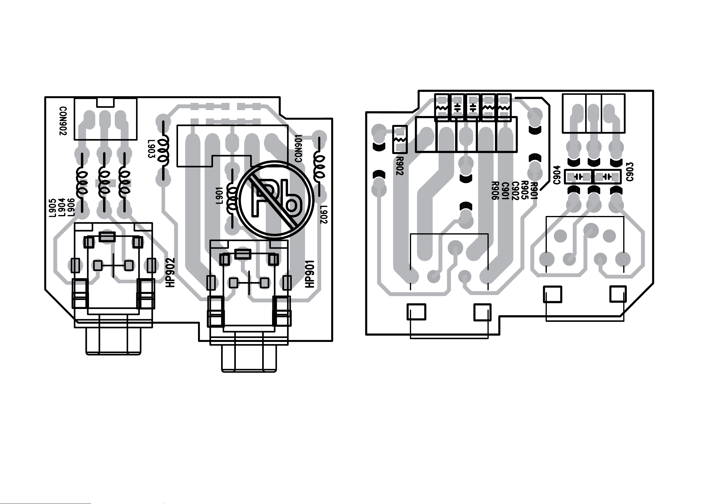
5-5
5-5
PCB LAYOUT - HEADPHONE BOARD (TOP VIEW) PCB LAYOUT - HEADPHONE BOARD (BOTTOM VIEW)
Page 15

6-1 6-1
DISPLAY BOARD
TABLE OF CONTENTS
Display PCB - Layout Top View .......................................6-2
Display PCB - Layout Bottom View .................................6-3
Display PCB - Circuit Diagram .........................................6-4
Page 16
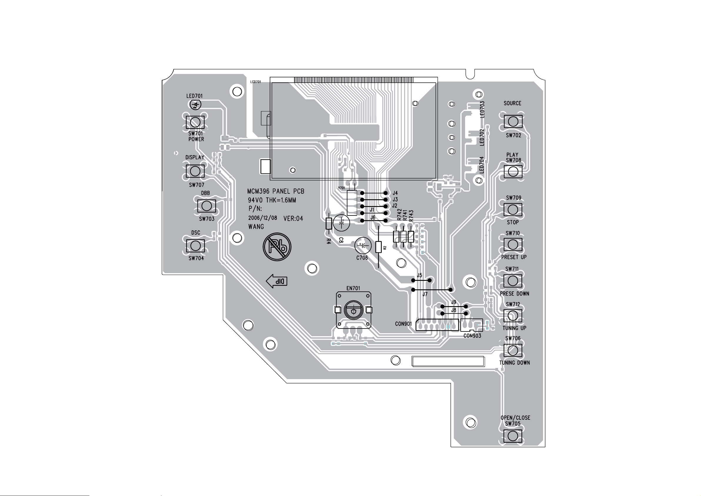
6-2 6-2
PCB LAYOUT - DISPLAY BOARD (TOP VIEW)
Page 17
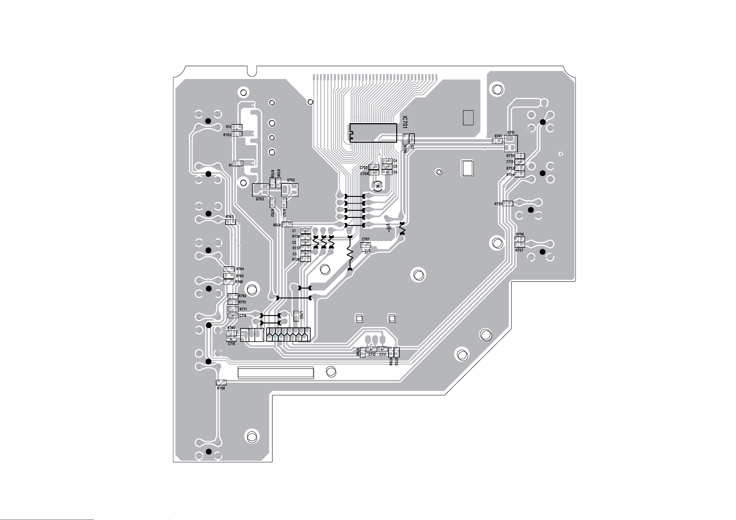
6-3
PCB LAYOUT - DISPLAY BOARD (BOTTOM VIEW)
6-3
Page 18
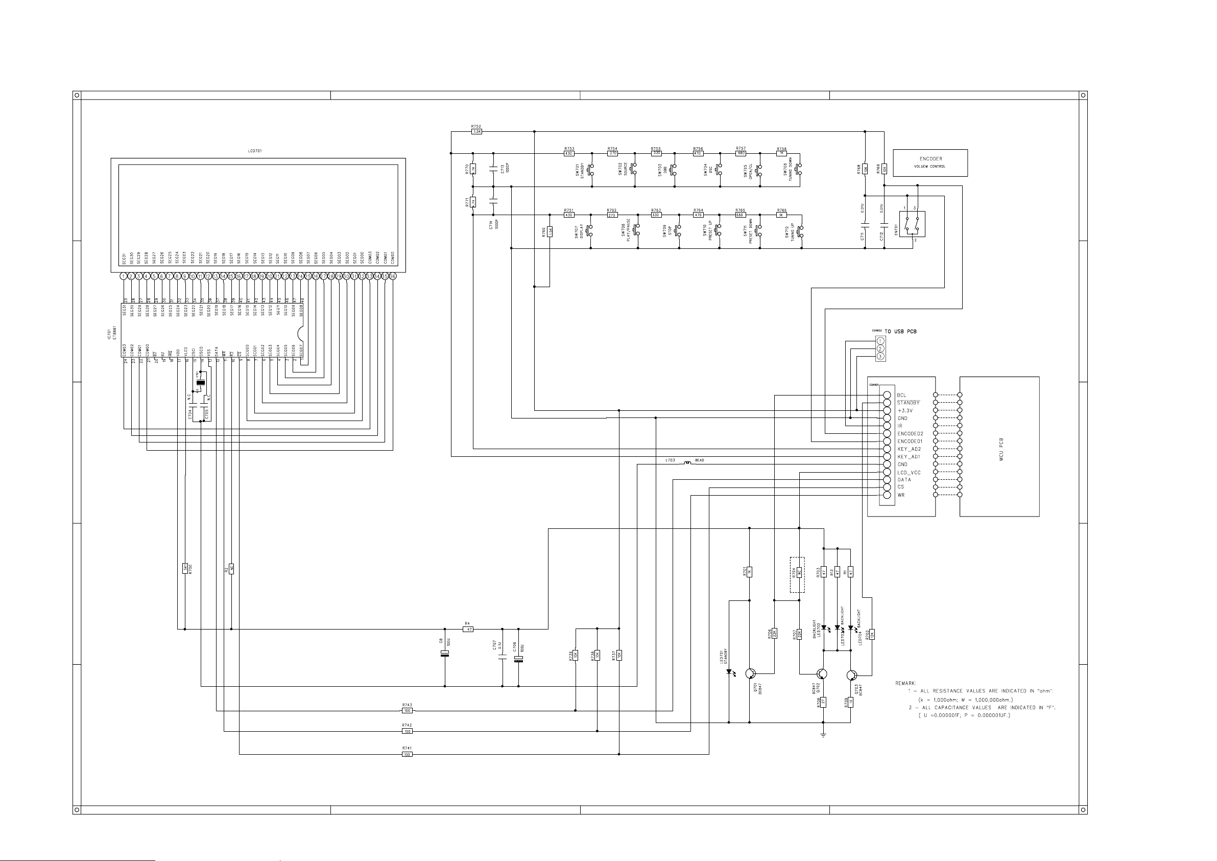
CIRCUIT DIAGRAM - DISPLAY BOARD
6-4
6-4
Page 19

7-1
MCU & USB JACK BOARD
7-1
TABLE OF CONTENTS
MCU PCB - Layout Top View ...........................................7-2
MCU PCB - Layout Bottom View ......................................7-3
MCU PCB - Circuit Diagram ............................................. 7-4
USB JACK PCB - Circuit Diagram....................................7-5
USB JACK PCB - Layout Diagram ................................... 7-6
Page 20
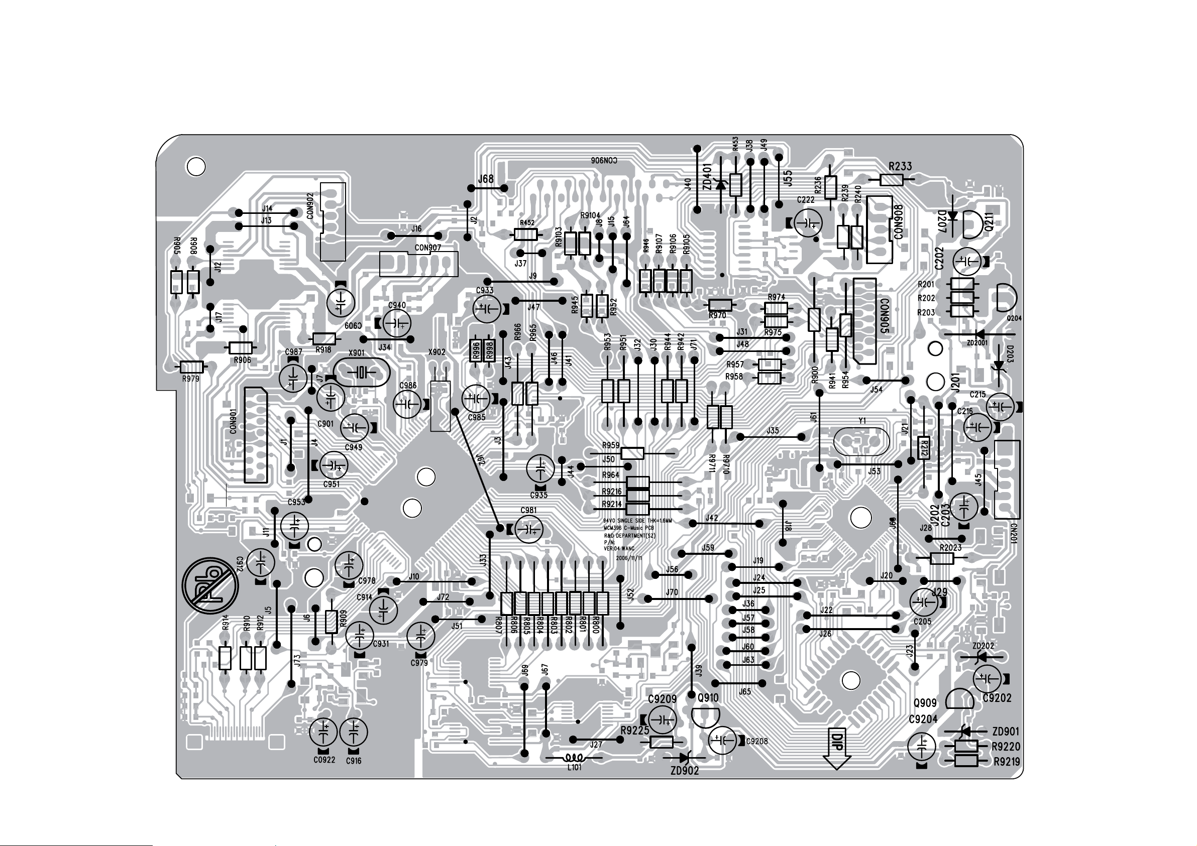
7-2
PCB LAYOUT - MCU BOARD (TOP VIEW)
7-2
Page 21
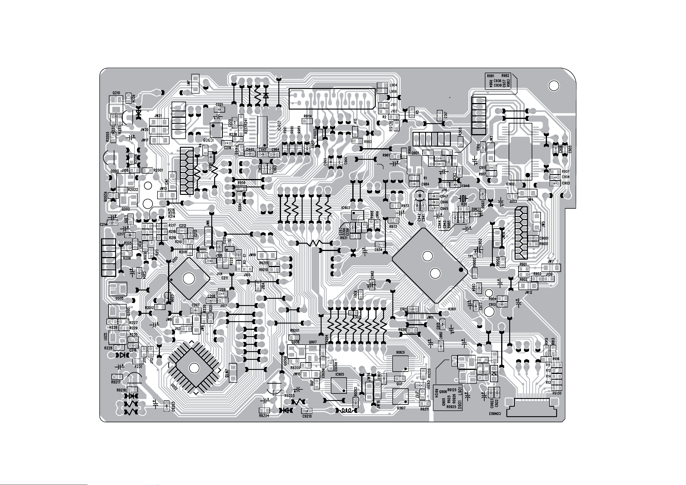
7-3
PCB LAYOUT - MCU BOARD (BOTTOM VIEW)
7-3
Page 22
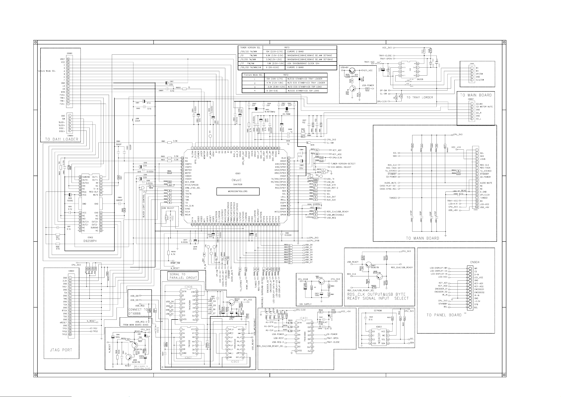
CIRCUIT DIAGRAM - MCU BOARD
7-4
7-4
Page 23
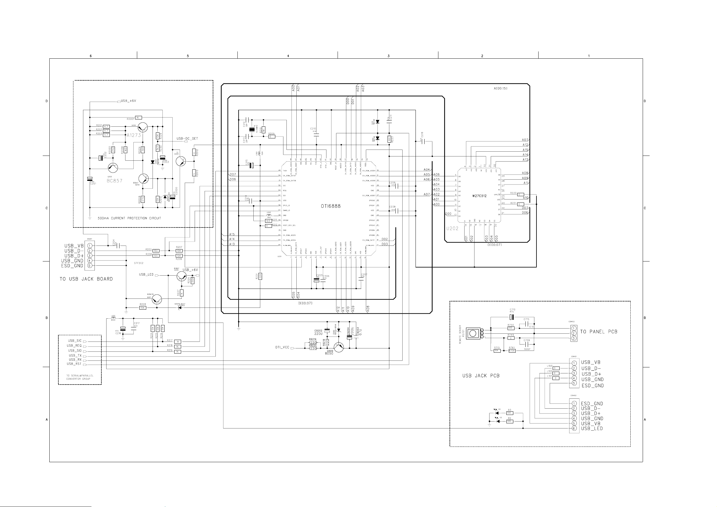
7-5
CIRCUIT DIAGRAM - USB JACK BOARD
7-5
Page 24
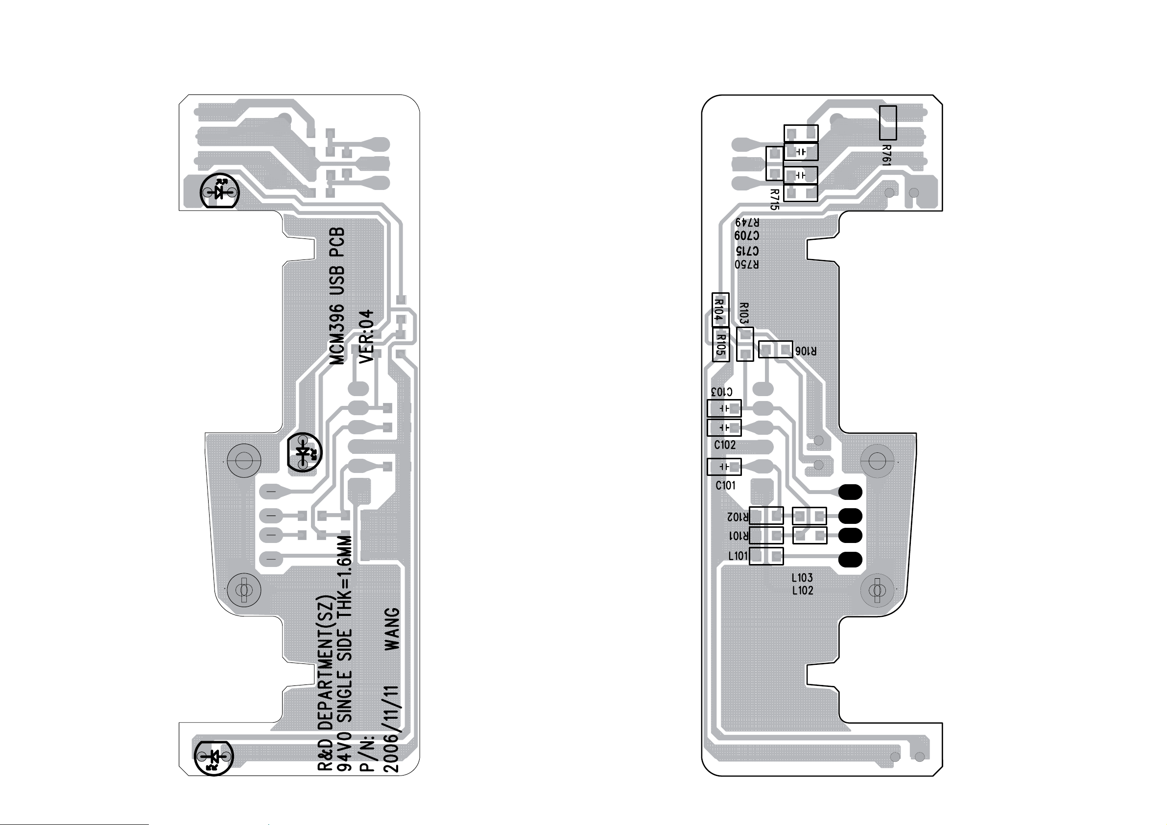
7-6
7-6
PCB LAYOUT - USB JACK BOARD (TOP VIEW)
PCB LAYOUT - USB JACK BOARD (BOTTOM VIEW)
Page 25
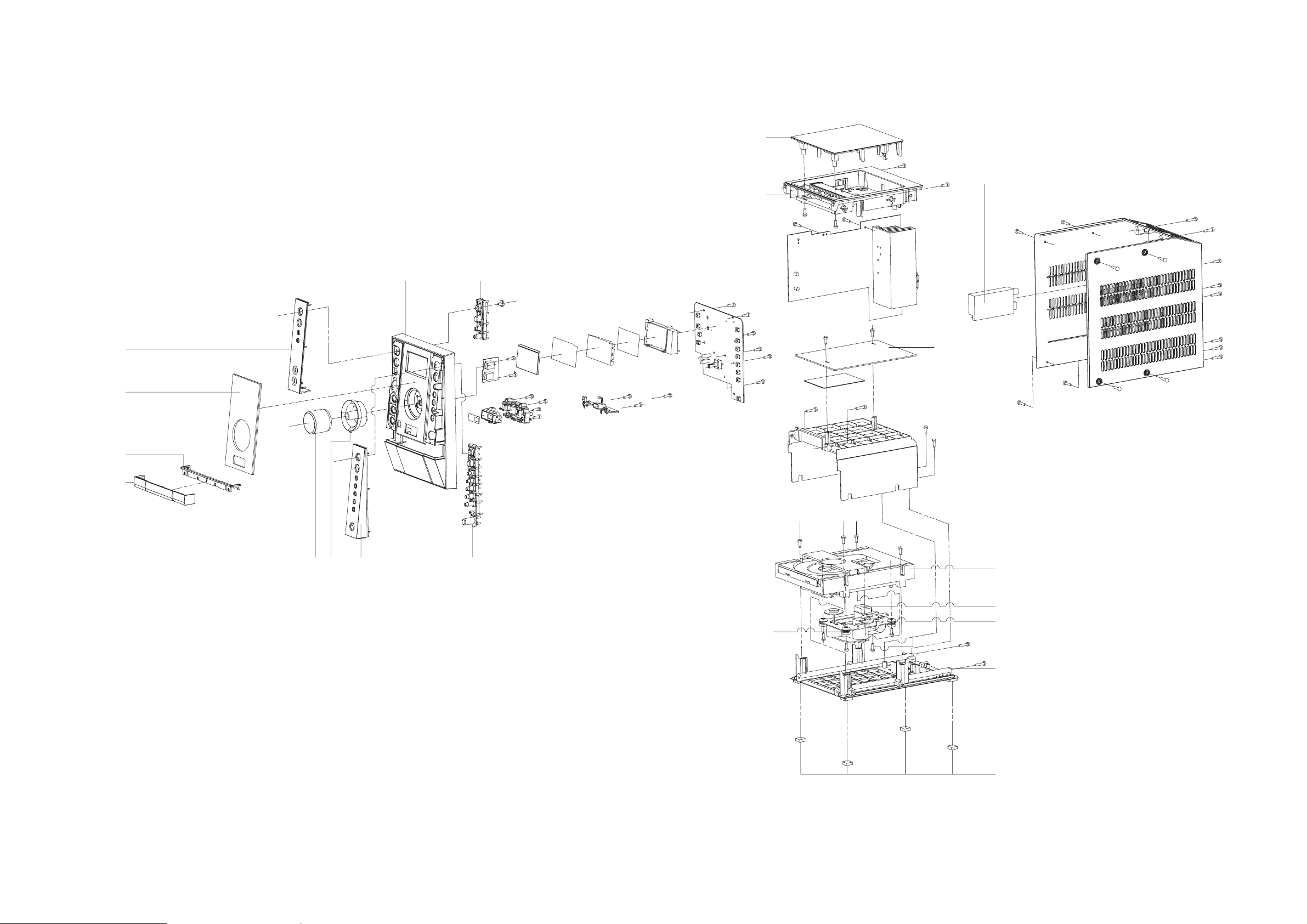
SET MECHANICAL EXPLODED VIEW
8-1
8-1
12
26
14
21
11
20
19
16
23
22
13
18
17
4A
25
24
9
9
15
10
Page 26

8-2
MECHANICAL & ACCESSORIES PARTS LIST
9 996510000868 CD DAMPER PINK 658F HARDNESS
10 996510001076 RUBBER FOOT 11.8X11.8X6MM
11 996510001077 DISPLAY LENS
12 996510001078 TOP COVER
13 996510001079 FRONT CABINET
14 996510001080 TOP CABINET
15 996510001081 BOTTOM CABINET
16 996510001082 VOLUME KNOB
17 996510001083 CONTROL KEY SET - LEFT
18 996510001084 CONTROL KEY SET - RIGHT
19 996510001085 CD LOADER COVER
20 996510001086 CHROME RING - CD LOADER COVER
21 996510001087 LEFT FRONT PANEL
22 996510001088 RIGHT FRONT PANEL
23 996510001089 VOLUME KNOB RING
24 994000005786 CD MECHANISM DA11VF(SANYO)
25 996510000871 CD TRAY LOADER
26 996510001090 TUNER MODULE ENG07821QF
27 996510001091 FFC CABLE 80MM 14P P1.0
28 996510001092 FFC R/A TYPE 16P L180MM
29 996510001093 FFC CABLE 20P P1.25MM L200MM
30 996510001094 FFC CABLE 200MM 20P P1.25
31 996510001095 FFC CABLE 10P L300MM P1.25
32
33 996510001097 WOODEN SPEAKER (L+R)ONE SET
34 996510001098 REMOTE CONTROL
35 994000003268 ANTENNA WIRE 1000MM
36 996510001099 AM LOOP FRAME ASSY
4A 996520000101 C MUSIC BOARD ASSY
02
Note: Only these parts mentioned in the list are
! 996510001096 POWER AC ADAPTER 15V 3A
996510019243
normal service parts.
MAIN BOARD ASSY
Page 27

D
D
8-3
ELECTRICAL PARTS LIST - MAIN BOAR
ELECTRICAL PARTS LIST - C MUSIC (MCU)
BOARD (only for reference)
CON301 996510000380 PUSH TERMINAL JACK PST-418 IC401 994000003199 IC HEF4094BT
D4 996510001053 RECTIFIER DIODE RL201 IC901 996510001066 C MUSIC PLUS IC SAA7838H/N3
IC201 996510001057 IC S1117-33PIC TO-220F-3SL IC901 996510001067 C MUSIC PLUS IC SAA7838/M3
IC202 996510001058 IC S7806PI TO-220F IC901 996510001068 C MUSIC PLUS IC SAA7838H/N3
IC301 994000003203 POWER AMPLIFIER IC TDA8947J IC902 994000005753 I.C. D9258PH
T6WDR-10C42M CI272300000499309CI4132TE CI650100015699105CI
IC601 994000003215 RDS IC SAA6581T IC905 994000005751 I.C. 74HC4520DB SSOP16
IC801 996510001055 IC BA4558 SOP8 IC906 994000005749 I.C. 74HC4094DB SSOP16
JACK101 996510001054 6.5MM DC JACK (DJ32-2) IC907 994000005748 I.C. 74HC02DB SSOP14
L301 996510000388 CHOKE COIL 8UH 3A1941N IC908 996510001069 IC D6208 SOP8
L302 996510000388 CHOKE COIL 8UH 3A1941N L205 996510001060 FER. BEAN SBK160808T-601Y-S
L303 996510000388 CHOKE COIL 8UH 3A1941N L901 996510001060 FER. BEAN SBK160808T-601Y-S
L304 996510000388 CHOKE COIL 8UH 3A1941N L904 996510001060 FER. BEAN SBK160808T-601Y-S
Q1 996500039268 TRANSISTOR KTC-8050C L906 996510001060 FER. BEAN SBK160808T-601Y-S
Q203 994000001436 TRANSISTOR 2SB1566-F Q204 994000005729 TRANSISTOR KTA1273 TO-92L
Q205 996500039268 TRANSISTOR KTC-8050C Q211 994000005729 TRANSISTOR KTA1273 TO-92L
Q214 994000005727 TRANSISTOR 2SB562C TO-92MOD Q901 996510000378 TRANSISTOR?BST50
Q501 996500039268 TRANSISTOR KTC-8050C Q909 996500039268 TRANSISTOR KTC-8050C
Y601 994000003209 CRYSTAL 4.332MHZ HC-49/S Q910 996500039268 TRANSISTOR KTC-8050C
U201 994000005747 IC OTI6888-G LQFP-64
U202 996510000738 IC EPROM ICE27C512-70?PCW
ELECTRICAL PARTS LIST - DISPLAY BOAR
D704 996510001062 3.1MM RED COLOR LED X902 994000003208 X'TAL 32.768KHZ 12.5PF -10P
EN701 996510001059 ENCODER EC121102X2B-HA1-082 Y1 994000005741 X'TAL 14.318 MHZ 20PF
IC701 996510001064 IC ET8861S (FOR LCD DRIVER)
L703 996510001060 FERR. BEAN SBK160808T-601Y-S ZD2001 994000005744 ZENER DIODE 5V1 1/2W
LCD701 996510001061 LCD DISPLAY GS-34301+HSC-A/P ZD202 994000005743 ZENER DIODE 2V7 1/2W
LED701 996510000394 LED INDICATOR RED4.3X2.98MM ZD901 996500039267 ZENER DIODE 3V9 1/2W
LED702 996510001062 3.1MM RED COLOR LED ZD902 996500039267 ZENER DIODE 3V9 1/2W
LED702 996510001063 D3MM LED RED 4.1X2.97MM
LED703 996510001062 3.1MM RED COLOR LED
LED703 996510001063 D3MM LED RED 4.1X2.97MM
LED704 996510001063 D3MM LED RED 4.1X2.97MM
SW701 996500039269 TACT SWITCH
SW702 996500039269 TACT SWITCH
SW703 996500039269 TACT SWITCH
SW704 996500039269 TACT SWITCH
SW705 996500039269 TACT SWITCH
SW706 996500039269 TACT SWITCH
SW707 996500039269 TACT SWITCH
SW708 996500039269 TACT SWITCH
SW709 996500039269 TACT SWITCH
U202 996510001065 IC EPROM ICE27C512-70
X901 994000005742 X'TAL 8.4672 MHZ 20PF
ZD401 996500039267 ZENER DIODE 3V9 1/2W
SW710 996500039269 TACT SWITCH
SW711 996500039269 TACT SWITCH
SW712 996500039269 TACT SWITCH
Note: Only these parts mentioned in the list are
normal service parts.
Page 28

D
D
8-4
ELECTRICAL PARTS LIST - USB JACK BOAR
CON102 996510001071 USB JACK 4P ANGLE TYPE
D101 996510001072 LED INDICATOR D3 CLEAR BLUE
D102 996510001072 LED INDICATOR D3 CLEAR BLUE
D103 996510001072 LED INDICATOR D3 CLEAR BLUE
L101 996510001060 FERRITE BEAN SBK160808T-601Y-S
RS701 996510001070 INFRARED RECEIVER SM3385B
ELECTRICAL PARTS LIST - HEADPHONE BOAR
HP901 994000001456 STEREO HEADPHONE JACK
HP902 996510001073 EARPHONE CKX3.5-19S (3PIN)
Note: Only these parts mentioned in the list are
normal service parts.
Page 29

REVISION LIST
1.0 Manual 3141 785 31550
Initial Service Manual released.
1.1 Manual 3141 785 31551
In this version, on Page 1-2, Version Variations added
and Page 8-2 Mechanical & Accessories Parts List is updated.
add:
4A 996520000101 C MUSIC BOARD ASSY
1.2 Manual 3141 785 31552
In this version,
Page 8-2 Mechanical & Accessories Parts List is updated.
add:
02 996510019243 MAIN BOARD ASSY
9-1
 Loading...