

Philips MCM1050B/05, MCM1050B/10, MCM1050B/12, MCM1050B/37, MCM1050B/55 Service Manual
...
Published by Sophie-KM 122901 AVM Printed in the Netherlands
MCM1050B/12/58
Subject to modi cation EN
Micro Audio System
egaPstnetnoC
Contents
Page
©
Copyright 2011 Philips Consumer Electronics B.V. Eindhoven, The Netherlands.
All rights reserved. No part of this publication may be reproduced, stored in a
retrieval system or transmitted, in any form or by any means, electronic,
mechanical, photocopying, or otherwise without the prior permission of Philips.
Version 1.0
1 Technical Specification and Connection Facilities
2 Laser Beam Safety Precautions......................................... 2-1
3 Important Safety Precautions .................................. 3-1 to 3-2
4 Safety Check After Servicing ............................................. 4-1
6 Standard Notes For Servicing,Lead Free Requirements
& Handling Flat Pack IC .......................................... 6-1 to 6-4
5 Safety Information General Notes & Lead Free
7 Direction of Use ....................................................... 7-1 to 7-2
8 Cabinet Disassembly Instructions ........................... 8-1 to 8-2
12 DC/MP3 Link/WPS Board
9 Troubleshooting ................................................................. 9-1
10 Block Diagram .................................................................10-1
11 Wiring Diagram ...............................................................11-1
13 Key Board
14 AMP Board
Layout Diagram.................................................12-5
15 MCU Board
16 Exploded View.....................................................................13-1
17 Revision List ........................................................................14-1
Circuit Diagram .................................................12-6
Layout Diagram ................................................12-7
.................................................1-1 to 1-7
Circuit Diagram ....................................................12-1
Layout Diagram ...................................................12-1
Circuit Diagram ................................................12-2
Circuit Diagram .................................................12-4
Layout Diagram ...............................................12-3
Requirements .................................................................... 5-1
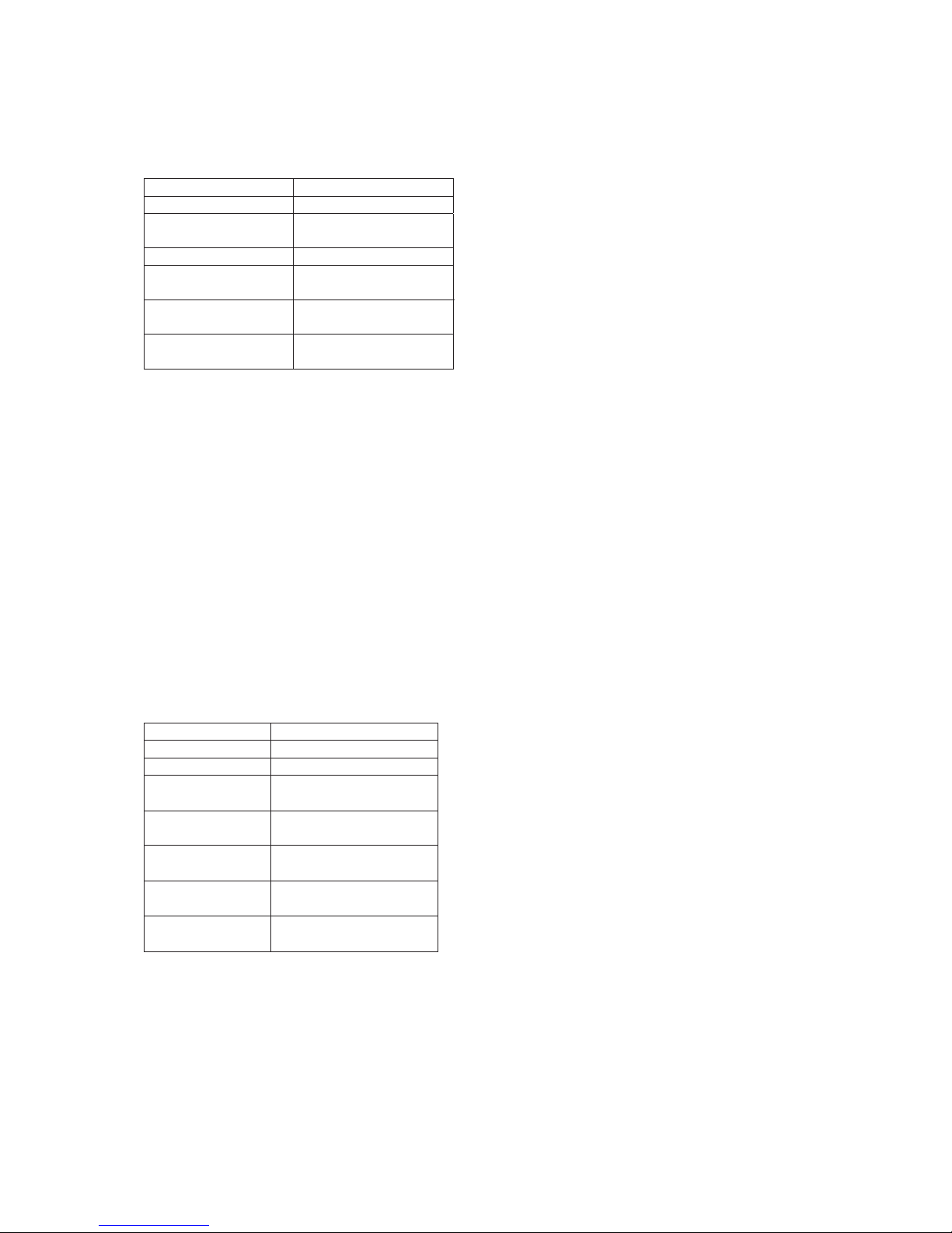
Features
RDS
Voltage Selector
ECO Standby
DTS
Feature
Different
/12
/58

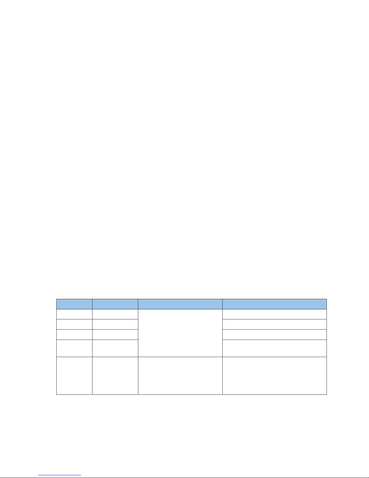
1.Location of PC Boards
Version Variations
Type /Versions:
Features
Board in used:
MCM1050B
Service policy
* TIPS : C -- Component Lever Repair.
M -- Module Lever Repair
-- Used
/55
/55
/58
/58
/61
/61
/79
/79
/93
/93
/94
/94
/96
/96
/98
/98
/37
/37
/12/10
CC
CC
MM
MM
/12/10
/05
/05
Feature diffrence
RDS
AMP Board
Decoder Board
Power Board
DTS
VOLTAGE SELECTOR
ECO STANDBY - DARK
Type /Versions
MCM1050B
Technical Specification and Connection Facilities
1-1
Display Board
Decoder Board
Display Board
Power Board
AMP Board

2. General Information and Requirement
2.1 Product Family Features
2.1.1 Identity and Key Features
MCM1050 series are Micro Audio System with CD/MP3 player with USB and Tuner
FM(20presets)
Elements to include as generic requirements:
1. Detachable mains cord
2. Safety certification (cUL/FCC and CB/EMC/CE)
Following is a list of key features:
1. CD /MP3 disc player (Ali-M5673)
2. USB true source
a) MSC/MTP device
b) USB 2.0HS
3. MP3 Link (via headphones jack from PC or MP3 player)
4. Headphone Out (in front of the set)
5. Tuner FM(Silicon Lab SI4705/w RDS)
6. Digital Amplifier (ST class D,TDA7491HV)
7. Rated output power @10%THD table 2
Set Type Number Stroke Versions Power(ROP) Power(Volume max) Remark
MCM1050
All version 2x5W
2x12W
2.1.2 Styling, Forms and Functions
MCM1050 appearances are defined in their respective MUS. MUS is the leading document
where product appearance is applicable..
Features Products MCM1050
Stroke versions
llA
Design
Refer to MUS[3] for
details
Front
Optical Drive Loading Tray
elddiM noitacoL yarT
Tray Orientation HORIZONTAL
PU DCL
Dimension
mm3 teef fo thgieH
Apparatus tray closed
W x D x H (mm)
140x143x210mm
Weight
gk2.1 tes niaM
gk50.1 rekaeps
Cosmetics
Black
Black
roloC
snottuB
Technical Specification and Connection Facilities
1-2
2.1.3 External I/O Connections
Model MCM1050
Stroke Version All
iPod dock with
Authentication chip
NA
USB √
MP3 Link
(3.5mm audio jack)
√
Tuner Socket
(for FM)
√
Headphone Out
(3.5mm audio jack)
√
2.1.4 Controls, Local Display and LED Indications(tbc)
Control keys on the set are:
1. Standby-On
2. Eject
3. Play/Pause
4. Next
5. Pre
6. FF
7. FB
8. Source (Disc, USB, Dock, FM, Aux, MP3)
9. Stop
10. Volume Knob
There is local display LCD(reuse). Standby LED colour: Red in Standby mode.
2.1.5 ACCESSORIES (tbc)
Model MCM1055
Stroke Version All Version
noig
Power Cord
eR
Audio cable
(3.5mm audio)
0.5M
Remote Control
31keys
Quickly guide
1
IFU
1
Technical Specification and Connection Facilities
1.5M
1-3

2.2 Mechanical General Information
The product appearances and functions are defined in their respective MUS. Product management
approves the MUS and it is a leading document where product appearance is applicable.
Please refer to Sh560 for mechanical information.
2.3
Safety Standards
Where applicable:
For /12 (EU), /05 (UK), /51 (Russia) EN/IEC 60065 7
th
Edition
For /37 (US, Canada) UL 60065
For /55 (LATAM), /78 (Brazil) IEC 60065 7
th
Edition
For /98 (AP), /69 (Singapore), /75 (Australia) IEC 60065 7
th
Edition
For /93 (China) GB 8898 (IEC 60065 7
th
Edition)
For /61 (Korea) K 60065 6
th
Edition
For /96 (Taiwan) CNS 14408 (IEC 60065 7
th
Edition)
2.4
EMC Requirements
Where applicable:
For /12 (EU), /05 (UK), /51 (R
ussia) EN55013: 2001, EN55020: 2002
For /37 (US, Canada) FCC15
For /55 (LATAM), /78 (Brazil) CISPR13
For /98 (AP), /69 (Singapore), /75 (Australia) CISPR13
For /61 (Korea) CISPR13/20
For /93 (China) GB 13837 (CISPR13)
For /96 (Taiwan) CNS 13439 (CISPR13)
2.5
ESD Requirements
The product shall withstand electro static discharges on all user accessible parts of the product.
Reference: IEC61000-4-2.
For contact discharges:
Level General (kV) USA (kV) Requirement
1 0-2 0-3 No deviations allowed.
2 >2-4 >3-4 Short perceptible deviations allowed
3 >7-8 No loss of stored data allowed.
For air discharge:
Technical Specification and Connection Facilities
Level General (kV) USA (kV) Requirement
1 0-4 0-6 No deviations allowed.
2 >4-8 >6-8 Short perceptible deviations allowed.
3 - >15-18 No loss of stored data allowed.
-
1-4
General requirement:
1. 10 arcs for positive and negative polarity for unit “on” and “off” for 1kV incremental steps.
2. Component or mechanical damage is not allowed. No loss of fixed stored data (stored in EEPROMs).
3. Hang-ups and malfunctions are allowed, as long as the customer can “recover” from the hang-up by
pressing the Standby or ON/OFF button of the set.
4. Failures that disappear only by unplugging the AC mains cord and/or power sources are not acceptable.
2.6
Environmental Condition
The environmental condition requirements and test method is according to UAN-D1590.
Ambient temperature : max. 40 ° C - all climates
Apparatus acc. to spec. : +5 to + 35 ° C
Vibration test (acc. IEC 60 068/2/6) : operational vibration test to be proceeded in operating position of the
set.
2.7
Quality
PQR-class: class 2 according to BLC A&MA PQR handbook V2.1 (2006-10-02)
Lifetime: 7 years
Tested According to: General Test Instruction UAN-D 1591
Measured According to: UAN_L 1059 unless otherwise stated
Technical Specification and Connection Facilities
1-5
3. Technical Specifications
3.1 Power Supply
3.1.1 Type and versions
Build-inSMPS will be used for all models and stroke versions.
All using built in Power cord, will cater for all versions:
Versions Region/Country SMPS Detachable mains cords
12 / 05 EUROPE / UK
1) 100 ~240Vac nom. (wide
range from 90V~264Vac limit)
used in all versions except
India.
Frequency: 47~63Hz.
EU (/12) round 2-pin & UK (/05) 3-pin
37 NAFTA
UL flat pin (non-polarized)
nip-2 dnuor deifitrec ORTEMNI MATAL 55
nip-2 dnuor UE CAPA 89
94 India
2) 100 ~310Vac limit (India
compatible with up cost) used
only for India.
Frequency: 47~63Hz.
EU (/12) round 2-pin
All requirements per defined for each country should be met with sufficient testing.

3.1.2 Surge Immunity (Lightning Test)
The product shall withstand mains interference’s of:
Differential mode:
2kV/2 ohm criteria C for Europe.
6kV/12 ohm criteria C for NAFTA.
Parameters:
Bi-wave
Open circuit voltage: 2/50us
Short circuit current: 8/20us
From +/1kV to +/-2kV (for Europe) or +/-6kV (for Nafta) in steps of 1kV.
10 shots per combination.
One shot per minute.
Serial impedance: 2 Ohm for Europe, 12Ohm for Nafta.
Polarity and phase: Positive (phase 90º) & Negative (phase 270º)
Technical Specification and Connection Facilities
1-6
Common mode:
6kV/2 ohm criteria C for Europe.
6kV/12 ohm criteria C for Nafta.
Parameters:
Ring-wave (100kHz)
From +/3kV to +/-6kV in steps of 1 kV.
10 shots per combination.
One shot per minute.
Serial impedance: 2 Ohm for Europe, 12Ohm for Nafta
Polarity and phase: Positive (phase 90º) & Negative (phase 270º)
Reference: IEC61000-4-5 and for USA: 3135 019 8029 Reliability evaluation.
Requirements:
Apparatus should fulfil the leakage current requirements of IEC60065 point 9.1.1 (UAN-D1631)
Defects or permanent deviations are not allowed.
3.1.3 Mains Drop-out Immunity
The product shall withstand mains failures of:
Variation 0% (=100% dip) at T-event = 50 mSec. Performance criterion B
Variation 40% (=60% dip) at T-event = 100 mSec. Performance criterion B
Variation 0% (=100% dip) at T-event = 5 Sec. Performance criterion C
Additional for USA apparatus: See 3135 019 8029 Reliability evaluation.
Variation 0% (=100% dip) at T-event = 100 mSec in standby mode. Performance criterion B
Requirement:
No misoperation and no interference of user in order to guarantee continuation of performed function.
Reference: IEC61000-4-11 For measuring method refer to UAN-D1724, as far as applicable.
Performance criterions according to IEC61000-4-4 Amendment 1
Performance Requirement
Criterion A - No any degradation of specification.
Criterion B - Temporary degradation / self recoverable.
Criterion C - No damage, resolvable hang-up.
Criterion D - Not recoverable loss of function.
3.1.4 Power Consumption
Power consumption at nominal AC input:
1. CD play mode at 1/8 P-rated output power
MCM1050: İ 20
W
2. Low Power Standby Mode : İ 0.5
W
Technical Specification and Connection Facilities
1-7
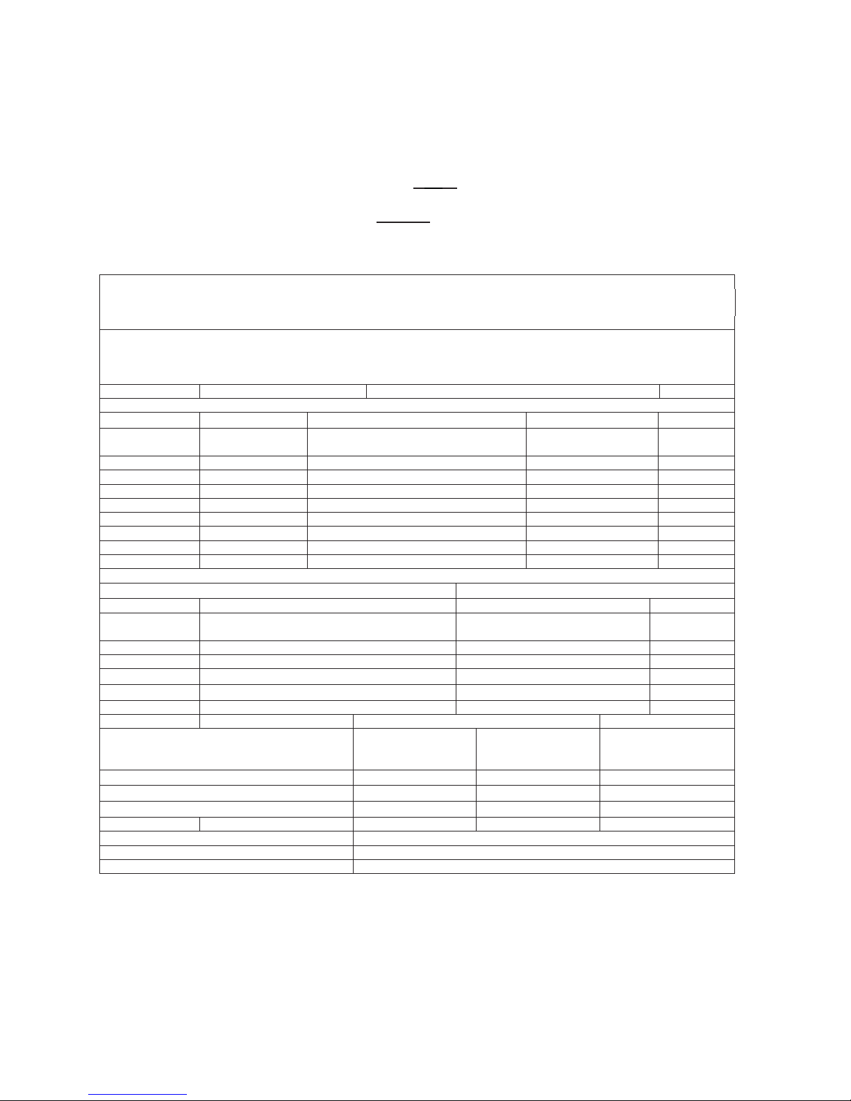
3.2 Technical Description
traP larenreG
Output Stage Protection: NA Temperature : Yes Short Circuit: Yes
srotacidnI
evitcA yalpsiD kcolC :rotacidnI edoM ybdnatS
ffO snruT DEL :edoM ybdnatS rewoP
Electrical Data
Normal
Limit
DSC: Y(Flat/POP/JAZZ
/ROCK/CLASSIC)
Channel Difference:
± 3dB
-
DBB: Y(ON/OFF) Hum (Vol
min
--- Vol
ma
x
-20dB) 150nW Bass: NA -
Treble: NA Channel Seperation: 1kHz/10kHz 40dB/35dB
%0.1 %8.0 lamixaM,DHT AN :ssenduoL
Signal to Noise Ratio(A-weighted): 77dBA 72dBA
Bd55 Bd06 :klatsorC
Amplification Reserve 3dB 2dB
Audio Inputputs
Audio Input Sensitivity(± 3dB) rated output power at 1kHz
Audio Output(*1)
Tuner FM 67.5kHz, Modulation (Limit:-6dB) Line Out(Left/Right) NA
2 ± Wm51 enohpdaeH )1 kcarT ,1 csiD oiduA( kcart Bd3- 3PM/DC
dB, RL = 16Ω
)SH0.2 (evawenis zHK1 Bd3- BSU
MP3_link(front)
500mV ---- 1000mV; Rin ≥ 22kΩ
Output
Power(*1)
At THD=10%, 1kHz
sinewave
MCM1050
(ROP,10%)
MCM1050
(Max Power,30%)
Main Operation for / all version (rms)
5W± 1dB
2X12W -1dB
Tuner output power(rms)
5W± 1dB
NA
Frequency Response(± 3dB)
60Hz-20kHz
Loudspeaker(Boxes): Separable speaker box Refer to package document of Speaker Box Assy
Speaker driver Impedance: Right/Left: 4Ω @ 40 Hz ~ 20kHz(-3db)
:refoowbuS
REMARKS:
Electrical Parameters are to be measured at Speaker Terminals across rated impedance Load(4ohm) with
Rated Input Signal in CD Mode setting in DBB/Loudness Off and Pre-eq at Flat unless specified otherwise.
*--- measure max volume power with 1V MP3-link input
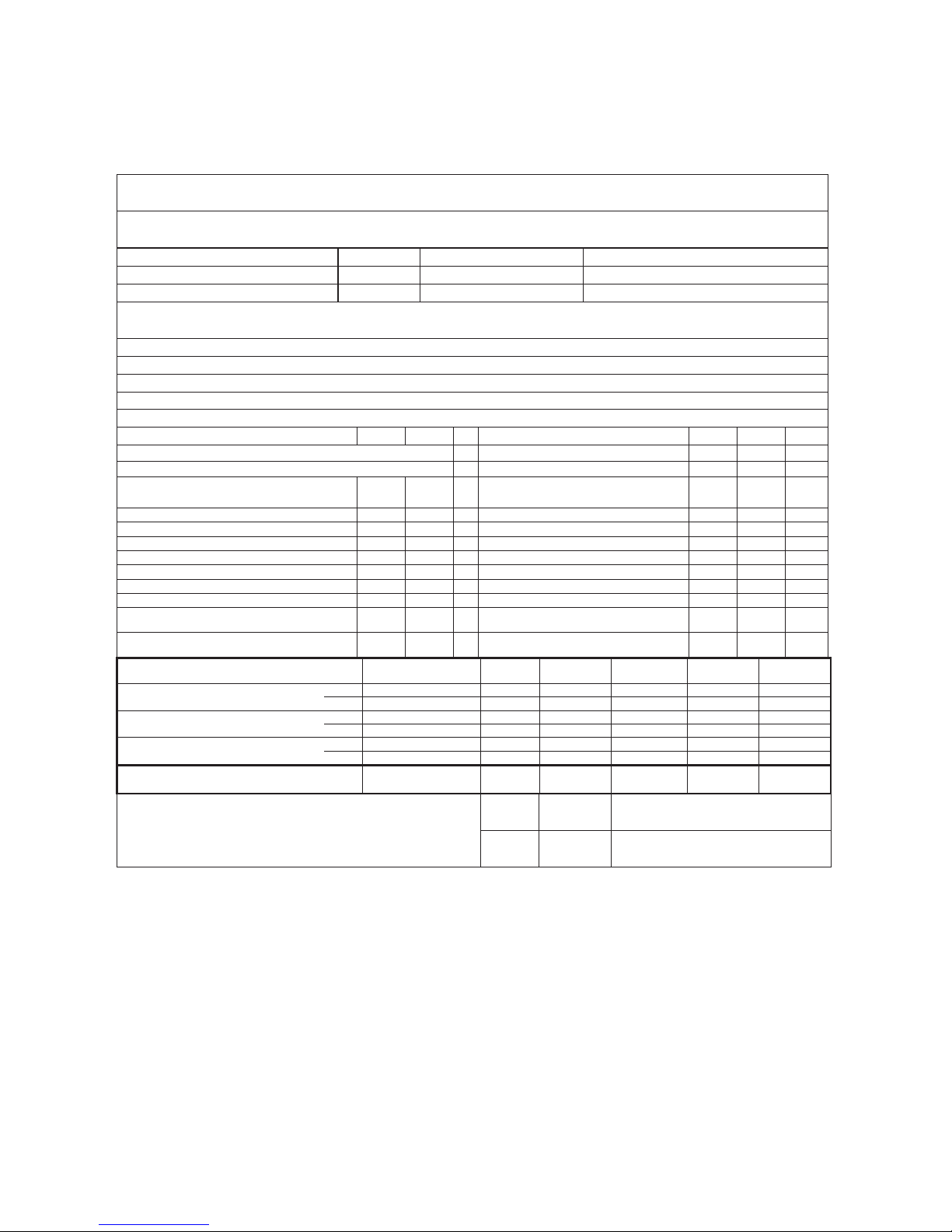
3.3 TUNER
FM use Silicon Lab Si4704/4705(w/RDS)
GENARAL PART
WAVE RANGE VERSION TOLERANCE TUNING GRID
FM 87.5 – 108.00 MHz /12 QUARTZ PRECISION 50kHz
FM 87.5 – 108.00 MHz /37 QUARTZ PRECISION 100kHz
AERIAL
FM : PIG TAIL ANT WIRE 75Ω
ELECTRICAL DATA
tinU timiL moN MF
fBd 62 02 tnioP gnitimiL Bd 3 -
14 53 )edom oerets ta(ytivitisneS gninuT hcraeS
Search time digital tuning
system.
- 60 S
zHM 7.01 FI
Bd 15 84 gniteiuQ Bd 64 - oeretS
54 05 muH noitaludoM
54 05 oitaR N/S
Bd 4- 0 esreveR noitacifilpmA
% 3 2 ) zHk 57.veD qrF ,Vm1 FR ( noitrotsiD
Overall Frequency Response: 63Hz –
12.5KHz
- ±3 dB
Channel separation:400 / 1000 / 5000 Hz.
RF input: 68 dBf
26/30/
20
20/26/
18
dB
Frequency (MHz)
Noise Limited
Sensitivity 26 dB
Image
Rejection
IF Rejection
Large Signal
Handling
Selectivity
S9/300 kHz
22 0001 46 03 81.moN MF
)1*( 81 005 54 52 22.miL 0.88
22 0001 46 03 81.moN MF
)1*( 81 005 54 52 22.miL 0.89
54 fBd 611 06 03 81.moN MF
52 fBd 801 56 52 22.miL 0.701
Units dBf DB dB mV/m dB
Susceptibility to unwanted signals(CPU,SMPS,AMP,DSP …):
Limited(d
B)
Normal
(dB)
Remark
-15dB -20dB Refer to selfpollution curve
1-8
Technical Specification and Connection Facilities

Laser Beam Safety Precautions
This Blu-Ray player uses a pickup that emits a laser beam.
The laser beam is emitted from the location shown in the figure. When checking the laser diode, be sure to keep
your eyes at least 30 cm away from the pickup lens when the diode is turned on. Do not look directly at the laser
beam.
CAUTION: Use of controls and adjustments, or doing procedures other than those specified herein, may result in
hazardous radiation exposure.
Location: Inside Top of Blu-Ray mechanism.
Do not look directly at the laser beam coming
from the pickup or allow it to strike against your
skin.
Drive Mechanism Assembly
Laser Beam Radiation
Laser Pickup
Turntable
2-1
 Loading...