

Page 1
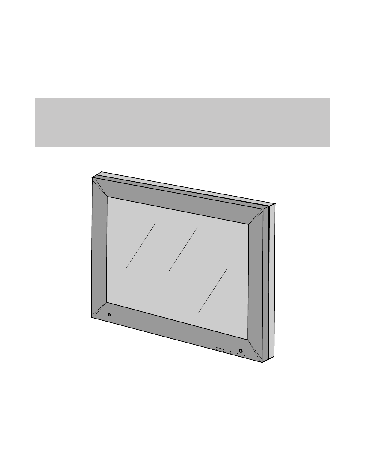
User’s Manual
m
e
nu
LCD 18” COLOR MONITOR
MCL1801 FAMILY
Copyright © 2002 FIMI S.r.l. Saronno - Italy
All rights are reserved. Reproduction in whole or in part is prohibited without the written consent of the copyright owner
Printed in Italy (Rev. 1.1)
Page 2
2
MCL1801
Copyright ©
This manual is copyrighted with all rights reserved. Under the copy rights law, this manual may not be
copied, in whole or part, without written consent of Philips. Under the law, copying includes translating into
another language or format.
The monitor described in this manual, has been certifi ed/registered by the safety agencies/regulatory authori-
ties as model n° :
FCC Notice
This equipment has been tested and found to comply with the limits for a class A digital device, pursuant to
Part 15 of FCC Rules. These limits are designed to provide reasonable protection against harmful interference
when the equipment is operated in a commercial environment.
This equipment generates, uses and can radiate radio frequency energy and , if not installed and used in
accordance to radio communications.
Operation of this equipment in a residential area is likely to cause harmful interference in which case the user
will be required to correct the interference at his own expense.
This monitor complies with the European community radio interference standard EN 55011 Class B.
Modifi cation
The FCC requires the user to be notifi ed that any changes or modifi cations made to this device that are not
expressly approved by the manufacturer may vold the user’s autority to operate the equipment.
Cables
Connections to this device must be made with shielded signals cables with metallic RFI/EMI connector hoods
to maintain compliace with FCC Rules and Regulations.
The lighting fl ash with arrowhead simbol is intend to alert the user of the presence of uninsulated “dangerous voltage”
within the product’s enclosure that may be suffi cient magnitude to constitute a risk of electrical shock to people.
The exclamation mark is intended to alert the user of the presence of important operating and maintenance (servicing)
instructions in literature accompanying the appliance.
CAUTION
RISK OF ELECTRICAL SHOCK
DO NOT OPEN
ATTENTION
RISQUE DE CHOC ELECTRIQUE
NE PAS OUVRIR
CAUTION: TO REDUCE THE RISK OF ELECTRICAL SHOCK.
DO NOT REMOVE COVER (OR BACK)
NO USER SERVICEABLE PARTS INSIDE
REFER SERVICING TO QUALIFIED SERVICE PERSONNEL
WARNING:
TO PREVENT DAMAGE WHICH MAY RESULT IN FIRE OR SHOCK AZARD, DO
NOT EXPOSE THIS APPLIANCE TO RAIN OR EXCESSIVE MOISTURE.
.
THE ENCLOSURE HAS TO BE CHECKED UPON COLLISION DAMAGE; REFER
TO QUALIFIED SERVICE PERSONNEL
Page 3

3
MCL1801
INTRODUCTION
The FIMI Medical Grade MCL1801 Medical is a color active matrix, liquid crystal display exclusively
designed for medical applications.
The monitor can be used for general medical viewing requiring high level color image quality, as well
as in the Control Stations of Patient Monitoring, with a resolution of 1280 x 1024, and can accept an
analogue signal input as well as a digital input.
The product is engineered to meet all stringent medical safety requirements, including UL2601.1,
CAN/CSA C22.2 No.601.1, EN-60601.1 and the product can be safely placed next to other sensitive
equipment with no risk of harmful interference.
Certifi cations of monitor also cover requirements for liquid ingress and current-leakage from power
supply.
The other key features of the MCL1801 are:
- long term luminance stability through an optional backlight stabilization circuit
- luminace stability vs the viewing angle
- contrast stability vs the viewing angle
- brightness uniformity
- automatic brightness control with backlight sensor and ambient light sensor
- internal automatic greyscale calibration (10 bit L.U.T.)
The tilt swivel base can be removed and the monitor uses a mounting plate that conforms to the
VESA mounting standard, that allows fl exible mounting options, including wall mounting and rolling
stands.
User controls are available through On-Screen Display.
Page 4

4
MCL1801
CONTENTS
TECHNICAL INFORMATION.............................................5
DIMENSIONS..........................................................................6
INSTALLATION
.....................................................................8
MOUNTING INSTRUCTION..............................................8
CONNECTING INSTRUCTION...........................................9
connecting AC power....................................................10
connecting analog video...............................................11
connecting digital video................................................11
connecting the optional touchscreen.............................12
INPUT INSTRUCTION.........................................................13
CONTROL PANEL DESCRIPTION....................................14
(OSD) ON SCREEN DISPLAY..............................................15
menu structure..............................................................15
OSD key functions.......................................................16
OSD controls...............................................................16
main menu................................................16
information...............................................17
image adjust..............................................17
horizontal position....................................18
vertical position........................................18
scale / center.............................................18
image Enhancement..................................18
ABC selection...........................................18
transfer function........................................19
advanced...................................................19
phase adjust..............................................20
clock adjust...............................................20
service.......................................................21
auto-setup options.....................................21
auto-setup on modest................................21
auto-clock feature.....................................22
auto-(Phase/Position)................................22
auto-(Clock/Position)................................22
auto-level .................................................22
restore factory preset................................23
language....................................................23
OSD setting..............................................23
OSD position............................................24
(OSD) vertical position............................24
OSD size..................................................25
OSD transparency....................................25
OSD timeout............................................25
video source.............................................25
keyboard option.......................................26
Page 5

5
MCL1801
TECHNICAL INFORMATION
Display Panel 18.1” (460mm) SXGA active matrix monocrome TFT/LCD
Supported Grayscale 8-bit
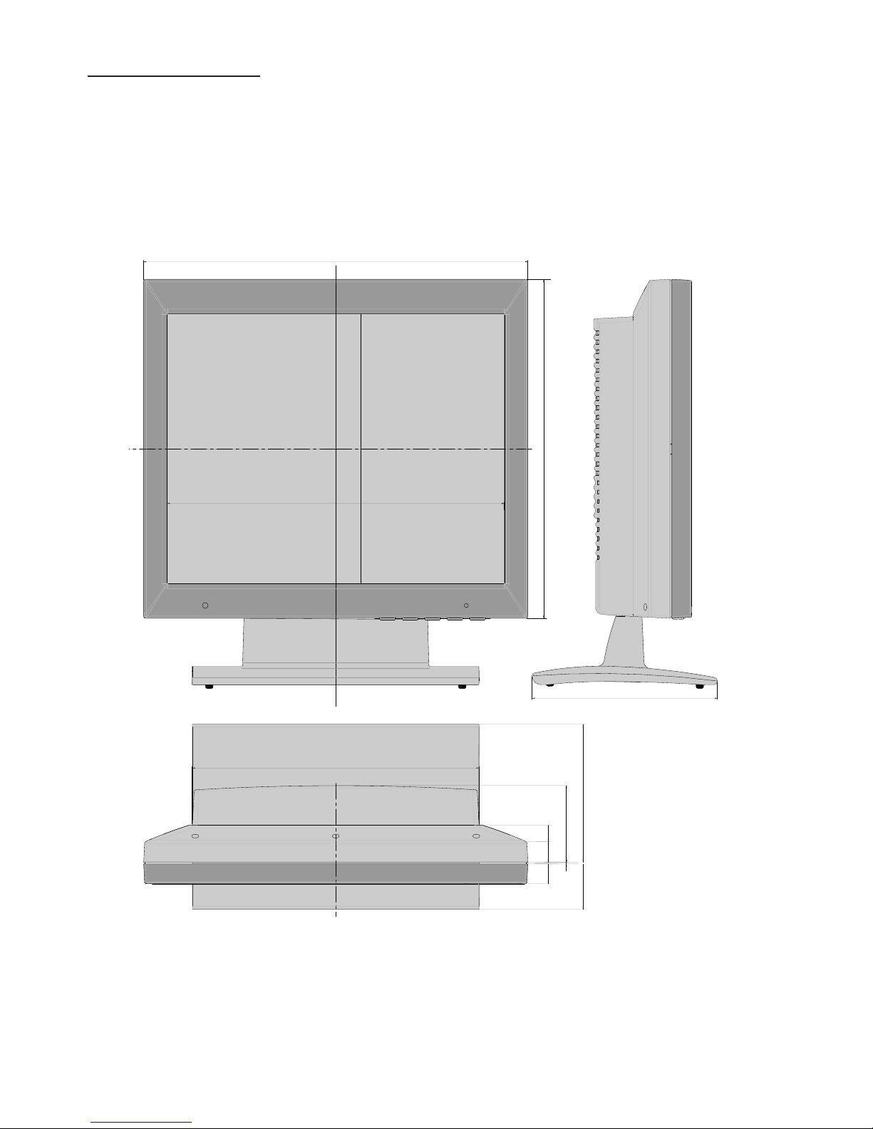
Dimensions Panel 410 x 362 x 105 mm. (width x height x depth.)
Weight 7,7 Kg ( panel ), 3,7 Kg ( pedestal )
Active display area 359,0 x 287,2 mm ( width x height )
Response Time 40 mS ( 10% to 90% rising + 90% to 10% falling )
Viewing Angle ± 85° typ. horizontal or vertical ( contrast ratio ≥ 15 )
Contrast Ratio 400 : 1 typ.
White luminance 200 cd/m
2
Pixel Pitch 0,2805 (one triad) x 0,2805 mm ( width x height )
Video interface Analog Input: DSUB-15 connection for Separate Sync Video Signal or
SOG Video Signal.
Digital Input: DVI-D connection for TMDS signal link standard
version.
Scanning Frequency Max pixel clock 135MHz
Power Consumption ≤ 70 W
Power Supply From 90 to 264 Vac , 50 -60 Hz
Operation Temperature +10 to +45 °C
Storage Temperature -20 to +60 °C
Humidity 80% ( Maximum Wet-Bulb should be 39 °C and No condensation )
Shock Half sine wave: 50G 11msec. ;X+/-, Y+/-, Z+/- (total 6 Directions), Each
two time shock.
Page 6
6
MCL1801
22.2
17.6
306.02
1.5
21.3
82
288.2
360
197.78
410
362
48.7
147.58
DIMENSIONS
Page 7
7
MCL1801
29
181
205 205
100
100
117
117
181
71
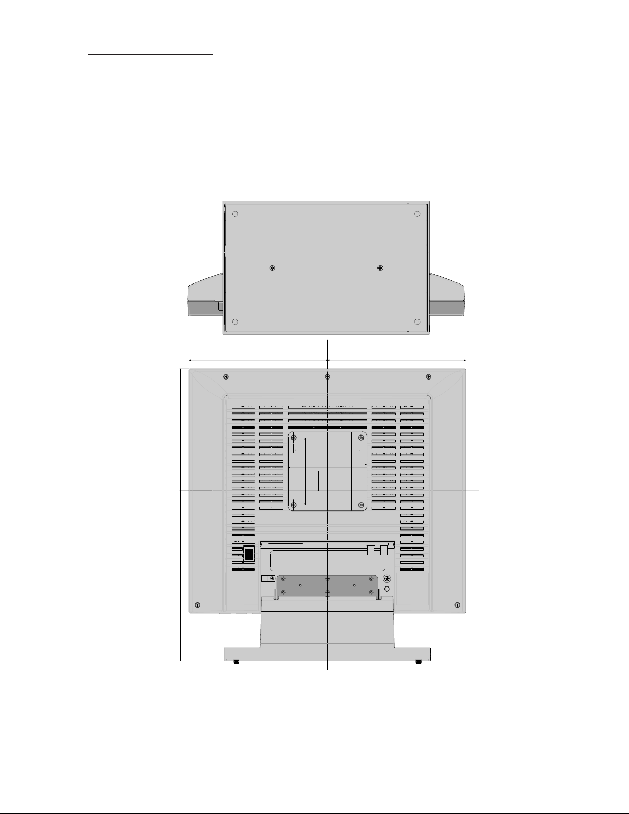
DIMENSIONS
Page 8
8
MCL1801
INSTALLATION
Before unpacking the monitor , prepare a suitable workspace. You need a stable and level surface near a
grounded wall outlet in an area that is relatively free of glare from sunlight or other sources of bright light.
The monitor is cooled by two internal fans. For best performance, do not block the cooling vents.
NOTE: before istalling this monitor, please refer to the user’s guides of your computer
and video adapter to make sure if these equipments require any change of setting.
Positioninig
WARNING:
WHEN POSITIONING THIS EQUIPMENT, ENSURE THAT THE MAINS PLUG AND SOCKET ARE
EASILY ACCESSIBLE
While unpacking the monitor, inspect it and other package contents for shipping damage that
could cause a fi re or shock hazard. immediately report any shipping damage to the carrier or
transportation company, and contact customer service for assistance. keep all packing material
in case you need to ship, store or return the monitor.
After unpacking the monitor, make sure the following items are included:
● Monitor
● Mains cord set 1,8-meter (USA version)
● Mains cord set 1,8-meter (EU version)
● Signal cable 1,8-meter (DB15 / DB15)
● This user’s manual
If you ordered the monitor with the resistive touchscreen option, the following items should
also be included:
● User’s manual of touchscreen
● Touchscreen cable
PEDESTAL (standard)
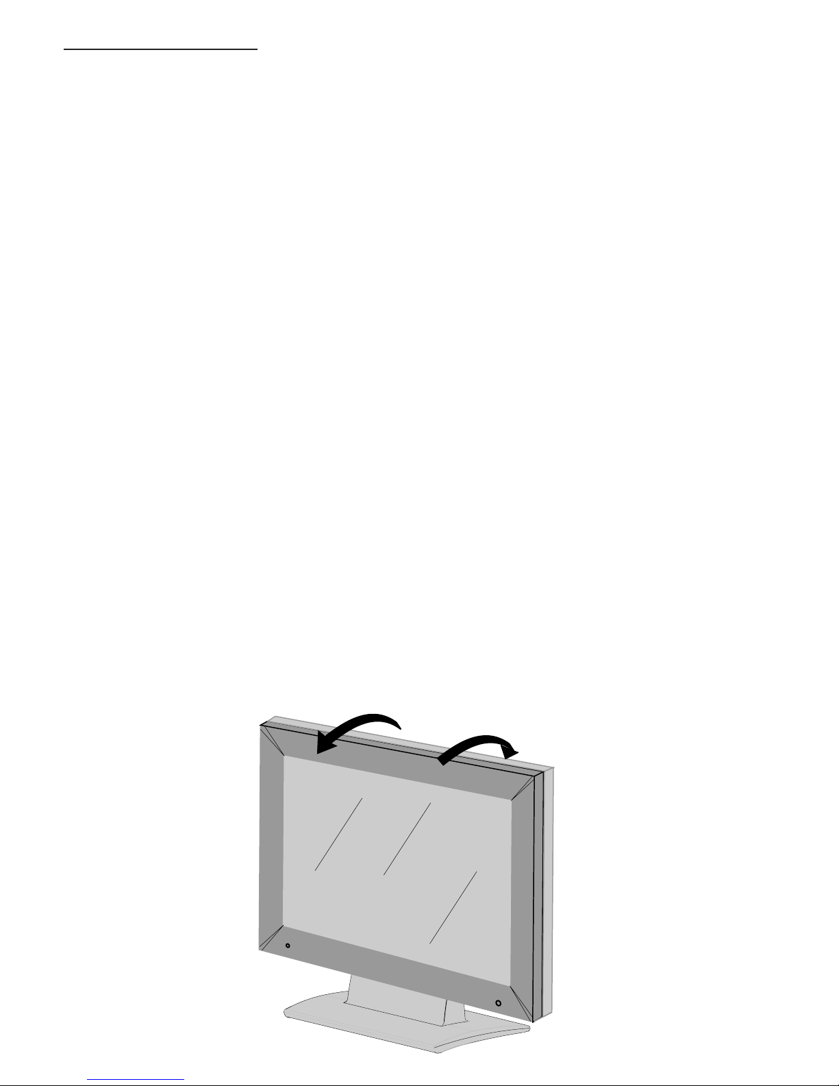
With the built-in pedestal you can tilt the monitor for a most comfortable viewing angle
as
shown in fi gure 8a.
5°
15°
fi g. 8a
Page 9
9
MCL1801
I
O
ARM VESA PLATE
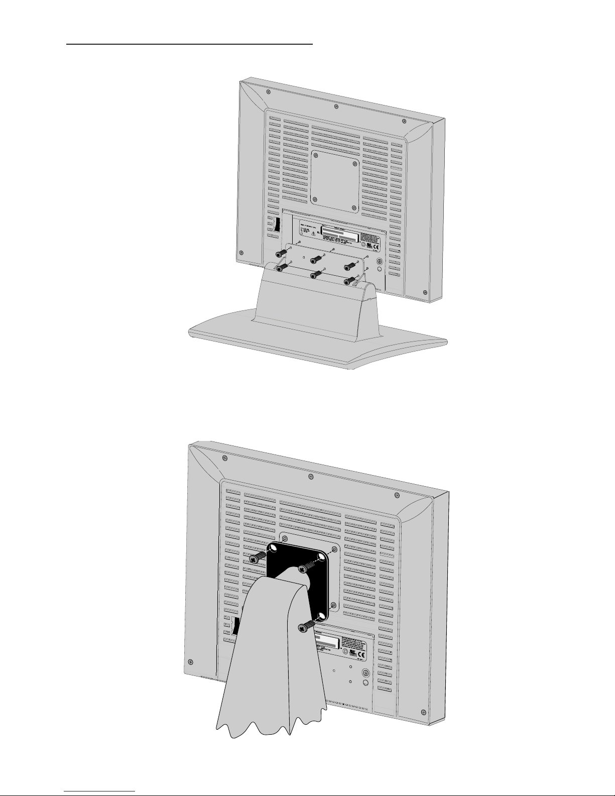
An arm with VESA (100x100) interface must be fi xed at monitor with N° 4 screws M4x10 as shown in
fi gure 9b.
MOUNTING INSTRUCTION
I
O
The pedestal must be fi xed at monitor with N° 6 screws M3x10 (included into the BOX) as shown in
fi gure 9a.
PEDESTAL STANDARD (OPTIONAL)
fi g. 9a
fi g. 9b
Page 10
10
MCL1801
I
O
CONNECTING INSTRUCTION
CONNECTING AC POWER
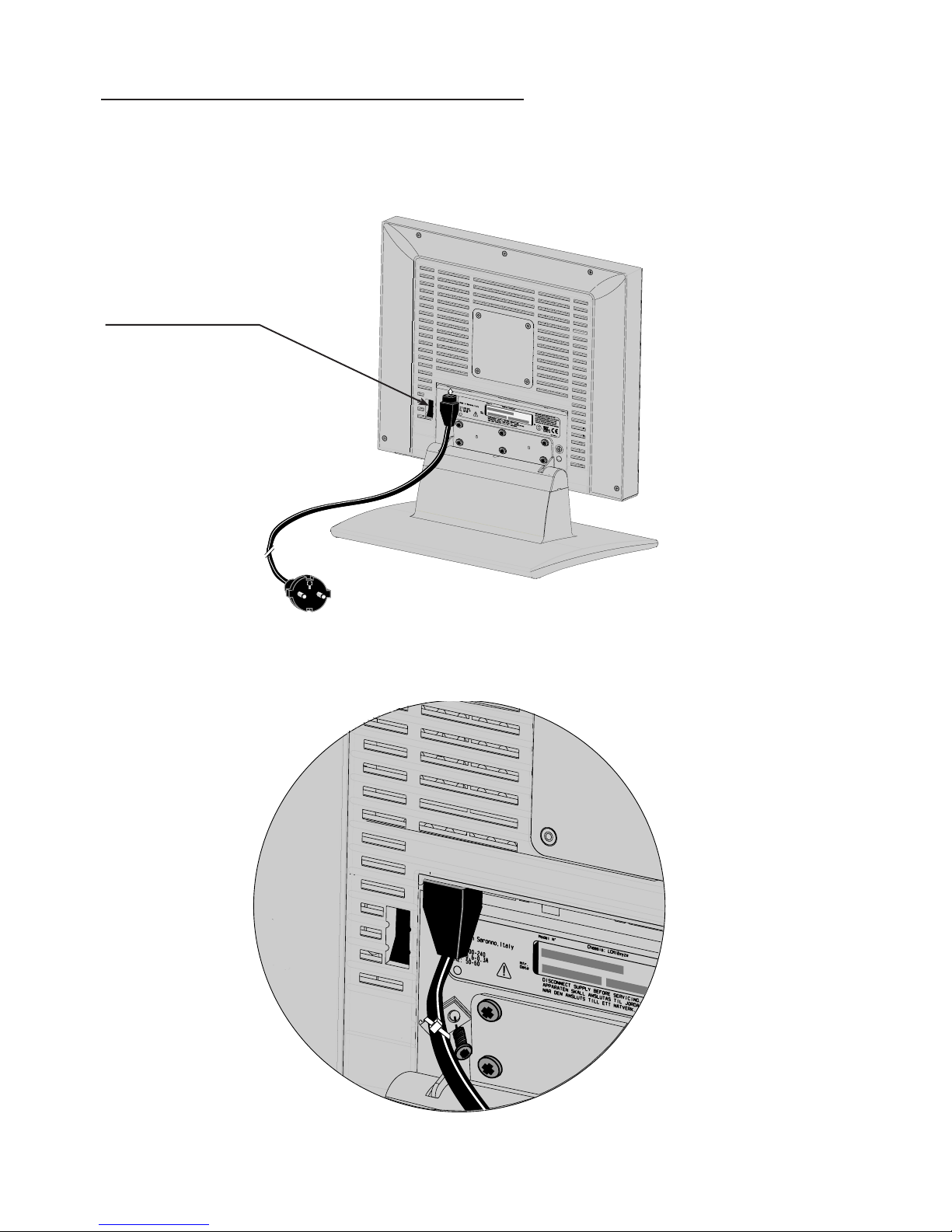
Plug the receptacle and of the cord set into the AC power adapter, then plug the power connector of the adapter
into the power port on the monitor.
This power port is located on the back of the monitor (see fi g. 10a).
fi g.10a
I
O
fi g 10b
The power cord set can be fi xed to cabinet with proper cable clamp and screw (see fi g. 10b)
Insert the plug end of the power cord into a grounded wall outlet. For added protection, use a surge protector
between the AC adapter and the electrical wall outlet to prevent sudden current variations from reaching
the monitor
MAINS SWITCH
Page 11
11
MCL1801
CONNECTING ANALOG VIDEO (SXGA)
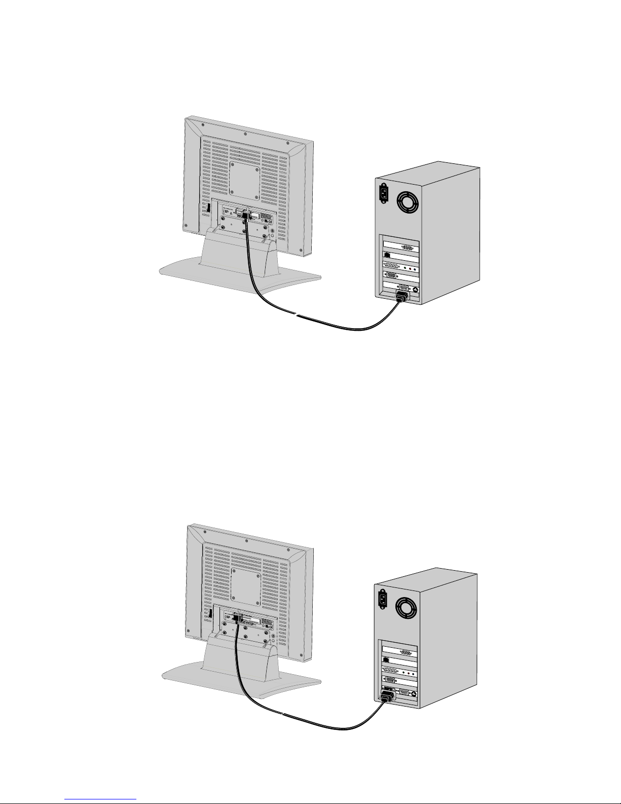
With the power the computer and the monitor turned off, connect the supplied video cable from the monitor
to the computer’s video port (see fi g. 11a)
G
R
B
I
O
fi g. 11a
Make sure the video cable connector is securely connected to the video port on your computer.
Turn the monitor on fi rst, and then turn on the computer.
fi g. 11b
CONNECTING DIGITAL VIDEO (DVI)
With the power the computer and the monitor turned off, connect the supplied video cable from the monitor
to the computer’s video port (see fi g. 11b)
G
R
B
I
O
Page 12
12
MCL1801
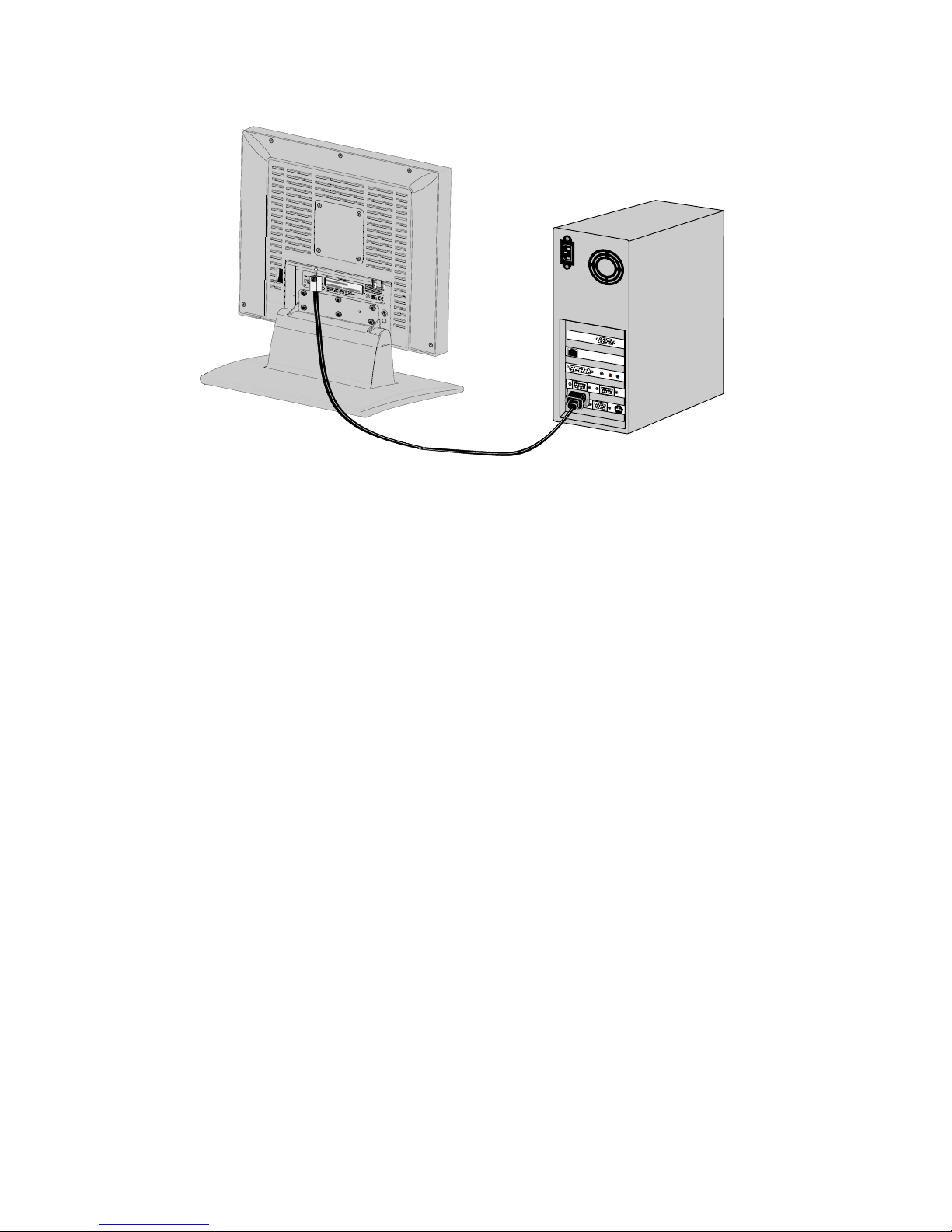
CONNECTING TOUCHSCREEN (OPTIONAL)
If your monitor has this optional feature, connect the monitor’s RJ11-4 serial port to the computer’s 9-pin
RS-232 serial port using the proper cable (see fi g. 12a)
fi g. 12a
NOTE: Follow the instructions included on the enclosed CD for installing the Touchscreen drivers on
your system. Following driver software installation, calibrate your Touchscreen to the system following the
procedure described on the enclosed CD.
I
O
G
R
B
Page 13
13
MCL1801
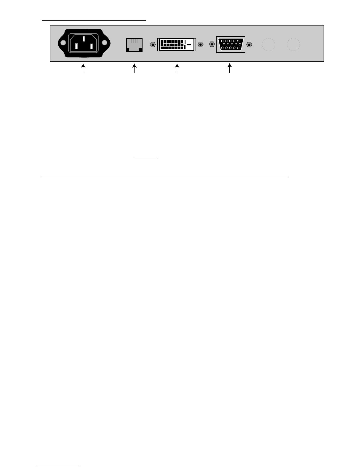
AC INLET
MAINS SOCKET
RS232
or
TOUCHSCREEN
DVI-INPUT
VIDEO-INPUT
XVGA
INPUT INSTRUCTION
fi g.13a
AC INLET (Meet IEC 320/CEE 22 STANDARD)
110/220Vdc
RS232 / TOUCHSCREEN Connector (RJ11-4)
Pin 1 : RS232 Rx
Pin 2 : RS232 Tx
Pin 3 : ENABLE (Only with touch screen)
Pin 4 : GND
Note: When the option touchscreen is used, the RS232 monitor control is not available.
DVI INPUT Connector (Microcross™ DVI-D female connector)
Pin 1 : D2_RX - (T.M.D.S.) Pin 13 : N.C.
Pin 2 : D2_RX + (T.M.D.S.) Pin 14 : +5V Power
Pin 3 : GND (Data 2 shield) Pin 15 : GND
Pin 4 : N.C. Pin 16 : Hot Plug Detect
Pin 5 : N.C. Pin 17 : D0_RX - (T.M.D.S.)
Pin 6 : SCL (For DDC) Pin 18 : D0_RX + (T.M.D.S.)
Pin 7 : SDA (For DDC) Pin 19 : GND (Data 0 shield)
Pin 8 : N.C. Pin 20 : N.C.
Pin 9 : D1_RX - (T.M.D.S.) Pin 21 : N.C.
Pin 10 : D1_RX + (T.M.D.S.) Pin 22 : GND (Clock shield)
Pin 11 : GND (Data 1 shield) Pin 23 : CK_RX + (T.M.D.S.)
Pin 12 : N.C. Pin 24 : CK_RX - (T.M.D.S.)
VIDEO INPUT XVGA Connection (DSUB15 female connector)
Pin 1 : R-in Pin 9 : N.C.
Pin 2 : G-in Pin 10 : GND
Pin 3 : B-in Pin 11 : N.C.
Pin 4 : N.C. Pin 12 : SDA (For DDC option)
Pin 5 : N.C. Pin 13 : H.S.-in
Pin 6 : GND Pin 14 : V.S.-in
Pin 7 : GND Pin 15 : SCL (For DDC option)
Pin 8 : GND
Page 14
14
MCL1801
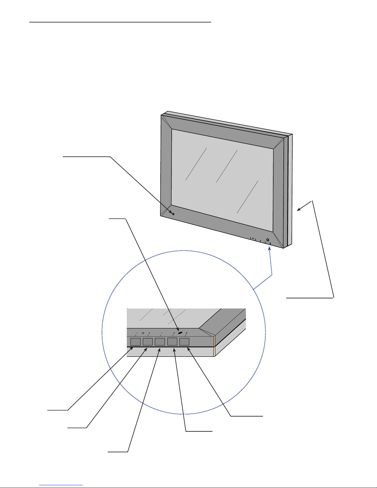
me
nu
menu
Menu select -
Enter
LED
CONTROL PANEL DESCRIPTION
On the front bottom side part of the unit the following controls are placed:
- BRIGHTNESS ADJ-
- BRIGHTNESS ADJ+
- MENU SELECT - / BRIGHTNESS Recall to 200 Cd/m²
- MENU SELECT +
- ENTER (Store/Source-Select)
fi g. 14a
Brightness
Adjust -
Brightness
Adjust +
Menu select +
GREEN= 200 cd/m² / Power-on
RED < 200 cd/m²
ORANGE= Stand-by
Power Switch
Light sensor
Page 15

15
MCL1801
(OSD) ON SCREEN DISPLAY
MENU STRUCTURE
MAIN MENU
│
├───── INFORMATION
│ ├───── CODE VERSION
│ └───── EXIT
│
├───── IMAGE ADJUST
│ ├───── HORIZONTAL POSITION
│ ├───── VERTICAL POSITION
│ ├───── SCALE / CENTER ─────┐
│ │ ├───── FULL SCREEN
│ │ ├───── MAINTAIN ASPECT RATIO
│ │ └───── CENTER
│ ├───── IMAGE ENHANCEMENT
│ │ ├───── ABC SELECTION
│ │ │ ├─────────────ABC OFF
│ │ │ ├─────────────ABC REDUCED
│ │ │ └─────────────ABC FULL
│ │ ├───── TRANSFER FUNCTION
│ │ │ ├─────────────6500° K
│ │ │ ├─────────────7600° K
│ │ │ ├─────────────9300° K
│ │ │ ├─────────────DICOM
│ │ │ └─────────────TG3
│ │ └───── EXIT
│ ├───── ADVANCED ───────┐
│ │ ├───── PHASE ADJUST
│ │ ├───── CLOCK ADJUST
│ │ ├───── SERVICE ─┐
│ │ │ ├─────────────OFFSET RED ADJUST
│ │ │ ├─────────────OFFSET GREEN ADJUST
│ │ │ ├─────────────OFFSET BLUE ADJUST
│ │ │ ├─────────────GAIN RED ADJUST
│ │ │ ├─────────────GAIN GREEN ADJUST
│ │ │ ├─────────────GAIN BLUE ADJUST
│ │ │ ├─────────────STORE VIDEO
│ │ │ └─────────────EXIT
│ │ ├───── AUTO-SETUP OPTIONS
│ │ │ ├─────────────AUTO-SETUP ON MODESET
│ │ │ │ ├────────────── ENABLED
│ │ │ │ ├────────────── DISABLED
│ │ │ │ └────────────── ONLY ONCE
│ │ │ ├─────────────AUTO-CLOCK FEATURE
│ │ │ │ ├────────────── ENABLED
│ │ │ │ └────────────── DISABLED
│ │ │ └─────────────EXIT
│ │ ├───── AUTO-(PHASE/POSITION)
│ │ ├───── AUTO-(CLOCK/POSITION)
│ │ ├───── AUTO-LEVEL
│ │ ├───── RESTORE FACTORY PRESETS
│ │ └───── EXIT
│ └───── EXIT
│
├───── LANGUAGES
│ ├───── ENGLISH
│ ├───── FRANCAIS
│ ├───── DEUTSCH
│ ├───── ESPANOL
│ └───── ITALIANO
│
├───── OSD SETTING
│ ├───── OSD POSITION ──────┐
│ │ ├───── HORIZONTAL POSITION
│ │ ├───── VERTICAL POSITION
│ │ └───── EXIT
│ ├───── OSD SIZE ────────┐
│ │ ├───── NORMAL
│ │ └───── DOUBLE
│ ├───── OSD TRANSPARENCY
│ ├───── OSD TIMEOUT ──────┐
│ │ ├───── 10 Sec.
│ │ ├───── 20 Sec.
│ │ ├───── 30 Sec.
│ │ ├───── 45 Sec.
│ │ ├───── 60 Sec.
│ │ ├───── 90 Sec.
│ │ ├───── 120 Sec.
│ │ └───── DISABLED
│ └───── EXIT
│
├───── VIDEO SOURCE
│ ├───── DSUB-SOG (GREEN INPUT)
│ ├───── DVI
│ ├───── DSUB (HT. AND VT. SYNC.)
│ └───── EXIT
│
├───── KEYBOARD OPTION
│ ├───── KEYBOARD UNLOCK
│ └───── KEYBOARD LOCK
│
└───── EXIT
Page 16
16
MCL1801
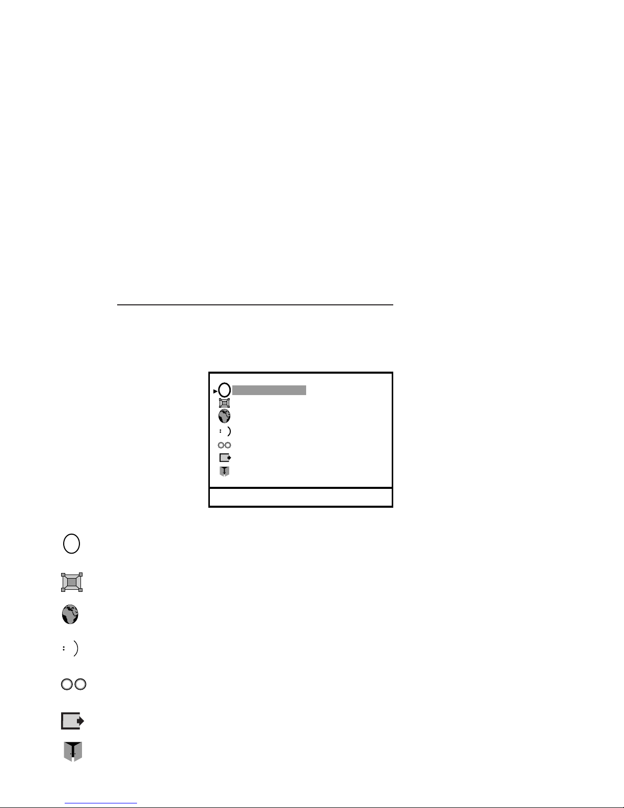
E
Video Source
Image Adjust
Languages
Information
Exit
OSD Settings
i
Keyboard Option
1024 x 768 @ 60 Hz - DSUB
6.0.0 OSD (ON SCREEN DISPLAY) CONTROLS
6.1.0 Main manu
After the activation of OSD Main Menu appears the following window
OSD KEY FUNCTIONS
Function Key Description
Enter N
It activates the OSD MAIN MENU if this is not active, otherwise selects and
executes a desired OSD Special Function.
Adjust - Menu - When main menu or sub-menu is active, it allows to move or scroll to the
previous (upper) item or decrement the magnitude of the parameter.
Adjust + Menu + When main menu or sub-menu is active, it allows to move or scroll to the
previous (down) item or increment the magnitude of the parameter.
Pressing “Enter” key the MAIN MENU highlight selection is the fi rst Sub-menu item “Video Information”
Pressing “Menu +” or “Menu -” key, the highlight selection of menu item moves downward/ upward
Pressing “Enter” key, the current menu window disappears and is replaced by the new sub-menu windows.
Information It shows the hardware and fi rmware status (operating hours and release number)
Image Adjust To adjust the picture when it is not correct
Languages To select the correct language
OSD Settings To adjust the OSD options (position, attribute activity delay)
Video Source To select the correct video input source
Keyboard Option To select the keyboard status.
Exit To exit from “MAIN MENU” .
i
Page 17
17
MCL1801
6.2.0 Information
1) Press Enter button when the Information is highlighted on Main menu.
The Information window appears.
MCL1801 Model
Ver CO.62-DO.62 Firmware Release
h00002 Operating Hours
c1B Video timing number
3) To press Enter buttton to return to Main Menu.
Horizontal Position
Vertical position
Scale / Center
Exit
Image Enhancement
Image Adjust
Advanced
6.3.0 Image Adjust
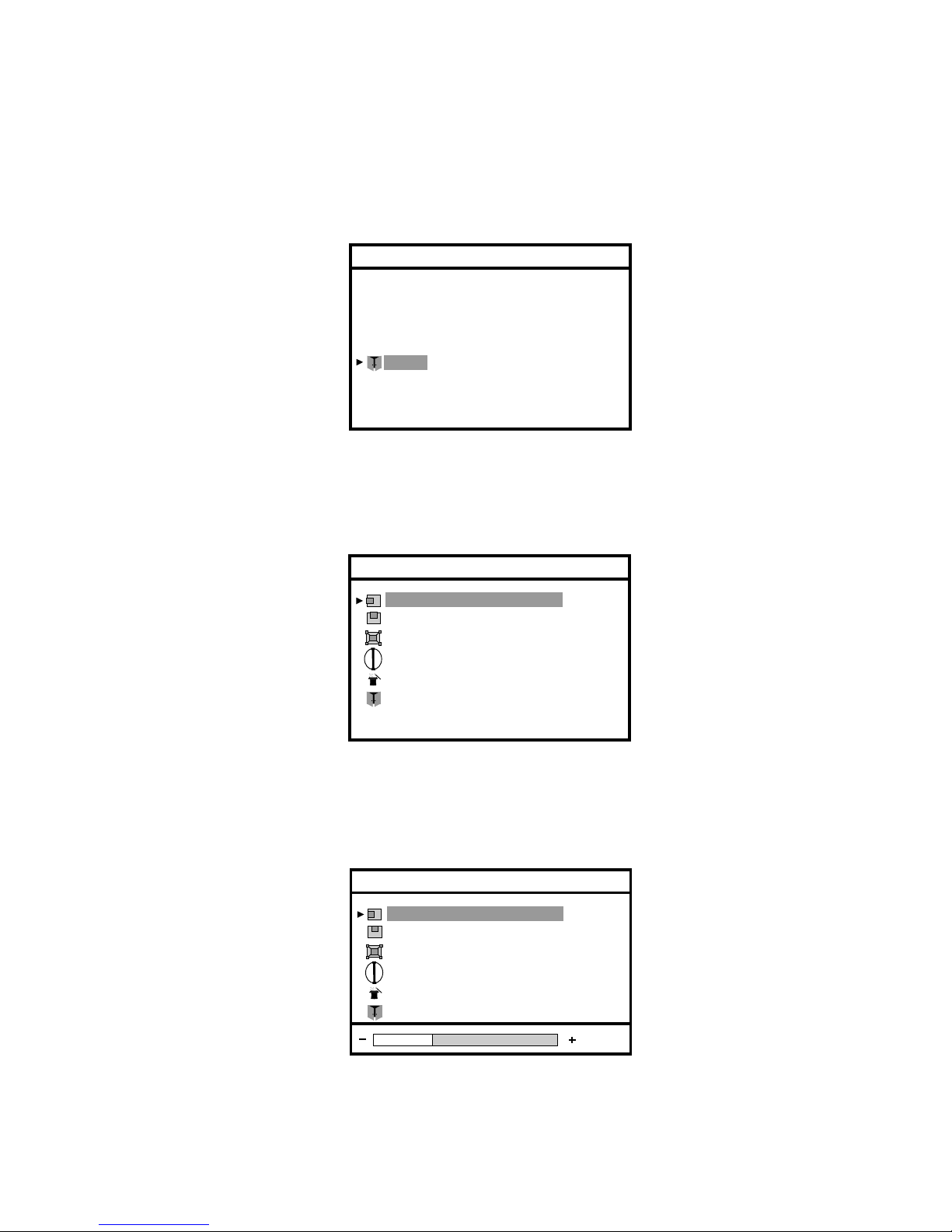
1) Press Enter button when the Image Adjust is highlighted on Main Menu.
The Image Adjust window appears.
6.3.1 Horizontal Position
1) Press Enter button when the Horizontal Position is highlighted on Image Adjust.
The Horizontal Position bar appears.
Horizontal Position
Vertical position
Scale / Center
Exit
Image Enhancement
Image Adjust
Advanced
2) Press Adjust + or Adjust - button to move the image to the left or right
3) When the position is adjusted, press the Enter button to return to Image Adjust window
4) To select Exit and press again Enter buttton to return to Main Menu or select Vertical Position.
FIMI-Philips
MCL1801
Exit
Ver CO.62-DO.62 h00002 c1B
Information
Page 18
18
MCL1801
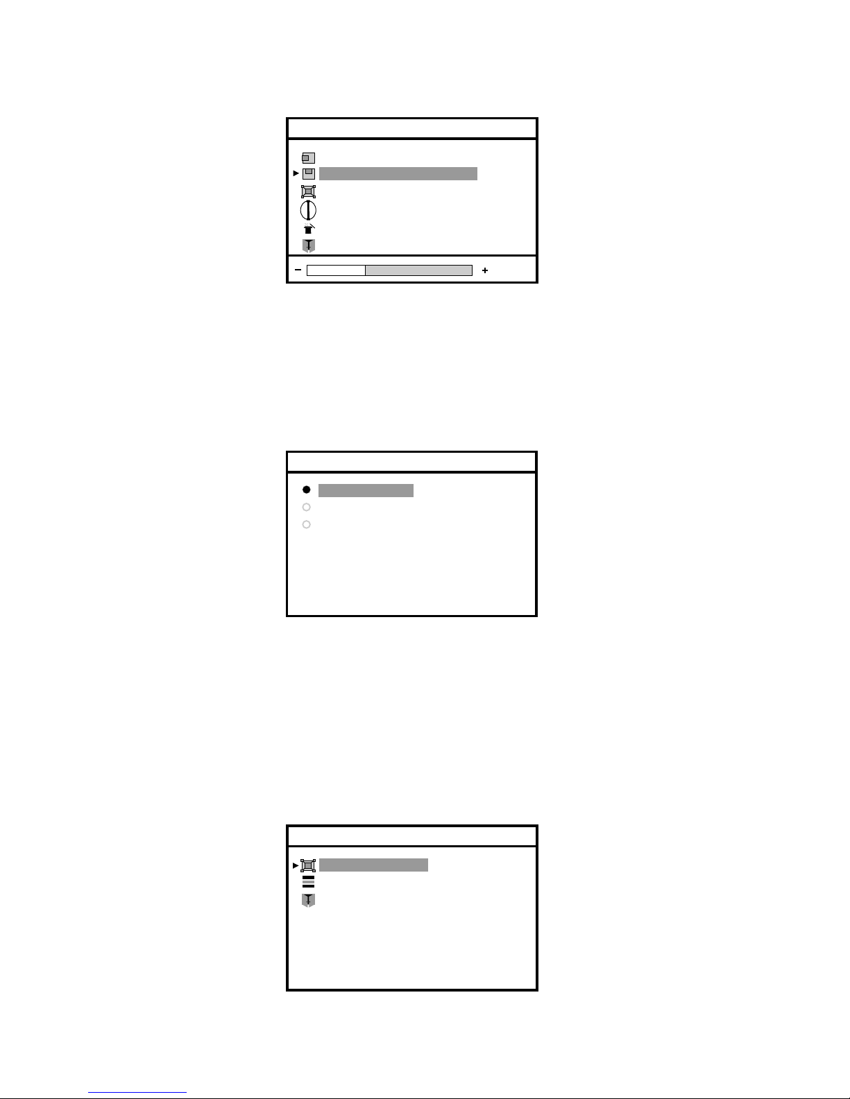
6.3.2 Vertical Position
1) Press Enter button when the Vertical Position is highlighted on Image Adjust.
The Vertical Position bar appears.
Horizontal Position
Vertical position
Scale / Center
Exit
Image Enhancement
Image Adjust
Advanced
2) Press Adjust + or Adjust - button to move the image to the up or down
3) When the position is adjusted, press the Enter button to return to Image Adjust window
4) To select Exit and press again Enter button to return to Main Menu or select Scale / Center
ABC selection
Transfer Function
Exit
Image Enhancement
Full Screen
Maintain Aspect Ratio
Center
Scale / Center
6.3.3 Scale / Center
1) Press Enter button when the Scale / Center is highlighted on Image Adjust.
The Scale / Center window appears.
The ON SCREEN DISPLAY shows the three modes available.
The default is Full Screen, but you can select Maintain Aspect Ratio or Center.
2) Press the Adjust + or Adjust - button to change the video mode, the choosen mode is highlighted.
3) Press the Enter button to confi rm your selection and return to Image Adjust window
6.3.4 Image Enhancement
1) Press Enter button when the Image Enhancement is highlighted on Image Adjust.
The Image Enhancement window appears.
2) Press the Menu + or Menu - button until the desired item is highlighted.
Page 19
19
MCL1801
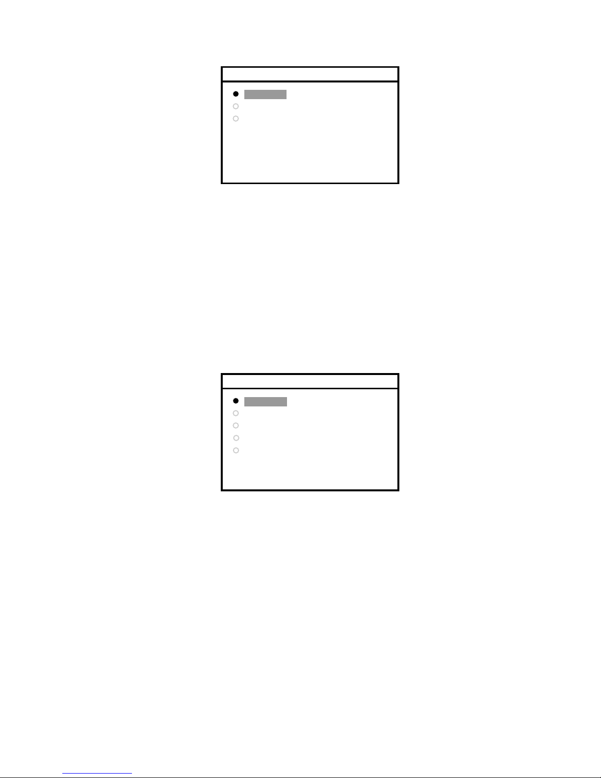
6.3.5 ABC Selection
1) Press Enter button when the ABC Selection is highlighted on Image Enhancement
The ABC Selection window appears.
ABC Off
ABC Reduced
ABC Full
ABC Selection
2) Press the Adjust + or Adjust - button until the desired item is highlighted.
- ABC off
Manual back light control regulated by panel button from 80 cd/m² to 200 cd/m²
- ABC full
Automatic control of back light, the back light is function of ambient light and follow a semilogaritmic
courve from 80 cd/m² (at 1 lux) to 200 cd/m² (at 1000 lux).
-ABC reduced
The same as ABC full but with full scale of 140 cd/m² (at 1000 lux).
3) Press the Enter button to confi rm your selection and return to Image Enhancement window
6500° K
7600° K
9300° K
Transfer Function
DICOM
TG3
6.3.7 Advanced
1) Press Enter button when the Adavanced is highlighted on Main Menu
The Advanced window appears.
6.3.6 Transfer Function
1) Press Enter button when the Transfer Functiopn is highlighted on Image Enhancement
The Transfer Function window appears.
2) Press the Adjust + or Adjust - button until the desired item is highlighted.
Five colour temperature preset modes:
- 6500° K
DTP
- 7600° K
Photo retouch
- 9300° K
CAD/CAM
- DICOM
The output curve follows the DICOM curve
- TG3
The output curve is the same as PMS standard monitor.
3) Press the Enter button to confi rm your selection and return to Image Enhancement window
Page 20
20
MCL1801
Phase Adjust
Clock Adjust
Service
Exit
Auto-Setup Options
Advanced
Auto-(Phase/Position)
Auto-Level
Restore Factory Presets
Auto-(Clock/Position)
Phase Adjust
Clock Adjust
Service
Exit
Auto-Setup Options
Advanced
Auto-(Phase/Position)
Auto-Level
Restore Factory Presets
Auto-(Clock/Position)
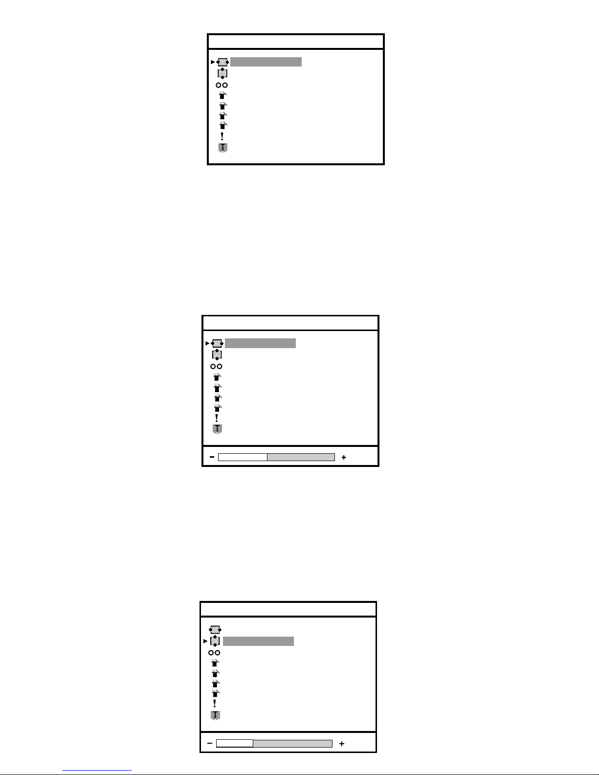
6.3.8 Phase Adjust
1) Press Enter button when the Phase Adjust is highlighted on Advanced.
The Phase Adjust bar appears.
2) Press Adjust + or Adjust - button to adjust the quality image
Note: It is necessary to use video pattern dedicated to obtain the best result
3) When the position is adjusted, press the Enter button to return to Advanced window
4) Select Exit and press again Enter button to return to Image Adjust or select Clock Adjust.
Phase Adjust
Clock Adjust
Service
Exit
Auto-Setup Options
Advanced
Auto-(Phase/Position)
Auto-Level
Restore Factory Presets
Auto-(Clock/Position)
2) Press the Menu + or Menu - button until the desired source is highlighted.
6.3.9 Clock Adjust
1) Press Enter button when the Clock Adjust is highlighted on Advanced.
The Clock Adjust bar appears.
2) Press Adjust + or Adjust - button to adjust the quality image
Note: It is necessary to use video pattern dedicated to abtain the best result
3) When the position is adjusted, press the Enter buton to return to Advanced window
4) To select Exit and press again Enter button to return to Image Adjust or select Service.
Page 21
21
MCL1801
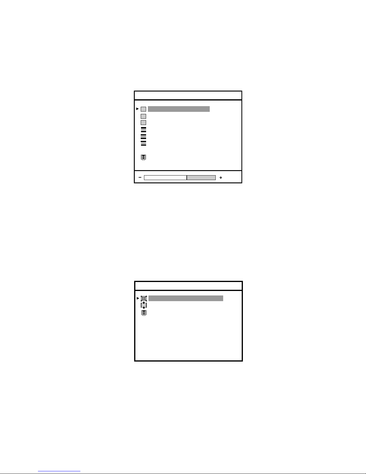
Auto-Setup On Modeset
Auto-Clock Feature
Exit
Auto-Setup Options
6.3.10 Service
1) Press Enter button when the Service is highlighted on Advanced.
The Service window appears.
2) Press Menu + or Menu - button until the desired item is highlighted and press Enter.
3) Press Adjust + or Adjust - button to adjust the quality image
4) When the item is adjusted, press the Enter button to return to Service window
5) Offest and Gain are items to use to calibrate the video signal (valid only for DSUB / DSUB/SOG video source).
When the calibration is OK it is necessary to execute the store operation to preserve the new values.
Press Enter buton when the Store Video is highlighted.
6) Select Exit and press again Enter button to return to Advanced or select Auto-Setup Options.
6.3.11 Auto-Setup Options
1) Press Enter button when the Auto-Setup Options is highlighted on Advanced.
The Auto-Setup Options window appears.
2) Press Menu + or Menu - button to select automatic options.
Auto-Setup Options and Auto-Clock feature defi ne the modality of Auto-Adjust of the video image when the video
timing is recognized.
3) Select Exit and press again Enter button to return to Advanced or select Auto-Level.
6.3.12 Auto-Setup On Modest
1) Press Enter button when the Auto-Setup On Modest is highlighted on Auto-Setup Options.
The Auto-Setup On Modest window appears.
2) Press Adjust + or Adjust - button until the desired item is highlighted
3) Press the Enter button to confi rm your selection and return to Auto-Setup Options window
Store Video
Offset Red Adjust
Offset Green Adjust
Offset Blue Adjust
Exit
Service
16
Gain Red Adjust
Gain Blue Adjust
Gain Green Adjus
Page 22
22
MCL1801
6.3.14 Auto-(Phase/Position)
1) Press Enter button when the Auto-(Phase/Position) is highlighted on Advanced.
To perform an automatic adjustmant of the video image.
Valid only DSUB-SOG and DSUB video source.
2) Select Exit and press again Enter button to return to Image Adjust or select Auto-(Clock/Position).
6.3.16 Auto-Level
1) Press Enter button when the Auto-Level is highlighted on Advanced.
To perform an automatic calibration of the video signal.
Valid only DSUB-SOG and DSUB video source.
2) Select Exit and press again Enter button to return to Image Adjust.
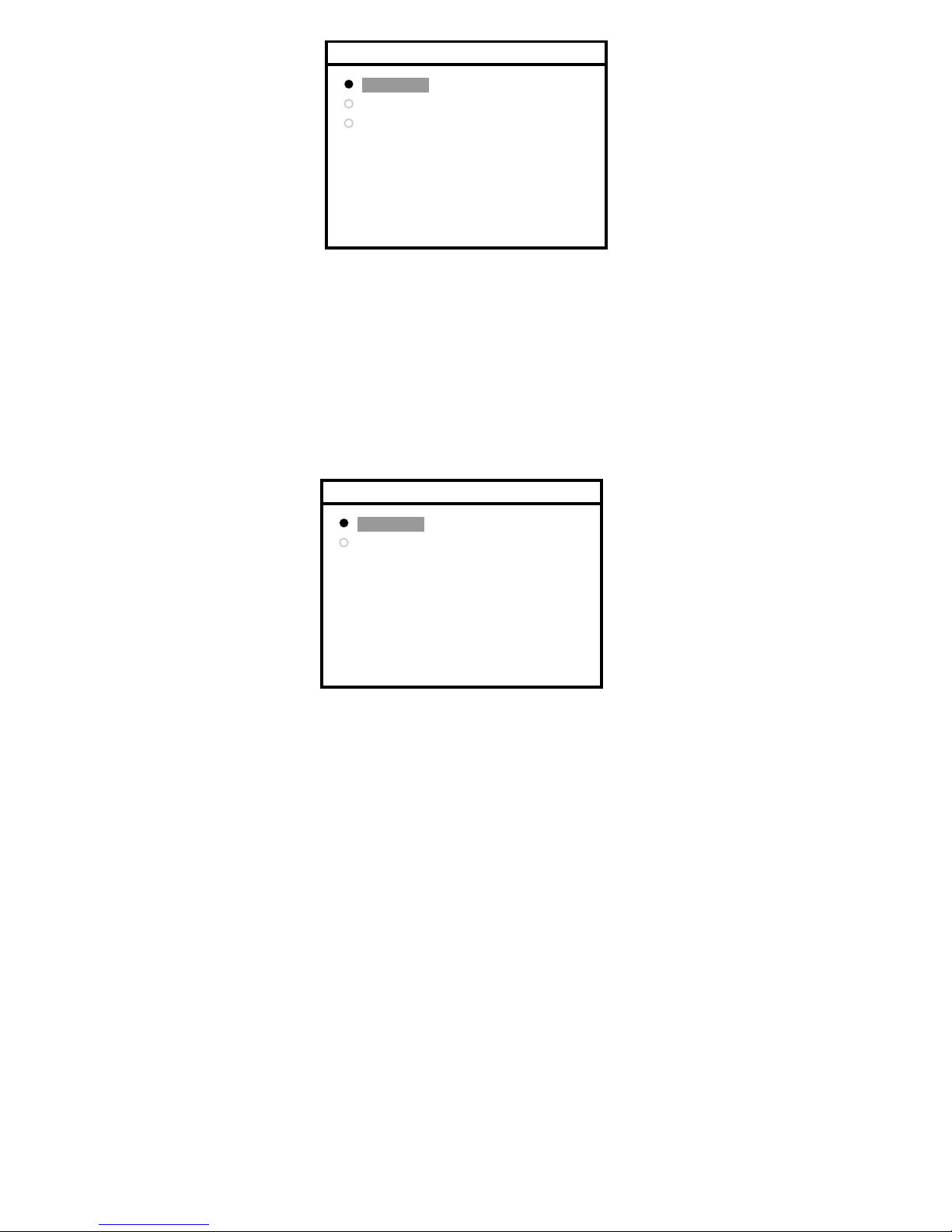
Enabled
Disabled
Auto-Clock Feature
Enabled Every time the video timing changes
Disabled Never
Enabled Every time the video timing changes
Disabled Never
Only Once Only the fi rst time that the video timing is recognized.
Enabled
Disabled
Only Once
Auto-Setup On Modest
6.3.13 Auto-Clock Feature
1) Press Enter button when the Auto-Clock Feature is highlighted on Auto-Setup Options.
The Auto-Clock Feature window appears.
2) Press Adjust + or Adjust - button until the desired item is highlighted
3) Press the Enter button to confi rm your selection and return to Auto-Setup Options window
6.3.15 Auto-(Clock/Position)
1) Press Enter button when the Auto-(Clock/Position) is highlighted on Advanced.
To perform an automatic adjustmant of the video image.
Valid only DSUB-SOG and DSUB video source.
2) Select Exit and press again Enter button to return to Image Adjust or select Auto-Level.
Page 23
23
MCL1801
6.3.17 Restore Factory Preset
1) Press Enter button when the Restore Factory Preset is highlighted on Advanced.
To reload factory settings.
2) Select Exit and press Enter button toreturn to Image Adjust.
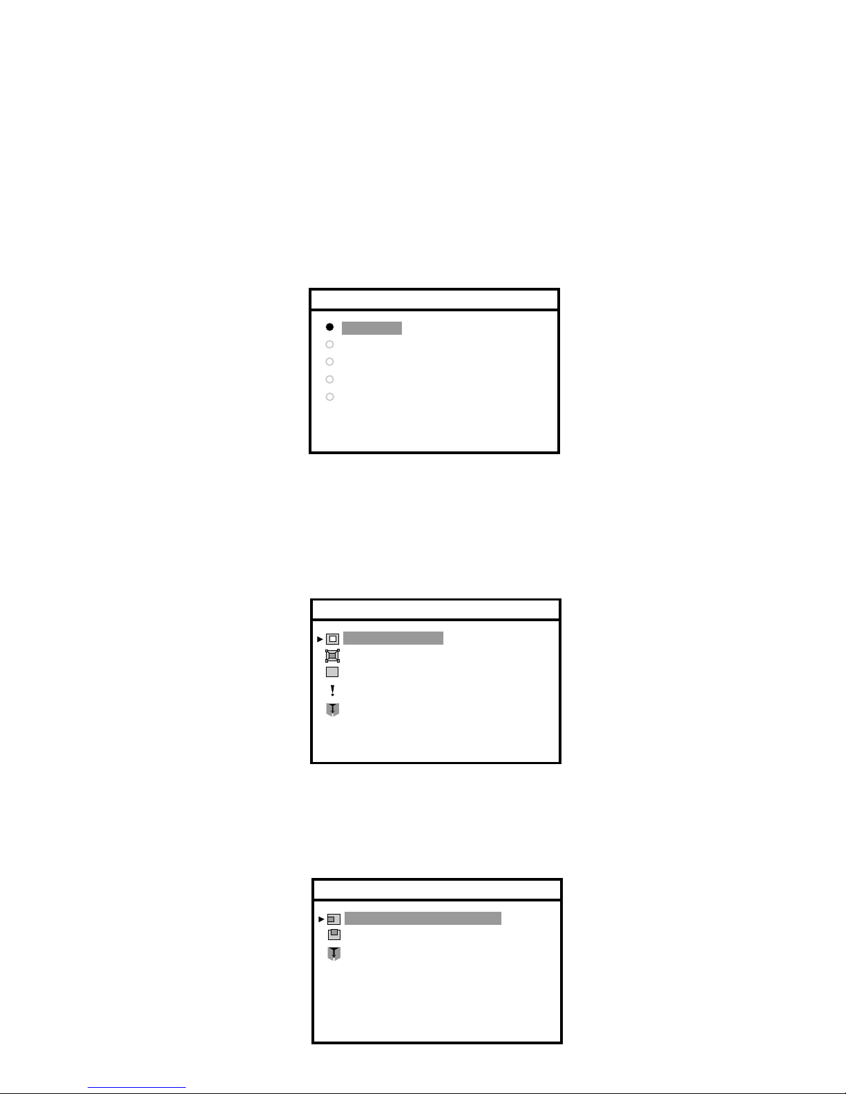
English
Français
Deustch
Español
Languages
Italiano
6.4.0 Languages
1) Press Enter button when the Languages is highlighted on Main Menu.
The Languages window appears.
The ON SCREEN DISPLAY shows the fi ve languages available.
The default is English, but you can select Français, Deustch, Español or Italiano.
2) Press the Adjust + or Adjust - button until the desired item is highlighted.
3) Press the Enter button to confi rm your selection and return to Main Menu window
6.5.0 OSD Settings
1) Press Enter button when the OSD Settings is highlighted on Main Menu.
The OSD Settings window appears.
2) Press the Menu + or Menu - button until the desired item is highlighted.
OSD Position
OSD Size
OSD Transparency
Exit
OSD Timeout
OSD Settings
Horizontal Position
Vertical position
Exit
OSD Position
6.5.1 OSD Position
1) Press Enter button when the OSD Position is highlighted on OSD Settings.
The OSD Positions window appears.
2) Press the Menu + or Menu - button until the desired item is highlighted.
Page 24
24
MCL1801
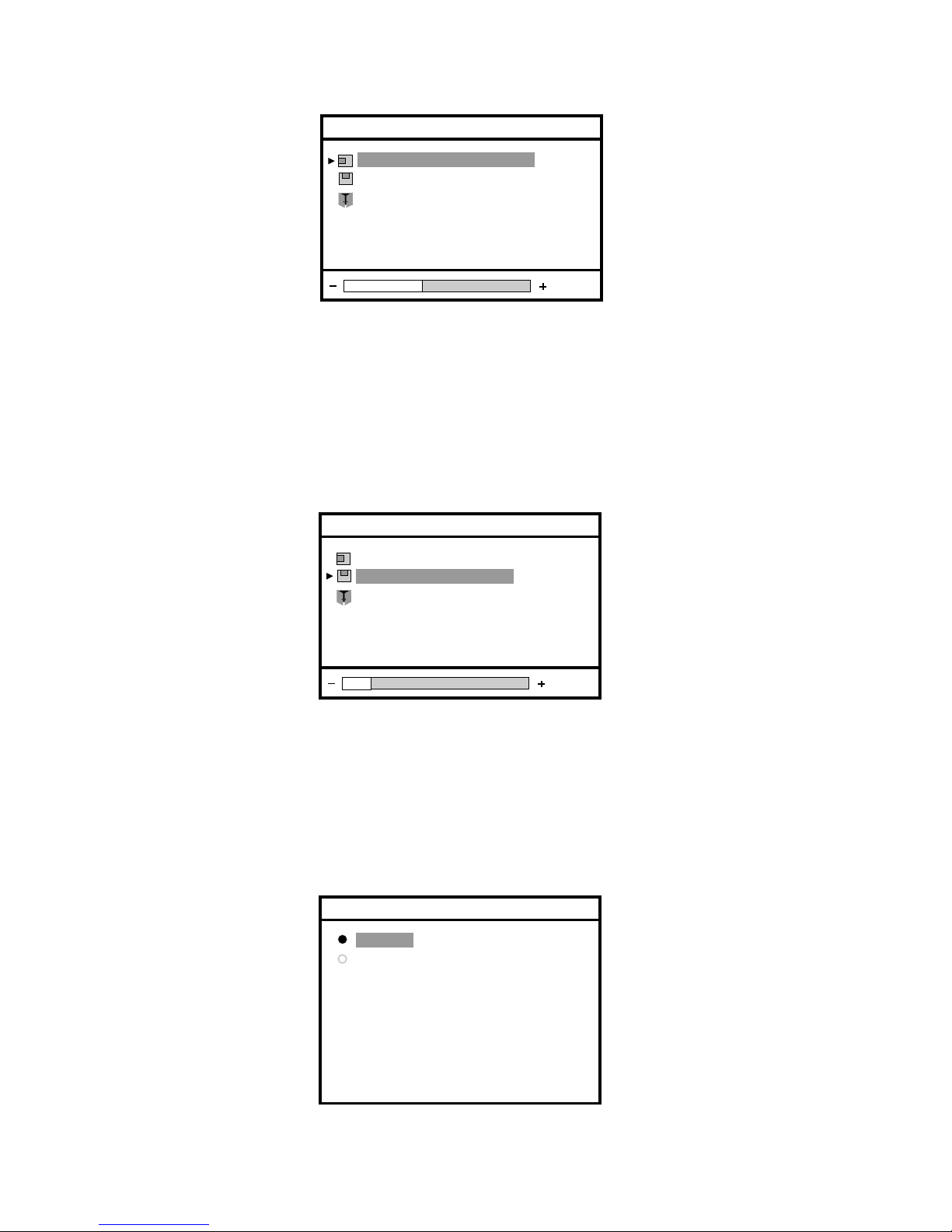
Normal
Double
OSD Size
6.5.4 OSD Size
1) Press Enter button when the OSD Size is highlighted on OSD Settings.
The OSD Size window appears.
2) Press the Adjust + or Adjust - button until the desired item is highlighted.
Normal Standard dimensions
Double Double dimension
3) Press the Enter button to confi rm your selection and return to OSD Settings window
6.5.3 OSD Vertical Position
1) Press Enter button when the Vertical Position is highlighted on OSD Position.
The Vertical Position bar appears.
Horizontal Position
Vertical position
Exit
OSD Position
2) Press Enter button and Adjust + or Adjust - button to move UP or DOWN the OSD image .
3) When the position is adjusted, press the Enter button to return to OSD Position window
4) Select Exit and press again Enter button to return to OSD Settings.
Horizontal Position
Vertical position
Exit
OSD Position
2) Press Enter button and Adjust + or Adjust - button to move the OSD image to RIGHT or to the LEFT.
3) When the position is adjusted, press the Enter button to return to OSD Position window
4) Select Exit and press again Enter button to return to OSD Settings
6.5.2 OSD Horizontal Position
1) Press Enter button when the Horizontal Position is highlighted on OSD Position.
The Horizontal Position bar appears.
Page 25
25
MCL1801
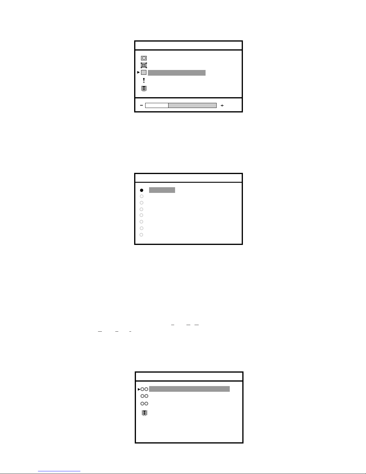
OSD Position
OSD Size
OSD Transparency
Exit
OSD Timeout
OSD Settings
10 Sec.
20 Sec.
30 Sec.
60 Sec.
45 Sec.
OSD Timeout
90 Sec.
120 Sec.
Disabled
6.5.5 OSD Transparency
1) Press Enter button when the OSD Transparency is highlighted on OSD Settings.
The OSD Transparency bar appears.
2) Press Enter button and Adjust + or Adjust - button to choose the degree of transparency of the OSD image
3) When the position is adjusted, press the Enter button to return to OSD Settings window
4) Select Exit and press again Enter button to return to OSD Main Menu.
6.5.6 OSD Timeout
1) Press Enter button when the OSD Timeout is highlight on OSD Settings.
The OSD Timeout bar appears.
2) Press Enter button and Adjust + or Adjust - button to choose the time of activation of the OSD-Menu.
3) Press the Enter button to confi rm your selection and return to OSD Settings windows.
6.6.0 Video Source
The ON SCREEN DISPLAY shows the four sources available.
The default is - DSUB
(*)
(D-sub input Video with separated syncr.).
but you can select:
- DSUB-SOG (D-sub input Video with Syncr. On Green)
- DVI (Digital Video Input)
1) Press Enter button when the Video Source is highlighted on Main menu.
The Video Source window appears.
2) Press the Adjust + or Adjust - button until the desired source is highlighted.
3) Press the Enter button to confi rm your selection and exit from OSD Main Menu.
DVI
DSUB (Ht. and Vt. Sync.)
Exit
DSUB-SOG (Green Input)
Video Source
(*) see next page
Page 26
26
MCL1801
(*) Video Source
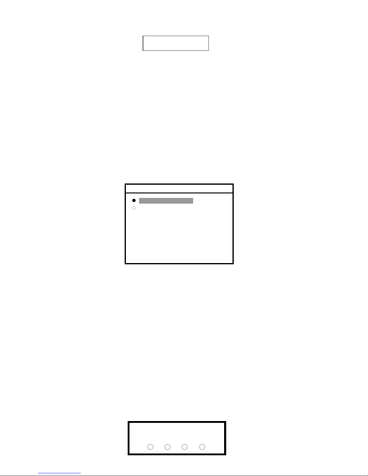
If the Video Signal is not available a warning message will appear on the screen for about 5 sec.
XXX= Current Video Source (DVI,DSUB,SOG)
After about 5 sec. the monitor will go in Stand-By mode.
The led colour will become orange.
To change the Video Source when the Video Source is not available to follow the followings steps:
- Wait the Warning Message.
- Press contemporarily the brightness keys.
- When the Warning message disappears
- Release the brightness keys.
- Execute the normal change of the Video Source. (see ref. 6.6.0)
Check Input Signal
(XXX)
6.7.0 Keyboard Option
1) Press Enter button when the Keyboard Option is highlight on Main Menu.
The Keyboard Option bar appears.
Keyboard Unlock
Keyboard Lock
Keyboard Option
2) Press the Adjust + or Adjust - button until the desired item is highlighted..
3) Press the Enter button to confi rm your selection and return to Main Menu window
REMARK:
To select the Keyboard status “LOCK or UNLOCK”, use the Keyboard Option Menu.
(The new status is stored in E2prom, the default status is UNLOCK).
If the Keyboard Status is UNLOCK any key and any OSD function is available.
If the Keyboard Status is LOCK:
- (Brightness +), . (Brightness -) and Reference Setting Recall (200 Cd/m2) are always available.
- Pressing OSD key, will appear the dialog of Fig. 26a
The OSD menu will appear after having performed the follow correct keys sequence:
○ Brightness -
○ Brightness +
○ Brightness +
○ Menu -
The dialog (Fig. 26a) will disappear any time a wrong key will be pressed.
For every right key pressed a “plus” characters appears in dialog of Fig. 26a.
KEYBOARD LOCK
Fig.26a
Page 27

INTENTIONALLY LEFT BLANK
Page 28

3119 206 1407.1
FIMI S.r.L R&D .CG0209 R2002B
 Loading...