

Page 1
Micro System
MC-55/21M
TABLE OF CONTENTS
chapter
Handling chip components and safety 1 - 1
Technical Specification & Service Tools 2 - 1
Service Measurement 2 - 2
Connections & Controls
Instructions for use
Block Diagram
Wiring Diagram 5 - 1
FRONT BOARD
circuit diagram
layout diagram
MAIN BOARD
circuit diagram
layout diagram
POWER SUPPLY BOARD
circuit diagram
layout diagram
..................................................
................................................
.................................................
........................................................
...........................................................
.......................................................
.......................................................
........................................................
........................................................
.......................................................
.......................................................
.............................
..........................
3 - 1
3 - 2 to 3 - 8
4 - 1 to 4 - 2
6 - 1
6 - 2
7 - 1
7 - 2
8 - 1
8 - 2
VCD BOARD
circuit diagram
layout diagram
REMOTE CONTROL
circuit diagram
layout diagram
EXPLODED VIEW DIAGRAM
cabinet
tape deck
Mechanical partslist
Electrical partslist
.......................................................
.......................................................
......................................................
......................................................
.................................................................
.............................................................
...............................................
...............................................
chapter
9 - 1
9 - 1
10 - 1
10 - 1
11 - 1
11 - 2
11 - 1 to 11 - 2
12 - 1 to 12 - 3
Safety regulations require that the set be restored to its original
condition and that parts which are identical with those specified
be used.
C
Copyright 1995 Philips Consumer Electroncis B.V. Eindhoven, The Netherlands
All rights reserved. No part of this publication may be reproduced, stored in a retrieval
system or transmitted, in any form or by any means, electronic, mechanical, photocopying,
or otherwise without the prior permission of Philips.
Printed in The Netherlands Copyright reserved Subject to modification
PCS 104 676
CLASS 1
LASER PRODUCT
GB
3140 785 22600Published by SS 0047 Service Audio
Page 2
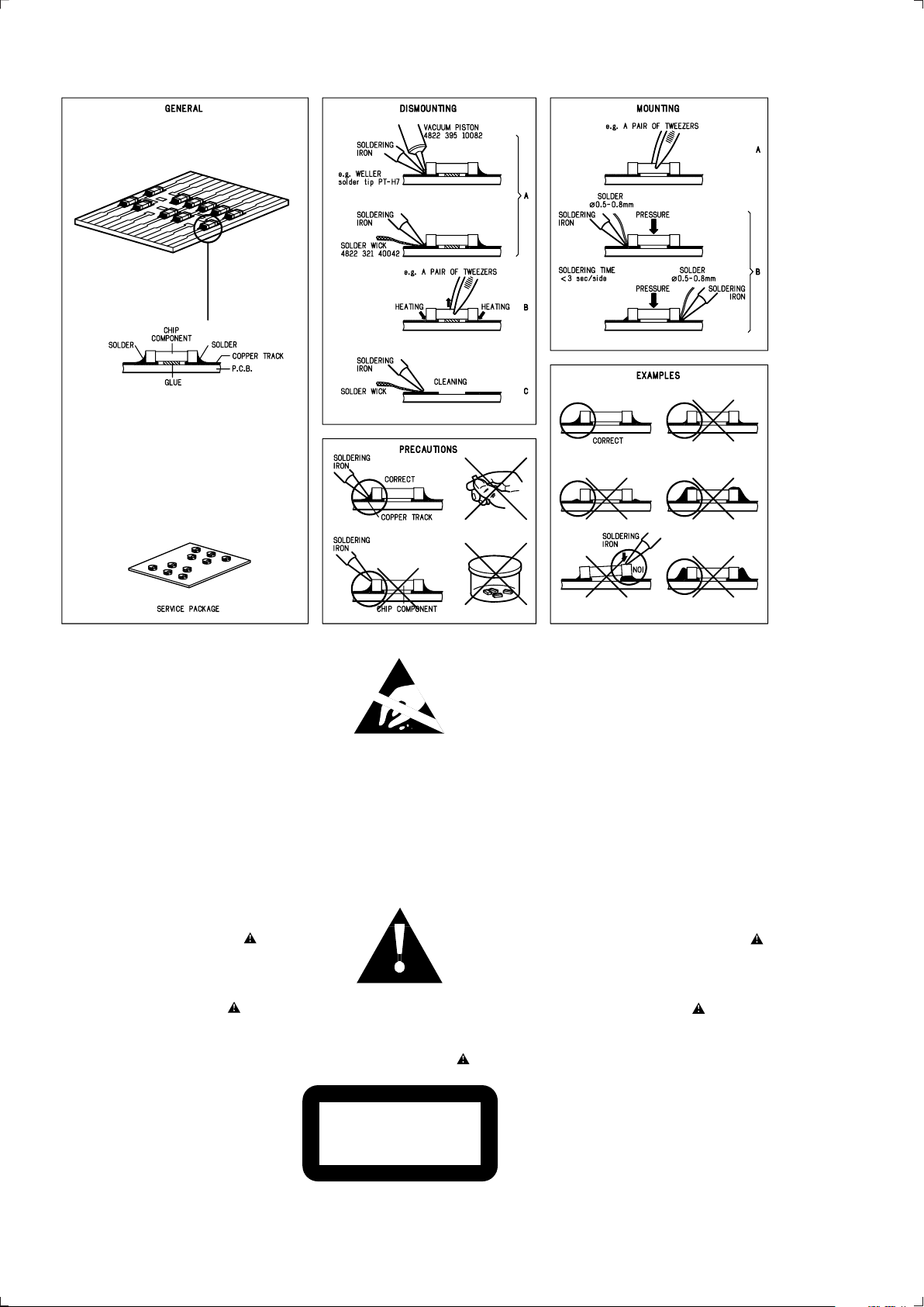
HANDLING CHIP COMPONENTS
1-1
© WARNING
All ICs and many other semiconductors are susceptible to
electrostatic discharges (ESD). Careless handling during
repair can reduce life drastically.
When repairing, make sure that you are connected with the
same potential as the mass of the set via a wristband with
resistance. Keep components and tools at this potential.
f ATTENTION
Tous les IC et beaucoup d ´autres semi-conducteurs sont
sensibles aux d écharges statiques (ESD). Leur long évite
pourrait être consid érablement écourt ée par le fait qu ´aucune
précaution n ést prise à leur manipulation.
Lors de r éparations, s ´assurer de bien être reli é au m ême
potentiel que la masse de l ´appareil et enfileer le bracelet
serti d ´une r ésistance de s écurit é.
Veiller à ce que les composants ainsi que les outils que l ´on
utilise soient également à ce potentiel.
©
Safety regulations require that the set be restored to its
original condition and that parts which are identical with
those specified be used.
Safety components are marked by the symbol
f
Les normes de s écurit é exigent que l`appareil soit remis
à l`état d`origine et que soient utilis ées les pi èces de
rechange identiques à celles sp écifiées.
Les composants de s écurit é sont marqu és
d WARNUNG
Alle ICs und viele andere Halbleiter sind empfindlich
gegen über elektrostatischen Entladungen (ESD).
Unsorgf ältige Behandlung im Reparaturfall kann die
Lebensdauer drastisch reduzieren.
Sorgen Sie daf ür, daß Sie im Reparaturfall über ein Pulsarmband mit Widerstand mit dem Massepotential des
Gerätes verbunden sind.
Halten Sie Bauteile und Hilfsmittel ebenfalls auf diesem
Potential.
d
Bei jeder Reparatur sind die geltenden Sicherheitsvorschriften zu beachten. Der Originalzustand des Ger ätes
darf nicht ver ändert werden. F ür Reparaturen sind Originalersatzteile zu verwenden.
Sicherheitsbauteile sind durch das Symbol markiert.
ESD
SAFETY
ñ WAARSCHUWING
Alle IC ´s en vele andere halfgeleiders zijn gevoelig voor
electrostatische ontladingen (ESD).
Onzorgvuldig behandelen tijdens reparatie kan de levensduur
drastisch doen vermindern. Zorg ervoor dat u tijdens reparat ie
via een polsband met weerstand verbonden bent met hetzelfde
potentiaal als de massa van het apparaat.
Houd componenten en hulpmiddelen ook op ditzelfde potentiaal .
i AVVERTIMENTO
Tutti IC e parecchi semi-conduttori sono sensibili alle scar iche
statiche (ESD).
La loro longevit à potrebbe essere fortemente ridatta in caso di
non osservazione della pi ù grande cauzione alla loro
manipolazione. Durante le riparationi occorre quindi essere
collegato allo stesso potenziale che quello della massa
delápparecchio tramite un braccialetto a resistenza.
Assicurarsi che i componenti e anche gli utensili con quali si
lavora siano anche a questo potenziale.
ñ
Veiligheidsbepalingen vereisen, dat het apparaat in zijn
oorspronkeliijke toestand wordt teruggebracht en dat
onderdelen, identiek aan de gespecificeerde, worden toegepas t.
De Veiligheidsonderdelen zijn aangeduid met het symbool
i
Le norme di sicurezza estigono che l ´apparecchio venga
rimesso nelle condizioni originali e che siano utilizzati i
pezzi di ricambiago identici a quelli specificati.
Componenty di sicurezza sono marcati con
©
DANGER : Invisible laser radiation when open.
AVOID DIRECT EXPOSURE TO BEAM.
s Varning !
Osynlig laserstr ålning n är apparaten är öppnad och
spärren är urkopplad. Betrakta ej str ålen.
∂ Advarsel !
Usynlig laserstr åling ved åbning n år sikkerhedsafbrydere
er ude af funktion. Undg å udsaettelse for str åling.
PCS 104 437
CLASS 1
LASER PRODUCT
ß Varoitus !
Avatussa laitteessa ja suojalukituksen ohitettaessa olet alt tiina
näkymättömälle laseris äteilylle. Älä katso s äteeseen !
©
After servicing and before returning the set to customer
perform a leakage current measurement test from all
exposed metal parts to earth ground, to assure no
shock hazard exists.
The leakage current must not exceed 0.5mA.
f
"Pour votre s écurite, ces documents doivent être utilis és par
des sp écialistes agr éés, seuls habilit és à réparer votre
appareil en panne".
Page 3

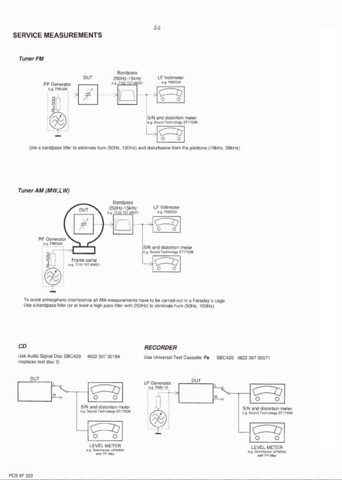
TECHNICAL SPECIFICATIONS
2-1
AMPLIFIER
Output power ....................................... 2 x 12 W RMS
........................................................................500 W PMPO
Signal-to-noise ratio .......................... ≥ 60 dBA (IEC)
Frequency response .........80 – 15000 Hz, ± 3 dB
Microphone input sensitivity ........................... 3.5 mV
Output impedance ................................................. ≥ 8 W
(1) (8 W, 1 kHz, 10% THD)
DISC PLAYER
Number of programmable tracks ......................... 20
Frequency response .......................... 20 – 20000 Hz
Signal-to-noise ratio ....................................... ≥ 60 dBA
Channel separation ............................................ ≥ 40 dB
Total harmonic distortion .................................. £ 0.6%
MPEG 1 ................................................. VCD version 2.0
MPEG 1 Layer 3 (MP3-CD) .......... MPEG AUDIO
MP3-CD bit rate ................................... 32 – 256 kbps
Sampling frequencies ...................................... 44.1 kHz
TUNER
FM wave range ...................................87.5 – 108 MHz
AM wave range .................................. 531 – 1602 kHz
Tuning grid ................................................................... 9 kHz
Number of presets (FM/AM) ........................... 20/10
Antenna
FM ....................................................................... 75 W wire
AM.............................................................. Loop antenna
4.85 kg
SPEAKERS
System ...............................2 way, double port output
Impedance........................................................................ 8 W
Woofer ................................................................... 1 x 5.25"
Tweeter...................................................................... 1 x 1.5"
Dimensions (w x h x d) .160 x 268 x 226 (mm)
Weight............................................................. 2.45 kg each
GENERAL INFORMATION
Material ..............................................................
AC Power ............................ 110 – 127 / 220 – 240 V;
....................................................... 50/60 Hz Switchable
Power Consumption
Active ......................................................................... 40 W
Standby ..................................................................£ 10 W
Dimensions (w x h x d) .. 160 x 268 x 226 (mm)
Weight (without speakers) ...............................
Subject to modification
Polystyrene
TAPE DECK
Frequency response .......... 100 – 10 kHz (±8 dB)
Signal-to-noise ratio .......................................... ≥ 44 dB
Wow and flutter ......................................... £ 0.4% DIN
SERVICE TOOLS
Audio signal disc SBC 429.......................................................................4822 397 30184
Playability test disc SBC 444
...................................................................4822 397 30245
Test disc 5 (disc without errors ) +
Test disc 5A (disc with dropout errors, black spots and fingerprints)
SBC 426/426A.....................................................................4822 397 30096
Burn in test disc (65 min. 1kHz signal at -30 dB level without “pause”)
.....4822 397 30155
Universal test cassette Fe SBC 420........................................................4822 397 30071
AVAILABLE ESD PROTECTION EQUIPMENT
anti-static table mat large 1200x650x1.25mm 4822 466 10953
small 600x650x1.25mm 4822 466 10958
anti-static wristband 4822 395 10223
connection box (3 press stud connections, 1MΩ) 4822 320 11307
extendible cable (2m, 2MΩ, to connect wristband to connection box) 4822 320 11305
connecting cable (3m, 2MΩ, to connect table mat to connection box) 4822 320 11306
earth cable (1MΩ, to connect any product to mat or to connection box) 4822 320 11308
KIT ESD3 (combining all 6 prior products - small table mat) 4822 310 10671
wristband tester 4822 344 13999
PCS 104 677
Page 4
Page 5
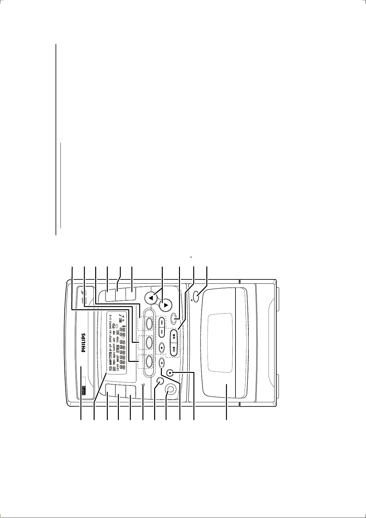
CONNECTIONS AND CONTROLS
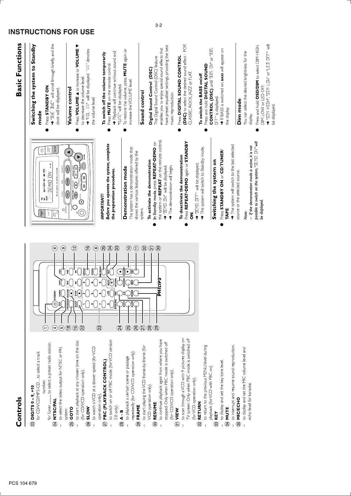
Controls
frequency or to search radio
for Tuner .............. to tune to a lower or higher radio
stations.
for Tape ...............to rewind or fast forward.
for Clock ............ to set the hour and minutes.
for Timer .............to set the timer function.
PRESET 4 3
PLAY•PAUSE 2Å
DIRECTIONÅ1 2Å
for CD/VCD/MP3-CD…to start or interrupt
playback (only 2Å is available).
for Tuner .............to select a preset radio station.
for Tape ...............to start playback in selected
direction or pause.
# # OPEN
– to open the tape deck door.
$ Tape compartment
% RECORD 
only).
– to start recording (in CD/VCD or Tuner mode
^ REPEAT•DEMO
for MP3-CD only…to repeat a track, an album
3-1
or whole disc.
whole disc.
for CD/VCD ....to repeat a disc track or the
for DEMO .........to activate/deactivate the
demonstration.
& MIC
– to connect microphone.
* PROGRAM
tracks.
for CD/VCD/MP3-CD…to programme disc
for Tuner .............to programme preset radio
stations.
for Clock ............ to set or reset clock.
for Timer .............to set or reset timer.
for System ......... to erase EEPROM.
( iR SENSOR
– infrared sensor for remote control.
) TIMER ON/OFF / SET
– to activate/deactivate or set the timer.
¡ CLOCK
– to view the clock or set the clock
– to select the sleep time.
(à á)
T
S
™ SLEEP
– to select the sleep time.
Controls on the system and
remote control
STANDBY ON B
– to switch the system on or to Standby mode.
2 DISPLAY SCREEN
– to view the current status of the system.
3 Disc tray
4 VCD / SHUFFLE
– to select CD/VCD mode (this system can
7
6
OPEN/
CLOSE
1
4
1
5
playback MP3-CD format disc). When in CD/
VCD mode, press to start or stop shuffle play
8
OSD/DIM
STEREO/
VOCAL
3
2
mode.
press to select the waveband: FM or MW.
5 TUNER / BAND
– to select Tuner mode. When in tuner mode,
9
BAND
TUNER TAPE
55 VIDEO CD MICRO SY STEM
-
VCD
MC
SHUFFLE REV.MODE
6 TAPE / REV. MODE
– to select Tape mode. When in tape mode, press
0
4 PRESET 3
REPEAT•DEMO STOP •CLEAR SEARCH•TUNING
to select AUTO REVERSE.
7 OPEN/CLOSE
– to open or close the disc tray.
8 STEREO/VOCAL
!
VOLUME
CONTROL
DIGITAL SOUND
DIRECTION PLAY•PAUSE
RECORD
mode (on FM band only).
for Tuner .............to switch between stereo/mono
for CD/VCD ....to set vocal mode.
9 OSD/DIM
– to switch on/off the on screen display on the TV
#
@
OPEN
DIGIT AL SOUND CONTROL
screen.
– to select DIM HIGH, DIM LOW or LED OFF.
0 VOLUME 3 4
– to increase or decrease the volume.
– to increase or decrease the microphone volume
AUTO REVERSE
level, echo level or key tone level.
! DIGITAL SOUND CONTROL (DSC)
CLASSIC, ROCK, JAZZ or FLAT.
– to select the desired sound effect : POP,
STOP• CLEAR 9
for CD/VCD/MP3-CD…to stop playback or to
– to switch on/off BASS mode.
@ Mode Selection
clear a programme.
for Tuner .............to stop programming.
album or track.
for Tape ...............to stop playback or recording.
SEARCH• TUNING
for MP3-CD only…to select previous/next
for CD/VCD ....to search backward/forward or
to skip to the previous/next track
during playback.
MP3-CD
PLAYBACK
3
2
ON
STANDBY
1
CLOCK
¡
TIMER
SET
ON/OFF
)
iR SENSOR
(
PROGRAM
*
MIC
&
^
%
$
PCS 104 678
Page 6
Page 7
INSTRUCTIONS FOR USE
3-3
repeatedly to select another
T
To select and playback another track
during playback mode
or
S
CD / VCD / MP3-CD
1 Press
Playing a normal disc
1 Press 2Å to star t playback.
track.
‹ The current track continues playing.
‹ The new selected track will show on the
display screen and TV screen.
‹ The track number and elapsed playing time of
the current track appear on the display.
‹ The playing time will start flashing.
l To interrupt playback, press 2Å.
track.
2 Press ÉÅ to start playback the new selected
l To resume playback, press 2Å again.
2 To stop playback, press 9.
Note:
Selecting a desired track/passage
– "A" represents ALBUM and "T" represents
TITLE, "XX" or "XXX" is the current selected
o select a desired track
T
Album or Track number.
repeatedly (or digits 0 – 9,
T
or
S
l Press
s on the display.
+10 on the remote control) until the desired
track appear
Programming tracks
Programming tracks of disc is possible when
playback.
l If playback is stopped, press ÉÅ to start
playback is stopped. Up to 20 tracks can be
stored in the memory in any order (except for
MP-3 CD).
programme setting.
‹ PROG and the current selected track number
1 In stop mode, press PROGRAM to enter
and release it when
T
or
S
the desired passage is located.
To search for a particular passage during
‹ During searching, the volume will be reduced.
playback
l Press and hold
will start flashing.
‹ “PXX TXX” will show on the display screen
and TV screen.
2 Press digits 0 – 9, +10 on the remote control
until the desired
T
or
S
For MP3-CD only
To select a desired Album
l Press and hold
to select the desired track.
T
/
S
or
Album number appear on the display.
3 Press PROGRAM to store the select track.
‹ “AXX T001” will be displayed and the album
and TV screen.
‹ “PXX OK” will show on the display screen
name will scroll through the display briefly.
in stop mode to review the
T
or
S
PROG will remain on the display.
‹ The total tracks number and elapsed playing
times will appear on the display.
‹
l Repeat steps 1 to 3 to store other tracks.
4 Press 9 to end programme setting.
l Press
repeatedly to select a desired
T
or
S
track from the current Album.
To select a desired Track
‹ “A01 TXXX” will be displayed and the track
‹ On TV screen, the arrow will move forward/
backward in the ALBUM menu.
l Press
playback, the current track or all programmed
l If you press REPEAT during programme
backward in the TRACK menu.
REPEAT 1/REPEAT ALL and PROG will appear
tracks will be played repeatedly.
‹
select the track under current Album directly.
on the display.
‹ “PRG CLEAR” will be displayed.
‹ PROG will disappear from the display.
6 Press 9 in stop mode to clear the programme.
programme sequence.
name will scroll through the display briefly.
5 Press 2Å to play the programmed tracks.
‹ On TV screen, the arrow will move forward/
l Use the digital keys on the remote control to
Support following MP3-CD formats:
l ISO 9660 format - Max. 17 characters
l Max. Track number plus Album is 256
MP3-CD
PLAYBACK
CD / VCD / MP3-CD
nested directory is 8 levels
l Max.
l The max. ALB number is 99
l The max. MP3 programme track number is 99
l The max. length of each track is 255 minutes 59
OPEN/
CLOSE
1
ON
STANDBY
seconds
STEREO/
VOCAL
3
2
CLOCK
TIMER
l The player can play mixed mode disc:
OSD/DIM
55 VIDEO CD MICR O SYSTEM
-
MC
SET
ON/OFF
a: MP3 + CDDA can only play the MP3
BAND
SHUFFLE REV.MODE
tracks in the first block.
b: VCD + CDDA full support
44.1 kHz
128, 192, 256 (kbps)
Following formats can’t be supported
l Supported VBR bit-rate
l Supported sampling frequencies for MP3 disc :
l Supported Bit-rates of MP3 disc are: 32, 64, 96,
VOLUME
CONTROL
DIGITAL SOUND
TUNER TAPE
4 PRESET 3
DIRECTION PLAY•PAUSE
VCD
RECORD
REPEAT•DEMO STOP•CLEAR SEARCH•TUNING
PROGRAM
iR SENSOR
MIC
IMPORTANT!
– This system is designed for regular discs.
Loading a disc
l The files like *.WMA, *AAC, *.DLF, *.M3U, *.PLS
l Chinese filename
l The non-session closed discs
l The discs recorded under UDF format
Therefore, do not use any accessories such
as disc stabilizer rings or disc treatment
sheets, etc., as offered on the market,
because they may jam the disc mechanism.
– Do not load more than one disc into the
tray.
– When the tray is loaded with disc, do not
‹ The disc tray slides out.
‹ The total number of tracks and the playing
time of the disc appear on the display.
For MP3-CD only
the set is switched to corresponding PAL or
NTSC system of your TV set (exception
l Load a MP-3 CD format music disc on the CD
Multi-system TV).
1 Press VCD to select CD/VCD mode.
2 Press OPEN•CLOSE.
3 Load a disc with the label side facing up.
4 Press OPEN•CLOSE to close the disc tray.
shake the system, this may jam the tray.The CD part of this system also serves as a
Video CD player if you connect it to your
TV set.
Before viewing the Video CD, ensure that
tray.
Discs for Playback
‹ The total album number and total track
This system can playback all digital audio CD,
number will scroll through the display briefly,
‹ On TV screen, the total ALBUM and TRACK
then "A01 T001" will be displayed
video CD, finalised digital audio CD-Recordable
(CDR) discs and finalised digital audio CD-
number will display, also with the album list (max.
5 lines per page) and an arrow. The arrow
indicates the current selected music.
Rewritable (CDRW)discs.
Notes:
– To ensure good system performance, wait until
the disc tray completely reads the disc before
proceeding.
– For MP3-CD, the disc reading time may exceed
10 seconds due to the large number of songs
compiled into one disc.
PCS 104 680
Page 8

INSTRUCTIONS FOR USE
2
VCD / MP3-CD
3-4
CD /
If the menu consists of a list of titles, you
can select a sequence directly
to select your choice.
‹ The VCD starts playing of the selected
1 Press digits 0 – 9, +10 on the remote control
ÉÅ
ÅÑ
VCD TUNER TAPE OSD
PROGRAM RECORD
VIDED CD
to go through the pages.
T
/
back to the previous menu.Note:
– If a menu consists of more than one page, press
sequence automatically.
S
2 Press RETURN on the remote control to go
á
à
SLEEP STOP
REPEAT
ÇHâ
12 3
VOCAL
45 6
MIC/ECHO
78 9
KEY
MUTE
0 +10
Switching off PBC
‹ On TV screen, “PBC OFF” will be displayed.
Notes:
– Programme mode is not available whenever PBC
mode is switched on.
l In stop mode, press PBC.
É
É
VOLUME
GOTO A-B RESUME
SLOW FRAME VIEW DSC
NTSC/PAL PBC RETURN
– The menu structure depends on the programme
stored on the VCD. Please refer to the information
supplied with the disc.
Adjusting the TV System
Before viewing the Video CD, ensure that the set
is switched to corresponding PAL or NTSC
system of your TV set (exception Multi – system
on the TV screen.
‹ The sound will be muted.
Pause
TV).
‹ On TV screen, “PAUSE” will be displayed.
1 During playback, press 2Å to have a still picture
switch between NTSC and PAL TV system.
‹ After TV system is selected, the set will
automatically switch to the last TV system setting
2 Press 2Å again to continue playback.
l Press NTSC/PAL on the remote control to
Goto
‹ “GO XX:XX” will be displayed.
‹ On TV screen, “GOTO XX:XX” will be
displayed.
1 Press GOTO on the remote control.
every time the VCD source is selected.
OSD – On Screen Display
If you insert VCD/CD, your TV screen will ser ve
as an additional display for messages (e.g. PLAY,
STOP), and information stored on the VCD/CD.
to key in the disc time which you want the disc
to begin playback.
Note:
– The disc time entered should not be greater
than the total disc time.
2 Press digits 0 – 9, +10 on the remote control
DIM on the system repeatedly to select viewing
various information.
‹ The current track and current /remaining
time in the track/disc appear on the display.
l Press OSD on the remote control or OSD/
Playing a Video CD with PBC
VCD with PBC (Playback Control) will be
indicated on the display of the set and on your
TV screen as soon as they are inserted. PBC is a
predefined play sequence stored on the VCD.
1 Switch on the TV, insert a VCD with PBC.
2 Menu appears on the TV screen.
Shuffle
You can play all the tracks/programmed tracks in
random order.
XX" is the current selected
VCD / MP3-CD
epresents TRACK, "
r
Notes:
– "P" represents PROGRAMME and "T"
CD /
SHUFFLE (VCD) to enable SHUFFLE play
mode.
‹ SHUFFLE will appear on the display.
1 During playing, pause or stop mode, press
leared as
Programme or Track number.
– The programming is automatically c
soon as the CD compartment is opened.
– The function of programme setting is disable in
again or 9.
‹ SHUFFLE will disappear from the display.
2 To exit shuffle mode, press SHUFFLE (VCD)
PLAY/PAUSE mode.
– Programme cannot be used for VCDs when PBC
is switched on. Switch off PBC before storing tracks
from such a VCD.
Note:
– If the Shuffle function enabled, and the Repeat
function is set on, will disable the Shuffle play
mode.
Repeat
You can play the current track or the whole disc
repeatedly.
REPEAT on the remote control or REPEAT/
DEMO on the system to select REPEAT 1 or
REPEAT ALL mode.
1 During CD Playing or Pause mode, press
repeatedly (or
to select the desired
T
/
T
/
S
S
For MP3-CD only
‹ On TV screen, “PXX A XX TXX?” and
1 In stop mode, press PROGRAM.
“PROGRAM” will be displayed.
‹ PROG and “AXX TXXX” will star t flashing.
ALBUM and press
2 Press and hold
‹ “PXX OK” will appear on the display briefly
select the desired TRACK for programming.
and the programmed album and track number
digits 0 – 9, +10 on the remote control) to
3 Press PROGRAM to store the selection.
‹ REPEAT 1 – to repeat the current track.
will be displayed.
– to repeat the whole disc.
ALL
REPEAT
‹
REPEAT ALL or REPEAT ALB mode.
‹ REPEAT ALB – to repeat the current album.
played repeatedly until you press 9.
l For MP3-CD, you are able to select REPEAT 1,
l The current track or whole disc will now be
in stop mode can review the
T
or
S
‹ PROG will remain on the display.
album and track.
l Repeat steps 1 to 3 to store other desired
l Press
programme sequence.
‹ “PXX AXX TXXX” will scroll through briefly.
the REPEAT 1/REPEAT ALL/REPEAT ALB disappears
from the display.
Notes:
– If the Repeat function is enable, and the Shuffle
function is set on, will disable all the Repeat play
modes.
– If the Repeat function is enable, and the Stop
2 To exit the repeat mode, press REPEAT until
to select the programmed track
T
/
S
programme information.
‹ The Album’s name and Track’s name will scroll
through briefly.
press
to play.
l Press OSD in stop mode to show the
4 Press 2Å to start programme playback. You can
5 Press 9 once stop programme playback or
button is pressed, will disable all the Repeat play
modes.
– In programme mode, you can only select Repeat
1 or Repeat All function.
twice to clear the programme.
PCS 104 681
Page 9

INSTRUCTIONS FOR USE
CD / VCD / MP3-CD
3-5
MIC Volume and Echo
This feature allows you to add echo while singing
or talking through a microphone.
To adjust microphone volume level
repeatedly until “MIC 6” is displayed.
1 Press MIC/ECHO on the remote control
2 Press VOLUME 3 or 4 to increase or
Resume
control to start playback again from where you
have stopped.
Note:
– Resume will not be available if you have
changed the disc, opened the disc tray or
l In stop mode, press RESUME on the remote
“MONO LEFT” ™ “ MONO RIGHT” ™
“VP LEFT” ™ “ VP RIGHT” ™ “ STEREO” ...
STEREO – same effect as the original recorded
disc.
VOCAL LEFT/RIGHT – fade out the original
vocal for special recorded Karaoke disc only
(with the ECHO mode switched on).
MONO LEFT/RIGHT – select the language on a
decrease the MIC volume.
‹ The volume level will be displayed.
To adjust echo level
disconnected the system the power supply.
View
This feature allows you to scan through a VCD for
decrease the echo level.
‹ The echo level will be displayed.
repeatedly until “ECHO 6” is displayed.
1 Press MIC/ECHO on the remote control
2 Press VOLUME 3 or 4 to increase or
.
T
or
S
a quick review. PBC mode must be switched off.
Press VIEW on the remote control.
‹ On TV screen, 9 pictures will be displayed. To
view the previous/next page, press
1
To Play a certain scene or
Vocal
This feature allows you to fade out the original
vocal from a Karaoke VCD. You can also use it to
select the different audio modes.
STEREO/VOCAL on the system repeatedly
to select the following modes:
l Press VOCAL on the remote control or
‹ The first 20 seconds of each track will be
played.
playback the desired track or 2Å to play the
current selected track.
Return
return to the previous VCD disc MENU level. It
is functional only for Video CD when PBC is
switched on.
Key ( I È i )
This feature allows you to change the key tone
2 To exit review mode, press digits 0 – 9, +10 to
ing
l Press RETURN on the remote control to
bilingual VCD.
“0”.
of your vocal range.
‹ The last selected key tone level will be
displayed.
1 Press KEY on the remote control.
l Press KEY again to change the tone level to
‹ The key tone level can be increase or
decrease between level +8 and -8.
2 Press VOLUME 3 or 4 to adjust the key tone.
Slow
CD / VCD / MP3-CD
1 Press SLOW on the remote control to watch a
VCD at a slower speed. There are 3 types of
slow modes to select.
‹ The sound will be muted.
‹ On TV screen, “SLOW 1/2”, “SLOW 1/4” or
“SLOW 1/8” will be displayed.
2 To resume playback at normal speed, press
” will appear on the display.
=
SLOW repeatedly until “SLOW X/X”
disappears from the TV screen or press 2Å.
A-B repeat
This feature is also applicable to audio CD
(except for MP3-CD).
passage of the disc repeatedly.
playback to mark the start point of the chosen
scene or passage.
‹ “A
1 Press A-B on the remote control dur
B” will appear on the display.
=
‹ “B” will start flashing.
scene or passage.
‹ “A
‹ The selected scene or passage will start
playing repeatedly.
2 Press A-B again to mark the end of the chosen
3 Press A-B once more to return to normal
B” will disappear from the display.
playback.
‹ “A
Notes:
– You can also cancel A-B repeat by pressing Sor
.
T
– A-B repeat marking can cross from one track to
another. But for VCD 2.0, you can only able to set
the A-B repeat marking within the same track.
Frame
repeatedly to get the still picture and frame-by-
frame playback.
‹ The player will go into pause mode
1 Press FRAME on the remote control
2 To resume normal playback, press 2Å.
=
PCS 104 682
Page 10

INSTRUCTIONS FOR USE
to rewind or fast forward the
T
or
S
ape Operation/Recording
T
Rewind/Fast forward
tape.
‹ "TAPE" with the direction indicator will
1 Press
OSD/DIM
STEREO/
VOCAL
OPEN/
CLOSE
3
1
2
-
the rewinding or fast forwarding.
appear on the display.
55 VIDEO CD MICR O SYSTEM
MC
SHUFFLE REV.MODEBAND
2 Press Ç to stop rewinding or fast forwarding.
l The tape will stop automatically at the end of
TUNER TAPE
VCD
REPEAT•DEMO STOP•CLEAR SEARCH•TUNING
General information on
VOLUME
CONTROL
DIGITAL SOUND
4 PRESET 3
DIRECTION PLAY•PAUSE
RECORD
recording
l Recording is permissible if copyright or other
OPEN
DIGIT AL SOUND CONTROL
void
ou do not intend to record via the
rights of third parties are not infringed upon.
microphone, unplug the microphone to a
l If y
3-6
accidental mixing with other recording source.
(normal tape).
regardless of the position of the Volume, DSC
and so forth.
l For recording, use only tape of IEC type I
l The recording level is set automatically,
l The tape is secured at both ends with leader
∂ ∂
∂ ∂
∂ for recording on both sides.
tape. At the beginning and end of the tape,
nothing will be recorded for six to seven
seconds.
tab on the left shoulder of the tape side you
want to protect.
the protection tab has been broken. Put a piece
of clear adhesive tape over the opening.
Recording
l To prevent accidental recording, break out the
l If “ERROR” or “TAPE PROTECTED” is displayed,
select a recording mode.
1 Load a recordable tape into the tape deck.
2 Press REV. MODE (TAPE) repeatedly to
source.
‹ å for recording on one side only.
‹
3 Press VCD or TUNER to select the recording
4 Press RECORD.
‹ “REC < >” will be displayed and REC starts
flashing.
direction for recording.
‹ REC will remain on the display.
‹ The selected recording source will continue
5 Press Å1 or 2Å to start and select the
l To stop recording, press Ç.
playing.
Tuner
6 Press PROGRAM again to store the radio
ON
STANDBY
station.
‹ “STORED” will be displayed.
OPEN/
CLOSE
1
ON
STANDBY
3
2
CLOCK
l Repeat steps 3 to 6 to store other preset radio
STEREO/
CLOCK
VOCAL
iR SENSOR
SET
TIMER
ON/OFF
stations.
Note:
– During programming, if no button is pressed
OSD/DIM
BAND
TUNER TAPE
55 VIDEO CD MICR O SYSTEM
-
MC
VCD
SHUFFLE REV.MODE
iR SENSOR
SET
TIMER
ON/OFF
PROGRAM
within 5 seconds, the system will exit programme
REPEAT•DEMO STOP•CLEAR SEARCH•TUNING
PROGRAM
MIC
mode automatically.
MIC
Tuning to preset radio stations
number.
l Press Å1 or 2Å to select the desired preset
VOLUME
CONTROL
DIGITAL SOUND
4 PRESET 3
DIRECTION PLAY•PAUSE
RECORD
Loading a tape
the tape deck door.
and close the tape door.
open side down.
1 Press # OPEN to open
2 Insert a recorded tape
l Load the tape with the
, radio frequency, and
‹ The preset number
waveband will appear on the display.
Mono/Stereo
mono or stereo mode.
‹ When STEREO mode is selected, STEREO will
appear on the display.
Note:
l Press STEREO/VOCAL repeatedly to select
until "SEARCH" is
T
or
S
Tuning to radio stations
‹ “TUNER” will be displayed and then followed
by the current radio frequency.
waveband : FM or AM.
displayed.
‹ "SEARCH" will start flashing until a radio
station with sufficient signal strength is found.
1 Press TUNER to select Tuner mode.
2 Press BAND (TUNER) to select the desired
3 Press and hold
Tape playback
– You are able to select mono or stereo mode in
FM band only.
reached.
l Repeat this procedure until the desired station is
playback.
‹ "PLAY" with playback direction indicator will
appear on the display.
1 Press TAPE to select Tape mode.
2 Press Å1 or 2Å to select the direction for
or
S
repeatedly until the display shows the
T
desired frequency or when the best reception
has been obtained.
l To tune to a weak station, briefly press
or 2Å button.
‹ "PAUSE" will be displayed.
l To interrupt playback, press the last selected Å1
l To resume playback, press Å1 or 2Å again.
3 To stop playback, press 9.
Storing preset stations
You can store up to 20 for FM and 10 for AM
radio stations in the memory. When a preset
radio station is selected, the preset number
appears on the display.
Auto Reverse
select the different playback modes.
å : playback on one side of the tape only.
l Press REV. MODE (TAPE) repeatedly to
Manual programming
waveband: FM or AM.
1 Press TUNER.
2 Press BAND (TUNER) to select the desired
to 10 times each side unless you pressÇ.
∂ : both sides are played once.
∫ : both sides are played repeatedly, up
to tune to the desired
T
or
S
frequency.
‹ PROG will start flashing.
‹ The current preset number will be displayed
for selection.
3 Press
4 Press PROGRAM.
5 If you wish to store the radio station to another
preset number, press Å1 or 2Å to select the
desired preset number.
PCS 104 683
Page 11

INSTRUCTIONS FOR USE
Clock/Timer
Timer setting
The system can switch on to VCD, TUNER or
TAPE mode automatically at a preset time,
serving as an alarm to wake you up.
IMPORTANT!
– Before setting the timer, ensure that the
clock is set correctly.
– The timer will not start at the preset
time if the system is switched on in one of
the source mode (VCD, TUNER, for
example).
OSD/DIM
STEREO/
VOCAL
OPEN/
CLOSE
TUNER TAPE
VCD
REPEAT•DEMO STOP•CLEAR SEARCH•TUNING
PROGRAM
VOLUME
CONTROL
DIGITAL SOUND
4 PRESET 3
DIRECTION PLAY•PAUSE
RECORD
MIC
3
1
2
BAND
55 VIDEO CD MICR O SYSTEM
-
MC
SHUFFLE REV.MODE
iR SENSOR
SET
ON
CLOCK
STANDBY
TIMER
ON/OFF
– The timer can only be activated from
y mode.
Standb
View clock
1 Press and hold TIMER ON/OFF (SET) for
The clock (if it is set) will be shown in Standby
repeatedly to view the
T
or
S
more than 2 seconds to select timer setting
mode.
‹ TIMER will appear on the display.
l Press
mode.
To view the clock in any source mode
(VCD or TUNER for example)
3-7
to select the desired source.
T
or
S
previous setting.
setting or start a new setting.
‹ "TUNER", "TAPE", "CD" or "REC TU" will start
flashing.
2 Press PROGRAM to change the previous
ed for a few seconds.
‹ The clock will be display
‹ If the clock has not been set, "24 HOUR" or
l Press CLOCK.
"12 HOUR" will start flashing.
3 Press
Clock setting
to select a desired preset
T
or
S
TUNER to select the current radio station or
press
4 Press PROGRAM to confirm the selection.
l If "TUNER" or "REC TU" is selected, press
The clock can be set in either 12- or 24-hour
mode, for example "AM 12:00" or "00:00".
1 Press CLOCK to select clock mode.
2 Press PROGRAM to select clock setting mode.
to set the volume level.
T
or
S
radio station.
‹ "VOL" and the volume level will start flashing.
5 Press
to select 12- and 24- hour
T
or
S
‹ "24 HOUR" or "12 HOUR" will start flashing.
mode.
3 Press
‹ ON and the hour indication will start flashing.
6 Press PROGRAM to confirm the setting.
‹ The hour indication will start flashing.
4 Press PROGRAM to confirm the selection.
to set timer start hours and
T
or
S
Press
7 Set the time to start playback.
to set the hours.
T
or
S
5 Press
6 Press PROGRAM to confirm the selection.
press PROGRAM to store the setting and
repeat the same procedure to set the minutes.
‹ OFF and the hour indication will start flashing.
above procedure.
‹ "TIMER OK" will be display briefly and the
timer is now set.
8 Set the time to stop playback following the
source will play if the timer has been activated.
9 Switch the system to standby mode.
l When reached the preset timer, the selected
to set the minutes.
T
or
S
‹ The minutes indication will start flashing.
‹ The clock will start working.
the system.
Notes:
– The clock setting will be erased when the power
cord is disconnected or if a power failure occurred.
– During clock setting, if no button is pressed
within 5 seconds, the system will exit clock setting
mode automatically.
7 Press
8 Press PROGRAM to store the setting
l To exit without storing the setting, press Ç on
ape Operation/Recording
T
Note:
Notes:
– Keep the microphone away from the speakers to
prevent howling.
– Microphone mixing only available in CD/VCD
mode.
5 Start singing or talking through the microphone.
MIC
Microphone Mixing
Connect a microphone (not supplied) to the
system allowing you to sing along with the music
– During recording, it is not possible to change
tape direction or listen to another source.
Recording timer
To record a radio station from a specified time,
you will need to use a preset radio station and
to set a start (ON) and finish (OFF) time.1Load a recordable tape into the tape deck.
‹ If desired, select tape reverse mode option.
Follow the “TIMER SETTING” procedure as
described on page 21 to store the starting and
finishing time for recording. Select “REC TU” a s
the wake up source for timer recording.
Note:
– If the system is switched on at the preset time,
the recording will not be made.
2
Karaoke
source.
ECHO to set the microphone volume to the
minimum level to prevent howling sound (refer
to “MIC Volume and Echo” page 17).
VOLUME control.
1 Connect a microphone to the MIC jack.
l Before connecting the microphone, press MIC/
2 Select VCD and press 2Å to start playback.
3 Adjust the volume level of the source with
4 Press MIC/ECHO to adjust the MIC and
PCS 104 684
ECHO level to the desired mixing level.
Page 12

INSTRUCTIONS FOR USE
oubleshooting
Tr
has cleared.
MP3-CD.
– Check if the disc is inser ted upside down.
– Wait until the moisture condensation at the lens
– Replace or clean the disc, see “Maintenance”.
– Use a readable disc or correct recorded format
NTSC setting.
connect an external antenna for better reception.
and your TV or VCR.
– Increase the distance between the Micro System
TION/RECORDING
– Use only NORMAL (IEC I) tape.
tab space.
– Apply a piece of adhesive tape over the missing
3-8
switch on the system again.
– Check if the stripped speaker wire is clamped.
32-256 kbps bit rate with sampling frequencies at
48 kHz, 44.1 kHz or 32 kHz.
– Make sure the MP3-CD was recorded within
– Reduce the distance between the remote control
and the system.
(+/– signs) aligned as indicated.
– Inser t the batteries with their polarities
– Replace the batteries.
– Point the remote control in the direction of the
system’s IR sensor.
mode.
– Press TIMER ON/OFF to switch on the timer.
– Switch the system to standby mode.
has been disconnected. Reset the clock/timer.
“NO DISC” is displayed. – Inser t a disc.
Problem Solution
CD/VCD OPERATION
Clock/Timer
To deactivate the Sleep Timer
displayed, or press the STANDBY ON button.
Notes:
– Press and hold the CLOCK button on the system
l Press SLEEP repeatedly until "SLEEP OFF" is
No picture on TV screen. – Connect the cable betwen the system and TV.
No colour on TV. – Change the system to the respective PAL or
Radio reception is poor. – If the signal is too weak, adjust the antenna or
RADIO RECEPTION
to switch to sleep mode, the CLOCK button will
now able to operate the same function as SLEEP
button on the remote control.
– If timer off and the sleep off are all activated,
the system will switch to standby mode by the
earlier time set.
“RECORDING” is displayed. – Stop the recording or wait until it is finished.
Recording or playback cannot be made. – Clean deck par ts, see “Maintenance”.
TAPE OPERA
The tape deck door cannot open. – Remove and reconnect the AC power plug and
The system does not react when buttons – Remove and reconnect the AC power plug and
are pressed. switch on the system again.
Sound cannot be heard or is of poor – Adjust the volume.
SLEEP
quality. – Check that the speakers are connected correctly.
1
GENERAL
The left and right sound outputs are – Check the speaker connections and location.
reversed.
The remote control does not function – Select the source (VCD or TUNER, for example)
properly. before pressing the function button (à , á ).
The timer is not working. – Set the clock correctly.
Not all lighted buttons are showing light. – Press OSD/DIM to select DIM HIGH display
The Clock/Timer setting is erased. – Power has been interrupted or the power cord
The system displays features – Press REPEAT•DEMO to switch off the
automatically and buttons start flashing. demonstration.
To deactivate the TIMER
PCS 104 685
will appear on the display.
TIMER
‹
To activate the TIMER
l Press TIMER ON/OFF (SET).
Notes:
– The timer will not be activated if the starting
and stopping time are the same.
– If the selected source (CD or TAPE) is not
available when preset timer is reached, TUNER will
be selected automatically.
– During timer setting, if no button is pressed
within 5 seconds, the system will exit timer setting
‹ TIMER will disappear from the display.
l Press TIMER ON/OFF (SET).
mode automatically.
Sleep timer setting
If the sleep timer is activated, the system will
switch to standby mode after the selected time
has expired.
remote control is pressed
1 When the SLEEP on the
for the first time, the set
turn to sleep mode.
displayed.
‹ “SLEEP OFF” will be
2 Press SLEEP again
120 MIN ™ 110 MIN … …™ 20 MIN ™
10 MIN ™ 1 MIN ™ SLEEP OFF™
repeatedly to select a sleep time.
‹ The selections are as follows:
pressing the SLEEP button.
‹ SLEEP will appear on the display, except for
“SLEEP OFF” mode.
While SLEEP mode is activated
3 When you reach the desired length of time, stop
120 MIN… …
time in minutes.
To change the preset sleep timer
‹ The display will show the remaining time
followed by the nearest sequence of sleep timer
To check the remaining length of time
‹ "SLEEP XXX" will be displayed. "XXX" is the
l Press SLEEP once.
options.
l Press SLEEP twice.
Page 13

BLOCK DIAGRAM - IC SAA7324P
4-1
PCS 104 686
Page 14

BLOCK DIAGRAM
4-2
PCS 104 687
Page 15

WIRING DIAGRAM
5-1 5-1
PCS 104 688
Page 16

FRONT BOARD - CIRCUIT DIAGRAM
6-1 6-1
PCS 104 689
Page 17

FRONT BOARD - LAYOUT DIAGRAM
6-2 6-2
PCS 104 690
Page 18

MAIN BOARD - CIRCUIT DIAGRAM
7-1 7-1
PCS 104 691
Page 19

MAIN BOARD - LAYOUT DIAGRAM
7-2 7-2
Component Side Copper Side
PCS 104 692
Page 20

POWER SUPPLY BOARD - CIRCUIT DIAGRAM
8-1 8-1
PCS 104 693
Page 21

8-2 8-2
POWER SUPPLY BOARD - CIRCUIT DIAGRAM
PCS 104 694
Page 22

VCD BOARD - CIRCUIT DIAGRAM
9-1 9-1
PCS 104 695
Page 23

VCD BOARD - LAYOUT DIAGRAM
9-2 9-2
Top View Bottom View
PCS 104 696
Page 24

REMOTE CONTROL - CIRCUIT DIAGRAM
10-1 10-1
MIC BOARD - LAYOUT DIAGRAM
CONNECTOR BOARD - LAYOUT DIAGRAM
REMOTE CONTROL - LAYOUT DIAGRAM
MOTOR BOARD - LAYOUT DIAGRAM
PCS 104 697
Component Side Copper Side
Page 25

EXPLODED VIEW DIAGRAM - CABINET
Note:
11-1 11-1
71
70
40
39
58
64
64
58
64
59
57
59
57
42
57
57
56
47
48
59
59
46
49
61
43
55
44
50
68
69
67
58
54
45
57
53
66
59
60
51
66
21
36
72
19
37
11
10
12
16
14
59
65
59
13
59
63
65
15
32
31
18
22
20
23
25
24
26
27
59
59
28
34
59
30
59
59
57
17
9
33
8
57
3
2
4
1
6
7
5
29
35
62
38
19 9965 000 07209 CD/VCD Key
20 9965 000 07210 Tape Key
21 9965 000 07211 Function Knob
52
22 9965 000 07212 Directions Key
23 9965 000 07213 Repeat/Demo Key
24 9965 000 07214 Stop/Clear Key
7
25 9965 000 07215 Rewind Key
26 9965 000 07216 Forward Key
27 9965 000 07217 Volume/Program Set Key
MECHANICAL PARTSLIST - CABINET
1 9965 000 07197 Cass Door Strip
2 9965 000 07198 Cass Door Lens
3 9965 000 07199 Cass Door Cover
4 4822 443 10777 Technioal Door
5 9965 000 07200 Cass Torsion Spring
6 9965 000 07201 Front Panel
57
62
57
7
7 4822 462 10964 Rubber Foot
8 9965 000 07202 Open Keys
9 4822 492 11458 Cass Tape Spring
10 9965 000 07203 Decoration Key Cover
11 9965 000 07204 FTD Display Lens
12 9965 000 07205 CD/VCD Door
13 9965 000 07206 Standby Key
17 9965 000 07207 Damping Gear Holder
57
18 9965 000 07208 Tuner Key
29 4822 529 10322 Damper Assy
30 4822 256 10392 Latching Cam Holder
31 4822 492 11457 Compress Spring Eject Cam
32 4822 402 10795 Latching Cam
34 9965 000 07218 Logic Tape Deck CRL44-25
39 9965 000 07219 Top Cover
40 9965 000 07220 CD/VCD Window
42 9965 000 07221 CD Deck TCP11TK3
54 9965 000 07222 Strain Relief Bushing
70 9965 000 07223 Speaker Box Assy
71 9965 000 07224 Remcote Control Assy
72 9965 000 07225 Remote Battery Door
9965 000 07227 AM Loop Type Antenna
4822 303 14066 FM Aerial
9965 000 07226 Instructions Manual
Only these parts meioned in the list are
normal service part.
PCS 104 698
Page 26

EXPLODED VIEW DIAGRAM - TAPE DECK
Note:
MECHANICAL PARTSLIST - TAPE DECK
1 9965 000 07438 HD Holder Assy
32 9965 000 07439 Bobbin Assy
34 9965 000 07440 Motor Assy
36 9965 000 07441 Belt SR
37 9965 000 07442 Belt FR
40-7 9965 000 07443 Box SW
Only these parts meioned in the list are
normal service part.
11-2 11-2
PCS 104 699
Page 27

12-1
Note:
normal service parts.
ELECTRICAL PARTSLIST - MAIN BOARD
- CAPACITORS - - IC & TRANSISTORS -
TC101 4822 125 11099 Var Cap 10pF IC201 4822 209 61667 IC UPC1330HA
TC102 4822 125 11099 Var Cap 10pF IC202 4822 209 70997 IC AN7312
IC301 9965 000 07250 IC P89CX38MCU
- RESISTOR - IC302 9965 000 05603 IC ST24C01 FLAT
IC801 9965 000 07251 IC PT2314
VR101 9965 000 07228 Var Resistor 100K
Q102 9965 000 07247 Trans 2SA733P
- COILS, CRYSTAL & FILTERS - Q103 4822 130 41198 Trans 2SC945P
Q201 4822 130 41198 Trans 2SC945P
CF101 9965 000 07239 Filter 10MHz Q202 4822 130 41198 Trans 2SC945P
CF102 9965 000 07239 Filter 10MHz Q203 4822 130 41198 Trans 2SC945P
L101 9965 000 07236 FM Osc Coil
L102 9965 000 07236 FM Osc Coil Q204 4822 130 41198 Trans 2SC945P
L201 9965 000 07237 Choke Coil 47mH Q205 4822 130 41198 Trans 2SC945P
Q206 4822 130 41198 Trans 2SC945P
L202 9965 000 07237 Choke Coil 47mH Q207 4822 130 41198 Trans 2SC945P
L203 4822 157 11365 Osc Coil Q208 4822 130 41198 Trans 2SC945P
L301 9965 000 07238 Choke Coil 10mH
T101 9965 000 07231 MW Aerial Coil Q209 4822 130 41198 Trans 2SC945P
T102 9965 000 07232 Ind Var 7mm 7P Q210 4822 130 41198 Trans 2SC945P
Q211 9965 000 07247 Trans 2SA733P
T103 9965 000 07233 Ind Var 7mm 7KM Q212 4822 130 41198 Trans 2SC945P
T104 9965 000 07234 AM IF Coil Q213 4822 130 41198 Trans 2SC945P
T105 9965 000 07235 AM IF Coil
T106 9965 000 07235 AM IF Coil Q301 4822 130 10974 Trans 2SB1240Q
X101 9965 000 07229 Crystal 75 kHz Q302 4822 130 41198 Trans 2SC945P
Q303 4822 130 10974 Trans 2SB1240Q
X301 9965 000 07230 Crystal 12.072 MHz Q304 4822 130 41198 Trans 2SC945P
Q305 9965 000 07248 Trans 8050D
- DIODES -
Q306 4822 130 63423 Trans 8550C
D101 4822 130 30621 Diode 1N4148 Q307 9965 000 07248 Trans 8050D
D102 4822 130 30621 Diode 1N4148 Q308 4822 130 63423 Trans 8550C
D103 9965 000 07240 Var Diode HN1V02H Q309 9965 000 07248 Trans 8050D
D105 4822 130 62625 Diode SVC201SPA Q310 9965 000 07247 Trans 2SA733P
D106 4822 130 62625 Diode SVC201SPA
Q311 4822 130 41198 Trans 2SC945P
D201 4822 130 30621 Diode 1N4148 Q312 9965 000 07247 Trans 2SA733P
D202 4822 130 30621 Diode 1N4148 Q313 4822 130 41198 Trans 2SC945P
D301 4822 130 31438 Diode 1N4001G Q801 4822 130 41198 Trans 2SC945P
D302 4822 130 30621 Diode 1N4148 Q802 4822 130 41198 Trans 2SC945P
D303 4822 130 30621 Diode 1N4148
Q803 9965 000 07249 Trans 2SC1383R
D304 4822 130 30621 Diode 1N4148 Q804 9965 000 07248 Trans 8050D
D305 4822 130 30621 Diode 1N4148 Q805 9965 000 07248 Trans 8050D
D801 4822 130 30621 Diode 1N4148 Q806 9965 000 07248 Trans 8050D
ZD101 9965 000 07241 Zener 4.7V 0.5W
ZD301 9965 000 07245 Zener 7.5V 0.5W - MISCELLANEOUS -
ZD801 4822 130 10971 Diode UZ9.1W CN101 9965 000 07252 Ant Terminal
ZD802 9965 000 07246 Zener 5.6V 0.5W CN802 9965 000 07253 Terminal Board MSP-324V-01
Only these parts mentioned in the list are
PCS 104 700
Page 28

12-2
Note:
Note:
ELECTRICAL PARTSLIST - FRONT BOARDELECTRICAL PARTSLIST - VCD BOARD
- COILS & CRYSTALS -
L501 9965 000 07256 Ferrite Bead
L502 9965 000 07256 Ferrite Bead
L503 9965 000 07256 Ferrite Bead
L504 9965 000 07256 Ferrite Bead
L505 9965 000 07256 Ferrite Bead
L601 9965 000 07256 Ferrite Bead
L602 9965 000 07256 Ferrite Bead
L603 9965 000 07256 Ferrite Bead
L701 9965 000 07257 Lead Inductor 10mH
X501 9965 000 07254 Crystal 8.4672 MHz
X701 9965 000 07255 Crystal 13.5 MHz
- DIODES -
D601 4822 130 31438 Diode 1N4001G
D602 4822 130 31438 Diode 1N4001G
D701 4822 130 30621 Diode 1N4148
D702 4822 130 30621 Diode 1N4148
D703 4822 130 30621 Diode 1N4148
ZD501 9965 000 07258 Zener 3.9V 0.5W
ZD502 9965 000 07258 Zener 3.9V 0.5W
ZD503 4822 130 10971 Diode UZ9.1W
- IC & TRANSISTORS -
IC501 9352 641 80557 IC SAA7324H/M2B
IC502 9965 000 07259 IC TDA7073/N4
IC503 9965 000 07259 IC TDA7073/N4
IC504 9965 000 07260 IC TZA1024
IC601 9965 000 07261 IC LS188
IC602 9965 000 07262 IC W27C020-70
IC604 9965 000 07263 DRAM ASC 256K X16
IC701 9965 000 07264 IC AV1489
IC702 9965 000 07265 IC M62429/P
IC703 4822 209 16265 IC BA4558N
IC704 4822 209 16265 IC BA4558N
IC705 4822 209 16265 IC BA4558N
Q501 9965 000 07248 Trans 8050D
Q502 9965 000 07248 Trans 8050D
- DIODES -
D401 4822 130 30621 Diode 1N4148
D402 4822 130 30621 Diode 1N4148
D403 4822 130 30621 Diode 1N4148
D404 4822 130 30621 Diode 1N4148
D405 4822 130 30621 Diode 1N4148
LED401 4822 130 10976 LED L-59EGW Red/Green
LED402 4822 130 10976 LED L-59EGW Red/Green
LED403 4822 130 10976 LED L-59EGW Red/Green
- IC & TRANSISTOR -
IC401 9965 000 07267 IC PT6311 VFD Driver
IC402 9965 000 07266 IR Rec PIC-28042TEZ
Q401 9965 000 07247 Trans 2SA733P
- MISCELLANEOUS -
SW401 4822 276 13893 Push Switch EVQJAE05R
SW402 4822 276 13893 Push Switch EVQJAE05R
SW403 4822 276 13893 Push Switch EVQJAE05R
SW404 4822 276 13893 Push Switch EVQJAE05R
SW405 4822 276 13893 Push Switch EVQJAE05R
SW406 4822 276 13893 Push Switch EVQJAE05R
SW407 4822 276 13893 Push Switch EVQJAE05R
SW408 4822 276 13893 Push Switch EVQJAE05R
SW409 4822 276 13893 Push Switch EVQJAE05R
SW410 4822 276 13893 Push Switch EVQJAE05R
SW411 4822 276 13893 Push Switch EVQJAE05R
SW412 4822 276 13893 Push Switch EVQJAE05R
SW413 4822 276 13893 Push Switch EVQJAE05R
SW414 4822 276 13893 Push Switch EVQJAE05R
SW415 4822 276 13893 Push Switch EVQJAE05R
SW416 4822 276 13893 Push Switch EVQJAE05R
SW417 4822 276 13893 Push Switch EVQJAE05R
SW418 4822 276 13893 Push Switch EVQJAE05R
SW419 4822 276 13893 Push Switch EVQJAE05R
SW420 4822 276 13893 Push Switch EVQJAE05R
Only these parts mentioned in the list are
normal service parts.
Q503 4822 130 41198 Trans 2SC945P
Q601 9965 000 07248 Trans 8050D
Q701 4822 130 41198 Trans 2SC945P
Q702 4822 130 41198 Trans 2SC945P
Q703 9965 000 07247 Trans 2SA733P
Q704 9965 000 07247 Trans 2SA733P
Q705 9965 000 07248 Trans 8050D
Only these parts mentioned in the list are
normal service parts.
PCS 107 101
Page 29

12-3
Note:
ELECTRICAL PARTSLIST - POWER BOARD
- DIODES -
D901 4822 130 31438 Diode 1N4001G
D902 4822 130 31438 Diode 1N4001G
D903 4822 130 31438 Diode 1N4001G
D904 4822 130 31438 Diode 1N4001G
D905 4822 130 31438 Diode 1N4001G
D906 4822 130 31438 Diode 1N4001G
D907 4822 130 31438 Diode 1N4001G
D908 4822 130 31438 Diode 1N4001G
D909 4822 130 31438 Diode 1N4001G
D910 4822 130 31438 Diode 1N4001G
D911 4822 130 31438 Diode 1N4001G
D912 4822 130 31438 Diode 1N4001G
D913 9965 000 07268 Rectifier RL202
D914 9965 000 07268 Rectifier RL202
D915 9965 000 07268 Rectifier RL202
D916 9965 000 07268 Rectifier RL202
D917 4822 130 31438 Diode 1N4001G
D918 4822 130 31438 Diode 1N4001G
Z901 4822 130 10971 Diode UZ9.1W
- IC & TRANSISTORS -
IC901 4822 209 70084 IC NJM7812A
IC902 4822 209 83824 IC NJM7805FA
Q901 4822 130 10974 Trans 2SB1240Q
Q902 4822 130 41198 Trans 2SC945P
Q903 4822 130 41198 Trans 2SC945P
Q904 4822 130 10974 Trans 2SB1240Q
Q905 4822 130 41198 Trans 2SC945P
Q906 4822 130 10803 Trans KTD2058Y
- MISCELLANEOUS -
F901 4822 252 11252 Fuse 1.6A 250V
F902 4822 070 32002 Fuse 2A
F903 4822 252 11252 Fuse 1.6A 250V
F904 9965 000 07271 Fuse 500mA 250V
J785 9965 000 07273 RCA Jack RCA-214
J786 9965 000 07274 Pin Jack Board
MIC701 9965 000 07272 3.5MM Mic Jack
X901 9965 000 07269 Transformer 120/230V
9965 000 07270 AC Cord
9965 000 07275 FFC 16P Cable
Only these parts mentioned in the list are
normal service parts.
PCS 107 102
 Loading...