

Page 1
Micro System
MC157/61
TABLE OF CONTENTS
Page
Location of PCBs ..................................................................1-2
Speci cations .......................................................................1-3
Measurement Setup .............................................................1-4
Service Aids, Safety Instruction, etc .....................................1-5
CD Playability Check ..................................................1-6 to 1-8
Software Version Checking .....................................................2
Set Block Diagram ...................................................................3
Set Wiring Diagram .................................................................4
Main Board ..............................................................................5
Front Board..............................................................................6
Cass Board ..............................................................................7
Set Mechanical Exploded View & Parts List ............................8
Electrical Parts List .................................................................. 9
Revision List ..........................................................................10
©
Copyright 2010 Philips Consumer Electronics B.V. Eindhoven, The Netherlands
All rights reserved. No part of this publication may be reproduced, stored in a retrieval system or
transmitted, in any form or by any means, electronic, mechanical, photocopying, or otherwise without
the prior permission of Philips.
Published by SL 1011 Service Audio Printed in The Netherlands Subject to modification
Version 1.1
CLASS 1
LASER PRODUCT
© 3141 785 32981
Page 2
PCBS LOCATION
1-2
FRONT BOARD
MAIN BOARD
Page 3

SPECIFICATIONS
1-3
AMPLIFIER
Output power ........................................... 2 x 2W RMS
Signal-to-noise ratio .......................... t 60 dBA (IEC)
Frequency response ....................... 125 – 16000 Hz
Impedance loudspeakers ........................................... 8:
CD PLAYER
Frequency range ............................... 125 – 16000 Hz
Signal-to-noise ratio ............................................ 65 dBA
TUNER
FM wave range ................................... 87.5 – 108 MHz
MW wave range ................................ 531 – 1602 kHz
Sensitivity
– FM 26 dB sensitivity .......................................... 20 µV
– MW 26 dB sensitivity ................................... 5 mV/m
Total harmonic distortion ..................................... d 5%
TAPE DECK
Frequency response
Normal tape (type I) ...... 125 – 8000 Hz (8 dB)
Signal-to-noise ratio
Normal tape (type I) .................................... 40 dBA
Wow and flutter .............................................. d 0.4% JIS
SPEAKERS
Bass reflex system
Dimensions (w x h x d) . 134 x 230 x 152 (mm)
GENERAL INFORMATION
AC Power .....................................220 – 230 V / 50 Hz
Dimensions (w x h x d) .. 148 x 233 x 216 (mm)
Weight (with/without speakers) ..................................
......................................................... approx. 3.65 / 1.53 kg
Power consumption
Active .......................................................................... 15 W
Standby .................................................................... < 4 W
Specifications and external appearance are
subject to change without notice.
Page 4
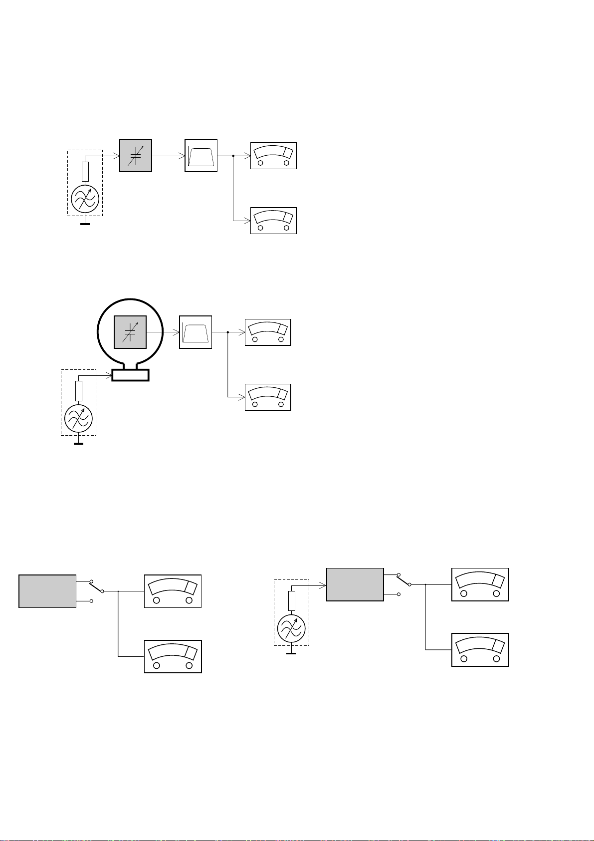
MEASUREMENT SETUP
Tuner FM
1-4
Bandpass
LF Voltmeter
e.g. PM2534
RF Generator
e.g. PM5326
DUT
250Hz-15kHz
e.g. 7122 707 48001
Ri=50Ω
S/N and distortion meter
e.g. Sound Technology ST1700B
Use a bandpass filter to eliminate hum (50Hz, 100Hz) and disturbance from the pilottone (19kHz, 38kHz).
Tuner AM (MW,LW)
RF Generator
e.g. PM5326
Ri=50Ω
DUT
Frame aerial
e.g. 7122 707 89001
Bandpass
250Hz-15kHz
e.g. 7122 707 48001
LF Voltmeter
e.g. PM2534
S/N and distortion meter
e.g. Sound Technology ST1700B
To avoid atmospheric interference all AM-measurements have to be carried out in a Faraday´s cage.
Use a bandpass filter (or at least a high pass filter with 250Hz) to eliminate hum (50Hz, 100Hz).
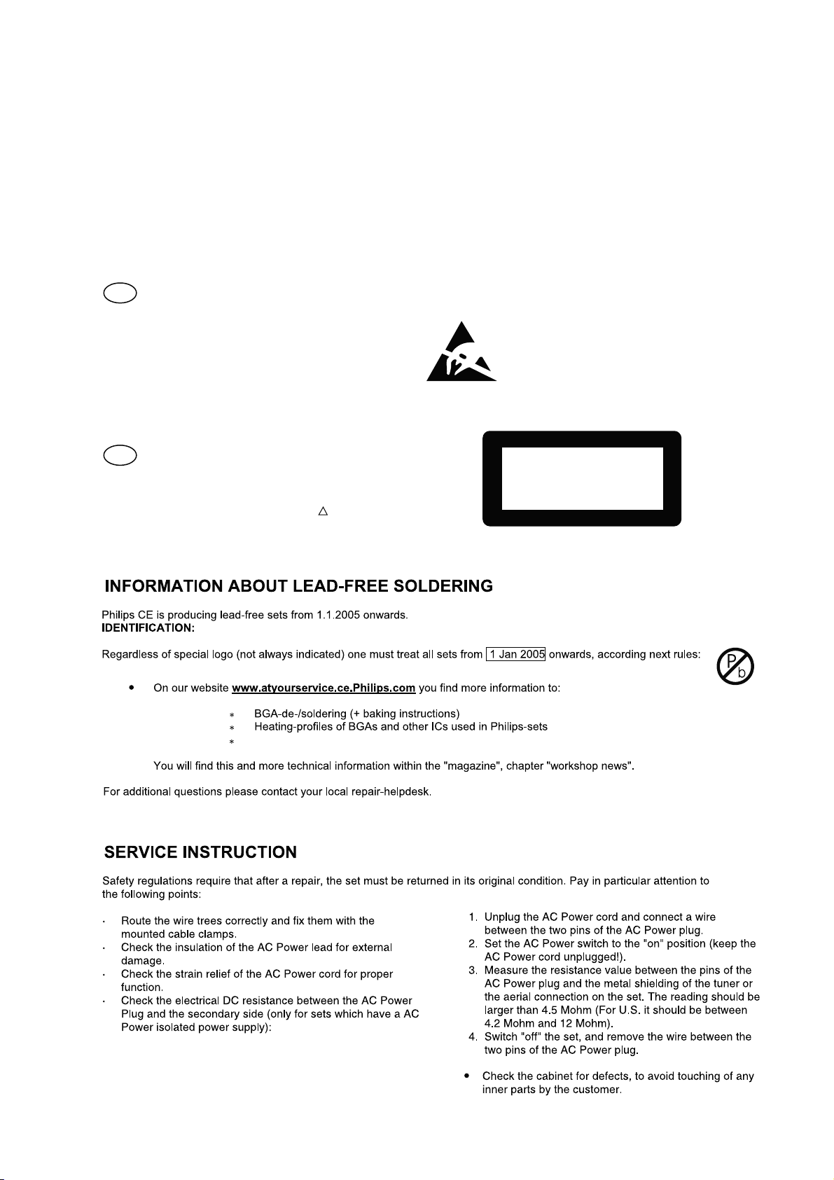
CD
Use Audio Signal Disc
(replaces test disc 3)
DUT
L
R
SBC429 4822 397 30184
S/N and distortion meter
e.g. Sound Technology ST1700B
LEVEL METER
e.g. Sennheiser UPM550
with FF-filter
Recorder
Use Universal Test Cassette CrO2 SBC419 4822 397 30069
or Universal Test Cassette Fe SBC420 4822 397 30071
LF Generator
e.g. PM5110
DUT
L
R
S/N and distortion meter
e.g. Sound Technology ST1700B
LEVEL METER
e.g. Sennheiser UPM550
with FF-filter
Page 5
SERVICE AIDS
1-5
Service Tools:
Universal Torx driver holder .................................4822 395 91019
Torx bit T10 150mm ...........................................4822 395 50456
Torx driver set T6-T20 .........................................4822 395 50145
Torx driver T10 extended .....................................4822 395 50423
GB
All ICs and many other semi-conductors are
susceptible to electrostatic discharges (ESD).
Careless handling during repair can reduce life
drastically.
When repairing, make sure that you are
connected with the same potential as the mass
of the set via a wrist wrap with resistance.
Keep components and tools also at this
potential.
WARNING
GB
Safety regulations require that the set be restored to its original
condition and that parts which are identical with those specified,
be used
Safety components are marked by the symbol
!
.
Compact Disc:
SBC426/426A Test disc 5 + 5A ...........................4822 397 30096
SBC442 Audio Burn-in test disc 1kHz .................4822 397 30155
SBC429 Audio Signals disc .................................4822 397 30184
Dolby Pro-logic Test Disc ....................................4822 395 10216
ESD
CLASS 1
LASER PRODUCT
Lead free
Page 6
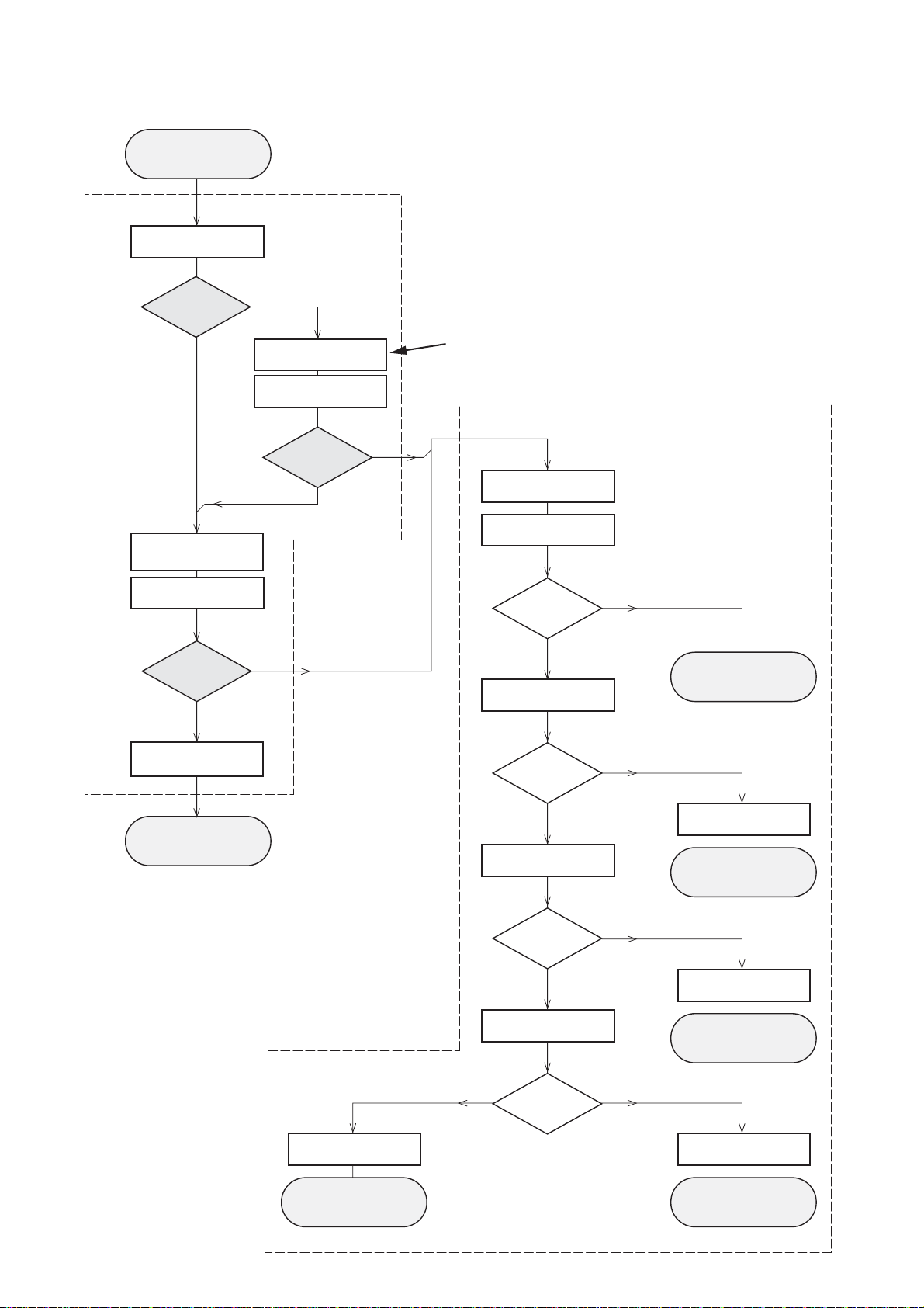
INSTRUCTIONS ON CD PLAYABILITY
Customer complaint
"CD related problem"
Set remains closed!
check playability
1
1-6
playability
ok ?
Y
Play a CD
for at least 10 minutes
check playability
playability
ok ?
Y
N
"fast" lens cleaning
check playability
playability
ok ?
N
3
For flap loaders (= access to CD drive possible)
cleaning method
4 is recommended
Standard repair procedure
N
Y
clean the lens
check playability
playability
ok ?
check "EYE-Pattern"
4
Y
N
5
return set
add Info for customer
"SET OK"
return set
1 - 7
For description - see following pages
2
replace Signal Processor
return set
EYE-Pattern
ok ?
Y
check Laser current
Laser current
ok ?
Y
check CD Drive offsets
Y
CD Drive offsets
ok ?
N
replace CD Drive
6
return set
N
replace CD Drive
7
return set
N
replace CD Drive
return set
Page 7
INSTRUCTIONS ON CD PLAYABILITY
1-7
1
PLAYABILITY CHECK
For sets which are compatible with CD-RW discs
use CD-RW Printed Audio Disc....................7104 099 96611
TR 3 (Fingerprint)
TR 8 (600µ Black dot) maximum at 01:00
• playback of these two tracks without audible disturbance
playing time for: Fingerprint ≥10seconds
Black dot from 00:50 to 01:10
• jump forward/backward (search) within a reasonable time
For all other sets
use CD-DA SBC 444A..................................4822 397 30245
TR 14 (600µ Black dot) maximum at 01:15
TR 19 (Fingerprint)
TR 10 (1000µ wedge)
• playback of all these tracks without audible disturbance
playing time for: 1000µ wedge ≥10seconds
Fingerprint ≥10seconds
Black dot from 01:05 to 01:25
• jump forward/backward (search) within a reasonable time
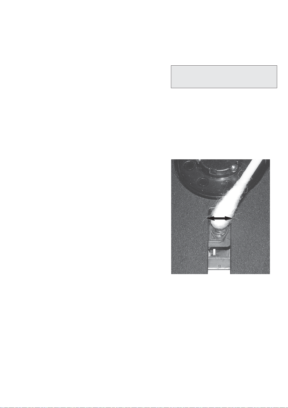
4
LIQUID LENS CLEANING
Before touching the lens it is advised to clean the
surface of the lens by blowing clean air over it.
This to avoid that little particles make scratches on
the lens.
Because the material of the lens is synthetic and coated
with a special anti-reflectivity layer, cleaning must be done
with a non-aggressive cleaning fluid. It is advised to use
“Cleaning Solvent B4-No2”, available with codenumber
4822 389 10026.
The actuator is a very precise mechanical component and
may not be damaged in order to guarantee its full function.
Clean the lens gently (don’t press too hard) with a soft and
clean cotton bud moistened with the special lens cleaner.
The direction of cleaning must be in the way as indicated in
the picture below.
2
CUSTOMER INFORMATION
It is proposed to add an addendum sheet to the set which
informs the customer that the set has been checked
carefully - but no fault was found.
The problem was obviously caused by a scratched, dirty or
copy-protected CD. In case problems remain, the customer
is requested to contact the workshop directly.
The lens cleaning (method 3) should be mentioned in the
addendum sheet.
The final wording in national language as well as the printing
is under responsibility of the Regional Service Organizations.
3
FAST LENS CLEANING (dry brush)
Use lens cleaning CD
SBC AC300...........................................9082 100 00043
Insert the lens cleaning CD, press PLAY and follow the
voice guide´s instructions on the CD.
Page 8
Sanyo DA12T3
CD Drive
A
A
F
C
B
E
C
D
E
VCC
B
VREF
F
D
9
10
11
12
13
14
15
16
1800
+5V_HF
VrefCD10
A
D
E
B
C
F
GND
8
E
D
A
B
C
F
Laser power control
100n
2878
470n
2876
3821
1R
1K
3823
2880
33p
+5V
BC807-40
7879
3817
47R
3820
4R7
47R
3819
1n
2879
2877
47u
1
8
4
7811-A
LM358D
3
2
10K
3822
47R
3818
2841
100n
47n
2869
+5V_HF
LASER DIODE
U >250mV
->Laser damaged !
4,6V
3V
3,3V
3,9V
2V
0,17V
0,17V
Sanyo
DA12T3
HF-Amplifier
D3
D2
D1
680R
3905
3903
3K3
BC847B
7877
47n
2818
1K5
3902
5
7
4
2
1
6
3
64
8
9
10
11
470R
3893
+3.3V
2K2
3908
10K
3923
BC847B
7878
BC847B
7876
4n7
2813
3896
100R
220u
2885
2881
560p
47n
2887
560R
3901
2883
470n
2817
4u7
3n3
2814
3898
220R
3895
27K
470n
2884
+3.3V
3909
820R
3907
100R
3920
33K
3897
2882
82p
3K3
3904
2K7
3899
3906
470R
+5V_HF
HFIN
VrefCD10
100p
28152816
22n
LDON
to 3826,3827
VREF GE
VDDA1
VRIN
VSSA1
ISLICE
LD
ON
D1
D2
D3
D4
HFIN
HFREF
IREF
CD_DA: 0V / CD_RW: 3V
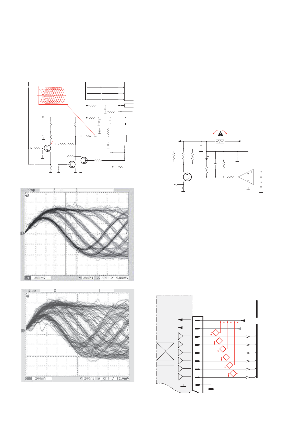
Σ (A-D)
800mVpp
TB = 0.5µs/div
EYE-PATTERN
1,8V
1,2V
2,4V
2,6V
0,65V
INSTRUCTIONS ON CD PLAYABILITY
1-8
5
EYE-PATTERN SIGNAL – JITTER MEASUREMENT
Measure the signal on the input of the Signal processor
using an analog oscilloscope. Please find the exact
measuring point in your Service Manual.
See below examples of the signal. Amplitude should read at
least 700mVpp using SBC444A.
6
CD DRIVE – LASER CURRENT MEASUREMENT
The laser current can be measured as a voltage drop on a
resistor. The resistor is marked in every Service Manual.
The value depends on the type of CD drive.
typical value most probably defect
VAMxxxx : 150-230mV ≥350mV
MCDxx : 170-230mV ≥300mV
DA1x : 210-250mV ≥350mV
DA2x : 175-200mV ≥250mV
Use SBC444A (CD-DA) for measurement.
If the oscilloscope shows a signal like the ‘bad’ one, and/or
the amplitude decreases within 1 minute - the CD drive has
to be replaced.
good
bad
7
CD DRIVE – OFFSET MEASUREMENT
The photodiodes of the CD-drive may have an offset. These
offsets have to be compensated by the signal processor.
High offsets can lead to poor playability of some CDs
(skipping tracks).
To measure the offset values, start the Service Test
Program - section “Focus Test” without a CD.
The offsets can be measured with a DC Millivoltmeter
directly on the connector (see drawing below). Pin
numbering varies from drive to drive.
The values from diode A-D should read 0±10mV.
Diodes E and F are less critical.
If one of the offsets is higher than ±10mV the CD drive has
to be replaced. Otherwise replace the Signal Processor.
Page 9
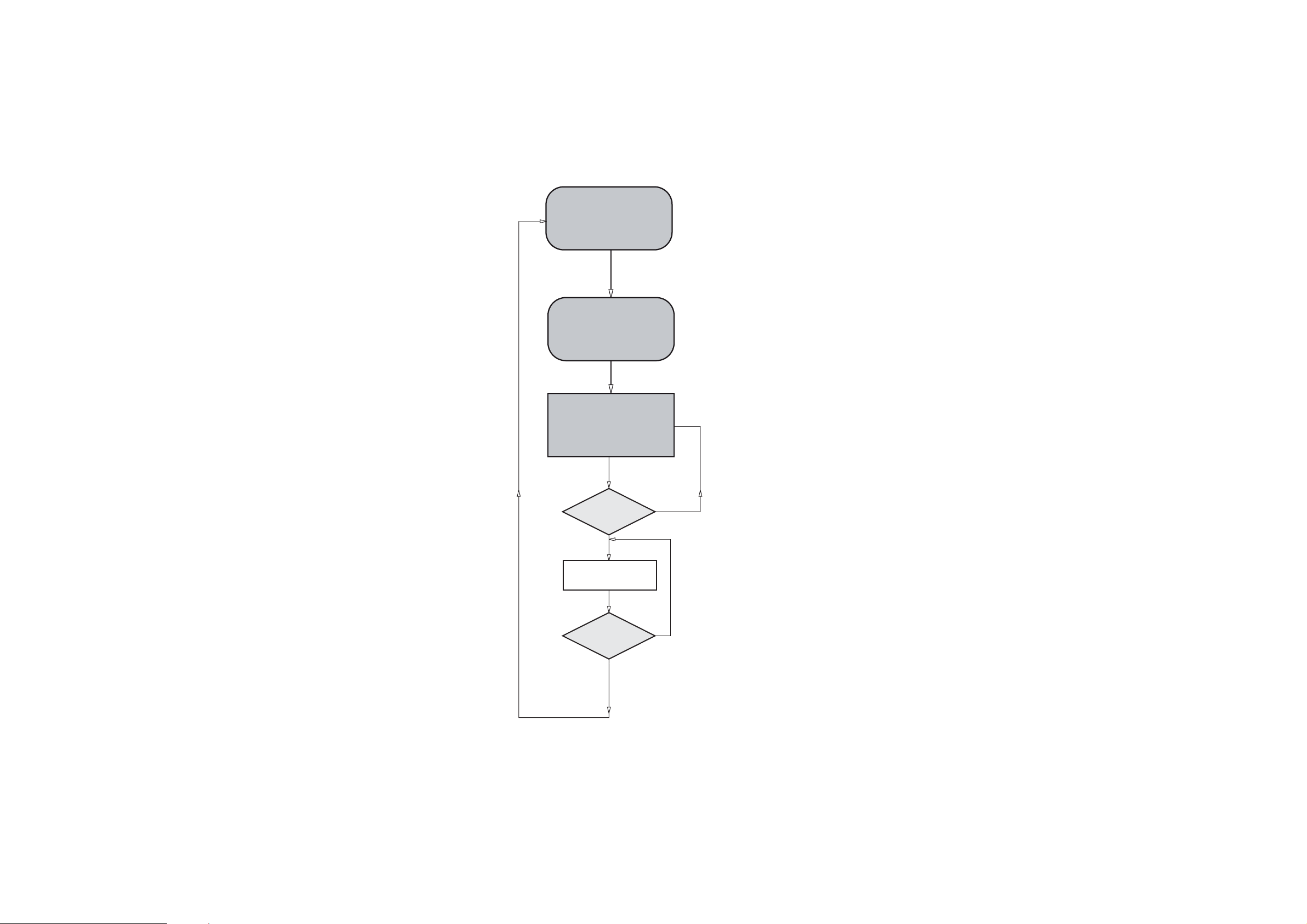
SOFTWARE VERSION CHECKING
2-1
Set on Standby.
T o hold REPEAT &
PRESET+ depressed
2-1
Display shows the
ROM version
"U - XX"
DISPLAY
TEST
PRESET-
Button pressed?
Y
Display shows all patterns
9
Button pressed?
Y
U refers to Version
XX refers to Software version number of the uProcessor
(counting up from 01 to 99)
N
N
Page 10

SET BLOCK DIAGRAM
3-1
3-1
Page 11

SET WIRING DIAGRAM
4-1
4-1
FRONT/MCU BOARD
MAINFRONT/MCU BOARD BOARD
CASS BOARD
Page 12

5-1 5-1
MAIN BOARD
TABLE OF CONTENTS
Layout Top View ..............................................................5-2
Layout Bottom View .........................................................5-3
Circuit Diagram (AF&Amp Part) .......................................5-4
Circuit Diagram (CD Part) .................................................5-5
Circuit Diagram (Tuner Part) ............................................5-6
Page 13

PCB LAYOUT - MAIN BOARD
TOP VIEW
5-2 5-2
Page 14

PCB LAYOUT - MAIN BOARD
BOTTOM VIEW
5-3 5-3
Page 15

CIRCUIT DIAGRAM - MAIN BOARD
AF & AMP PART
5-4
5-4
Page 16

CIRCUIT DIAGRAM - MAIN BOARD
CD PART
5-5
5-5
Page 17

CIRCUIT DIAGRAM - MAIN BOARD
TUNER PART
5-6
5-6
Page 18

6-1
FRONT BOARD
6-1
TABLE OF CONTENTS
Layout Top View ............................................................... 6-2
Layout Bottom View ..........................................................6-3
Circuit Diagram ................................................................. 6-4
Page 19

6-2
PCB LAYOUT - FRONT BOARD (TOP VIEW)
6-2
Page 20

6-3
PCB LAYOUT - FRONT BOARD (BOTTOM VIEW)
6-3
Page 21

CIRCUIT DIAGRAM - FRONT BOARD
6-4
6-4
Page 22

7-1
CASSETTE BOARD
7-1
TABLE OF CONTENTS
Layout Top View ............................................................... 7-2
Layout Bottom View ..........................................................7-2
Circuit Diagram ................................................................. 7-3
Page 23

7-2
7-2
PCB LAYOUT - CASSETTE BOARD (TOP VIEW)
PCB LAYOUT - CASSETTE BOARD (BOTTOM VIEW)
Page 24

7-3 7-3
CIRCUIT DIAGRAM - CASSETTE BOARD
Page 25

Micro System
MC157/61
TABLE OF CONTENTS
Page
Location of PCBs ..................................................................1-2
Speci cations .......................................................................1-3
Measurement Setup .............................................................1-4
Service Aids, Safety Instruction, etc .....................................1-5
CD Playability Check ..................................................1-6 to 1-8
Software Version Checking .....................................................2
Set Block Diagram ...................................................................3
Set Wiring Diagram .................................................................4
Main Board ..............................................................................5
Front Board..............................................................................6
Cass Board ..............................................................................7
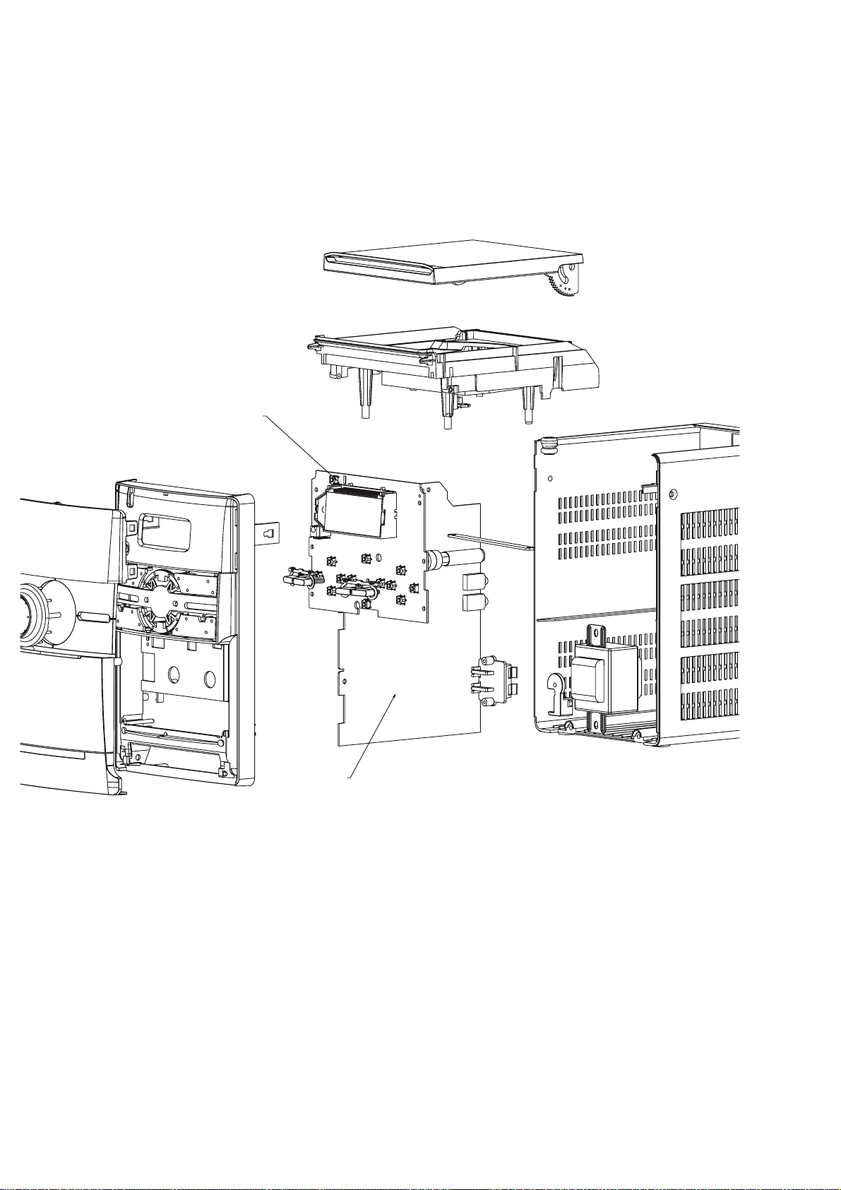
Set Mechanical Exploded View & Parts List ............................8
Electrical Parts List .................................................................. 9
Revision List ..........................................................................10
©
Copyright 2010 Philips Consumer Electronics B.V. Eindhoven, The Netherlands
All rights reserved. No part of this publication may be reproduced, stored in a retrieval system or
transmitted, in any form or by any means, electronic, mechanical, photocopying, or otherwise without
the prior permission of Philips.
Published by SL 1011 Service Audio Printed in The Netherlands Subject to modification
Version 1.1
CLASS 1
LASER PRODUCT
© 3141 785 32981
Page 26

8 - 2
MECHANICAL & ACCESSORIES PARTS LIST
5 996520032155 PCBA-CASS DECK MCM149/55
6 996510006838 REMOTE CONTROL
80 996510006840 CASS DECK JS-21FB8923-SGS
81 994000005398 CD MECHANISM DA11B3VF
114 994000003674 CD DOOR SPRING
115 996510000917 CASS SPRING
116 996510000918 CASSETTE KEY COVER SPRING
201 996510016982 FRONT CABINET
202 996510016984 REAR CABINET
203 996510029654 AC CORD BRACKET
204 996510029651 CD TRAY
205 996510016986 CASSETTE DOOR
206 996520034957 CD DOOR
207 996500039787 LASER COVER (FOR SANYO CD)
208 996510016988 CASS KEY DOOR
209 996510006846 VOL BUTTON COVER -5g
210 996510013807 SOURCE BUTTON COVER
211 996510013804 DBB BUTTON COVER
212 996510013808 PLAY BUTTON COVER
213 996510013810 STOP BUTTON COVER
214 996510013805 VOL COSMETI COVER
215 994000001295 DAMPER GEAR ASSY
216 996510016995 PROGRAM/REPEAT BUTTON
217 996510006662 POWER BUTTON
218 996510013811 PRESET BUTTON
219 996510006853 CASS KEY WITH HOLDER
220 996510016999 DISPLAY LENS
J001 994000004487 16P FFC CABLE L170MM
J002 996510008608 17P FLAT FLEXCBL 1.25MM L100MM
J008 996510006841 15P FFC 1MM L260MM
J011 ! 996510007312 AC CORD KS APP 1.92M
J012 996510000910 FM ANT SMF-01T-1.3 L=1.1M
J013 996510011385 NUT WIRE CONNECTOR
S001 996510010912 SINGLE SPK BOX
T001 ! 996510006839 TRANSFORMER EI48 230V
Note: Only these parts mentioned in the list are
normal service parts.
Page 27

9-1
ELECTRICAL PARTS LIST - MAIN BOARD
111 996510002038 FM ANT CONTACT PIN Q9 996500038609 TRANSISTORS 2W 8050C
112 996510002038 FM ANT CONTACT PIN T2 996510006835 I.F.T 7mm 660R (RED)
C16 996510006833 E.CAP 3300UF 25V +-20% T3 994000002861 I.F.T 7MM A049 (YELLOW)
CF1 996510006834 DISCRI.FILTER CDA10.7MG46-A U101 994000003636 IC D8227 DIP
CF2 994000003642 CER. FILTER LT10.7MA5-A RED U2 994000004532 IC KA7808E
CF3 994000002857 CERAMIC FILTER SFU450B U33 996510003984 IC CYT78L05 (TO-92)
CON3 996510005450 SPK JACK PT-22V11A VD1 994000002836 VARICAP DIODE 1SV-149
CT1 994000000254 TRIMMER 10PF 6MM (WH) VD2 994000002836 VARICAP DIODE 1SV-149
CT2 994000000254 TRIMMER 10PF 6MM (WH) VD3 994000004342 VARICAP DIODE V101
D6 994000003938 RECTIFIER DIODE RL-202 VD4 994000004342 VARICAP DIODE V101
D7 994000003938 RECTIFIER DIODE RL-202 X1 994000004551 CRYSTAL 16.9344MHZ +-20PPM
D8 994000003938 RECTIFIER DIODE RL-202
D9 994000003938 RECTIFIER DIODE RL-202
F1 ! 994000000586 GLASS FUSE W/LEAD 3.15A/250V
IC1 996510006827 IC (SANYO) LA6541NHL-TE-L-E
IC2 996500039806 IC ET2314 (SOP28) Note: Only these parts mentioned in the list are
IC3 996510006828 IC (SANYO) LA9242M-MPB-E normal service parts.
IC4 996510006829 IC (SANYO) LC78602RE-8616
IC5 996510006832 IC (SANYO) LA1823
JACK1 994000004369 PHONE JACK TC38-063-05-0
JACK2 996510000889 PHONE JACK TC38-060-01 RING
L001 996510006681 AM COIL AD/M7 65:20T
L1 996500039350 FM COIL 4.5x2.5T (0.8mm)
L7 994000003655 FM COIL 4.5X3.5T
L8 994000003655 FM COIL 4.5X3.5T
Q1 994000003937 TRANSISTORS PMBT3906
Q10 996500038609 TRANSISTORS 2W 8050C
Q11 994000004145 TRANSISTORS B772Y (160-320)
Q12 994000004338 SMD TRANSISTORS PMBT3904
Q13 994000003937 SMD TRANSISTORS PMBT3906
Q14 996510003996 TRANSISTORS KTA1273
Q15 996500038609 TRANSISTORS 2W 8050C
Q16 996510006831 TRANSISTORS 9018F
Q17 996510006831 TRANSISTORS 9018F
Q18 996510006831 TRANSISTORS 9018F
Q20 996500038609 TRANSISTORS 2W 8050C
Q21 994000004338 SMD TRANSISTORS PMBT3904
Q22 994000004145 TRANSISTORS B772Y (160-320)
Q25 994000004338 SMD TRANSISTORS PMBT3904
Q3 994000004338 SMD TRANSISTORS PMBT3904
Q4 994000004338 SMD TRANSISTORS PMBT3904
Q5 996500038609 TRANSISTORS 2W 8050C
Q6 994000003937 SMD TRANSISTORS PMBT3906
Q7 994000004338 SMD TRANSISTORS PMBT3904
Q8 996510006830 TRANSISTORS 2SD882P
Page 28

9-2
ELECTRICAL PARTS LIST - FRONT BOARD
D41 996500042438 LED LAMP 2x5x7mm (WHITE)
L1 996510006837 AXIAL INDUCTOR 10UH +-10%
Q21 994000004338 SMD TRANSISTORS PMBT3904
Q26 994000004338 SMD TRANSISTORS PMBT3904
Q27 994000004338 SMD TRANSISTORS PMBT3904
Q6 994000003937 SMD TRANSISTORS PMBT3906
RE1 994000004367 OPTIC SENSER FM-6038TM2-5AN
SW1 994000001243 TACT SWITCH
SW10 994000001243 TACT SWITCH
SW11 994000001243 TACT SWITCH
SW12 994000001243 TACT SWITCH
SW13 994000001243 TACT SWITCH
SW2 994000001243 TACT SWITCH
SW3 994000001243 TACT SWITCH
SW4 994000001243 TACT SWITCH
SW5 994000001243 TACT SWITCH
SW6 994000001243 TACT SWITCH
SW7 994000001243 TACT SWITCH
SW8 994000001243 TACT SWITCH
SW9 994000001243 TACT SWITCH
U1 994000004541 IC M24C02-WMN6
U3 996510006836 MCU GY550 (OTP)
XT1 994000004616 CRYSTAL 4.500MHZ
XT2 996500042441 X'TAL 32.768KHZ -20PPM
LCD1 996510008371 LCD DISPLAY SDH-DA1607-TN-1
ELECTRICAL PARTS LIST - CASS BOARD
IC505 994000004533 IC YD7312
L25 994000004538 I.F.T 10148BK7
Q511 994000004338 TRANSISTORS PMBT3904
Q512 996500038609 TRANSISTORS 2W 8050C
SW201 994000003656 PUSH SWITCH PS-102D13-NS
Note: Only these parts mentioned in the list are
normal service parts.
Page 29

REVISION LIST
V
Version 1.0 (3141 785 32980)
* Initial Release
V
Version 1.1 (3141 785 32981 )
* P8-2 is revised.Changed some mechanical partlist(204,203,206,209,210,211,212,213,214,217,218,219).
10-1
 Loading...