

Page 1

Micro System
MC138/all
TABLE OF CONTENTS
Page
Handling chip components ...........................................1-1
Technical Specifications ...............................................2-1
Service Tool ..................................................................2-1
Measurement setup .....................................................2-2
Connections and Controls ................................... 3-1.. 3-2
Disassembly diagram ...................................................4-1
Pin description of ICs ...........................................4-2 ..4-4
Set Block diagram ........................................................5-1
Set Wiring diagram .......................................................5-2
Combi board - Circuit diagram
LCD/HP/KEY/POWER board ....................................6-1
Tuner board ...............................................................6-2
Main board ................................................................6-3
Combi borad - Layout diagram ...........................6-4 .. 6-5
CD board - Circuit diagram ..........................................7-1
CD board - Layout diagram ..........................................7-2
Cassette board - Circuit diagram .................................8-1
Cassette board - Layout diagram .................................8-2
Set Mechanical Exploded view ...................................9-1
Service parts list ............................................... 10-1..10-2
Revision list ................................................................11-1
©
Copyright 2005 Philips Consumer Electronics B.V. Eindhoven, The Netherlands
All rights reserved. No part of this publication may be reproduced, stored in a retrieval system or
transmitted, in any form or by any means, electronic, mechanical, photocopying, or otherwise without
the prior permission of Philips.
Published by YM 0519 Service Audio Printed in The Netherlands Subject to modification
Version 1.1
© 3141 785 30321
Page 2

HANDLING CHIP COMPONENTS
ANDLING CHIP COMPONENTS
1 - 1
©
WARNING
All ICs and many other semiconductors are susceptible to
electrostatic discharges (ESD). Careless handling during
repair can reduce life drastically.
When repairing, make sure that you are connected with the
same potential as the mass of the set via a wristband with
resistance. Keep components and tools at this potential.
f
ATTENTION
Tous les IC et beaucoup d´autres semi-conducteurs sont
sensibles aux décharges statiques (ESD). Leur longévite
pourrait être considérablement écourtée par le fait qu´aucune
précaution nést prise à leur manipulation.
Lors de réparations, s´assurer de bien être relié au même
potentiel que la masse de l´appareil et enfileer le bracelet
serti d´une résistance de sécurité.
Veiller à ce que les composants ainsi que les outils que l´on
utilise soient également à ce potentiel.
©
Safety regulations require that the set be restored to its
original condition and that parts which are identical with
those specified be used.
Safety components are marked by the symbol
f
Les normes de sécurité exigent que l`appareil soit remis
à l`état d`origine et que soient utilisées les pièces de
rechange identiques à celles spécifiées.
Les composants de sécurité sont marqués
d
Alle ICs und viele andere Halbleiter sind empfindlich
gegenüber elektrostatischen Entladungen (ESD).
Unsorgfältige Behandlung im Reparaturfall kann die
Lebensdauer drastisch reduzieren.
Sorgen Sie dafür, daß Sie im Reparaturfall über ein Pulsarmband mit Widerstand mit dem Massepotential des
Gerätes verbunden sind.
Halten Sie Bauteile und Hilfsmittel ebenfalls auf diesem
Potential.
d
Bei jeder Reparatur sind die geltenden Sicherheitsvorschriften zu beachten. Der Originalzustand des Gerätes
darf nicht verändert werden. Für Reparaturen sind Originalersatzteile zu verwenden.
Sicherheitsbauteile sind durch das Symbol markiert.
WARNUNG
ESD
SAFETY
ñ
WAARSCHUWING
Alle IC´s en vele andere halfgeleiders zijn gevoelig voor
electrostatische ontladingen (ESD).
Onzorgvuldig behandelen tijdens reparatie kan de levensduur
drastisch doen vermindern. Zorg ervoor dat u tijdens reparatie
via een polsband met weerstand verbonden bent met hetzelfde
potentiaal als de massa van het apparaat.
Houd componenten en hulpmiddelen ook op ditzelfde potentiaal.
i
AVVERTIMENTO
Tutti IC e parecchi semi-conduttori sono sensibili alle scariche
statiche (ESD).
La loro longevità potrebbe essere fortemente ridatta in caso di
non osservazione della più grande cauzione alla loro
manipolazione. Durante le riparationi occorre quindi essere
collegato allo stesso potenziale che quello della massa
delápparecchio tramite un braccialetto a resistenza.
Assicurarsi che i componenti e anche gli utensili con quali si
lavora siano anche a questo potenziale.
ñ
Veiligheidsbepalingen vereisen, dat het apparaat in zijn
oorspronkeliijke toestand wordt teruggebracht en dat
onderdelen, identiek aan de gespecificeerde, worden toegepast.
De Veiligheidsonderdelen zijn aangeduid met het symbool
i
Le norme di sicurezza estigono che l´apparecchio venga
rimesso nelle condizioni originali e che siano utilizzati i
pezzi di ricambiago identici a quelli specificati.
Componenty di sicurezza sono marcati con
©
DANGER: Invisible laser radiation when open.
AVOID DIRECT EXPOSURE TO BEAM.
s
Varning !
Osynlig laserstrålning när apparaten är öppnad och
spärren är urkopplad. Betrakta ej strålen.
ñ
Advarsel !
Usynlig laserstråling ved åbning når sikkerhedsafbrydere
er ude af funktion. Undgå udsaettelse for stråling.
CLASS 1
LASER PRODUCT
Varoitus !
Avatussa laitteessa ja suojalukituksen ohitettaessa olet alttiina
näkymättömälle laserisäteilylle. Älä katso säteeseen !
©
After servicing and before returning the set to customer
perform a leakage current measurement test from all
exposed metal parts to earth ground, to assure no
shock hazard exists.
The leakage current must not exceed 0.5mA.
f
"Pour votre sécurite, ces documents doivent être utilisés par
des spécialistes agréés, seuls habilités à réparer votre
appareil en panne".
Page 3

2 - 1
Page 4
SERVICE MEASUREMENT
2 - 2
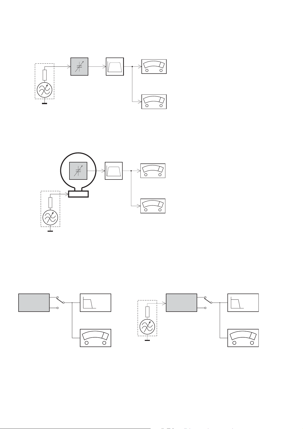
Tuner FW
RF Generator
e.g. PM5326
DUT
Bandpass
250Hz-15kHz
e.g. 7122 707 48001
LF Voltmeter
e.g. PM2534
½
Ri=50
S/N and distortion meter
e.g. Sound Technology ST1700B
Use a bandpass filter to eliminate hum (50Hz, 100Hz) and disturbance from the pilottone (19kHz, 38kHz).
Tuner AM (MW,LW)
RF Generator
e.g. PM5326
½
Ri=50
DUT
Frame aerial
e.g. 7122 707 89001
Bandpass
250Hz-15kHz
e.g. 7122 707 48001
LF Voltmeter
e.g. PM2534
S/N and distortion meter
e.g. Sound Technology ST1700B
To avoid atmospheric interference all AM-measurements have to be carried out in a Faraday«s cage.
Use a bandpass filter (or at least a high pass filter with 250kHz) to eliminate hum (50Hz, 100Hz).
CD RECORDER
Use Audio Signal Disc SBC429 4822 397 30184
(replaces test disc 3)
DUT
L
R
S/N and distortion meter
e.g. Sound Technology ST1700B
LEVEL METER
e.g. Sennheiser UPM550
with FF-filter
Use Universal Test Cassette Fe SBC420 4822 397 30071
LF Generator
e.g. PM5110
DUT
½
Ri=50
L
R
S/N and distortion meter
e.g. Sound Technology ST1700B
LEVEL METER
e.g. Sennheiser UPM550
with FF-filter
Page 5
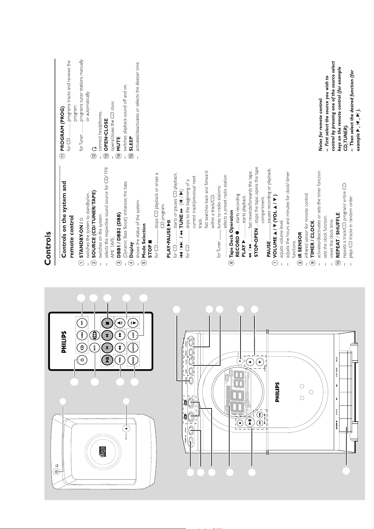
CONTROLS AND CONTROLS
3 - 1
@
1
2
3
$
5
!
7
#
0
RW COMPATIBLE
-
R/CD
-
CD/CD
%
!
1
0
263
9
4
8
7
5
Page 6
CONTROLS AND CONTROLS
3 - 2
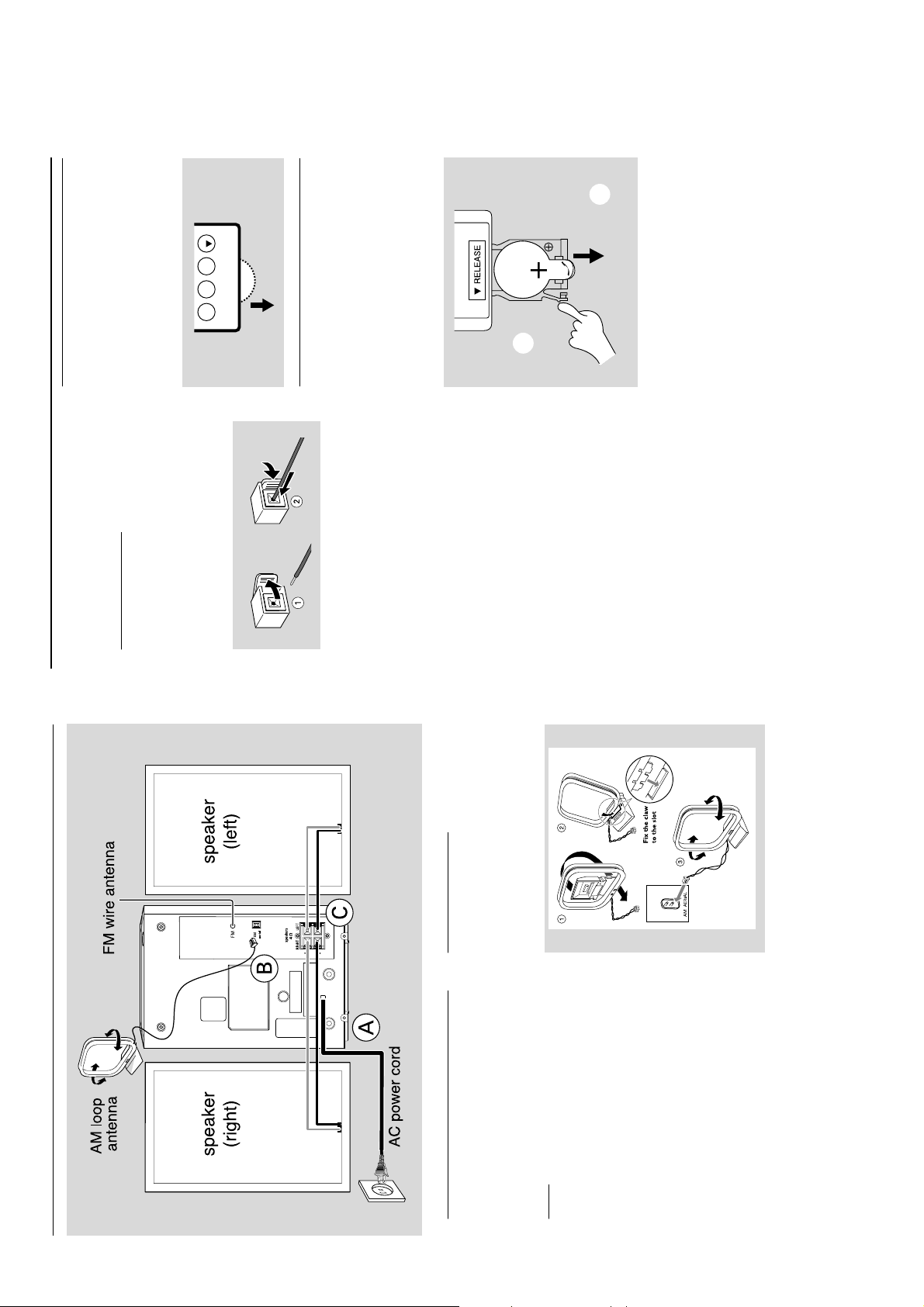
Preparations
Before using the remote control
Pull out the plastic protective sheet.2Select the source you wish to control by
pressing one of the source select keys on the
1
FM Antenna
Extend coil antenna at the back of the unit fully
for optimum reception.CSpeakers Connection
VOL
SLEEP
SHUFFLE
REPEAT
™ ).
¡ ,
remote control (for example CD, TUNER).3Then select the desired function (for example
2 ,
Front Speakers
Connect the speaker wires to the SPEAKERS
terminals, right speaker to "RIGHT" and left
speaker to "LEFT", coloured (marked) wire to
.
B
slightly to the right.
B
PULL
A
A
PUSH
Replacing battery (lithium
CR2025) into the remote control
Pull out the knob
Pull out the battery compar tment
Replace a new battery and fully inser t the
battery compar tment back to the original
position.
2
3
1
speaker terminals.
-
/
+
"+ " and black (unmarked) wire to "- ".
Fully insert the stripped portion of the speaker
wire into the terminal as shown.
Notes:
– For optimal sound performance, use the
supplied speakers.
– Do not connect more than one speaker to any
one pair of
– Do not connect speakers with an impedance
lower than the speakers supplied. Please refer to
the SPECIFICATIONS section of this manual.
CAUTION!
Batteries contain chemical substances, so
they should be disposed off properly.
Preparations
Antennas Connection
Connect the supplied AM loop antenna and FM
antenna to the respective terminals. Adjust the
position of the antenna for optimal reception.
AM Antenna
B
Rear connections
The type plate is located at the rear of the
system.
For users in the U.K.: please follow the
instructions on page 2.
Powe r
Before connecting the AC power cord to the
wall outlet, ensure that all other connections
have been made.
WARNING!
– For optimal performance, use only the
A
original power cable.
– Never make or change any connections
with the power switched on.
To avoid overheating of the system, a safety
circuit has been built in. Therefore, your
system may switch to Standby mode
Position the antenna as far as possible from a TV,
VCR or other radiation source.
automatically under extreme conditions. If
this happens, let the system cool down
before reusing it (not available for all versions).
Page 7
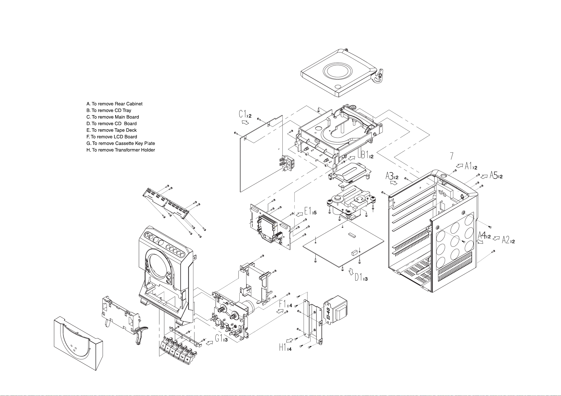
DISASSEMBLY DIAGRAM
4 - 1 4 - 1
Page 8

4 - 2
4 - 2
Page 9

4 - 3 4 - 3
Page 10

4 - 4
4 - 4
Page 11

SET BLOCK DIAGRAM
5 - 1
5 - 1
Page 12

SET WIRING DIAGRAM
5 - 2
5 - 2
(YD7312)
D8227
Page 13

CIRCUIT DIAGRAM - COMBI BOARD
- LCD/KEY/HP/POWER PART
6 - 16 - 1
Page 14

CIRCUIT DIAGRAM - COMBI BOARD - TUNER PART
6 - 26 - 2
Page 15

CIRCUIT DIAGRAM - COMBI BOARD - MAIN BOARD PART
6 - 36 - 3
Page 16

LAYOUT DIAGRAM - COMBI BOARD COMPONET SIDE
6 - 46 - 4
Page 17

LAYOUT DIAGRAM - COMBI BOARD COPPER SIDE
6 - 56 - 5
Page 18

CIRCUIT DIAGRAM - CD BOARD
7 - 17 - 1
Page 19

LAYOUT DIAGRAM - CD BOARD
7 - 27 - 2
COMPONENT SIDE
COPPER SIDE
Page 20

CIRCUIT DIAGRAM - CASSETTE BOARD
8 - 18 - 1
Page 21

8 - 2
C
LAYOUT DIAGRAM - CASSETTE BOARD
12345
8 - 2
A
B
C
D
71
A
+M
-M
74
2734
3742
7702
3747
3730
2732
3732
2733
9754
9762
9755
2730
ECO- MTF- SD
2712
RSH
R- 1
2760
2735
6704
3731
2710
2703
2731
5701
2727
3744
2711
2726
9707
9701
3712
6715
3701
9760
3743
3733
2707
3707
7705
2722
2723
3761
2751
3719
9751
3720 3721
2704
2719
2716
3713
3716
R P
98- 12- 15
2706
2715
2750
2709
9703
1707
3726
3727
3711
9702
3140 113 31231
7703
3710
2708
3706
3762
2713
2718
3704
2717
2720
9705
3735
W
9756
9757
R
3714
2721
YSH
ECO- MTF- SD
7704
7701
3728
3703
2700
2728
3740
2729
3749
2739
2740
3750
2738 3734
98- 12- 15
73
3724
3739
27012714
9761
3723
3737
9759
3748
3722
3738
1701
1702
1722
1721
1725
9706
9753
3736
9752
1709
9758
72
98- 12- 15
71 A 1
72 D 5
73 A 5
74 A 1
1701 A 5
1702 B 5
3140 113 31231
A
B
C
D
1707 D 3
1709 C 5
1721 B 5
1722 B 5
1725 C 5
2700 B 4
2701 B 5
2703 C 2
2704 A 3
2706 A 3
2707 B 2
2708 B 4
2709 C 3
2710 B 1
2711 B 2
2712 D 1
2713 B 3
2714 B 4
2715 B 3
2716 B 3
2717 C 3
2718 B 3
2719 A 3
2720 C 3
2721 C 4
2722 C 2
2723 C 2
2726 C 2
2727 D 2
2728 C 5
2729 C 5
2730 D 1
2731 C 1
2732 B 1
2733 C 1
2734 A 1
2735 A 1
2738 D 4
2739 C 4
2740 C 4
2750 B 3
2751 C 2
2760 A 2
3701 A 2
3703 B 4
3704 B 4
3706 B 3
3707 B 2
3710 A 3
3711 C 3
3712 D 1
3713 C 3
3714 C 4
3716 C 3
3719 C 2
3720 D 2
3721 D 3
3722 D 5
3723 C 5
3724 A 5
3726 A 3
3727 A 3
3728 A 4
3730 B 1
3731 B 1
3732 B 1
3733 B 2
3734 D 5
3735 D 3
3736 B 5
3737 C 5
3738 C 5
3739 A 5
3740 B 4
3742 B 1
3743 A 2
3744 B 2
3747 B 1
3748 D 4
3749 C 5
3750 D 4
3761 C 2
3762 B 3
5701 C 1
6704 B 2
6715 A 2
7701 B 4
7702 B 1
7703 A 4
7704 A 4
7705 B 3
9701 D 2
9702 D 3
9703 D 3
9705 C 4
9706 D 5
9707 C 2
9751 D 3
9752 D 5
9753 D 5
9754 C 1
9755 D 1
9756 C 3
9757 D 3
9759 D 4
9760 A 2
9761 B 5
9762 D 1
T701 C 5
T702 C 5
T705 B 5
T706 B 5
T709 A 5
T710 C 1
T711 B 5
T712 C 2
T713 A 5
T714 D 5
T715 D 5
T716 D 1
T719 B 1
T720 A 5
T721 C 5
T722 C 2
T725 D 2
T7707 A 4
T7708 A 4
CASSETTE ADJUSTMENT
Adjustment Cassette SK .... Deck 1 Measure Read Adjust Adjust
Azimuth
Motor
Speed
10 kHz
SBC420*
3150 kHz
SBC420*
12345
on on with to
Left hand
Tape Play H/P Jack mV meter
Wow and
Tape Play H/P Jack flutter
meter
Screw
R/P head
Preset
in motor
max.
**a
* SBC420 : 4822 397 30071
**a The maximum permissible speed deviation is ± 3%.
Morever, the wow and flutter value can be read.
Page 22

SET EXPLODED VIEW DIAGRAM
9 - 1 9 - 1
21
19
W LIST
SCRE
ITEM
4
DESCRIPTION
QUANTITY
23
12
22
26
28
24
18
17
24
26
9
8
11
29
7
6
27
22
16
14
13 -1
13 -6
Page 23

10 - 1
T
MECHANICAIL & ACCESSORIES PARTSLIS
1 9940 000 01497 COSMETIC PANEL 9940 000 01344 SPEAKER BOX 3W MC138 W/MID
2 9940 000 00397 LENS 9940 000 01345 REMOTE CONTROL UNIT MC138
3 9940 000 01496 LCD CHAMFER 9940 000 00509 AM LOOP ANT
4 9940 000 00395 KEYSET TOP
6 9940 000 01498 CASSETTE PANEL
7 9940 000 00402 CASSETTE DOOR
8 9940 000 01494 FRONT CABINET
9 9940 000 00399 KNOB PLAY
11 9940 000 00401 KNOB VOLUME
12 9940 000 01488 LCD PWB ASSEMBLY MC138
13-1 9940 000 00404 CASSETTE KEY RECORD
13-2 9940 000 00405 CASSETTE KEY PLAY
13-3 9940 000 00406 CASSETTE KEY REVERSE
13-4 9940 000 00407 CASSETTE KEY FORWARD
13-5 9940 000 00408 CASSETTE KEY STOP/OPEN
13-6 9940 000 00409 CASSETTE KEY PAUSE
14 9940 000 01493 CASS DECK CS-21SC-820S
16 POWER TRANSFORMER AC120V
17 9940 000 00381 CD MECHANISM DA11B3N
18 9940 000 00392 REAR CABINET
19 9940 000 00502 CD DOOR SPRING
21 9940 000 01495 CD DOOR
22 9940 000 00501 DAMPER GEAR ASSEMBLY
23 9940 000 00394 CD TRAY
24 9940 000 00505 CD DAMPER 658 TA 30
26 9940 000 00506 CD DAMPER 658 TB 40
27 9940 000 00503 CASSETTE DOOR SPRING
28 9940 000 00379 CD DOOR SW DLS-02-W-1
Page 24

ELECTRICAL PARTSLIST
VC402 9940 000 00378 TRIMMER CAP 10pF +50%-0%
VC403 9940 000 00378 TRIMMER CAP 10pF +50%-0%
D407 9940 000 00376 VARIABLE CAP DIODE, BB804
D408 9940 000 00376 VARIABLE CAP DIODE, BB804
U402 9940 000 00375 VARIABLE CAP DIODE
U100 9940 000 00369 IC L7806CV REGULATOR
U102 9940 000 00372 IC P87C54X2BDH
U4 9940 000 00564 IC SAA7379HL
U401 9351 740 80557 IC SM TEA5757H/V1
U9 9940 000 00565 IC D9258 MOTOR DRIVER
7705 9940 000 01634 IC YD7312CP PREAMP.
1707 9940 000 00389 REC SWITCH 18PIN
S300 9940 000 00568 TACT SWITCH
S301 9940 000 00568 TACT SWITCH
S302 9940 000 00568 TACT SWITCH
S303 9940 000 00568 TACT SWITCH
S304 9940 000 00568 TACT SWITCH
S305 9940 000 00568 TACT SWITCH
S306 9940 000 00568 TACT SWITCH
S307 9940 000 00568 TACT SWITCH
10 - 2
S308 9940 000 00568 TACT SWITCH
S309 9940 000 00568 TACT SWITCH
S310 9940 000 00568 TACT SWITCH
S311 9940 000 00568 TACT SWITCH
S312 9940 000 00568 TACT SWITCH
S314 9940 000 00568 TACT SWITCH
S315 9940 000 00568 TACT SWITCH
HP800 9940 000 00386 HP JACK MSJ-2000
SP-JK 9940 000 00511 SP TERMINAL MSP-134V-05
9940 000 00373 FFC CABLE 16PIN P1.0 L70
F701
F702
! 9940 000 00637 FUSE PTU 1A 250V
! 9940 000 01492 FUSE SGP 1.25A 250V
! 9940 000 01491 TRANSFORMER AC120V
! 9940 000 02209 TRANSFORMER AC120/230V
! 9940 000 02224 TRANSFORMER 230V
! 9940 000 01489 POWER AC WIRE UL (/77)
! 9940 000 02223 POWER AC WIRE BS (/25)
! 9940 000 02225 POWER AC WIRE AR (/77)
! 9940 000 00382 POWER AC WIRE VDE (/21)
Page 25

11 - 1
REVISION LIST
Version 1.0 (3140 785 30320)
· Initial Release MC138/37
Version 1.1 (3140 785 30321)
· Introduction of MC138/21 /25 /77
· Page 2-1 : Technical Specifi cation adapted
· Page 10-1 : Service Parts List adapted
 Loading...