

Page 1

Micro System
�
MC108,MC108B/
all
TABLE OF CONTENTS
Page
Handling chip components ..........................................1-1
Technical Specications ..............................................2-1
Service Tool .................................................................2-1
Measurement setup .....................................................2-2
Connections and Controls ................................... 3-1.. 3-2
Set Block diagram .......................................................4-1
Set Wiring diagram ...................................................... 4-2
Disassembly diagram .................................................. 5-1
Main board - Circuit diagram
CD part ..................................................................... 6-1
Tuner part .................................................................6-2
Main borad - Layout diagram..............................6-3 .. 6-4
Display board - Circuit diagram ................................... 7-1
Display board - Layout diagram..........................7-2 .. 7-3
Set Mechanical Exploded view ...................................8-1
Mechanical Service parts list ...................................... 8-2
Electrical Service parts list..................................9-1 .. 9-2
Revisionlist................................................................10-1
©
Copyright 2006 Philips Consumer Electronics B.V. Eindhoven, The Netherlands
All rights reserved. No part of this publication may be reproduced, stored in a retrieval system or
transmitted, in any form or by any means, electronic, mechanical, photocopying, or otherwise without
the prior permission of Philips.
Published by LX 0 7 15- Service Audio Printed in The Netherlands Subject to modication
Version 1.2
© 3141 785 30992
Page 2
1 - 1
1 - 1
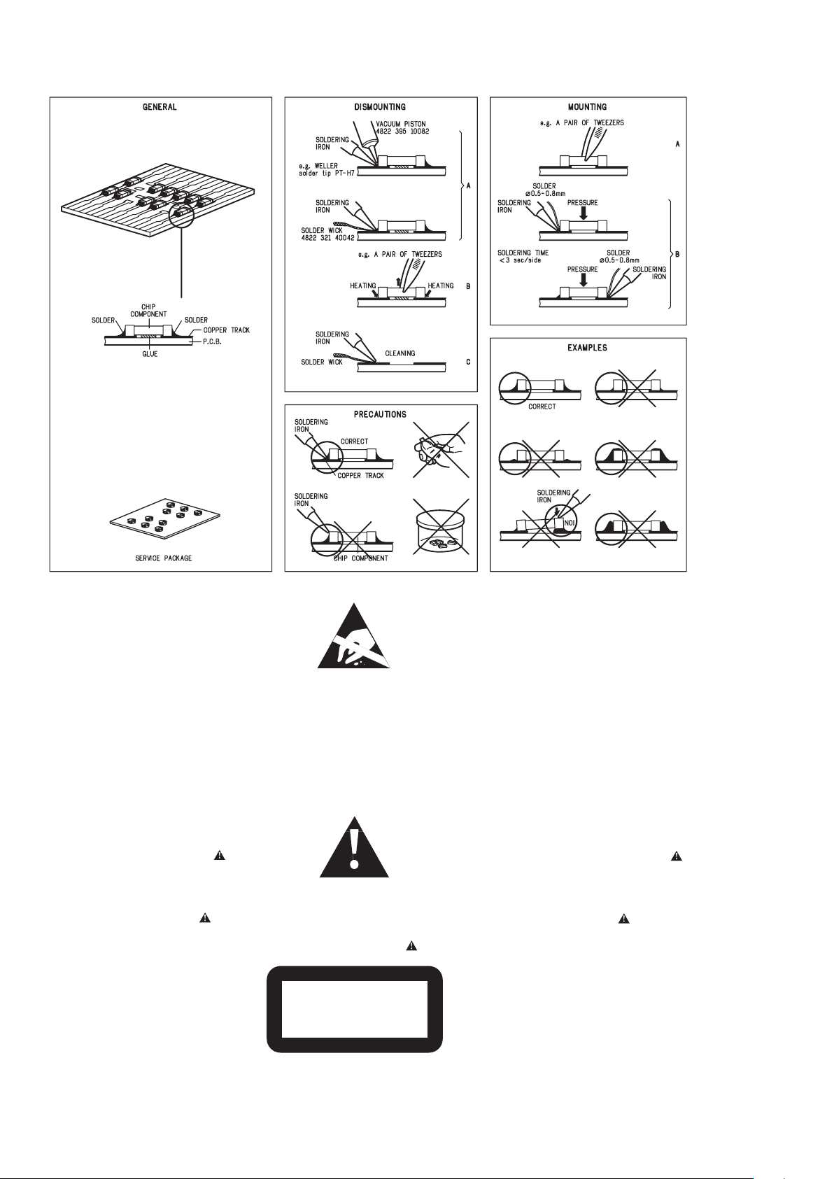
ANDLING CHIP COMPONENTS
©
WARNING
All ICs and many other semiconductors are susceptible to
electrostatic discharges (ESD). Careless handling during
repair can reduce life drastically.
When repairing, make sure that you are connected with the
same potential as the mass of the set via a wristband with
resistance. Keep components and tools at this potential.
f
ATTENTION
Tous les IC et beaucoup d´autres semi-conducteurs sont
sensibles aux décharges statiques (ESD). Leur longévite
pourrait être considérablement écourtée par le fait qu´aucune
précaution nést prise à leur manipulation.
Lors de réparations, s´assurer de bien être relié au même
potentiel que la masse de l´appareil et enfileer le bracelet
serti d´une résistance de sécurité.
Veiller à ce que les composants ainsi que les outils que l´on
utilise soient également à ce potentiel.
d
WARNUNG
Alle ICs und viele andere Halbleiter sind empfindlich
gegenüber elektrostatischen Entladungen (ESD).
Unsorgfältige Behandlung im Reparaturfall kann die
Lebensdauer drastisch reduzieren.
Sorgen Sie dafür, daß Sie im Reparaturfall über ein Pulsarmband mit Widerstand mit dem Massepotential des
Gerätes verbunden sind.
Halten Sie Bauteile und Hilfsmittel ebenfalls auf diesem
Potential.
ñ
WAARSCHUWING
Alle IC´s en vele andere halfgeleiders zijn gevoelig voor
electrostatische ontladingen (ESD).
Onzorgvuldig behandelen tijdens reparatie kan de levensduur
drastisch doen vermindern. Zorg ervoor dat u tijdens reparatie
via een polsband met weerstand verbonden bent met hetzelfde
potentiaal als de massa van het apparaat.
Houd componenten en hulpmiddelen ook op ditzelfde potentiaal.
i
AVVERTIMENTO
Tutti IC e parecchi semi-conduttori sono sensibili alle scariche
statiche (ESD).
La loro longevità potrebbe essere fortemente ridatta in caso di
non osservazione della più grande cauzione alla loro
manipolazione. Durante le riparationi occorre quindi essere
collegato allo stesso potenziale che quello della massa
delápparecchio tramite un braccialetto a resistenza.
Assicurarsi che i componenti e anche gli utensili con quali si
lavora siano anche a questo potenziale.
©
Safety regulations require that the set be restored to its
original condition and that parts which are identical with
those specified be used.
Safety components are marked by the symbol
i
Le norme di sicurezza estigono che l´apparecchio venga
rimesso nelle condizioni originali e che siano utilizzati i
pezzi di ricambiago identici a quelli specificati.
Componenty di sicurezza sono marcati con
ñ
Veiligheidsbepalingen vereisen, dat het apparaat in zijn
oorspronkeliijke toestand wordt teruggebracht en dat
onderdelen, identiek aan de gespecificeerde, worden toegepast.
De Veiligheidsonderdelen zijn aangeduid met het symbool
s
Varning !
Osynlig laserstrålning när apparaten är öppnad och
spärren är urkopplad. Betrakta ej strålen.
ñ
Advarsel !
Usynlig laserstråling ved åbning når sikkerhedsafbrydere
er ude af funktion. Undgå udsaettelse for stråling.
Varoitus !
Avatussa laitteessa ja suojalukituksen ohitettaessa olet alttiina
näkymättömälle laserisäteilylle. Älä katso säteeseen !
f
"Pour votre sécurite, ces documents doivent être utilisés par
des spécialistes agréés, seuls habilités à réparer votre
appareil en panne".
ESD
SAFETY
d
Bei jeder Reparatur sind die geltenden Sicherheitsvorschriften zu beachten. Der Originalzustand des Gerätes
darf nicht verändert werden. Für Reparaturen sind Originalersatzteile zu verwenden.
Sicherheitsbauteile sind durch das Symbol markiert.
f
Les normes de sécurité exigent que l`appareil soit remis
à l`état d`origine et que soient utilisées les pièces de
rechange identiques à celles spécifiées.
Les composants de sécurité sont marqués
CLASS 1
LASER PRODUCT
©
DANGER : Invisible laser radiation when open.
©
After servicing and before returning the set to customer
perform a leakage current measurement test from all
exposed metal parts to earth ground, to assure no
shock hazard exists.
The leakage current must not exceed 0.5mA.
AVOID DIRECT EXPOSURE TO BEAM.
HANDLING CHIP COMPONENTS
Page 3

2 - 1
TECHNICAL SPECIFICATIONS
-/93 : 220V
-/93 : 50Hz
Page 4

2 - 2
SERVICE MEASUREMENT
Bandpass
250Hz-15kHz
e.g. 7122 707 48001
LF Voltmeter
e.g. PM2534
DUT
RF Generator
e.g. PM5326
S/N and distortion meter
e.g. Sound Technology ST1700B
Tuner FW
Use a bandpass filter to eliminate hum (50Hz, 100Hz) and disturbance from the pilottone (19kHz, 38kHz).
Ri=50
½
Bandpass
250Hz-15kHz
e.g. 7122 707 48001
LF Voltmeter
e.g. PM2534
DUT
S/N and distortion meter
e.g. Sound Technology ST1700B
Frame aerial
e.g. 7122 707 89001
Tuner AM (MW,LW)
To avoid atmospheric interference all AM-measurements have to be carried out in a Faraday«s cage.
Use a bandpass filter (or at least a high pass filter with 250kHz) to eliminate hum (50Hz, 100Hz).
RF Generator
e.g. PM5326
Ri=50
½
L
R
LEVEL METER
e.g. Sennheiser UPM550
with FF-filter
S/N and distortion meter
e.g. Sound Technology ST1700B
DUT
CD RECORDER
Use Audio Signal Disc SBC429 4822 397 30184
(replaces test disc 3)
Use Universal Test Cassette Fe SBC420 4822 397 30071
L
R
LEVEL METER
e.g. Sennheiser UPM550
with FF-filter
S/N and distortion meter
e.g. Sound Technology ST1700B
DUT
LF Generator
e.g. PM5110
Ri=50
½
Page 5

3 - 1
CONNECTION AND CONTROLS
Page 6
3 - 2
CONNECTION AND CONTROLS
Page 7

SET BLOCK DIAGRAM
4 - 1
LA
FM/A MIF
AM'R F
FM'RF
2180 FN
POWE R AMP
27LA46
POWE R SUPP LY
CDMECH
SANYO
DA11B3VF
CD
TC94A58AG454
C2157F
D9258PH
-
T
LCD DISPLAY
ET8816S
KEY BOARD
SWIT CHI NG&V OLUM E
HEF4 052 BT&T C926 0P
Page 8

SET WIRING DIAGRAM
TR AN SF OM ER
CN9
CN5
CN4
CN103
CN2
CN101
CW4
CN104
CN8
CD D OOR
CNP40 1
CNP4
CNP3
CNP1
AC1
AC2
CNP2
MAIN PCB
DISPLAY PCB
4 - 2
Page 9

DISASSEMBLY DIAGRAM
Dismantling of the Bottom Cabinet
1) Remove 4 screws A as indicated to loosen the Rear Cabinet.
2)
Remove 2 screws B as indicated to loosen the Bottom Cabinet.
Dismantling of the Front Cabinet and Main Board
1) Remove 2 screws C as indicated to loosen the Front Cabinet.
2)
Remove 5 screws D as indicated to loosen the Main Board.
A
B
BOTTOM CAB.
C
D
5 - 1 5 - 1
Page 10

CIRCUIT DIAGRAM - MAIN BOARD
CD PART
6 - 16 - 1
Page 11

CIRCUIT DIAGRAM - MAIN BOARD
TUNER PART
6 - 26 - 2
Page 12

LAYOUT DIAGRAM - MAIN BOARD
COMPONENT SIDE
6 - 36 - 3
Page 13

LAYOUT DIAGRAM - MAIN BOARD
COPPER SIDE
6 - 46 - 4
Page 14

CIRCUIT DIAGRAM - DISPALY BOARD
7 - 17 - 1
Page 15

LAYOUT DIAGRAM - DISPLAY BOARD
COMPONENT SIDE
7 - 27 - 2
Page 16

LAYOUT DIAGRAM - DISPLAY BOARD
COPPER SIDE
7 - 37 - 3
Page 17

8 - 1 8 - 1
SET EXPLODED VIEW DIAGRAM
Page 18

8 - 2
MECHANICAL PARTSLIST
1 996500039693 BOTTOM CABINET (only for -/93)
1 994000005402 BOTTOM CABINET (not for -/93)
2 994000005403 FRONT CABINET ASSY (not for -/93)
2
996500042086
FRONT CABINET ASSY (only for -/93)
3 994000005404 REAR CAB (not for -/93)
3 996500039694 REAR CAB (only for -/93)
8 994000005397 BACK LIGHT LENS
9 994000005405 CD DOOR (not for -/93)
9 996500039334 CD DOOR (only for -/93)
10 994000004392 LASER COVER
11 994000005406 CD GEAR
12 994000005407 CD GEAR BRACKET
13 994000005408 PVC GEAR
14 994000005409 TUNING GEAR 1
15 994000005411 TUNING GEAR 2
16 994000005412 TUNING KNOB (not for -/93)
16 996500039335 TUNING KNOB (only for -/93)
32 994000005399 HARD RUBBER FOOT
34 994000000505 SHOCK ABSORBER (658 TA 30C)
35 994000000506 SHOCK ABSORBER (658 TB 40C)
36 994000005401 CD DOOR SPRING
52 994000005395 TRANSFORMER 230V (for -/05)
52 994000005396 TRANSFORMER 117/234V (for -/85)
52 996500042087 TRANSFORMER 220V (only for -/93)
54 994000005398 CD MECHANISM DA11B3VF
55 994000002354 CD DOOR SWITCH
ACCESSORIES
994000005376 REMOTE CONTROL ASS'Y
994000005377 SPEAKER BOX ASS'Y (2W)
994000005378
A
M LOOP ANT ASS'Y WH
Note: Only these parts mentioned in the list are
normal service parts.
Page 19

9 - 1
ELECTRICAL PARTSLIST - MAIN BOARD
- MISCELLANEOUS -
X101 994000004352 CRYSTAL 75KHZ 12.5PF+-20PPM
X102 994000004354 RESONATOR CRA16.93MHz+-5%
SPJ1 994000003661 SPK JACK PT-22V11
F1
!
994000004359 GLASS FUSE T2A/250V
994000004376 SWITCH SL14-22AH-5AN (for -/85)
994000005379 MAIN BOARD ASS'Y (2W)
- IC & TRANSISTORS -
Q202 994000004337 TRANSISTORS 2SD1936T-AC
Q302 994000004337 TRANSISTORS 2SD1936T-AC
Q104 994000004144 TRANSISTORS 9015C
Q101 994000001193 TRANSISTORS KSB772YS
Q508 994000001193 TRANSISTORS KSB772YS
Q105 994000003937 TRANSISTORS PMBT3906
Q512 994000003937 TRANSISTORS PMBT3906
Q505 994000004362 TRANSISTORS PSS8050D
Q506 994000004362 TRANSISTORS PSS8050D
Q506 9965 000 39345 TRANSISTORS 2W 8050D(only for -/93)
Q102 994000004339 TRANSISTORS PSS8550D
Q102 9965 000 39346 TRANSISTORS 2W 8550D(only for -/93)
IC104 994000005381 IC D9258PH
IC2 994000004344 IC HEF4052BT
IC4 994000004345 IC KA7806E (TO-220)
IC501 994000004532 IC KA7808E (TO-220)
IC5 994000004346 IC POWER AMP LA4627
IC103 994000001236 IC M24C01-WMN6
IC102 994000002844 IC TA2157FN
IC3 994000004347 IC TC9260P
IC101 994000005382 IC TC94A58FAG-454 (not for -/93)
IC101 996500042088 IC TC94A58FAG-456 (only for -/93)
Note: Only these parts mentioned in the list are
normal service parts.
Page 20

9 - 2
ELECTRICAL PARTSLIST - DISPLAY BOARD
- MISCELLANEOUS -
SW402 994000005393 TACT SWITCH
SW403 994000005393 TACT SWITCH
SW404 994000005393 TACT SWITCH
SW405 994000005393 TACT SWITCH
SW401 994000004167 V/TACT SWITCH
SW406 994000004167 V/TACT SWITCH
SW407 994000004167 V/TACT SWITCH
SW408 994000004167 V/TACT SWITCH
SW409 994000004167 V/TACT SWITCH
SW410 994000004167 V/TACT SWITCH
994000005394 V/PHONE JACK
LED1 994000005385 LED LAMP (WHITE)
LED2 994000005385 LED LAMP (WHITE)
LCD1 994000005386 LCD DISPLAY
IR1 994000004367 OPTIC SENSER FM-6038TM2-5AN
PVC1 994000005388 P.V.C 126/20P #T443DF-1DF44Q(not for -/93)
PVC1 994000004147 P.V.C #T443DF-1DF44Q-JE(A/F)(only for -/93)
994000001942 16P FLAT FLEX CABLE
994000005383 DISPLAY BOARD ASS'Y
- COIL & FILTERS -
CF1 994000002857 CER. FILTER SFU450B
CF2 994000003642 CER. FILTER LT10.7MA5-A
CF3 994000005389 DISCRIMINA. FILTER JT10.7MG33-A
L6 994000004611 I.F.T #7M1A2224N (BLK)
L3 994000005391 I.F.T H=6mm 705 (RED)
T1 994000005392 I.F.T 7.6x7.6mm A702 (YELLOW)
- IC & TRANSISTORS -
Q1 994000005384 TRANSISTOR KTK161GR TO-92M
Q401 994000004338 SMD TRANSIS. PMBT3904 SOT23
Q2 994000004338 SMD TRANSIS. PMBT3904 SOT23
Q302 994000004338 SMD TRANSIS. PMBT3904 SOT23
Q5 994000004338 SMD TRANSIS. PMBT3904 SOT23
Q4 994000003937 SMD TRANSIS. PMBT3906 SOT23
Q402 994000004362 TRANSISTORS PSS8050D
Q403 994000004362 TRANSISTORS PSS8050D
IC401 994000004366 IC ET8861S (SSOP48)
IC1 994000005387 IC TA2180FN
Note: Only these parts mentioned in the list are
normal service parts.
Page 21

Only for MC108B/79
ELECTRICAL PARTSLIST - MAIN BOARD
- MISCELLANEOUS -
F1
IC101
IC102
IC103
IC104
IC2
IC3
IC4
IC5
IC501
994000004359
!
994000005382
994000002844
994000001236
994000005381
994000004344
994000004347
994000004345
994000004346
994000004532
- MISCELLANEOUS -
Q101
Q102
Q104
Q105
Q202
Q302
Q505
Q506
Q508
SPJ1
994000001193
996500039346
994000004144
994000003937
994000004337
994000004337
996500039345
996500039345
994000001193
994000003661
GLASS FUSE 5X20MM T2A/250V VDE
IC TC94A58FAG-456
IC TA2157FN
IC M24C01-WMN6
IC D9258PH
IC (PHILIPS) HEF4052BT
IC (TOSHIBA) TC9260P
IC (SAMSUNG) KA7806E (TO-220)
IC POWER AMP (SANYO) LA4627
IC KA7808E
TRANSISTORS KSB772YS
TRANSISTORS 2W 8550D
PNP TRANSISTORS 9015C
SMD TRANSISTORS PMBT3906
TRANSISTORS 2SD1936T-AC (SANY)
TRANSISTORS 2SD1936T-AC (SANY)
TRANSISTORS 2W 8050D
TRANSISTORS 2W 8050D
TRANSISTORS KSB772YS
SPK JACK PT-22V11
X101
X102
994000004352
994000004354
994000005379
CRYSTAL 75KHZ 12.5PF DT-381
RESONATOR CRA16.93MHZ+-5%
MAIN BOARD ASS'Y (2W)
Note: Only these parts mentioned in the list are
normal service parts.
Page 22

ELECTRICAL PARTSLIST - DISPLAY BOAR
D
- MISCELLANEOUS -
IR1
LCD1
LED1
LED2
PVC1
SW401
SW402
SW403
SW404
SW405
SW406
SW407
SW408
SW409
SW410
T1
VP
PCB
- COIL & FILTERS -
994000004367
994000001942
994000005386
994000005385
994000005385
994000004147
994000004167
994000005393
994000005393
994000005393
994000005393
994000004167
994000004167
994000004167
994000004167
994000004167
994000005392
994000005394
994000005383
OPTIC SENSER FM-6038TM2-5AN
16P FFC 1MM L80MM
LCD DISPLAY
LED LAMP (WHITE)
LED LAMP (WHITE)
P.V.C #T443DF-1DF44Q-JE(A/F)
V/TACT SWITCH 7X7.4MM 3.85MM
TACT SWITCH
TACT SWITCH
TACT SWITCH
TACT SWITCH
V/TACT SWITCH 7X7.4MM 3.85MM
V/TACT SWITCH 7X7.4MM 3.85MM
V/TACT SWITCH 7X7.4MM 3.85MM
V/TACT SWITCH 7X7.4MM 3.85MM
V/TACT SWITCH 7X7.4MM 3.85MM
I.F.T 7.6X7.6MM A702 (YELLOW)
V/PHONE JACK
DISPLAY BOARD ASS'Y
L1
L4
L5
L3
L6
CF1
CF2
CF3
996500039351
994000003655
996500039350
994000005391
994000004611
994000002857
996510001947
994000005389
- IC & TRANSISTORS -
IC1
IC401
Q1
Q2
Q3
Q4
Q401
Q402
Q403
Q5
994000005387
994000004366
994000004606
994000004338
994000004338
994000003937
994000004338
996500039345
996500039345
994000004338
FM COIL 4.5x4.5T (0.8mm)
FM COIL 4.5X3.5T
FM COIL 4.5x2.5T (0.8mm)
I.F.T 7.5X7.5MM 705 (RED)
I.F.T 7MM #7M1A2224N
CERAMIC FILTER SFU450B
CERAMIC FILTER LT10.7MA5-A
DISC. FILTER JT10.7MG33-A
IC TA2180FN
IC (TEK) ET8861S
TRANSISTOR KTK161Y
SMD TRANSISTORS PMBT3904
SMD TRANSISTORS PMBT3904
SMD TRANSISTORS PMBT3906
SMD TRANSISTORS PMBT3904
TRANSISTORS 2W 8050D
TRANSISTORS 2W 8050D
SMD TRANSISTORS PMBT3904
Note: Only these parts mentioned in the list are
normal service parts.
Page 23

MECHANICAL PARTSLIST
1
2
3
8
9
10
11
12
14
13
15
16
32
34
35
36
52
54
55
996500039695
996510002167
996500039697
994000005397
996500039698
994000004392
996510000865
996510000864
996510000866
996510002168
996510000867
996500039699
996500039360
994000000505
994000000506
994000005401
996510002169
!
994000005398
994000002354
ACCESSORIES
BOTTOM CABINET
FRONT CABINET ASSY
REAR CABINET
BACK LIGHT LENS
CD DOOR(BLK)
LASER COVER (FOR SANYO CD)
CD GEAR BLK
CD GEAR BRACKET
TUNING GEAR 1 BLK
TUNING GEAR 2 BLK
TUNING KNOB
RUBBER FOOT(BLK)
CD DAMPER 658 TA 30
CD DAMPER 658 TB 40
CD DOOR SPRING
TRANSF.EI48 240V HF-S48F19TM
CD MECHANISM DA11B3VF
CD DOOR SWITCH DLS-02-W-1
AM
RC
SPEA
996510000269
996510002170
996510002171
AM LOOP ANT ASS'Y
REMOTE CONTROL ASS'Y
SPEAKER BOX ASS'Y (2W)
Note: Only these parts mentioned in the list are
normal service parts.
Page 24

REVISION LIST
1
0
- 1
Version 1.0 (3141 785 30
99
0)
- Initial Release
Version 1.1 (3141 785 30
99
1)
- New versions MC108/93 is introduced.
- Pages
- Pages
8
-2
-1 and
9
: Mechanical parts list adapted.
: Electrical parts list adapted.
2
-
9
Version 1.2 (3141 785 30992)
- New versions MC108B /79 is introduced.
 Loading...