

Philips MC-105, MC-100, MC-110 Service Manual

MC-100
© 3140 785 22820
Service Manual
Micro System
MC-105
MC-110
all versions
Published by YT 0143 Service Audio Printed in The Netherlands Subject to modification
©
Copyright 2001 Philips Consumer Electronics B.V. Eindhoven, The Netherlands
All rights reserved. No part of this publication may be reproduced, stored in a retrieval
system or transmitted, in any form or by any means, electronic, mechanical, photocopying,
or otherwise without the prior permission of Philips.
Handling chip components ............................................................1-1
Technical specification...................................................................2-1
Service tools ..................................................................................2-1
Service measurement setup..........................................................2-2
Connections and controls......................................................3-1...3-2
Disassembly diagram ....................................................................4-1
Service Test Program....................................................................4-2
Pin description of ICs.............................................................4-3...4-4
Set block diagram..........................................................................5-1
Set wiring diagram.........................................................................5-2
LED BOARD
circuit diagram ..........................................................................6-1
layout diagram ..........................................................................6-1
FRONT BOARD
circuit diagram ..........................................................................7-1
layout diagram ..........................................................................7-2
TUNER BOARD (ECO6 cenelec)
circuit diagram ..........................................................................8-1
layout diagram ..........................................................................8-2
tuner adjustment table ..............................................................8-2
TUNER BOARD (ECO6 non cenelec)
circuit diagram ..........................................................................8-3
layout diagram ..........................................................................8-4
tuner adjustment table ..............................................................8-4
MTF TAPE DECK MODULE
circuit diagram ..........................................................................9-1
layout diagram ..........................................................................9-2
tape deck adjustment................................................................9-2
COMBI BOARD
circuit diagram. .............................................................10-1...10-3
layout diagram ........................................................................10-4
CD MODULE (CD99-DA11)
circuit diagram ...............................................................11-1, 11-3
layout diagram ........................................................................11-2
POWER BOARD
circuit diagram ........................................................................12-1
layout diagram ........................................................................12-1
Exploded view diagram (main set) ....................................13-1...13-2
Exploded view diagram (tape deck).............................................13-2
Mechanical partslist .....................................................................13-3
Electrical partslist.............................................................14-1...14-16
TABLE OF CONTENTS
CLASS 1
LASER PRODUCT
1 - 1
HANDLING CHIP COMPONENTS
WARNING
©
All ICs and many other semiconductors are susceptible to
electrostatic discharges (ESD). Careless handling during
repair can reduce life drastically.
When repairing, make sure that you are connected with the
same potential as the mass of the set via a wristband with
resistance. Keep components and tools at this potential.
f
ATTENTION
Tous les IC et beaucoup d«autres semi-conducteurs sont
sensibles aux d charges statiques (ESD). Leur long vite
pourrait tre consid rablement court e par le fait qu«aucune
pr caution n st prise leur manipulation.
Lors de r parations, s«assurer de bien tre reli au m me
potentiel que la masse de l«appareil et enfileer le bracelet
serti d«une r sistance de s curit .
Veiller ce que les composants ainsi que les outils que l«on
utilise soient galement ce potentiel.
d
Alle ICs und viele andere Halbleiter sind empfindlich
gegen ber elektrostatischen Entladungen (ESD).
Unsorgf ltige Behandlung im Reparaturfall kann die
Lebensdauer drastisch reduzieren.
Sorgen Sie daf r, da§ Sie im Reparaturfall ber ein Pulsarmband mit Widerstand mit dem Massepotential des
Ger tes verbunden sind.
Halten Sie Bauteile und Hilfsmittel ebenfalls auf diesem
Potential.
©
Safety regulations require that the set be restored to its
original condition and that parts which are identical with
those specified be used.
Safety components are marked by the symbol
f
Les normes de s curit exigent que l‘appareil soit remis
l‘ tat d‘origine et que soient utilis es les pi ces de
rechange identiques celles sp cifi es.
Les composants de s curit sont marqu s
d
Bei jeder Reparatur sind die geltenden Sicherheitsvorschriften zu beachten. Der Originalzustand des Ger tes
darf nicht ver ndert werden. F r Reparaturen sind Originalersatzteile zu verwenden.
Sicherheitsbauteile sind durch das Symbol markiert.
WARNUNG
ESD
SAFETY
ñ
WAARSCHUWING
Alle IC«s en vele andere halfgeleiders zijn gevoelig voor
electrostatische ontladingen (ESD).
Onzorgvuldig behandelen tijdens reparatie kan de levensduur
drastisch doen vermindern. Zorg ervoor dat u tijdens reparatie
via een polsband met weerstand verbonden bent met hetzelfde
potentiaal als de massa van het apparaat.
Houd componenten en hulpmiddelen ook op ditzelfde potentiaal.
i
AVVERTIMENTO
Tutti IC e parecchi semi-conduttori sono sensibili alle scariche
statiche (ESD).
La loro longevit potrebbe essere fortemente ridatta in caso di
non osservazione della pi grande cauzione alla loro
manipolazione. Durante le riparationi occorre quindi essere
collegato allo stesso potenziale che quello della massa
del pparecchio tramite un braccialetto a resistenza.
Assicurarsi che i componenti e anche gli utensili con quali si
lavora siano anche a questo potenziale.
ñ
Veiligheidsbepalingen vereisen, dat het apparaat in zijn
oorspronkeliijke toestand wordt teruggebracht en dat
onderdelen, identiek aan de gespecificeerde, worden toegepast.
De Veiligheidsonderdelen zijn aangeduid met het symbool
i
Le norme di sicurezza estigono che l«apparecchio venga
rimesso nelle condizioni originali e che siano utilizzati i
pezzi di ricambiago identici a quelli specificati.
Componenty di sicurezza sono marcati con
DANGER: Invisible laser radiation when open.
AVOID DIRECT EXPOSURE TO BEAM.
s Varning !
Osynlig laserstr lning n r apparaten r ppnad och
sp rren r urkopplad. Betrakta ej str len.
∂
Advarsel !
Usynlig laserstr ling ved bning n r sikkerhedsafbrydere
er ude af funktion. Undg udsaettelse for str ling.
CLASS 1
LASER PRODUCT
ß
Varoitus !
Avatussa laitteessa ja suojalukituksen ohitettaessa olet alttiina
n kym tt m lle laseris teilylle. l katso s teeseen !
©
After servicing and before returning the set to customer
perform a leakage current measurement test from all
exposed metal parts to earth ground, to assure no
shock hazard exists.
The leakage current must not exceed 0.5mA.
f
"Pour votre s curite, ces documents doivent tre utilis s par
des sp cialistes agr s, seuls habilit s r parer votre
appareil en panne".

2 - 1
TECHNICAL SPECIFICATIONS
GENERAL
Mains voltage -/21/21M : 120 / 230 V
-/22/30/33 : 230 V
/37 : 120 V
Mains frequency -/22/30/33 : 50 Hz
-/21/21M : 50 / 60 Hz
/37 : 60 Hz
Battery remote : 3 V (R6 x 2)
Power consumption normal : 40 W
Standby : 3 W
Dimension (W x H x D) : 223 x 140 x 247 mm
Weight : 5.6 Kg
AMPLIFIER
Output power mains : 2 x 4 W
Speaker impedance : 2 x 8 ohm
Frequency response : 100 Hz - 10 kHz (±4dB)
TUNER - FM SECTION
Tuning range : 87.5 - 108 MHz
IF frequency : 10.7 MHz ± 0.02 MHz
Sensitivity : 16 dBf at 26dB S/N
Selectivity 300kHz : 55 dB
IF suppression : 85 dB
Image suppression : 40 dB
Channel separation 1kHz : 28 dB
TUNER - AM SECTION
Tuning range MW : 531 - 1602 kHz
-/37 : 530 - 1700 kHz
Tuning range LW : 153 - 279 kHz
IF frequency : 450 kHz ± 1 kHz
Sensitivity MW : ≤ 3.5 mV/m at 26dB S/N
LW : ≤ 4.2 mV/m
Selectivity MW : < 22 dB
LW : < 35 dB
IF rejection MW : < 64 dB
Spurious rejection ratio MW : < 58 dB
LW : < 51 dB
Image rejection ratio MW : < 40 dB
LW : < 47 dB
AUDIO CASSETTE RECORDER
Frequency response : 120 - 10000 Hz
Wow & flutter : 0.4 % (DIN)
Tape speed : 4.76 cm/s ± 2 %
Fast winding time : 110 sec.
Channel difference 1kHz : < 3 dB
S/N ratio (unw.) : 40 dB
S/N ratio (wght.) : 48 dB
:
COMPACT DISC
Frequency response : 20Hz – 20kHz within 1.5dB
S/N ratio (unw.) : > 85 dB
S/N ratio (A-wght.) : > 90 dB
THD+N 1 kHz : > 72 dB
Channel crosstalk : > 50 dB
Channel unbalance : < ±1 dB
SERVICE TOOLS
TORX T10 screwdriver with shaftlength 150mm.........................................4822 395 50423
TORX screwdriver set SBC 163...............................................................4822 295 50145
Audio signal disc SBC 429........
Playability test disc SBC 444...................................................................4822 397 30245
Test disc 5 (disc without errors ) +
Test disc 5A (disc with dropout errors, black spots and fingerprints)
SBC 426/426A.....................................................................4822 397 30096
Burn in test disc (65 min. 1kHz signal at -30 dB level without “pause”)
Universal test cassette Fe SBC 420
..............................................................4822 397 30184
.....4822 397 30155
........................................................4822 397 30071
AVAILABLE ESD PROTECTION EQUIPMENT
anti-static table mat large 1200x650x1.25mm 4822 466 10953
small 600x650x1.25mm 4822 466 10958
anti-static wristband 4822 395 10223
connection box (3 press stud connections, 1MΩ)
extendible cable (2m, 2MΩ, to connect wristband to connection box)
connecting cable (3m, 2MΩ, to connect table mat to connection box) 4822 320 11306
earth cable (1MΩ, to connect any product to mat or to connection box) 4822 320 11308
KIT ESD3 (combining all 6 prior products - small table mat) 4822 310 10671
wristband tester 4822 344 13999
4822 320 11307
4822 320 11305
2 - 2
SERVICE MEASUREMENT
Tuner FW
RF Generator
e.g. PM5326
DUT
Bandpass
250Hz-15kHz
e.g. 7122 707 48001
LF Voltmeter
e.g. PM2534
Ω
Ri=50
S/N and distortion meter
e.g. Sound Technology ST1700B
Use a bandpass filter to eliminate hum (50Hz, 100Hz) and disturbance from the pilottone (19kHz, 38kHz).
Tuner AM (MW,LW)
RF Generator
e.g. PM5326
Ω
Ri=50
DUT
Frame aerial
e.g. 7122 707 89001
Bandpass
250Hz-15kHz
e.g. 7122 707 48001
LF Voltmeter
e.g. PM2534
S/N and distortion meter
e.g. Sound Technology ST1700B
To avoid atmospheric interference all AM-measurements have to be carried out in a Faraday´s cage.
Use a bandpass filter (or at least a high pass filter with 250kHz) to eliminate hum (50Hz, 100Hz).
CD RECORDER
Use Audio Signal Disc SBC429 4822 397 30184
(replaces test disc 3)
DUT
L
R
S/N and distortion meter
e.g. Sound Technology ST1700B
LEVEL METER
e.g. Sennheiser UPM550
with FF-filter
Use Universal Test Cassette Fe SBC420 4822 397 30071
LF Generator
e.g. PM5110
DUT
Ω
Ri=50
L
R
S/N and distortion meter
e.g. Sound Technology ST1700B
LEVEL METER
e.g. Sennheiser UPM550
with FF-filter
3 - 1
CONNECTION AND CONTROLS
CD programme.
current track/previous/
subsequent track.
within a track/CD.
tape compartment.
).
ë
,
í
,
É
PLAY•PAUSE ÉÅ
................................. starts or interrupts CD playback.
STOP 9............ stops CD playback or erase a
@ Mode Selection
(illustrations on page 3)
Controls on the system and
remote control
Controls
1
2
TUNER TAPE AUX
CD
2
1 STANDBY ON y
– switches the system to standby/on.
6
(
VOL
REPEAT SHUFFLE SLEEP
^
8
PRESET 43
( ¡, ™ ) .............. selects a preset radio station.
PREV ¡1 / NEXT 2™
( ¡, ™ ) ................ skips to the beginning of a
to standby.2SELECT SOURCE
TUNER/ TAPE /AUX.
– on the remote control only - switches the system
– selects the respective sound source for CD/
– switches on the system.
™
¡
@
2;
9
6
NEWS/TA
6
MUTE
DSC DBB IS
9
OPEN • CLOSE
RECORD ........ starts recording.
( à, á ) .......... fast searches back and forward
TUNING à á
( à, á ) .......... tunes to radio stations.
PLAY 2 ............ starts playback.
# Tape Deck Operation
the programme.
manually or automatically.
Display
3
for CD ................. programmes tracks and reviews
for Tuner .............programmes tuner stations
– shows the status of the system.
4 PROGRAM
*
3
&
$
à / á ............... fast rewinds/winds the tape.
STOP•OPEN …stops the tape; opens the
PAU S E .............. interrupts recording or playback.
– opens/closes the CD door.
– connect headphones.
– repeats a track/CD programme/ entire CD.
$ OPEN•CLOSE
% n
for the clock/timer functions.
for Tuner ............. displays RDS information.
5 TIMER ON•OFF
– activates/deactivates or sets the timer function.
6 VOLUME (VOL -/+ )
– adjusts the volume level.
– on the system only - adjusts the hour and minutes
7 CLOCK / RDS
5
PROGRAM
TIMER
TIMER
CD
CD
PROGRAM
PROGRAM
4
TIMER
ON • OFF
6
INCREDIBLE SURR.
DSC
DBB
VOLUME
INTERACTIVE SOUND
– interrupts and resumes sound reproduction.
^ REPEAT
& MUTE
* NEWS/TA
for Clock ............ sets the clock function.
8 SHUFFLE
7
RDS
CLOCK
PRESETSTOP PLAY•PAUSE
DBB .................... (Dynamic Bass Boost) enhances
– plays CD tracks in random order.
9 INTERACTIVE SOUND controls:
8
SHUFFLE
TUNING
PREV NEXT
SLEEP
– activates RDS news and Traffic Announcement.
– activates/deactivates or selects the sleeper time.
(
the bass.
sound characteristics: OPTIMAL/
ROCK/JAZZ/POP.
DSC ..................... (Digital Sound Control) selects
Notes for remote control:
– First select the source you wish to control
effect.
INCREDIBLE SURR.
(IS) ....................... creates a super-enhanced stereo
iR SENSOR
0
INCREDIBLE SURROUND
by pressing one of the source select keys on
the remote control (for example CD ,
TUNER).
– Then select the desired function (for
example
entire CD.
for CD ................. repeats a track/CD programme/
for Tuner ............. selects waveband.
– infrared sensor for remote control.
! REPEAT / BAND
PAUSE
STOP • OPEN
PLAY
%
ON
SELECT
SOURCE
STANDBY
CD/CD-R/CD-RW COMPATIBLE
2
9
1
SENSOR
iR
0
BAND
REPEAT
@
!
RECORD
#
3 - 2
CONNECTION AND CONTROLS
For more information onoperation instruction please visit Philips
Audio internet site :
http://www.audio.philips.com
Preparations
Optional connection
The optional equipment and connecting cords
are not supplied. Refer to the operating
instructions of the connected equipment for
details.
Connecting other equipment to your
system
Connect the audio left and right OUT terminals
of a TV, VCR, Laser Disc player, DVD player or
CD Recorder to the AUX IN terminals.
Note:
FM Antenna
antenna
AM loop
outdoor FM antenna to the FM AERIAL (FM
ANTENNA) terminal.CSpeakers Connection
● For better FM stereo reception, connect an
(left)
speaker
– If you are connecting equipment with a mono
output (a single audio out terminal), connect it to
the AUX IN left terminal. Alternatively, you can use
a “single to double” cinch cable (the output sound
still remain mono).
Inserting batteries into the
remote control
2
1
Front Speakers
Connect the speaker wires to the SPEAKERS
terminals, right speaker to "RIGHT" and left
speaker to "LEFT", coloured (marked) wire to
"+" and black (unmarked) wire to "-".
symbols inside the battery compar tment.
Insert two batteries (not supplied) type R03 or
AAA into the remote control with the correct
polarity as indicated by the "+" and "-"
wire into the terminal as shown.
● Fully insert the stripped portion of the speaker
Notes:
– For optimal sound performance, use the
supplied speakers.
speaker terminals.
-
/
+
– Do not connect more than one speaker to any
one pair of
CAUTION!
– Remove batteries if they are exhausted
– Do not connect speakers with an impedance
lower than the speakers supplied. Please refer to
the SPECIFICATIONS section of this manual.
or will not be used for a long time.
– Do not use old and new or different
types of batteries in combination.
– Batteries contain chemical substances, so
they should be disposed off properly.
FM wire antenna
Preparations
C
B
AM
aerial
(right)
speaker
A
AC power cord
Connect the supplied AM loop antenna and FM
antenna to the respective terminals. Adjust the
position of the antenna for optimal reception.
AM Antenna
B Antennas Connection
Rear connections
The type plate is located at the rear of the
system.
Before connecting the AC power cord to the
wall outlet, ensure that all other connections
have been made.
WARNING!
– For optimal performance, use only the
original power cable.
– Never make or change any connections
A Power
with the power switched on.
To avoid overheating of the system, a safety
circuit has been built in. Therefore, your
system may switch to Standby mode
automatically under extreme conditions. If
this happens, let the system cool down
VCR or other radiation source.
● Position the antenna as far as possible from a TV,
before reusing it (not available for all versions).
4 - 14 - 1
DISASSEMBLY DIAGRAM
A. To remove Cabinet Rear.
B. To remove CD Tray.
C. To remove Tuner Board Bracket.
D. To remove Combi Board Bracket.
E. To remove Bottom Plate.
F. To remove Tape Deck.
G. To remove Front Board.
4 - 2 4 - 2
CD SERVICE TEST PROGRAM
To enter Service
Testprogram hold
Program & Shuffle
depressed while
plugging mainscord in.
buttons
Door switch is ignored → CD door can be opened.
*
In CD- and Tuner tests the sound settings
*
DSC, IS and DBB
but flags will not be indicated on the display in all steps.
function as in normal mode,
Volume up/down
,
DBB
EON
NEWS
N
N
N
DISPLAY TEST
DBB
button
pressed?
Y
Display shows all
segments and flags
for checking open circuits.
see figure 1
IS
- LED is switched on.
DBB
button
pressed?
Y
Display shows figure 2.
All alternate pins (2, 4, ..)
of the display are activated
for checking shortcircuits.
IS
- LED is switched off.
STOP
button
pressed?
Y
CD
SIDE A
SIDE B
TIMER
PROGRAM SHUFFLE
RECORD REPEAT ALL
fig. 1
TUNER
FM STEREO
MWLWAM
Display shows
version number
of the µP - software.
S 84
stands for Service mode
S
Slide servo, Radial servo, Focus servo, Disc motor
and Laser are switched off.
Mute is switched on via decoder IC.
CD SERVO TEST
PLAY
button
STOP
N
pressed?
Y
Display shows
button pressed in any step returns
to begin of Service Testprogram.
CD99
SLIDE MOTOR test
NNNN
PLAY
FOCUS search
objective moves up&down
disc motor for 300ms "on"
N
button
pressed?
Y
Display shows
FOC ERR
FOCUS found?
Y
Display shows
FOC OK
disc motor turns.
PLAY
button
pressed?
Y
Display shows
N
NEXT
button
pressed?
YYY
Slide moves
outside as
button
long as
is held
depressed.
PREV.
button
pressed?
Slide moves
inside as
button
long as
is held
depressed.
DISC MOTOR test
SHUFFLE
button
pressed?
Display shows:
CW CCW
Disc motor turns
clockwise
as long as button
is held depressed.
PROG
button
pressed?
Y
Display shows:
Disc motor turns
counter clockwise
as long as button
is held depressed.
DISK OK
FORMAT EEPROM
RDS
button
pressed?
Y
Display shows
N
EPF
for 2s.
EEPROM is cleared and
N
default values are stored.
This test should be done at the
TUNER TEST
PROG
Display shows version
of tuner board as long as
any key will be pressed.
e.g.
Tuner is normal working
except for the
button.
button
pressed?
Y
EUR
PROGRAM
N
end of the production process
so that every set is customised
before leaving factory.
POWER
switched off?
Y
Exit Service Testprogram
N
fig. 2
STEREO
AM
NEXT
button
pressed?
Y
jumps in steps of
16 tracks forward
PLAY
button
pressed?
Y
Display shows
RDL
release mute
N
button
Y
NN
PREV
pressed?
jumps in steps of
16 tracks backwards
TUNER VERSIONS
EUR USA OSE
REGION
&
SET VERSIONS
1)
To toggle frequency grid press
EUROPE
FM/MW
/22/25
SHUFFLE
Display will show either or for 2 s.
GRID 9 GRID 10
USA
FM/MW
/37 /21/21M/30
OVERSEAS
1)
100/10kHz - 50/9kHz
table 2
button for more than 5s in normal tuner mode (not in service testmode).
FM/MW
Grid switchable
CD ERROR CODES
Error number Error type
E1000 Focus error
E1001 Radial error
E1002 Slide-in error
E1003
E1005 Jump error
E1006
E1007 PLL error
E1008
E1020 Focus search error
Error type:
Triggered when the focus is lost during playing the CD.
Triggered when the radial servo is not on track for a certain time during playing the CD.
The sledge did not reach its inner position (innerswitch is closed) before approximately 6
seconds have pressed by - innerswitch or sledgemotor problem.
Slide-out error
The sledge did not come out of its inner position (innerswitch is open) before
approximately 300ms have passed by - innerswitch or sledgemotor problem.
Triggered when the jump destination could not be found within a certain time.
Subcode error
No valid subcode for a certain time during play.
The Phase-Lock-Loop could not lock within a certain time.
Turntable motor error
Generated when the CD could not reach 75% of speed during start-up within a certain
time. Discmotor problem.
The focus point has not been found within a certain time.
W = Warning →
F = Fatal Error
set continues operation, message remains on the display until next error occurs
or any key is pressed.
→ set stops operation, message remains on the display.
Error description
table 1
W
W
W
W
W
W
W
W
F

4 - 34 - 3
Abbreviations and Pin-description of CD Ics
SERVO PROCESSOR SAA7325H
SYMBOL PIN DESCRIPTION
HFREF 1 comparator common mode input
HFIN 2 comparator signal input
ISLICE 3 current feedback output from data slicer
V
SSA1
V
DDA1
I
ref
V
RIN
D1 8 unipolar current input (central diode signal input)
D2 9 unipolar current input (central diode signal input)
D3 10 unipolar current input (central diode signal input)
D4 11 unipolar current input (central diode signal input)
R1 12 unipolar current input (satellite diode signal input)
R2 13 unipolar current input (satellite diode signal input)
V
SSA2
CROUT 15 crystal/resonator output
CRIN 16 crystal/resonator input
V
DDA2
LN 18 DAC left channel differential output - negative
LP 19 DAC left channel differential output - positive
V
neg
V
pos
RN 22 DAC right channel differential output - negative
RP 23 DAC right channel differential output - positive
SELPLL 24 selects whether internal clock multiplier PLL is used
TEST1 25 test control input 1; this pin should be tied LOW
CL16 26 16.9344 MHz system clock output
DATA 27 serial d4(1)ata output (3-state)
WCLK 28 word clock output (3-state)
SCLK 29 serial bit clock output (3-state)
EF 30 C2 error flag output (3-state)
TEST2 31 test control input 2; this pin should be tied LOW
KILL 32 kill output (programmable; open-drain)
V
SSD1
V2/V3 34 versatile I/O: input versatile pin 2 or output versatile pin 3 (open-drain)
WCLI 35 word clock iutput (for data loopback to DAC)
SDI 36 serial data input (for data loopback to DAC)
SCLI 37 serial bit clock input (for data loopback to DAC)
RESET 38 power-on reset input (active LOW)
SDA 39 microcontroller interface data I/O line (open-drain output)
SCL 40 microcontroller interface clock line input
(1)
4
(1)
5
analog ground 1
analog supply voltage 1
6 reference current output pin
7 reference voltage for servo ADC's
(1)
14
17
(1)
analog ground 2
analog supply voltage 2
20 DAC negative reference input
21 DAC positive reference input
(1)
33
digital ground 2
Abbreviations and Pin-description of CD Ics
SERVO PROCESSOR SAA7325H
SYMBOL PIN DESCRIPTION
RAB 41 microcontroller interface R/W and load control line input (4-wire bus mode)
SILD 42 microcontroller interface R/W and load control line input (4-wire bus mode)
STATUS 43 servo interrupt request line/decoder status register output (open-drain)
TEST3 44 test control input 3; this pin should be tied LOW
RCK 45 subcode clock input
SUB 46 P-to-W subcode bits output (3-state)
SFSY 47 subcode frame sync output (3-state)
SBSY 48 subcode block sync output (3-state)
CL11/4 49 11.2896 MHz or 4.2336 MHz (for microcontroller) clock output
V
SSD2
DOBM 51 bi-phase mark output (externally buffered; 3-state)
V
DDD1(P)
CFLG 53 correction flag output (open-drain)
RA 54 radial actuator output
FO 55 focus actuator output
SL 56 sledge control output
V
DDD2(C)
V
SSD3
MOTO1 59 motor output 1; versatile (3-state)
MOTO2 60 motor output 2; versatile (3-state)
V4 61 versatile output pin 4
V5 62 versatile output pin 5
V1 63 versatile intput pin 1
LDON 64 laser drive on output (open-drain)
Note : All supply pins must be connected to the same external power supply voltage.
50
52
57
58
(1)
(1)
(1)
(1)
digital ground 3
digital supply voltage 2 for periphery
digital supply voltage 3 for core
digital ground 4
4 - 4 4 - 4
BLOCK DIAGRAM OF INTEGRATED CIRCUIT
IC 7400 TMP87CM23F
PINS DESCRIPTION OF IC 7400 TMP87CM23F
5 - 15 - 1
SET BLOCK DIAGRAM
AUX
+B
R
From
Processor
From
Processor
+12V_S (MC10)
+12.5V (MC20)
ECO6
TUNER MODULE
+5V+MOT (MC10) +5V6S (MC10)
(MC20)+12.5V (MC20) +12V_S (MC20)
MTF (MC-1xx)
ETF-8 (MC-200)
TAPE MODULE
TAPE_REC
-8V2
(MC20)
+5V6_S
VVV
SOURCE
SELECTOR
V
Backlight
A0/A1
+5V6_S
BUFFER
V
To CDTo TAPE
TAPE_REC
To Tuner
+12.5V
+5.6V
+5V6_S
DIGITAL
V
VOLUME
CONTROL
From
Processor
PWM
+5V6_S
ELECTRONIC
V
DCC
(Rock, Pop Jazz, I.S.)
CONTROL
LINES
+5V6
+12.5V
(MC20)
V
MC-100
MC-105
MC-110
POWER AMP
8 OHM
R
STAND_BY
-8V2
From
Processor
M
+MOT +CD
CD99
CD MODULE
D
LCD
From Tuner
FOR /22 ONLY
MPX
MICRO
PROCESSER
D
+5V6_S
RDS
DECODER
D
RESET
SHIFT
REGISTER
VV
+12V_S
V
MC20
+5V6_S
V
ON / OFF
V
Stabilizer
V
ON / OFF
ON / OFF
V
+12.5V
+5V6
+A+12.5V
+CD
~
+
~
+5V6
Stabilizer
-8V2
Stabilizer
(MC-200)
+B
-
+MOT
V
ON / OFF
5 - 2 5 - 2
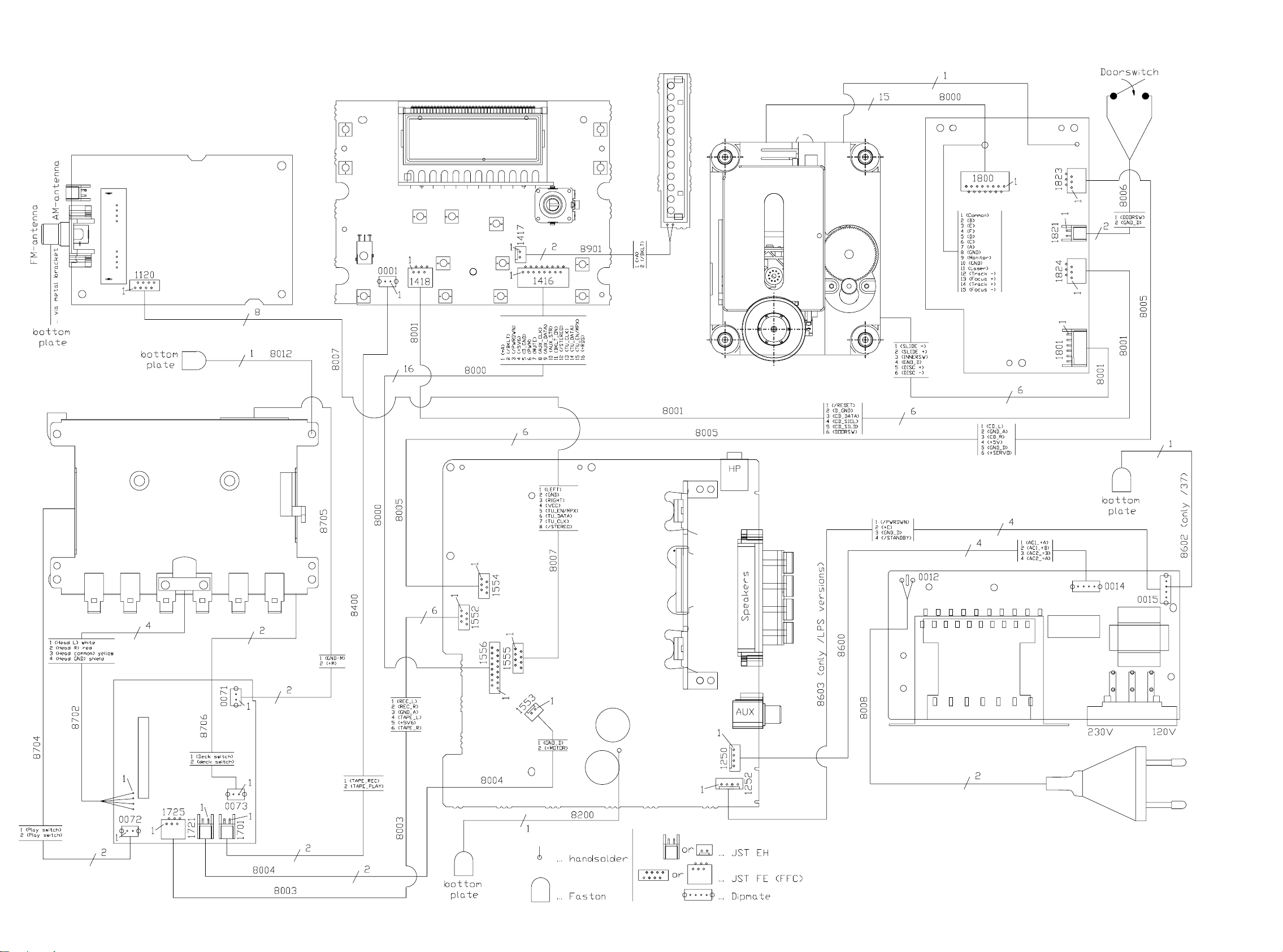
SET WIRING DIAGRAM
ECO6 Tuner Board
Front Board
LED
Board
CD Drive
CD99 DA11
CD99 DA11
ECO-MTF Deck Mechanism
Recorder Board
ECO-MTF /SD
Combi
Board
Power Board
6 - 16 - 1
CIRCUIT DIAGRAM - LED BOARD LAYOUT DIAGRAM - LED BOARD
3901 C1
3902 C2
3903 C3
3904 C3
6901 A1
6902 B1
A
8901A
6903 B1
6904 A2
6905 B2
6906 B2
6907 A2
6908 B2
6909 B2
6910 A3
6911 B3
6912 B3
8901A B1
8901B B1
123
6901
LTL-16KGE
6902 6911
LTL-16KGE
6904
LTL-16KGE
6905
LTL-16KGE
6907
LTL-16KGE
6908
LTL-16KGE
6910
LTL-16KGE
LTL-16KGE
A
A
B
C
D
1
2
A
B
C
D
B
C
To Front Board
8901B
123
6903
LTL-16KGE
3901
120R
6906
LTL-16KGE
3902
120R
6909
LTL-16KGE
3903
120R
6912
LTL-16KGE
3904
120R
B
C
E
F
G
E
F
G
12
7 - 1 7 - 1
CIRCUIT DIAGRAM - FRONT BOARD
0001 F15
1406 I8
1400 I11
1407 I8
1408 I7
1401 I10
1409 I6
1402 I10
1410 I6
1403 I9
1411 I6
1404 I9
1412 I5
1405 I8
1 12
FRONT BOARD
DISPLAY CONNECTION TABLE
COM0
Pin
1
A
B
C
D
E
F
G
H
I
1e
1m
2
3
1d
4
1c
5
2e
6
2m
72l
2d
2c
8
3e9
3m
10
3d 3l
11
3c12
4e
13
14
4m
4d
15
16
5e
17
5m
18
5d
19
20
5c
6e
21
22
6m
23
6d
24
6c
25
7e
26
7m
27
7d
7c
28
29
8e
8m
30
8d
31
8c
32
AM
33
--
34
--
35
36
--
COM0
37
+RDS
3444
100R
2424
100n
3445
2K2
5404
AT-51
4M332
33p
2425
4.5V
3446
2426
1413 I5
1414 I4
1415 I12
1416 B15
1417 D15
1418 E15
1420 G15
COM1
1g
1i
1l
1k
2g
2i
2k
3g
3i
3k
4g
4i
4l
5g
5i
5l
5k
6g
6i
6l
6k
7g
7i
7l
7k
8g
8i
8l
8k
LW STEREO
--
--
COM1
--
+C
9400
foreseen
12
VDDD
OSCO
14
220K
OSCI
13
22p
1425 A5
2400 B11
2401 B11
2402 B9
2403 B10
2404 C11
2405 C11
COM2
ROCK
1f
POP
1h
1j
1a
1b
JAZZ
I.S.
2f
2h
DBB
2a
2j
NEWS
2b
3f
EON
3h
RDS
3j
3a
SIDE B
3b
4f
SIDE A
4h
Y3
4a
4j
4b4k4c
Y1
Y2
5f
RECORD
5h
5j
5a
5b
PROGRAM
CD
6f
REPEAT
6h
6a
6j
SHUFFLE
6b
TIMER
7f
ALL
7h
7a
7j
7b
DOT
COLON
8f
FM
8h
8j
8a
MW
8b
TUNER
--
COM3
COM2
--
--
--
--
--
7406
SAA6579T
1
QUAL
BIT
QUALITY
GENERATOR
AND
DIVIDER
OSCILLATOR
FILTER
RECONSTRUCTION
57 Khz
BANDPASS
(8th ORDER)
ANTI-
FILTER
ALIASING
MUX
SCOUT
8
4
2406 E5
2407 F5
2408 F4
2409 F4
2410 F5
2411 F5
2412 F6
COM3
f
h
g
m
e
RDS DECODER
16
2
RDCL
RDDA
DECODER
DIFFERENTIAL
BIPHASE
SYMBOL
DECODER
FIXED DIVIDER
VARIABLE AND
COSTAS LOOP
VP1
CLOCKED
COMPARATOR
VDDA
CIN
5
3
7
2427
560p
2420 I11
2413 F6
2421 I7
2414 G6
2422 I12
2415 F6
2423 I12
2416 F6
2424 F1
2417 H4
2418 H5
2425 G1
2419 H9
2426 G1
3
a
i
b
j
k
l
c
d
i
PIN 55 to 63 2.8V
PIN 68 to 95 2.8V
3442 33K
3443 33K
15
T57
11
VSSD
TEST
10
SELECTOR SWITCH
MODE
9
TEST LOGIC AND OUTPUT
CLOCK
AND SYNC
REGENERATION
6
VSSA
VOLTAGE
REFERENCE
VREF
2428
2u2
2429 330p
321
3480 F14
2427 I2
2428 I3
2429 I3
2430 A14
2431 B12
2432 B13
2433 B13
22K
3499
T445
T446
T447
2434 B13
2435 D12
2436 D12
2437 D13
2438 D13
2439 D13
2440 D13
42
+uP
+uP
0V
3406
100K
RDS_DATA
+5V6
5.3V
T453
3405
1K
2408
100n
2409
10n
RDS_CLK
RDS_MPX
3410
100R
2417
47u
2441 D13
2442 F12
2443 F13
2444 F13
2445 F13
2446 F13
2447 G12
1425
LP-6404
LCD(1:50)
3403
6K8
RESET
3407
1K
7402
BC847B
IR RECEIVER
7404
TSOP2836
2
SUP
V
OUT
GND
34
3436
5K6
1414
2448 G13
2449 H13
2450 H13
2451 H13
3400 A11
3401 A10
3402 C11
0.96V
3404
1K8
+uP
2410
10n
1
3435
3K3
1413
54
3403 E5
3404 E5
3405 F4
3406 F4
3407 F5
3408 G6
3409 F7
To uP pin no.95
81
82
83
84
85
86
87
88
89
90
91
92
93
94
95
96
97
2406
10n
98
99
100
2407
100n
5402
2411
15p
OSC
RC5
T448
3412
10K
3411
100K
3434
2K2
*
3410 H4
3417 H10
3411 H5
3418 D11
3412 H5
3419 D11
3413 F7
3420 I11
3414 F9
3421 I11
3415 H8
3422 I11
3416 H9
3423 I10
80
SEG10
SEG11
SEG9
SEG12|P9379SEG13|P9278SEG14|P9177SEG15|P9076SEG16|P6775SEG17|P6674SEG18|P6573SEG19|P64
SEG8
SEG7
SEG6
SEG5
SEG4
SEG3
SEG2
SEG1
SEG0
COM3
COM2
COM1
COM0
VLC
NC1
NC2
NC3
VDD1
VSS1
XIN
XOUT2XOUT|P22
RESET_
1
3
4
2V
1.7V
4.5V
2.4V
T443
8MHz
2412 15p
3408
470K
4.3V
T444
2415
27p
2413 68p
Communication
5403
32K768
7403
BC847B
4V
2418
0V
1n
KEY GROUP1
3432
3433
1K
1K5
14101411
6
1
2526272829 33031323334353637 4510111213141516171819 22021222324
XIN|P21
6
5
2V
2416
FREQ_SHIFT
2414
10n
3424 I10
3425 I9
3426 I9
3427 I8
3428 I8
3429 I7
3430 I7
2
TEST
INTS_|STOP_|P20
7
8
2.2V
27p
3413
RDS_CLK
3431
470R
1409
3431 I7
3432 I6
3433 I6
3434 I5
3435 I5
3436 I5
3437 I12
4
3
72
SEG20|P6371SEG21|P6270SEG22|P6169SEG23|P60
7400
TMP87CM23F
PWM|P41
SCK1|P4211SCK2|P45
INT3|TCIP40
10
9
2.3V
4.7V
0V
1K
10K
3440
3409
1K
2K7
3441
3470
RDS_DATA
ROTARY2
PWM
+Keys
3429
10K
3430
5K6
3445 G1
3438 I12
3446 G1
3439 F9
3447 A14
3440 F7
3448 A14
3441 F7
3449 A14
3442 E3
3443 F3
3450 F8
3444 F1
3451 A13
6
5
S11|P4312S12|P46
7
6789
SEG24|P7767SEG25|P7666SEG26|P7565SEG27|P7464SEG28|P7363SEG29|P72
SO1|P4413SO2|P47
16
15
14
0V
0/4.7V
+C
3450
10K
3497
1K
10K
3498
TU_EN
KEYS_AD2
EEPROM_CLK
KEY GROUP2
3428
2421
10K
1407
10n
3452 A13
3459 C13
3460 F8
3453 E11
3461 C14
3454 A14
3462 F9
3455 F8
3463 C13
3456 B13
3457 A13
3464 F9
3458 F8
3465 C14
8
1
To uP pin no.55
62
SEG30|P7161SEG31|P7060SEG32|P8759SEG33|P8658SEG34|P8557SEG35|P8456SEG36|P8355SEG37|P8254SEG38|P81
P0017P0118P0219P0320P0421P0522P0623P07
0V
0V0V0V0V5V
4.5V
0.8/4.6V
1K
10K
3455
TU_CLK
3458
1K
3460
STEREO
BKLT_ON
4K7
3462
3464
470R
AUX_STR
AUX_DATA
3466
4K7
AUX_CLK
+C
3416
220R
2419
100n
4400
4.7V
foreseen
3415
15K
4401
3426
3427
3K3
5K6
14051412
1406
24
4K7
3468
MUTE
3466 F9
3467 C13
3468 F9
3469 C14
3470 F7
3471 D14
3472 D13
INT0|P1025INT1|P11
4.2V
4K7
3473
2K2
3414
PWRDWN
RC5
7405
ST24C01B6
1
E0
2
E1
3
E2
6
SCL
7
MODE|WC_
3425
2K2
1404
INT2|TC1|P12
27
26
4.7V
1K
3439
33K
ROTARY1
VCC
EEPROM
1403
3473 F9
3474 E14
3475 D11
3476 E14
3477 E11
3478 E14
3479 E11
T452
2402
100u
53
DV0|P13
28
T449
8
SDA
VSS
4
3424
1K5
+uP
4.6V
52
5168
VDD2
VSS2
VASS
SEG39|P80
VAREF
AIN7|P57
AIN6|P56
AIN5|P55
AIN4|P54
AIN3|P53
AIN2|P52
AIN1|P51
AIN0|P50
TC2|P15
PPG|P14
30
29
5
14021408
3481 E11
3482 F14
3483 E13
3484 E11
3485 F14
3486 D11
5400
1u5
P36
P35
P34
P33
P32
P31
P30
P17
P16
3417
15K
3423
1K
T451
3401
15R
2403
100n
50
49
4.5V
48
47
46
4.5V
4.5V
45
0V
44
0V
43
0V
42
0V
41
0V
40
4.7V
39
4.7V
38
0V
37
0V
36
0V
35
0V
34
0V
33
0/4.7V
32
31
EEPROM_DATA
3422
470R
1401
3487 G14
3488 D11
3489 G14
3490 C11
3491 G13
3492 D11
3493 G14
+C
4.7V
2401
10n
3492
1K
3486
100R
3418
1K5
3475
330R
3479
470R
3453
1K
+Keys
3400
2405
10n
10R
5401
3420
10K
1400
1u5
3490
3494
3488
100R
3419
3477
470R
3481
470R
3484
3421
3494 D11
3495 G13
3496 G13
3497 F8
3498 G8
3499 G3
4400 H9
111098765
+5_ETF
9401
foreseen
4.8V
+Keys
1K
1K
1K5
10K
5K6
1110987
4401 I9
5400 A10
5401 C11
5402 F5
5403 F6
5404 G1
6400 A11
+5V6
+RDS
4.8V
T441
5.6V
6400
1N4148
2400
10n
4.5V
T442
+uP
3402
100R
2404
100u
KEYS_AD2
KEYS_AD1
TA_SH_CLK
TA_SH_DATA
TA_SH_STR
TA_ADC2
TA_ADC1
EEPROM_CLK
EEPROM_DATA
CD_RESET
CD_DATA
CD_SICL
CD_SILD
TU_DATA
DOORSW
ROTARY1
KEYS_AD1
2420
10n
9400 F1
9401 A11
T401 B14
T402 B14
T403 B14
T404 B14
T405 C14
T406 C14
T407 C14
T408 C14
T409 C14
T410 C14
T411 C14
T412 D14
+C
3452
10K
T413 D14
T414 D14
T421 E14
T422 E14
T423 E14
T424 F14
T425 F14
+C
3457
10K
T426 F14
T431 G14
T432 G14
T433 G14
T434 G14
T435 G14
T436 H14
6401 B14
7400 D8
7402 F5
7403 G6
7404 H5
7405 H9
7406 F2 T447 G4
RDS_MPX
TU_EN
TU_DATA
TU_CLK
STEREO
3451
470R
3456
1K
2432
2433
BKLT_ON
AUX_STR
AUX_DATA
AUX_CLK
MUTE
PWM
PWRDWN
2431
4n7
100p
470p
2434
100p
3459
220R
3463
4K7
3467
2K2
3471
33K
470p2437
2438 470p
2439 470p
2n2
2440
470K3472
2441 10n
470p2435
2436 470p
+C
3483
CD_RESET
15K
CD_DATA
CD_SICL
CD_SILD
DOORSW
3478
470R
3482
1K
2442
220p
2443
220p
220p
220p
2446
10n
3485
*
2K2
2445
2444
TA_ADC2
*
3496
56K
*
+5_ETF
3487
2K2
TA_ADC1
*
2447
470p
*
2448
470p
*
3495
56K
TA_SH_CLK
ROTARY2
TA_SH_DATA
TA_SH_STR
2449
470p
2450
470p
2451
470p
3491
1K
ROTARY ENCODER
+C
1415
3438
3437
22K
2422
100p
22K
2423
100p
EC16
2
3
1
5
4
DC VOLTAGES MEASURED IN TUNER MODE
UNLESS OTHERWISE STATED
(230V MAINS SUPPLY)
1312
3489
3493
1K
1K
3448
1K5
3449
22K
3454
1K
3461
4K7
3465
4K7
3469
470R
+5V6
3474
1K
3476
470R
3480
1K
T441 A11
T442 B11
T443 F6
T444 F6
T445 G4
T446 G4
2430
1n
+RDS
T401
T402
T403
T404
T405
T406
T407
T408
T409
T410
T411
T412
T413
T414
T421
T422
T423
T424
T425
T426
T431
T432
T433
T434
T435
T436
T448 H5
T449 H10
T451 A10
T452 A10
T453 H4
3447
10K
6401
1N4148
16
15
14
13
12
11
10
9
8
7
6
5
4
3
2
1
12.5V
2
4V
1
1418 FE-ST-VK-N
1
2
3
4
5
6
0001 DIPMATE
1
2
1420 FE-ST-VK-N
1
2
3
4
5
6
7
151413
FE-ST-VK-N1416
+RDS
TU_EN / MPX
TU_DATA
TU_CLK
/STEREO
BKLT_ON
AUX_STR
AUX_DATA
AUX_CLK
MUTE
PWM
D_GND
+5V6
/PWRDWN
/BKLT
+A
EH-B1417
+A
/BKLT
/RESET
D_GND
CD_DATA
CD_SICL
CD_SILD
DOORSW
TAPE_REC
TAPE_PLAY
TA_ADC2
TA_ADC1
+5V
D_GND
TA_SH_CLK
TA_SH_DATA
TA_SH_STR
1514
A
B
C
To / From COMBI BOARD
D
To Backlight-Board
E
To CD99
F
To MTF
G
To TAPE
H
I
*
MODEL
MC-1xx
MC-200
ITEM
1412
2447
470p
2448
470p
3485
2K2
3K9
3487
2K2
3K9
3495
56K
3496
56K
150K
7 - 27 - 2
LAYOUT DIAGRAM - FRONT BOARD
A
B
C
D
E
F
G
H
1
2345678910111213
A
B
C
D
E
F
G
H
A
B
C
D
E
F
G
H
12345678910111213
A
B
C
D
E
F
G
H
I
J
12345678910111213
I
J
I
J
I
J
12345678910111213
 Loading...