

Page 1
EN User manual 3
SP Manual de utilizador 1 0
MANT901
FR
Manuel d'utilisateur 1 8
1
Page 2

EN
Contents
3 Safety Instructions
5 Included with Antenna
5 Mounting Antenna
6 Connecting to your TV
7 Warranty
8 Technical Support
2
Page 3
Safety Instructions
Antenna grounding and safety warn-
EN
Warning Installation of this
product near power lines is
dangerous. For your safety,
keep ladder and antenna away
from power lines. Contact may
ing
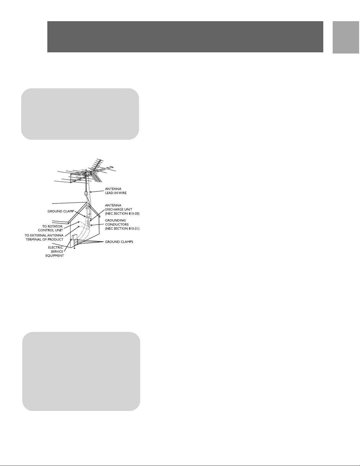
1. Outdoor antennas and lead-in conductors from antenna
to a building, should not cross over open conductors of
electric light or power circuits. They should be kept
away from all circuits to avoid the possibility of acciden tal contact.
2. Each conductor of a lead-in from an outdoor antenna should be connected with an antenna discharge unit.
Antenna discharge units (or Lightning Arrestor) should
be located outside the building or inside the building
between the point of entrance of the lead-in and the
TV, and as near as practical to the entrance of the con ductors to the building.
Important Safety Notes
NEC - National Electrical Cod e
* Antenna Discharge Unit is not
required if lead in conductors are
enclosed in a continuous metallic
shield that is permanently and
IMPORTANT
READ
BEFORE INSTAL-
LATION
If you do not feel comfortable or competent to install this
antenna we recommend that you seek the assistance of a
qualified professional antenna installer.
Read the instructions for this device thoroughly before
attempting installation.
The installation or dismantling of any antenna near power
lines is dangerous. Each year hundreds of people are killed
or injured while attempting to install or service antennas.
For your safety and proper antenna installation, read and
follow all safety precautions.
Choose an installation site for safety as well as perform ance.
All electric power lines, cable lines and telephone lines look
alike. To be safe, assume ANY overhead line can kill you.
Do not place an antenna where it could potentially fall on
to, or blow into a power line. If in doubt call your electric
provider. Let them review your site.
Outdoor antennas should be grounded with an approved
3
Page 4
EN
Safety Instructions
IMPORTANT
lighting arresting device. Local codes may apply. Use 8 AWG
or larger ground wire.
Height or other restrictions on antennas may apply to your
installation depending on your proximity to an airport, or
local ordinances.
Take the time to plan your installation procedure. Do all
assembly work on the antenna on the ground. Raise the
completed antenna after assembly.
Do NOT work on a wet, snowy or windy day or if a thunderstorm is approaching. Do NOT use a metal ladder.
If the antenna assembly starts to fall, get away from it and
let it fall. Remember that the antenna mast and cable are
all excellent conductors of electrical current.
READ
BEFORE INSTAL-
LATION
Do NOT install the antenna by yourself. Be sure that there
are two other people available for help.
If any part of the antenna should come in contact with a
power line . . . DON'T TOUCH IT OR TRY TO REMOVE IT
YOURSELF. Call your local power company immediately.
They will remove it.
Should an electrical accident occur . . . DON'T TOUCH THE
PERSON IN CONTACT WITH THE POWER LINE, or you too
can become electrocuted. Instead, use a DRY board, stick,
or rope to push or pull the victim away from the power
lines and antenna. Once clear, check the victim. If he has
stopped breathing, immediately administer cardiopul monary resuscitation (CPR) and stay with him. Have someone else call for medical help.
Install wire antennas high enough that they will not be
"walked into" by people.
Do not install antenna wire(s) over or under utility lines.
4
Page 5
Included with
Note: For final installation
and connection of your
antenna, additional hardware
may be required. Before
starting assembly, please
read through the instructions
carefully to determine your
EN
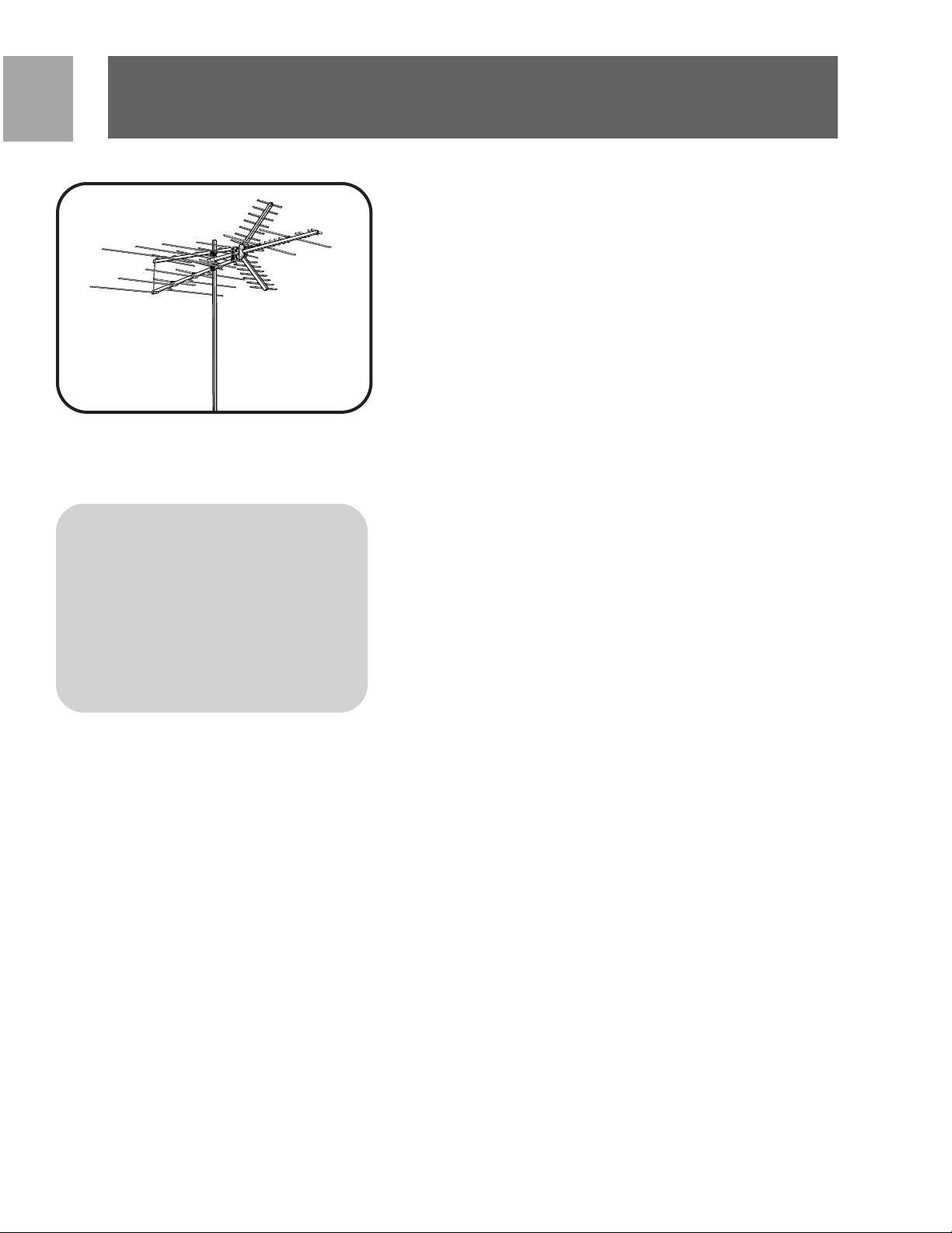
Parts included:
a. U H F B o o m - A . . . . . . . . . . . . 2
b. U H F B o o m - B . . . . . . . . . . . . 2
c. VHF Boom-A . . . . . . . . . . . . 1
d. V H F B o o m - B . . . . . . . . . . . . 2
e. Reflector Elements . . . . . . . 2
f. 46˝ Element . . . . . . . . . . . . 2
g. 50˝ Element . . . . . . . . . . . . 2
h. T u b i n g B r a c e . . . . . . . . . . . . 2
j. Phasing Wire . . . . . . . . . . . . 2
k. Reflector Brackets . . . . . . . . 2
l. Pivot Brackets . . . . . . . . . 4
n. Locking Brackets . . . . . . . . . 4
p. End Caps . . . . . . . . . . . . . . . 8
q. Screws (1-3/4˝) . . . . . . . . . 5
r. Screws (1-1/2˝) . . . . . . . . 1 0
s. Screws (3/4˝) . . . . . . . . . . 2
t. Lock Washers/ Washers . 6, 4
u. W i n g - N u t s . . . . . . . . . . . . . 1 7
v. N u t s . . . . . . . . . . . . . . . . . . 6
w.
Assembly
Band Separator . . . . . . . . . . . . 1
x. U-Bolt . . . . . . . . . . . . . . . . . 3
y. Cross Piece (for U-Bolt Assembly) 3
z. Antenna Saddle . . . . . . . . . . 1
*Quantities listed include those which may already be attached to
antenna
NOTE: Cable, mast and mounting brackets are not included.
5
Page 6
EN
Assembly
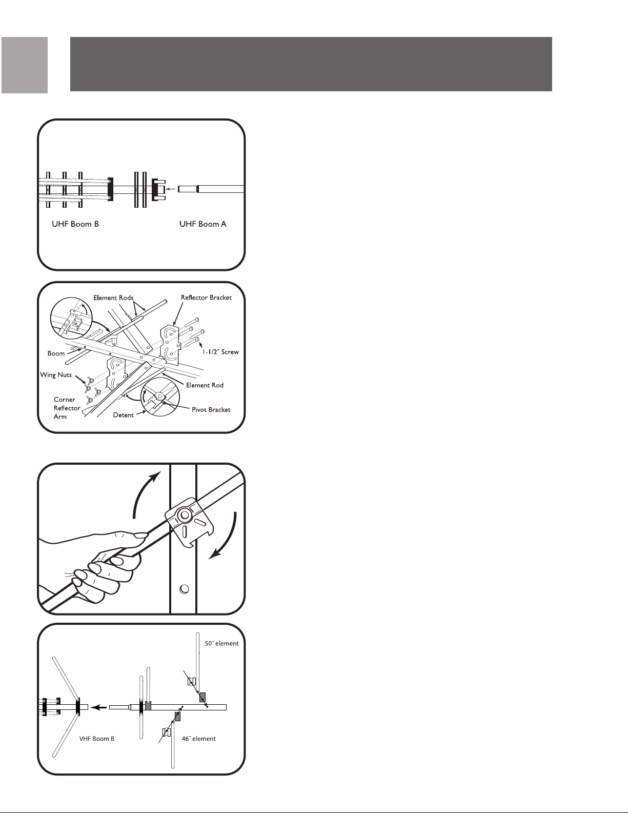
Assembly of UHF Portion
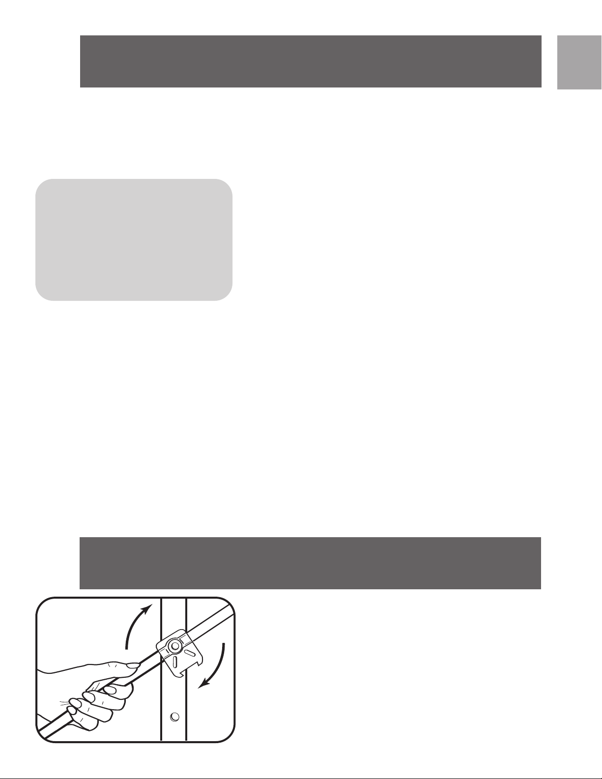
• Rotate reflector element rods into place. NOTE:
When rotating element rods, grasp close to pivot
and relieve spring pressure on pivot bracket
detents. Don’t apply excess pressure to reflector
element rods.
• Insert UHF Boom-A into UHF Boom-B and secure
using
1-1/2˝ screw and lock washer.
• Attach Reflector Arm Mounting Brackets to assem-
bled UHF Boom (previous step) using two 1-1/2˝
screws and wing-nuts. Ensure that rotation arcs in
Reflector Arm Mounting Brackets face toward UHF
Boom elements.
• Attach Corner Reflector Arms to Reflector Arm
Mounting Brackets by sliding Reflector Arms
between Mounting Brackets. Secure with 1-1/2˝
screw and wing-nuts. To fully secure Reflector
Arms, snap into locking tabs and tighten screws.
Assembly of VHF Portion
• Rotate reflector element rods on VHF Boom-A and
VHF Boom-B into place. NOTE: When rotating element rods, grasp close to pivot and relieve spring
pressure on pivot bracket detents. Don’t apply
6
excess pressure to reflector element rods.
Page 7
Assembly
• Attach one 46˝ Element to hole A in VHF Boom-B.
• Attach one 50˝ Element to VHF Boom-B.
Repeat each steps with second boom for VHF Boom-B.
EN
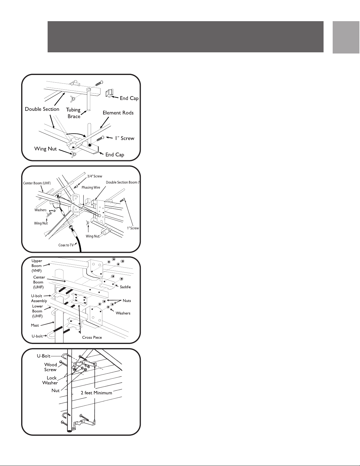
• Insert VHF Boom-B into VHF Boom-A and secure
using 1-1/2˝ screw and lock washers. Repeat steps
for 2nd boom as well.
• Attach tubing brace to rear of VHF Boom with 1-
1/2˝ screws and wing-nuts.
• Slide UHF Boom through center slot of VHF Boom
support block until hole A of UHF Boom aligns with
hole B of VHF Boom. Secure with 1-1/2˝ screw
and wing-nut.
• Attach phasing wire and lead-in wire to UHF antenna
using 3/4˝ screws, washers, and wing-nuts.
• Insert end caps at ends of all booms.
Mast Assembly (Mast not included)
• Assemble U-bolts to cross pieces.
• Use saddle on center of boom.
7
Page 8
EN
Wall
To Signal
Splitter
Drip
Loop
Assembly
• Assemble U-bolt assemblies loosely to antenna.
• Insert mast through U-bolts.
• Tighten U-bolts securely. All U-bolts should be on
one side
of mast.
• Attach mast standoff to mast.
• Insert wire in standoff and tighten with pliers.
• Power lines should be as far away as possible.
• Assemble U-bolts in wall mounts with lock washers
and nuts.
• Secure mounts to wall with wood screws.
• Separate mounts by at least two feet.
• Insert mast with assembled antenna through both
U-bolts.
• Face antenna toward TV station.
• Tighten U-bolts securely.
• Wall mounts and chimney mounts are not included.
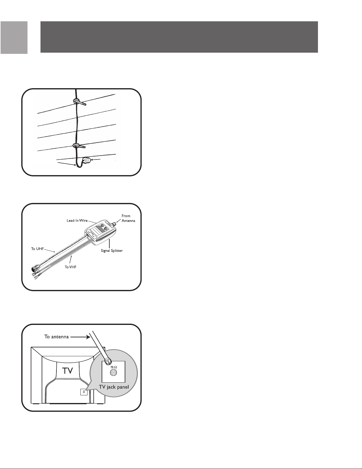
Lead-In Wire
• Attach lead-in wire to house with screw-type stand-
offs.
• Tighten standoffs with pliers after wire is installed.
• Avoid sharp bends in lead-in wire.
• Form drip loop where wire enters wall.
• Wall mounts not included.
• Mounts, mast and standoffs are not included.
Band Separator
• Attach band separator to appropriate terminals on
TV set.
• Attach antenna lead-in wire to band separator.
• An FM set or second TV set may be attached to sec-
ond output of band separator.
8
Page 9

Warranty
NOTE: Band separator is only required for older TV sets
with separate VHF/UHF inputs. For most newer sets,
simply connect cable from antenna to ‘F’ input.
SP
Technical Support
Limited Lifetime Warranty
The manufacturer warrants that this product shall be
free from defects in material, workmanship and assembly, under normal use, in accordance with the specifica tions and warnings, for as long as you own this product.
This warranty extends only to the original purchaser of
the product, and is not transferable. Defective products,
together with the dated proof of purchase, must be
returned to the place of purchase for repair or replace ment. THERE ARE NO OTHER EXPRESS WARRANTIES.
Incidental and consequential damages are disclaimed
where permitted by law. This warranty gives you specific legal rights, and you may also have other rights which
vary from state to state.
9
Page 10

SP
Contenido
1 1 Instrucciones de seguridad
1 3 Partes incluidas:
1 3 Para ensamblar
1 7 Garantía limitada por vida
1 7 Asistencia Técnica:
10
Page 11

Instrucciones de seguri -
Conexión a tierra de la antena y adver tencia de seguridad
ADVERTENCIA LA
INSTALACIÓN DE ESTE PRODUCTO CERCA DE LÍNEAS
DE ENERGÍA ELÉCTRICA ES
PELIGROSA. PARA SU
SEGURIDAD, MANTENGA LA
ESCALERA Y LA ANTENA
ALEJADAS DE LAS LÍNEAS
DE ENERGÍA ELÉCTRICA. EL
CONTACTO CON ELLAS
PUEDE SER CAUSA DE
1. Las antenas exteriores y los conductores de derivación
de la antena a un edificio no deben cruzarse sobre los
conductores abiertos de luz eléctrica ni sobre circuitos
de corriente. Deben mantenerse alejados de todos los
circuitos para evitar la posibilidad de un contacto acci dental.
2. Cada conductor de un derivador desde una antena
exterior debe conectarse con una unidad de descarga
de antena. Las unidades de descarga de la antena (o
interceptor de rayos) deben colocarse fuera del edificio
o dentro del edificio entre el punto de entrada del
derivador y la TV, y lo más cerca posible de la entrada
de los conductores al edificio.
SP
Código de Electricidad Nacional
- NEC
•La unidad de descarga de antena no es
necesaria si los conductores de
derivación se encuentran dentro de
una cobertura metálica continua que
está conectada a tierra correctamente
IMPORTANTE
LEER ANTES
DE LA
INSTALACIÓN
Notas de seguridad importantes
Si no se siente cómodo o piensa que no es competente
para instalar esta antena, recomendamos que solicite asistencia a un instalador de antenas profesional calificado.
Lea las instrucciones para este dispositivo cuidadosamente
antes de proceder a la instalación.
La instalación o desmontaje de cualquier antenna cerca de
líneas de corriente eléctrica es peligrosa. Cada año mueren
o resultan heridas cientos de personas al intentar instalar o
realizar el servicio de antenas. Por su seguridad y para
instalar correctamente la antena, lea y siga todas las pre cauciones de seguridad.
Para elegir el sitio de instalación, tenga en cuenta la seguri dad además del rendimiento. Todas las líneas de corriente
eléctrica, cables y líneas telefónicas se parecen. Por su
seguridad, asuma que CUALQUIER cable aéreo puede
provocarle la muerte. No coloque la antena donde exista
la posibilidad de que caiga sobre o entre en contacto con
un cable de corriente. Si tiene dudas, comuníquese con su
empresa de electricidad. Permítales que examinen el lugar.
11
Page 12

SP
Instrucciones de seguri -
Las antenas exteriores deben conectarse a tierra con un
interceptor de rayos aprobado. Pueden aplicarse los códigos locales. Usar un cable de tierra 8 AWG o mayor.
La instalación de su antena puede estar sujeta a restric ciones de altura u otras restricciones, dependiendo de su
proximidad con un aeropuerto o de las normas locales.
Tómese el tiempo necesario para planificar el procedimiento de instalación. Realice todo el trabajo de montaje de la
antena en la tierra. Levante la antena completa después
del montaje.
NO realice el trabajo un día lluvioso, ventoso o que esté
nevando, o si se está aproximando una tormenta eléctrica.
NO utilice una escalera de metal.
IMPORTANTE
LEER ANTES
DE LA
INSTALACIÓN
Si el montaje de la antena comienza a caerse, aléjese y
déjelo caer. Recuerde que el soporte vertical de la antena
y el cable son excelentes conductores de la corriente eléc trica.
NO instale la antena usted solo. Asegúrese de contar con
otras dos personas que colaboren con usted.
Si cualquier parte de la antena entra en contacto con una
línea de corriente . . . NO LA TOQUE NI INTENTE QUITARLA
USTED MISMO. Comuníquese de inmediato con la compañía
de electricidad local. Ellos se encargarán de quitarla.
Si ocurre un accidente eléctrico . . . NO TOQUE A LA PERSONA EN CONTACTO CON EL CABLE DE CORRIENTE, o
usted también puede resultar electrocutado. Use una
tabla, palo o cuerda SECOS para empujar o tirar de la vícti ma para alejarla de los cables de corriente y la antena. Una
vez que la persona esté alejada, examínela. Si ha dejado de
respirar, adminístrele de inmediato el procedimiento de
resucitación cardiopulmonar (CPR, por su sigla en inglés) y
permanezca con ella. Haga que alguien llame a la asistencia
médica.
12
Page 13

Partes incluidas: de la
Instale los cables de la antena a una altura suficiente como
para que las personas no entren en contacto con ellos al
caminar.
SP
Nota: Para la
instalación final y la
conexión de la
antena pueden
necesitarse her ramientas adicionales. Antes de
iniciar el montaje,
lea atentamente las
instrucciones para
determinar sus
requerimientos
No instale el o los cables de la antena sobre o por debajo
de las líneas de los servicios públicos.
Se incluyen las siguientes partes:
a. S o p o r t e U H F - A . . . . . . . . . . . . . . . . . . . . . . 2
b. Soporte UHF - B . . . . . . . . . . . . . . . . . . . . . . 2
c. S o p o r t e V H F - A . . . . . . . . . . . . . . . . . . . . . . 1
d. S o p o r t e V H F - B . . . . . . . . . . . . . . . . . . . . . . 2
e. Elementos de reflector . . . . . . . . . . . . . . . . . 2
f. E l e m e n t o 4 6 ” . . . . . . . . . . . . . . . . . . . . . . . . 2
g. E l e m e n t o 5 0 ” . . . . . . . . . . . . . . . . . . . . . . . . 2
h. P u n t a l d e t u b e r í a . . . . . . . . . . . . . . . . . . . . . . 2
j. Cable de ajuste de fases . . . . . . . . . . . . . . . . 2
k. Soportes del reflector . . . . . . . . . . . . . . . . . . 2
l. Soportes del pivote . . . . . . . . . . . . . . . . . . . 4
n. S o p o r t e s d e b l o q u e o . . . . . . . . . . . . . . . . . . . 4
p. T a p o n e s t e r m i n a l e s . . . . . . . . . . . . . . . . . . . . 8
q. T o r n i l l o s ( 1 - 3 / 4 ˝ ) . . . . . . . . . . . . . . . . . . . . . 5
r. T o r n i l l o s ( 1 - 1 / 2 ˝ ) . . . . . . . . . . . . . . . . . . . . 1 0
s. Tornillos (3/4˝) . . . . . . . . . . . . . . . . . . . . . . . 2
t. Arandelas de presión / Arandelas . . . . . . . 6, 4
u.
Para ensamblar
T u e r c a s d e fi j a c i ó n . . . . . . . . . . . . . . . . . . . . . . 1 7
v. T u e r c a s . . . . . . . . . . . . . . . . . . . . . . . . . . . . . . 6
w . S e p a r a d o r d e b a n d a s . . . . . . . . . . . . . . . . . . . 1
x. P e r n o e n U . . . . . . . . . . . . . . . . . . . . . . . . . . . 3
y. Cruceta (para montaje de perno en U) . . . . . 3
z. C a r r o d e a n t e n a . . . . . . . . . . . . . . . . . . . . . . . 1
* Las cantidades indicadas incluyen artículos que posiblemente ya estén
colocados en la antena.
13
Page 14

SP
Para ensamblar
NOTA: No se incluye el cable, el soporte vertical ni los soportes de mon -
aje.
t
Montaje de la parte UHF
• Rotar las varillas de elementos del reflector hasta colocarlas en su lugar. NOTA: Al rotar las varillas, colocar las cerca del pivote y liberar la presión del resorte en
los retenes de los soportes del pivote. No aplicar
demasiada presión a las varillas de elementos del reflec tor.
• Insertar el soporte UHF - A en el soporte UHF - B y ase gurarlo utilizando un tornillo de 1-1/2" y la arandela de
presión.
14
• Incorporar los soportes de montaje del brazo del reflec tor al soporte UHF armado (paso previo) usando dos
tornillos de 1-1/2” y tuercas de fijación. Asegurarse de
que los arcos de rotación de los soportes de montaje del
brazo del reflector enfrenten a los elementos del soporte
UHF.
• Incorporar los brazos en ángulo del relector a los
soportes de montaje del brazo del reflector deslizando
los brazos del reflector entre los soportes de montaje.
Asegurar ese montaje con tornillo de 1-1/2˝ y tuercas
de fijación. Para asegurar completamente los brazos del
receptor, presionar en dirección a las lengüetas de blo queo y ajustar los tornillos.
Montaje de la parte VHF
• Rotar las varillas de elementos del reflector en el soporte
VHF – A y el soporte VHF – B hasta colocarlas en su
lugar. NOTA: Al rotar las varillas, colocarlas cerca del
Page 15

Para ensamblar
pivote y liberar la presión del resorte en los retenes de
los soportes del pivote. No aplicar demasiada presión a
las varillas de elementos del reflector.
• Incorporar un elemento de 46” en el orificio A el soporte
VHF – B.
• Incorporar un elemento de 50” en el soporte VHF – B.
Repetir cada paso con el segundo soporte para el soporte
VHF – B.
SP
• Insertar el soporte VHF – B en el soporte VHF – A y ase gurarlo utilizando un tornillo de 1-1/2˝ y arandelas de
presión. Repetir los pasos para el segundo soporte.
• Incorporar el puntal de tubería al soporte VHF trasero
con tornillos de 1-1/2˝ y tuercas de fijación.
• Deslizar el soporte UHF a través de la ranura central del
bloque del soporte VHF hasta que el orificio A del
soporte UHF quede alineado con el orificio B del soporte
VHF. Asegurar con tornillo de
1-1/2˝ y tuerca de fijación.
• Incorporar el cable de ajuste de fases y el cable de
derivación en la antena UHF usando tornillos de 3/4˝,
arandelas y tuercas de fijación.
• Insertar los tapones terminales en los extremos de todos
los soportes.
Montaje del soporte vertical (no se
incluye el soporte vertical)
15
Page 16

SP
Para ensamblar
• Armar los pernos en U con las crucetas.
• Usar el carro en el centro del soporte.
• Armar las unidades de los pernos en U con la antena de
modo que queden flojas.
• Insertar el soporte vertical a través de los pernos en U.
• Ajustar los pernos en U. Todos los pernos en U deben
quedar en un lado del soporte vertical.
• Incorporar el separador del soporte vertical al soporte vertical.
• Insertar el cable en el separador y ajustar con alicate.
• Los cables de corriente deben estar lo más lejos posible.
• Armar los pernos en U en los soportes montados de pared con
arandelas de presión y tuercas.
• Asegurar los soportes montados a la pared con tornillos de
madera.
• Colocar los soportes montados con una separación de al
menos dos pies.
• Insertar el soporte vertical con la antena armada a través de los
pernos en U.
• Colocar la antena de frente hacia la estación de TV.
• Ajustar los pernos en U.
• No se incluyen soportes montados de pared ni soportes
montados de chimenea.
16
Cable de derivación
• Incorporar el cable de derivación a la casa con sepa -
radores de tipo tornillo.
• Ajustar los separadores con alicate después de que
esté instalado el cable.
• Evitar dobleces muy marcados en el cable de derivación
• Formar bucle cuando el cable penetra en la pared.
• No se incluyen los soportes montados de pared.
• No se incluyen los soportes montados, el soporte verti -
cal ni los separadores.
Separador de bandas
• Incorporar el separador de bandas a las terminales
apropiadas en el aparato de TV.
• Incorporar el cable de derivación de la antena al sepa -
rador de bandas.
Page 17

Garantía limitada de por
• Puede incorporarse un equipo de FM o un segundo apara to de TV a la segunda salida del separador de bandas.
NOTA: El separador de bandas solo es necesario para
aparatos de TV antiguos con entradas VHF/UHF separadas.
En los aparatos más nuevos, simplemente conectar el cable
de la antena en la entrada “F”.
SP
Asistencia Técnica:
Garantía limitada de por vida
El fabricante garantiza que este producto carece de defectos
de material, manufactura o armado, bajo uso normal y de
acuerdo con las especificaciones y advertencias, durante el
tiempo que éste sea de su propiedad. Esta garantía cubre únicamente al comprador original del producto y no es transferi ble. Los productos defectuosos deben ser devueltos al comercio vendedor, junto con la prueba de compra que indique la
fecha, para su reparación o reposición. NO EXISTEN OTRAS
GARANTÍAS EXPLÍCITAS. No se aceptan reclamos por daños
incidentales e indirectos, de acuerdo a lo permitido por la ley.
Esta garantía le otorga derechos legales específicos, y usted
puede tener otros derechos que pueden variar de estado a
estado.
17
Page 18

FR
Contenu
1 9 Consignes de sécurité
2 1 Inclus avec l’antenne
2 1 Pour Se réunir
2 5 Assistance technique
2 5 Garantie
18
Page 19

Consignes de sécurité
FR
Avertissement – Il est dan gereux d’installer ce produit à
proximité de lignes électriques.
Pour votre sécurité, gardez
l’échelle et l’antenne à distance
des lignes électriques. Un con tact avec ces dernières peut
CNE – Code national de l’élec tricité
• L’unité de décharge de l’an tenne n’est pas requise si le
fil de sortie des conducteurs
est protégé par une gaine
métallique continue qui est
mise à la masse adéquatement et en permanence.
IMPORTANT
LIRE AVANT
L’INSTALLATION
Mise à la terre de l’antenne et mise
en garde
1. Les antennes extérieures, et les câbles de descente qui
vont de l’antenne au bâtiment, ne doivent pas croiser les
câbles d’éclairage ou d’alimentation électrique à décou vert. Ils doivent être gardés à distance de tout circuit
d'alimentation afin de prévenir les risques de contact
accidentel.
2. Chaque câble de descente qui part d’une antenne
extérieure doit être connecté à une unité de décharge
d’antenne. Les unités de décharge d’antenne (ou
parafoudre) doivent être situées à l’extérieur du bâtiment, ou à l’intérieur de celui-ci entre le point d’entrée du
câble de descente et la TV, et aussi près que possible de
l’entrée des câbles dans le bâtiment.
Consignes de sécurité importantes
Si vous n’êtes pas à l’aise ou suffisamment qualifié pour
installer cette antenne, nous vous recommandons de faire
appel à un installateur d’antenne professionnel.
Lisez les instructions attentivement avant de procéder à
l’installation de cette antenne.
Il est dangereux d’installer ou démonter cette antenne à
proximité de lignes électriques. Chaque année, des centaines de personnes sont tuées ou blessées en tentant d’installer ou réparer des antennes. Afin d'installer l'antenne
d'une façon adéquate et sécuritaire, lisez et observez ces
consignes de sécurité attentivement.
Le choix de l’emplacement de l’antenne doit s’effectuer
aussi bien en fonction de la sécurité que de la qualité de la
réception.
Toutes les lignes – électriques, de câblodistribution et télé phoniques – se ressemblent. Par mesure de sécurité, considérez que N'IMPORTE QUELLE ligne aérienne est susceptible
19
Page 20

FR
Consignes de sécurité
d’être fatale.
Ne placez jamais une antenne à un endroit d’où elle pourrait
tomber sur ou frapper une ligne électrique. En cas de doute,
contactez votre compagnie d’électricité. Permettez-leur d’évaluer votre site.
Les antennes extérieures doivent être mises à la terre par
l'intermédiaire d’un parafoudre homologué. La réglementation locale peut avoir des exigences particulières. Utilisez un
fil de mise à la terre de calibre AWG 8 ou supérieur.
Des restrictions concernant l'élévation de l’antenne ou
d'autres critères peuvent s’appliquer à votre installation
selon la proximité d’aéroports ou certains règlements
locaux.
IMPORTANT
LIRE AVANT
L’INSTALLATION
Prenez le temps de bien planifier votre installation.
Effectuez les étapes d’assemblage au sol et ne hissez l’an tenne sur son emplacement qu’une fois ce travail prélimi naire terminé.
Ne travaillez PAS dans des conditions humides, neigeuses,
venteuses ni orageuses. N’utilisez PAS une échelle
métallique.
Si l’antenne commence à tomber, laissez faire et éloignezvous. N’oubliez pas que le mât et le câble d’antenne sont
d’excellents conducteurs d’électricité.
N’installez PAS l’antenne si vous êtes seul. Assurez-vous de
l’aide de deux autres personnes.
Dans l’éventualité où une partie quelconque de l’antenne
entrerait en contact avec une ligne électrique . . . N'Y
TOUCHEZ PAS NI NE TENTEZ DE L’ENLEVER PAR VOUSMÊME. Communiquez avec votre compagnie d’électricité
locale immédiatement. Des techniciens qualifiés viendront la
déplacer.
20
Si une électrocution survient . . . NE TOUCHEZ PAS À LA
PERSONNE EN CONTACT AVEC LA LIGNE ÉLECTRIQUE, car
vous pourriez aussi être électrocuté. Utilisez plutôt une
Page 21

Inclus avec l’antenne
FR
Remarque : De la ferrure addi tionnelle peut être requise
pour finaliser l’installation et la
connexion de votre antenne.
Avant de commencer le montage, veuillez lire attentive ment l’ensemble des instructions pour déterminer vos
Pour Se réunir
planche, bâton ou cordage SECS pour éloigner la victime de
la ligne électrique et de l’antenne. Une fois la victime en lieu
sûr, vérifiez son état. Si elle a cessé de respirer, pratiquez
immédiatement la réanimation cardio-respiratoire (RCR) et
demeurez avec elle. Demandez à quelqu’un de contacter une
assistance médicale.
Installez les antennes filaires à une hauteur telle que person ne ne risquera de s’y frapper.
N’installez pas de fil(s) d’antenne au-dessus ni en-dessous
de câbles de service public.
Pièces incluses :
a. F l è c h e U H F - A . . . . . . . . . . . . . . . . . . . 2
b. F l è c h e U H F - B . . . . . . . . . . . . . . . . . . . 2
c. F l è c h e V H F - A . . . . . . . . . . . . . . . . . . . 1
d. F l è c h e V H F - B . . . . . . . . . . . . . . . . . . . 2
e. Éléments réflecteurs . . . . . . . . . . . . . 2
f. Élément de 46 po (1,17 m) . . . . . . . . 2
g. Élément de 50 po (1,27 m) . . . . . . . . 2
h. J a m b e d e f o r c e . . . . . . . . . . . . . . . . . 2
j. Fil de mise en phase . . . . . . . . . . . . . . 2
k. Supports de réflecteur . . . . . . . . . . . . 2
l. Supports de pivot . . . . . . . . . . . . . . 4
n. Manettes de verrouillage . . . . . . . . . . 4
p. Capuchons d’extrémité . . . . . . . . . . . . 8
q. V i s ( 1 - 3 / 4 p o ) . . . . . . . . . . . . . . . . . . 5
r.
Vis
(11/2
po)
10
s. V i s ( 3 / 4 p o ) . . . . . . . . . . . . . . . . . . . 2
t. Rondelles freins/ Rondelles . . . . . . . 6, 4
u. É c r o u s à o r e i l l e s . . . . . . . . . . . . . . . . 1 7
v. É c r o u s . . . . . . . . . . . . . . . . . . . . . . . . . 6
w. Séparateur de bande . . . . . . . . . . . . . 1
x. Étrier de fixation . . . . . . . . . . . . . . . . 3
y. Pièce transversale (pour étrier de fixation) 3
z. S e l l e d ’ a n t e n n e . . . . . . . . . . . . . . . . . . 1
21
Page 22

FR
Pour Se réunir
Les quantités énumérées comprennent aussi les pièces déjà
*
fixées à l’antenne.
REMARQUE : Le câble, le mât et les ferrures de fixation ne sont
pas inclus.
Assemblage de la partie UHF
• Faire pivoter en place les tiges d’éléments
réflecteurs. REMARQUE : Pour les faire pivoter,
empoignez les tiges à proximité du pivot et libérez
la pression du ressort sur les détentes du support
de pivot. N’exercez pas de pression excessive sur
les tiges d’éléments réflecteurs.
• Insérez la flèche UHF-A dans la flèche UHF-B et fixez
à l’aide d’une vis 1-1/2 po et d’une rondelle frein.
• Fixez les supports de fixation du bras du réflecteur
sur l’assemblage de flèches UHF (étape précédente)
à l’aide de deux vis 1-1/2 po et leurs écrous à
oreilles. S’assurer que les arcs de rotation des sup ports de fixation des bras de réflecteur sont face
aux éléments de flèches UHF.
• Fixez les bras de réflecteur de coin aux supports de
fixation des bras de réflecteur en faisant glisser les
bras entre les supports. Fixez à l’aide de vis 1-1/2
po et d’écrous à oreilles. Fixez les bras de
réflecteur à fond en les enclenchant dans les pattes
de verrouillage et en serrant les vis.
22
Page 23

Pour Se réunir
Assemblage de la partie VHF
• Faire pivoter en place les tiges des éléments
réflecteurs des flèches VHF-A et VHF-B. REMARQUE
: Pour les faire pivoter, empoignez les tiges à prox imité du pivot et libérez la pression du ressort sur
les détentes du support de pivot. N’exercez pas de
pression excessive sur les tiges d’éléments
réflecteurs.
• Fixez un élément 46 po dans le trou A de la flèche
VHF-B.
• Fixez un élément 50 po à la flèche VHF-B.
Répétez chaque étape pour la flèche VHF-B.
FR
• Insérez le bras UHF-B dans le bras UHF-A et fixez à
l’aide de vis 1-1/2 po et de rondelles freins.
Répétez les étapes pour la deuxième flèche.
• Fixez la jambe de force à l’arrière de la flèche VHF
l’aide de vis 1-1/2 po et d’écrous à oreilles.
• Faites glisser la flèche UHF à travers le centre de la
fente du bloc de support de la flèche VHF jusqu’à ce
que le trou A de la flèche UHF s’aligne sur le trou B
de la flèche VHF. Fixez à l’aide de vis 1-1/2 po et
d’écrous à oreilles.
• Fixez le fil de mise en phase et le fil de descente à
23
Page 24

FR
Tableau
de connexion
de la TV
Vers l’antenne
TV
Pour Se réunir
l’antenne UHF à l’aide de vis 3/4 po, de rondelles et
d’écrous à oreilles.
• Insérez les capuchons aux extrémités de toutes les
flèches.
Assemblage de mât (mât non inclus)
• Fixez les étriers sur les pièces transversales.
• Utilisez la selle au centre de la flèche.
• Fixez sans serrer les étriers à l’antenne.
• Insérez le mât à travers les étriers.
• Serrez les étriers à fond. Tous les étriers doivent se
trouver sur un seul côté du mât.
24
• Fixer la douille à sertir au mât.
• Insérez le fil dans la douille et serrez à l’aide d’une pince.
• Les lignes électriques doivent se trouver le plus loin possi -
ble.
• Fixez les étriers sur les ferrures de fixation murales à l’aide
des rondelles freins et des écrous.
• Fixez les ferrures au mur à l’aide de vis à bois.
• Espacez les ferrures de fixation à intervalles d’au moins deux
pieds (61 cm).
• Insérez le mât avec l’antenne assemblée à travers les étri -
ers.
• Dirigez l’antenne vers la station de télévision.
• Serrez les étriers à fond.
• Les ferrures de fixation murales et de cheminée ne sont pas
comprises.
Fil de descente
• Fixez le fil de descente à la maison à l’aide d’une
douille à sertir (type vis).
• Serrez les douilles à sertir à l’aide d’une pince une
fois le fil installé.
• Évitez de courber le fil de descente abruptement.
• Formez un anneau d’écoulement à l’endroit où le fil
pénètre dans le mur.
• Ferrures de fixation murales non incluses.
• Les ferrures de fixation, le mât et les douilles à ser -
tir ne sont pas inclus.
Page 25

Assistance technique
Séparateur de bande
• Raccordez le séparateur de bande aux bornes appropriées
du téléviseur.
• Raccordez le fil de descente de l’antenne au séparateur
Garantie
bande.
• Une chaîne FM ou un second téléviseur peuvent être raccordés à la deuxième sortie du séparateur de bande.
FR
de
REMARQUE : Le séparateur de bande n’est requis que
pour les téléviseurs moins récents dotés d’entrées
VHF/UHF. Pour la plupart des téléviseurs récents, rac cordez simplement le câble de l’antenne à l’entrée « F ».
Assistance technique
Courriel : tech.support@Philips.com
25
Page 26

Notes
26
Page 27

Notes
27
Page 28

28
Specifications are subject to change without notice
Trademarks are property of Philips Accessories and Computer Peripherals
2006© Philips Accessories and Computer Peripherals, Ledgewood, NJ USA
www.philips.com
313520200602
Page 29

 Loading...