

Page 1

Premium 10501 11-07-2000
P10501a07.doc.DOC Maintenance instruction Premium 10501
PHILIPS LASER OPTICS
MAINTENANCE INSTRUCTION
PREMIUM 10501
Philips Components
Page 2

Premium 10501 11-07-2000
P10501A07.DOC draft Maintenance instruction Premium 10501
Preface
This document gives some maintenance information how to keep the CD unit in optimal condition.
Operating the CD unit under normal conditions will keep the need for maintenance to a minimum. In
case of operating the unit in more polluted environments, with e.q. dust and smoke, maintenance may
improve the proper working of the unit.
©Philips Electronics N.V. 2000
All rights reserved. Reproduction in whole or in part is prohibited without the written consent of the
copyright owner.
The information presented in this document does not form part of any quotation or contract, is believed
to be accurate and reliable and may be changed without notice. No liability will be accepted by the
publisher for any consequence of its use. Publication thereof does not convey nor imply any license
under patent- or other industrial or intellectual property rights.
Philips components 2000 Philips Electronics N.V. All rights reserved Page 2
Page 3

Premium 10501 11-07-2000
P10501A07.DOC draft Maintenance instruction Premium 10501
PHILIPS LASER OPTICS
MAINTENANCE INSTRUCTION
PREMIUM 10501
Author(s)
Phil Wu/Hector Li
Philips Components
Optical Storage
PECS Shanghai
Keywords:
High-end Audio
Jukebox
DSA
CD10
VAU1254
Premium 10501
Note:
The publisher reserve the right to change the data mentioned in this document without prior notice.
Philips components 2000 Philips Electronics N.V. All rights reserved Page 3
Page 4

Premium 10501 11-07-2000
P10501A07.DOC draft Maintenance instruction Premium 10501
Revision history
Version Date Remarks
Version 0.1 11-07-00 draft version
Philips components 2000 Philips Electronics N.V. All rights reserved Page 4
Page 5

Premium 10501 11-07-2000
P10501A07.DOC draft Maintenance instruction Premium 10501
Table of Contents
1. Introduction ...........................................................................................................................................................6
1.1 Handling of the unit.......................................................................................................................................6
1.2 Laser current measurement instruction ...................................................................................................... 7
1.3 Lens cleaning instruction.............................................................................................................................8
1.4 Cleaning and lubrication of the mechanical parts .................................................................................... 9
Philips components 2000 Philips Electronics N.V. All rights reserved Page 5
Page 6

Premium 10501 11-07-2000
P10501A07.DOC draft Maintenance instruction Premium 10501
1. Introduction
Information given in this document should be followed with care. The VAM1254 applied in this CD
unit is a mechanism consisting of delicate optical, mechanical and electrical components. During
handling of the unit excessive mechanical forces on any part should be avoided and proper ESD
measures should be taken. Maintenance may be necessary on the optical lens and mechanical parts of
the sledge, depending on the use and environment the unit is used. It is advised that in the application
where the CD unit is used, measures are taken to avoid as much as possible that dust can come to the
lens due to e.q. air flow in the cabinet.
1.1 Handling of the unit
If the CD unit is disconnected from the application, proper ESD measures should be taken to avoid
damage of the electrical components. Use ESD bags for transportation, a grounded workbench and
wrist strap (1Mohm) in case of separating the PCB from the mechanism. Especial the laser is ESD
sensitive when not connected to the PCB.
Never touch the lens with your fingers, and avoid that grease from the mechanical parts is spoiled on
the lens.
Do not move the sledge by pushing it by hand, but moving the sledge by spinning the sledge motor
worm gear with your fingers.
Philips components 2000 Philips Electronics N.V. All rights reserved Page 6
Page 7

Premium 10501 11-07-2000
P10501A07.DOC draft Maintenance instruction Premium 10501
1.2 Laser current measurement instruction
The laser current of the VAU1254 can be measured and gives an indication is the laser is damaged or
end-of-life. The following instructions describe how the laser current can be measured.
Measuring conditions:
- Ambient temperature 25 degree Celsius
- Measure after 5 minutes of play
Remark:
Laser current will increase at higher ambient temperatures!
1. Put the CD unit in play mode with a clean not scratched disc, preferably a test disc like SBC444 or
SBC444A, and play track 1.
2. Measure the DC voltage across the 4E7 safety resistor R3208 [1]
3. Put the CD unit in stop mode, (the laser is switched off now).
4. Measure the DC voltage across the 4E7 safety resistor R3208 in mode stop [2]
5. Calculate the laser current as follows
Laser current = (voltage [1] - voltage [2] ) / 4.7 ohm
The calculated value should be within 50 and 100 mA. (Nominal 75 mA)
This calculation assumes that the difference in current consumption of the pre-amplifier between play
and stop mode can be neglected, and that resistor R3208 has a nominal value of 4.7 ohm.
Remark:
This measurement method should be used only to check if the laser is still operating well within the
specified laser current. The location of resistor R3208 can be found in the component placement sheets
and is located close to the micro controller between the micro controller and the power connector.
Philips components 2000 Philips Electronics N.V. All rights reserved Page 7
Page 8
Premium 10501 11-07-2000
P10501A07.DOC draft Maintenance instruction Premium 10501
1.3 Lens cleaning instruction
The actuator lens of the unit is an optical component that is exposed to the environment. The
environmental conditions in Juke-Box applications is not comparable with normal home use. For
example, the nicotine from cigarette smoke can soil the lens. This might influence the playability of the
system enormous and cleaning of the lens can be necessary.
Before cleaning the lens, it is advised to make the surface of the lens clean by blowing clean air over it
in order to avoid that little particles make scratches on the lens.
Because the lens is made of synthetic material coated with a special anti-reflectivity layer, the cleaning
must be done with a non-aggressive cleaning fluid. We advice to use the following lens cleaner which
is available in a normal photo shop.
Advised lens cleaner: “KODAK LENS CLEANER CAT 176 71 36”
The actuator is a very precise mechanical component, which has to follow the tracks on the CD-disc
with a pitch of 1.6 um. This actuator may not be damaged in order to guarantee his full function. We
advice to clean the lens gently (don’t press too hard), with a soft and clean cotton tip moistened with
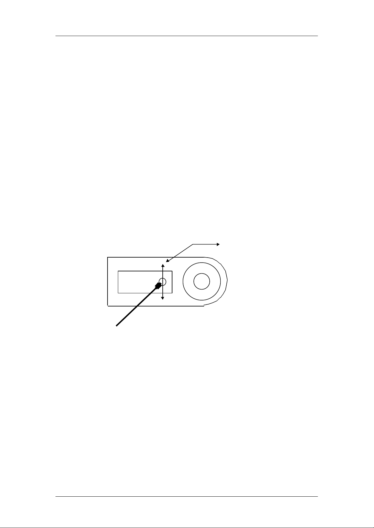
the special lens cleaner. The direction of movement of the cotton tip should be 90 degree to the radial
tracking movement of the actuator as indicated in the figure below.
Move cotton tip in this direction
Philips components 2000 Philips Electronics N.V. All rights reserved Page 8
Page 9
Premium 10501 11-07-2000
P10501A07.DOC draft Maintenance instruction Premium 10501
1.4 LUBRICATING INSTRUCTIONS CD-PRO 2
Introduction
These instructions provide some maintenance information in order to keep the CD-Pro 2 in optimal
condition. Although operating the CD-Pro-2 under normal conditions will keep the need for
maintenance to a minimum.
In case of operating the unit in more polluted environments, with e.q. dust and smoke, maintenance
may improve the proper working of the unit.
Prior to any maintenance activity the instructions should be followed with care.
Refer further to the general maintenance instructions (Chapter 7) and ESD measures
(Chapter 2 of the product specification) in this starter kit
Instructions
• Excessive greasing must be avoided in order to prevent contamination of optical parts.
• Wipe all exposed lubrication points and remove all old grease and dirt by a cotton swab.
To insure proper operation, check no cotton remains on gears and sledge guidance.
• Always move the sledge by spinning the sledge motor worm gear with finger.
To avoid damaging the gear rack and gears never move the entire sledge by hand.
1.4.1 Removal top cover.
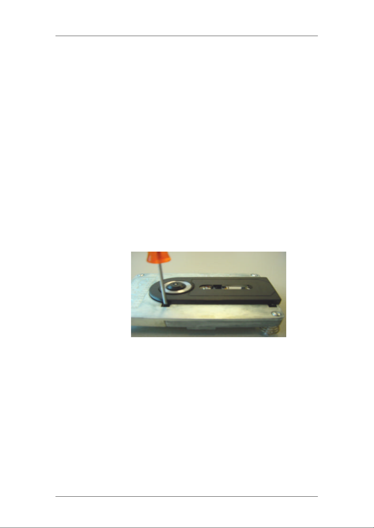
Removal of black plastic cover (4 screws)
Using a Torx screwdriver No 6.
The OPU spindle is now accessible from the topside
Figure 1
Philips components 2000 Philips Electronics N.V. All rights reserved Page 9
Page 10
Premium 10501 11-07-2000
P10501A07.DOC draft Maintenance instruction Premium 10501
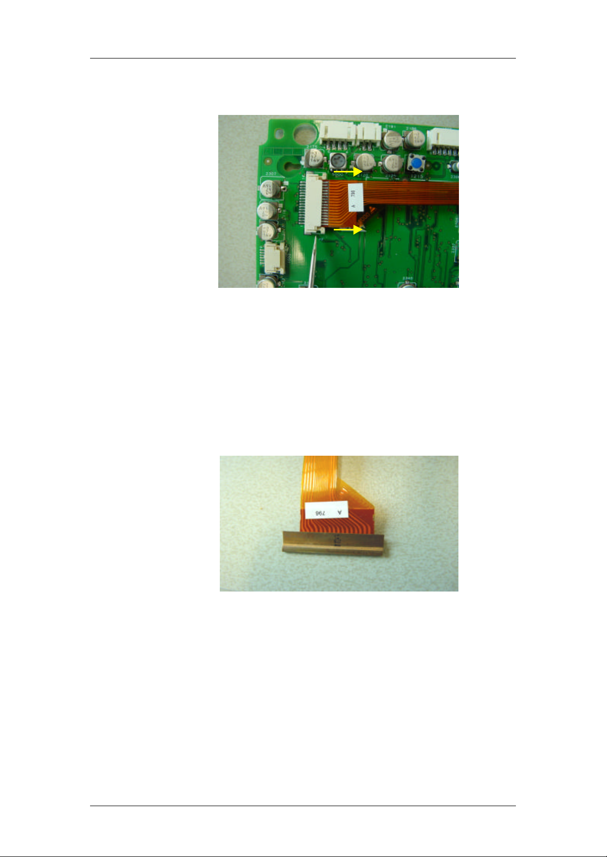
1.4.2. Removal of Pcb from the Mechanism.
Figure 2
1.4.3. E.S.D Measures
Remove the Pcb by releasing the flex foil from the connector
after unscrewing the four pcb fixing screws.
Lift the small ears on each side of the flex connectors with e.g.
a small screw driver and take out the flex foil.
Make sure during (re) mounting of the flex foil that the
flex foil is inserted straight and the connector is properly closed.
Figure 3
Take proper E.S.D. precautions when the Pcb is separated from
the mechanism.
Provide a short circuit clip or a paperclip to the leads of the
OPU flex foil in order to protect the laser and electrical circuitry
against E.S.D.
Philips components 2000 Philips Electronics N.V. All rights reserved Page 10
Page 11
Premium 10501 11-07-2000
P10501A07.DOC draft Maintenance instruction Premium 10501
1.4.4. LUBRICATION INSTRUCTIONS
1.4.4.1 LUBRICANT
• = Grease TRIBOL Molub-Alloy 9890-2
1.4.4.2 INSTRUCTIONS
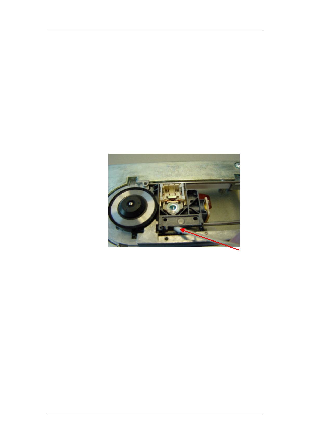
• Lubrication OPU spindle (Top side)
Figure 4
Grease
Add on the OPU spindle one dot of grease
between the two bearings holes.
It is not necessary to remove the metal cover of the CD unit.
Philips components 2000 Philips Electronics N.V. All rights reserved Page 11
Page 12
Premium 10501 11-07-2000
P10501A07.DOC draft Maintenance instruction Premium 10501
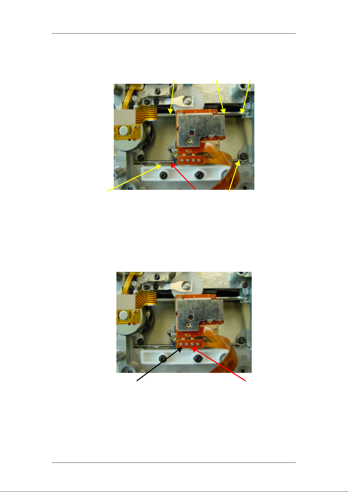
• Lubrication of OPU spindle and D2 spindle (bottom side)
Grease (OPU spindle)
(Spindle D2) Grease
Figure 5
Add on the OPU spindle and D2 spindle one dot of grease on each side
of the sledge.
• Lubrication of Actuator Spring clip
(Actuator spring clip) Grease
Figure 6
Press down the actuator sledge spring and add one drop of grease on
the spring
Philips components 2000 Philips Electronics N.V. All rights reserved Page 12
Page 13
Premium 10501 11-07-2000
3rd Bearing
P10501A07.DOC draft Maintenance instruction Premium 10501
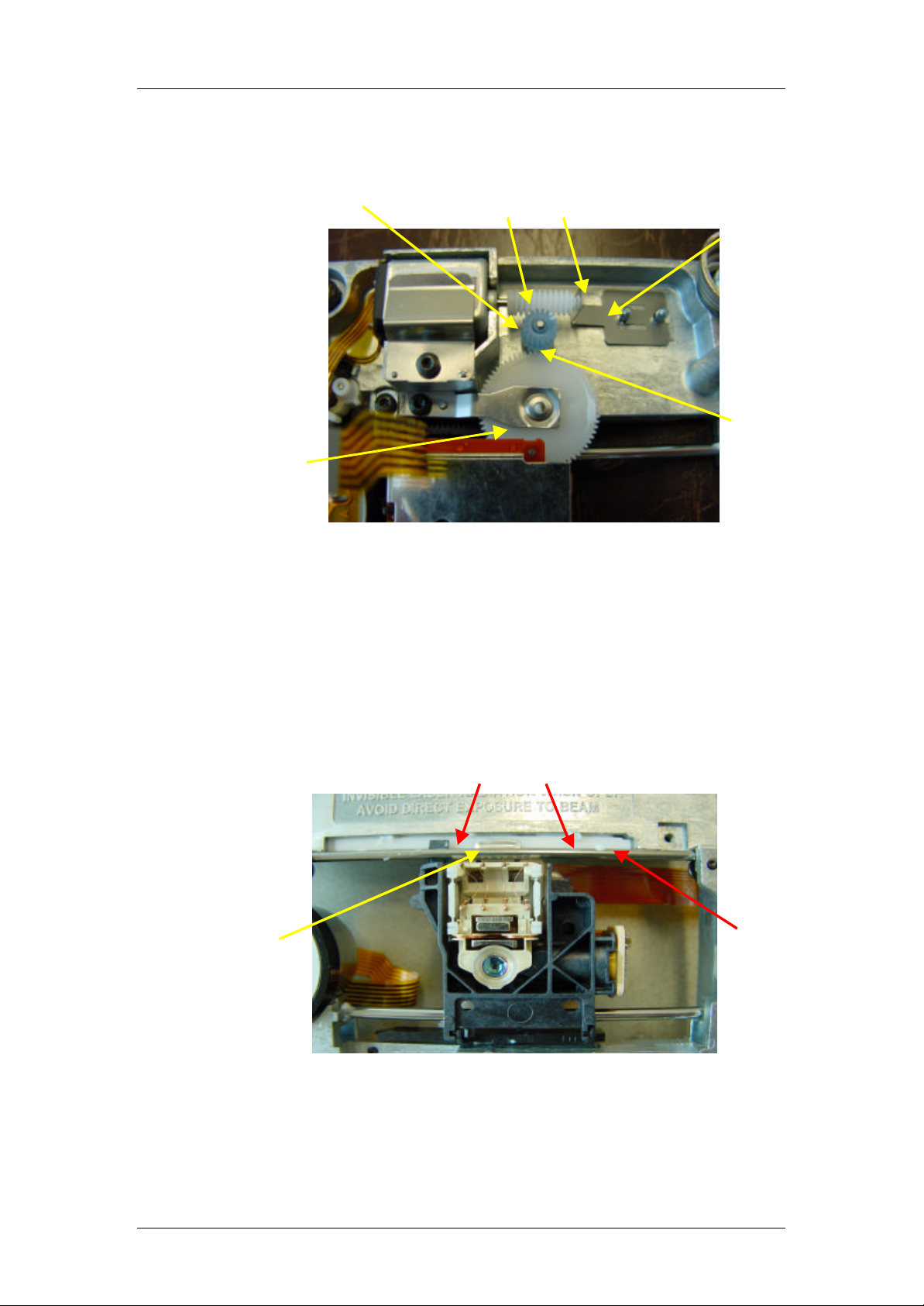
• Lubrication gearwheels
(Idler wheel)
(Gearwheel)
Grease
Figure 7
Add one dot of grease between pivot spring and worm
between worm and idler wheel - between idler wheel and
gearwheel
Excessive greasing must be avoided
(Pivot spring)
Grease
• Lubrication third bearing (Top side)
3rd bearing spring
Add 2 dots of grease on the guidance pane at each side of
the 3rd bearing spring
Grease
Figure 8
Philips components 2000 Philips Electronics N.V. All rights reserved Page 13
 Loading...