

Philips Magnetoresistive Sensor User Manual

DISCRETE SEMICONDUCTORS
General
Magnetoresistive sensors for
magnetic field measurement
2000 Sep 06

Philips Semiconductors
Magnetoresistive sensors for
magnetic field measurement
CONTENTS
General field measurement
• Operating principles
• Philips magnetoresistive sensors
• Flipping
• Effect of temperature on behaviour
• Using magnetoresistive sensors
• Further information for advanced users
• Appendix 1: The magnetoresistive effect
• Appendix 2: Sensor flipping
• Appendix 3: Sensor layout.
General
Fig.1 Philips magnetoresistive sensors.
2000 Sep 06 2
Philips Semiconductors
Magnetoresistive sensors for
magnetic field measurement
The KMZ range of magnetoresistive sensors is
characterized by high sensitivity in the detection of
magneticfields,awideoperatingtemperaturerange,alow
and stable offset and low sensitivity to mechanical stress.
They therefore provide an excellent means of measuring
both linear and angular displacement under extreme
environmental conditions, because their very high
sensitivity means that a fairlysmall movement of actuating
components in, for example, cars or machinery (gear
wheels, metal rods, cogs, cams, etc.) can create
measurable changes in magnetic field. Other applications
for magnetoresistive sensors include rotational speed
measurement and current measurement.
Examples where their properties can be put to good effect
can be found in automotive applications, such as wheel
speed sensors for ABS and motor management systems
and position sensors for chassis position, throttle and
pedal position measurement. Other examples include
instrumentation and control equipment, which often
require position sensors capable of detecting
displacements in the region of tenths of a millimetre (or
even less), and in electronic ignition systems, which must
be able to determine the angular position of an internal
combustion engine with great accuracy.
Finally, because of their high sensitivity, magnetoresistive
sensors can measure very weak magnetic fields and are
thus ideal for application in electronic compasses, earth
field correction and traffic detection.
Ifthe KMZ sensors are to be usedtomaximum advantage,
however, it is important to have a clear understanding of
their operating principles and characteristics, and how
theirbehaviourmay be affected by external influences and
by their magnetic history.
Operating principles
Magnetoresistive (MR) sensors make use of the
magnetoresistive effect, the property of a current-carrying
magnetic material to change its resistivity in the presence
of an external magnetic field (the common units used for
magnetic fields are given in Table 1).
Table 1 Common magnetic units
1 kA/m = 1.25 mTesla (in air)
1 mT = 10 Gauss
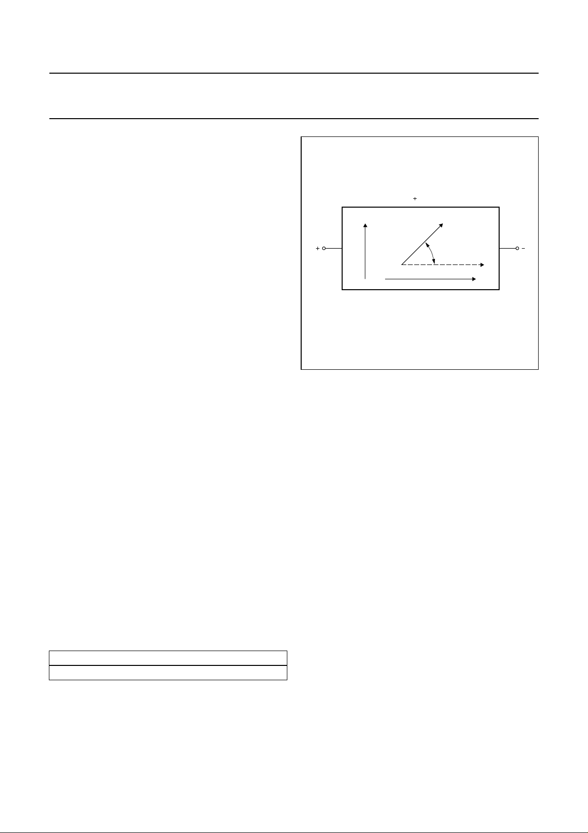
The basic operating principle of an MR sensor is shown in
Fig.2.
General
α
Current
2
I
MLC127
(1)
handbook, halfpage
H
R = R ∆ R cos α
00
Permalloy
Magnetization
Fig.2 The magnetoresistive effect in permalloy.
Figure 2 shows a strip of ferromagnetic material, called
permalloy (19%Fe, 81%Ni). Assume that, when no
external magnetic field is present, the permalloy has an
internal magnetization vector parallel to the current flow
(shown to flow through the permalloy from left to right).
If an external magnetic field H is applied, parallel to the
plane of the permalloy but perpendicular to the current
flow,the internal magnetization vector of thepermalloy will
rotate around an angle α. As a result, the resistance of R
of the permalloy will change as a function of the rotation
angle α, as given by:
RRO∆ROcos2α+=
and ∆Ro are material parameters and to achieve
R
o
optimum sensor characteristics Philips use Fe19Ni81,
which has a high Rovalue and low magnetostriction. With
this material, ∆Ro is of the order of 3%. For more
information on materials, see Appendix 1.
It is obvious from this quadratic equation, that the
resistance/magneticfieldcharacteristicisnon-linearandin
addition, each value of R is not necessarily associated
with a unique value of H (see Fig.3). For more details on
the essentials of the magnetoresistive effect, please refer
to the Section “Further information for advanced users”
laterin this chapter or Appendix 1, which examines the MR
effect in detail.
2000 Sep 06 3
Philips Semiconductors
Magnetoresistive sensors for
magnetic field measurement
handbook, halfpage
Fig.3 The resistance of the permalloy as a
function of the external field.
R
H
MLC128
General
In this basic form, the MR effect can be used effectively for
angular measurement and some rotational speed
measurements, which do not require linearization of the
sensor characteristic.
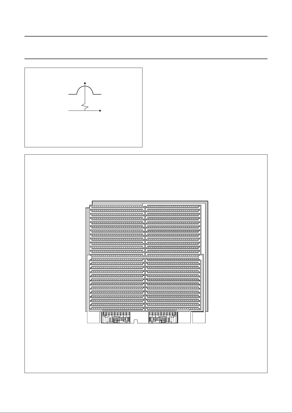
In the KMZ series of sensors, four permalloy strips are
arranged in a meander fashion on the silicon (Fig.4 shows
one example, of the pattern on a KMZ10). They are
connected in a Wheatstone bridge configuration, which
has a number of advantages:
• Reduction of temperature drift
• Doubling of the signal output
• The sensor can be aligned at the factory.
handbook, full pagewidth
MBC930
Fig.4 KMZ10 chip structure.
2000 Sep 06 4

Philips Semiconductors
Magnetoresistive sensors for
magnetic field measurement
Two further resistors, RT, are included, as shown in Fig.5.
Theseare for trimming sensor offset down to (almost)zero
during the production process.
MLC129
handbook, halfpage
R
T
V
CC
R
T
GND
2 1
V
O
34
V
O
General
Forsome applications however, the MR effect can be used
to its best advantage when the sensor output
characteristic has been linearized. These applications
include:
• Weak field measurements, such as compass
applications and traffic detection;
• Current measurement; and
• Rotational speed measurement.
For an explanation of how the characteristic is linearized,
please refer to the Section “Further information for
advanced users” later in this chapter.
Philips magnetoresistive sensors
Based on the principles described, Philips has a family of
basic magnetoresistive sensors. The main characteristics
of the KMZ sensors are given in Table 2.
Fig.5 Bridge configuration with offset trimmed to
zero, by resistors RT.
Table 2 Main characteristics of Philips sensors
SENSOR
TYPE
PACKAGE
FIELD
RANGE
(kA/m)
(1)
V
(V)
CC
SENSITIVITY
mV V⁄()
--------------------kA m⁄()
R
bridge
(kΩ)
LINEARIZE
MR
EFFECT
APPLICATION
EXAMPLES
KMZ10A SOT195 −0.5 to +0.5 ≤9 16.0 1.2 Yes compass, navigation, metal
KMZ10A1
(2)
SOT195 −0.05 to +0.05 ≤9 22.0 1.3 Yes
detection, traffic control
KMZ10B SOT195 −2.0 to +2.0 ≤12 4.0 2.1 Yes current measurement,
KMZ10C SOT195 −7.5 to +7.5 ≤10 1.5 1.4 Yes
angular and linear position,
reference mark detection,
wheel speed
KMZ51 SO8 −0.2 to +0.2 ≤8 16.0 2.0 Yes compass, navigation, metal
KMZ52 SO16 −0.2 to +0.2 ≤8 16.0 2.0 Yes
detection, traffic control
Notes
1. In air, 1 kA/m corresponds to 1.25 mT.
2. Data given for operation with switched auxiliary field.
2000 Sep 06 5

Philips Semiconductors
Magnetoresistive sensors for
magnetic field measurement
Flipping
The internal magnetization of the sensor strips has two
stable positions. So, if for any reason the sensor is
influenced by a powerful magnetic field opposing the
internal aligning field, the magnetization may flip from one
position to the other, and the strips become magnetized in
the opposite direction (from, for example, the ‘+x’ to the
‘−x’ direction). As demonstrated in Fig.6, this can lead to
drastic changes in sensor characteristics.
MLC130
handbook, halfpage
V
O
(mV)
10
0
2424
H (kA/m)
y
General
The field (e.g. ‘−Hx’) needed to flip the sensor
magnetization, and hence the characteristic, depends on
the magnitude of the transverse field ‘Hy’: the greater the
field ‘Hy’, the smaller the field ‘−Hx’. This follows naturally,
since the greater the field ‘Hy’, the closer the
magnetization's rotation approaches 90°, and hence the
easier it will be to flip it into a corresponding stable position
in the ‘−x’ direction.
Looking at the curve in Fig.7 where Hy= 0.5 kA/m, for
such a low transverse field the sensor characteristic is
stable for all positive values of Hx and a reverse field of
≈1 kA/m is required before flipping occurs. At Hy= 2 kA/m
however, the sensor will flip even at smaller values of ‘Hx’
(at approximately 0.5 kA/m).
Fig.6 Sensor characteristics.
handbook, full pagewidth
10
reversal
of sensor
characteristics
MLC131
V
O
(mV)
100
50
0
3
2
50
100
1231
H =
y
2 kA/m
0.5 kA/m
H (kA/m)
x
Fig.7 Sensor output ‘Vo’ as a function of the auxiliary field ‘Hx’ for several values of transverse field ‘Hy’.
2000 Sep 06 6

Philips Semiconductors
Magnetoresistive sensors for
magnetic field measurement
Figure 7 also shows that the flipping itself is not
instantaneous, because not all the permalloy strips flip at
thesamerate.Inaddition, it illustrates the hysteresis effect
exhibited by the sensor. For more information on sensor
flipping, see Appendix 2 of this chapter.
Effect of temperature on behaviour
Figure 8 shows that the bridge resistance increases
linearly with temperature, due to the bridge resistors’
temperature dependency (i.e. the permalloy) for a typical
KMZ10B sensor. The data sheets show also the spread in
this variation due to manufacturing tolerances and this
should be taken into account when incorporating the
sensors into practical circuits.
In addition to the bridge resistance, the sensitivity also
varies with temperature. This can be seen from Fig.9,
which plots output voltage against transverse field ‘Hy’ for
various temperatures. Figure 9 shows that sensitivity falls
with increasing temperature (actual values for given for
every sensor in the datasheets). The reason for this is
rather complex and is related to theenergy-band structure
of the permalloy strips.
General
handbook, halfpage
3
R
bridge
(kΩ)
2
1
40 160
0 40 80 120
Fig.8 Bridge resistance of a KMZ10B sensor as
a function of ambient temperature.
MBB897
T ( C)
amb
o
2000 Sep 06 7

Philips Semiconductors
Magnetoresistive sensors for
magnetic field measurement
V
O
(mV/V)
15
10
5
handbook, full pagewidth
T = 25 C
amb
o
MLC134
o
25 C
o
75 C
o
125 C
General
0
5
10
operating range
15
32
1
0
1
2
H (kA/m)
3
y
Fig.9 Output voltage ‘Vo’ as a fraction of the supply voltage of a KMZ10B sensor as a function of transversefield
‘Hy’ for several temperatures.
2000 Sep 06 8

Philips Semiconductors
Magnetoresistive sensors for
magnetic field measurement
Figure 10 is similar to Fig.9, but with the sensor powered
by a constant current supply. Figure 10 shows that, in this
case, the temperature dependency of sensitivity is
significantly reduced. This is a direct result of the increase
in bridge resistance with temperature (see Fig.8), which
V
O
(mV/V)
75
50
handbook, full pagewidth
General
partly compensates the fall in sensitivity by increasing the
voltage across the bridge and hence the output voltage.
Figure 8 demonstrates therefore the advantage of
operating with constant current.
MLC135
T = 25 C
amb
o
o
25 C
o
75 C
o
125 C
25
0
25
50
75
42
operating range
0
2
H (kA/m)
y
4
Fig.10 Output voltage ‘Vo’ of a KMZ10B sensor as a function of transverse field ‘Hy’ for several temperatures.
2000 Sep 06 9
 Loading...