

Page 1
Philips Medical Systems
SERVICE BULLETIN
Issued by
Date : 16 May 2007
Publication No. : N/A Product Group : 862020
A
PPLIES TO:
Geography
Traceable Item Identification (12NC)
and CMS Product Number
Range of Serial Numbers
Physical Main Block Number(s) (PB),
Physical Sub Block Number(s) (SB)
and System Code(s) (SC)
(Identification where the affected item
could be present)
Commercial (Sales) Product Number
T
ITLE:
SB86200577: M3000A/M3001A NIBP Pump for the MMS is available
S
ERVICE BULLETIN INFORMATION
General Information:
The repair strategy for the M3000A and M3001A has been extended. The primary strategy is still unit exchange but in
addition to the existing parts the NIBP pump can now be ordered and exchanged. Even for the M3000A the pump is
exchangeable. For consistency reasons the M3000A and M3001A are summarized as MMS.
There are some differences in the repair procedures depending on the HW revision. Please follow the below mentioned
steps to identify it. The serial number prefix and the option string defining the HW revision are labeled on the rear of the
bottom Cover. The following picture shows the label of an M3001A and the table next to it helps you determine the
Hardware revision
:
Andreas Maier; PM-B
INFORMATION ONLY — NO ACTION REQUIRED
: Worldwide
:
PMS 12NC:
989803106641
989803142101
989803142111
989803002521
N/A.
SB Ref No.
CMS (Legacy) Product Number:
M3000ATZ
M3001A_#A01TZ
M3001A_#A02TZ
M3001A_#A03TZ
:
SB86200577
PB017180-PB017078 M3001A_#A01TZ, M3001A_#A02TZ,
M3001A_#A03TZ
PB017180-PB017075 M3000ATZ
SSC=862020
PMS Product Number:
862392
862442
CMS (Legacy) Product Number:
M3000A
M3001A
Rev. A Document Number: SB86200577 Page 1 of 9
Page 2
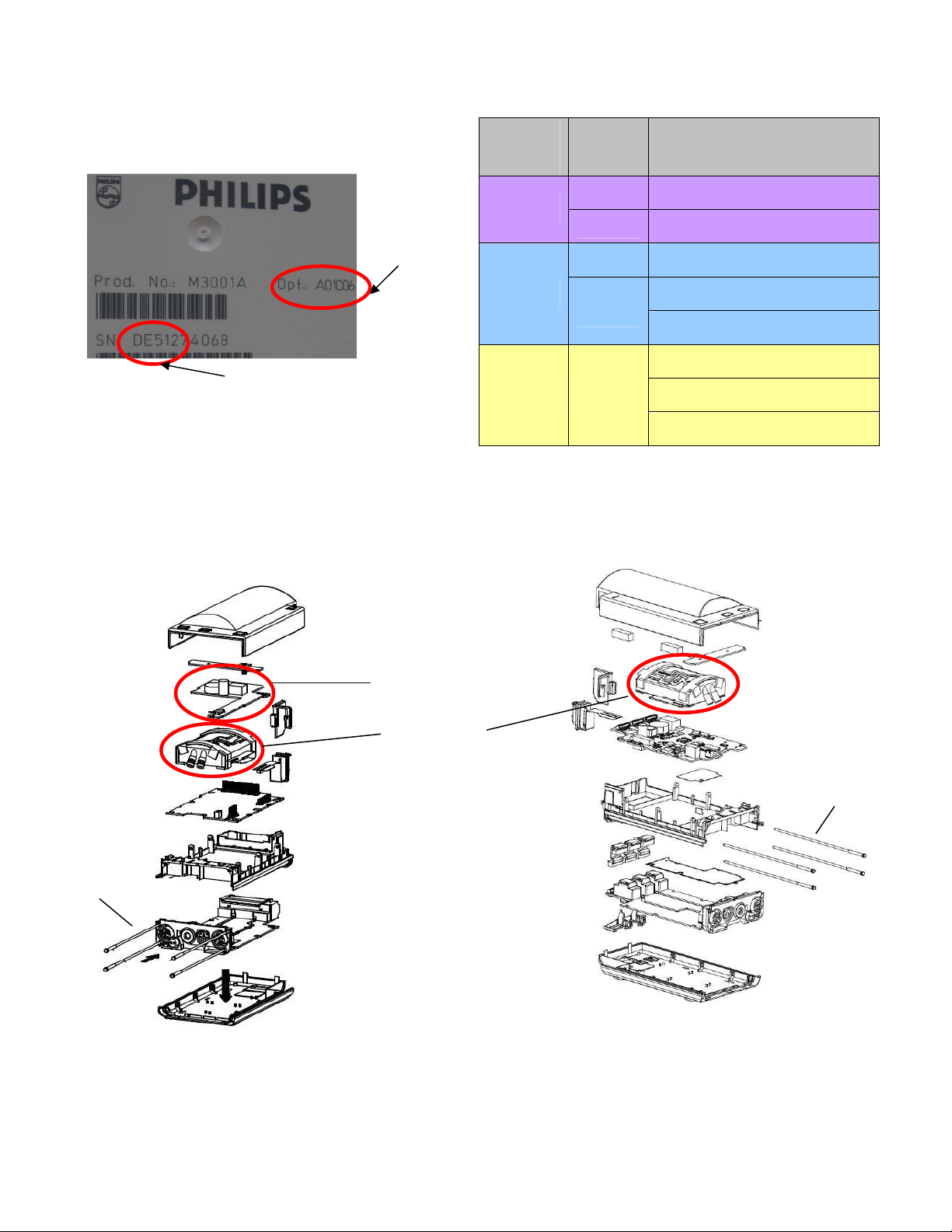
Option
Serial Number prefix
Internal Structure
M3000A and
NIBP Pump Assy
HW A
String
HW B
HW C
Picture 1
The internal structure has changed with the different HW versions. The M3000A and the M3001A HW A and HW B have
a separate DC/DC board whereas HW C has this circuit included on the main board. The most important differences
regarding the repair and the exchange are marked with red circles.
DC/DC Board (HW A/B)
Mounting Pins
Picture 2
M3001A HW A - B
DE227 --,C06,C12,C18
DE441
DE441 A02, A02C06, A02C18
DE512
DE610
DE632
DE717
A01, A01C06, A01C12, A01C18
A02, A02C06, A02C18
A01, A01C06, A01C12, A01C18
A01, A01C06, A01C18
A02, A02C06, A02C18
A03, A03C06, A03C18
Internal Structure M3001A HW C
Mounting Pins
Rev. A Document Number: SB86200577 Page 2 of 9
Page 3
Ordering information for the NBP Pump
NOTE: If the demand for this part exceeds the forecast, there might be a delay in shipment.
Description 12NC Orderable Part No
NBP Pump Assembly *)
*) The NBP Pump Assembly contains an application note on how to perform the exchange
451261020561
M3001-64500
Other Orderable MMS parts
Top Cover
Please make sure that you order the appropriate Top Cover for your MMS. Please refer to the option string as shown in
Picture 1. In addition to the option string please check the language option, whether you require English Text or Symbol
(international) version. On refurbished MMS a sticker with the Part number is placed over the option string.
Option
String
--, A01
C06, A01C06
C12,A01C12
C18,A01C18 M3001-68402/4/5 MMS Top Cover 12ld w P/T Text FAST 451261016431 M3001-68013
Empty, A01 M3001-68502/4/5
C06, A01C06 M3001-68602/4/5
C12,A01C12 M3001-68702/4/5
C18,A01C18 M3001-68802/4/5
A02 M3001-68108
A02C06 M3001-68203/8
A02C18 M3001-68403/8
A02 M3001-68503/8
A02C06 M3001-68603/8
A02C18 M3001-68803/8
A03 M3001-68107
A03C06 M3001-68207
A03C18 M3001-68407
A03 M3001-68507
A03C06 M3001-68607
A03C18 M3001-68807
Option String Description 12NC Orderable
Part No
M3001-68102/5
M3001-68114
M3001-68202/4/5
M3001-68302/4/5
M3001-68113 MMS Top Cover 5ld w/o P/T Text NELLCOR 451261016481 M3001-68018
MMS Top Cover 5ld w/o P/T Text FAST 451261016401 M3001-68010
MMS Top Cover 5ld w P/T Text FAST 451261016411 M3001-68011
MMS Top Cover 12ld w/o P/T Text FAST 451261016421 M3001-68012
MMS Top Cover 5ld w/o P/T Sym FAST 451261016441 M3001-68014
MMS Top Cover 5ld w P/T Sym FAST 451261016451 M3001-68015
MMS Top Cover 12ld w/o P/T Sym FAST 451261016461 M3001-68016
MMS Top Cover 12ld w P/T Sym FAST 451261016471 M3001-68017
MMS Top Cover 5ld w P/T Text NELLCOR 451261016491 M3001-68019
MMS Top Cover 12ld w P/T Text NELLCOR 451261016501 M3001-68020
MMS Top Cover 5ld w/o P/T Sym NELLCOR 451261016511 M3001-68021
MMS Top Cover 5ld w P/T Sym NELLCOR 451261016521 M3001-68022
MMS Top Cover 12ld w P/T Sym NELLCOR 451261016531 M3001-68023
MMS Top Cover 5ld w/o P/T Text MASIMO 451261016541 M3001-68024
MMS Top Cover 5ld w P/T Text MASIMO 451261016551 M3001-68025
MMS Top Cover 12ld w P/T Text MASIMO 451261016561 M3001-68026
MMS Top Cover 5ld w/o P/T Sym MASIMO 451261016571 M3001-68027
MMS Top Cover 5ld w P/T Sym MASIMO 451261016581 M3001-68028
MMS Top Cover 12ld w P/T Sym MASIMO 451261016591 M3001-68029
Other parts
Following parts are option independent:
Rev. A Document Number: SB86200577 Page 3 of 9
Page 4

Description 12NC Orderable Part No
MMS MSL Connector Assy 451261016391 M3001-64050
M3015A Mounting pin 453563100081 5041-8114
Plastic Front Bezels
Description (Language) 12NC Part Number
#A01/#A03 option C06/#C18 with P/T
Front bezel #A01 #C06/18 – English (also Japanese, T.
Chinese, S. Chinese, Turkish, Hungarian, Slovak, Korean)
Front bezel #A01 #C06/18 – French 453563462671 M3001-44102
Front bezel #A01 #C06/18 - German 453563462681 M3001-44103
Front bezel #A01 #C06/18 – Dutch 453563462531 M3001-44104
Front bezel #A01 #C06/18 - Spanish 453563462541 M3001-44105
Front bezel #A01 #C06/18 – Italian 453563462551 M3001-44106
Front bezel #A01 #C06/18 - Norwegian 453563462561 M3001-44107
Front bezel #A01 #C06/18 - Swedish 453563462571 M3001-44108
Front bezel #A01 #C06/18 – Finnish 453563462581 M3001-44109
Front bezel #A01 #C06/18 – Danish 453563462591 M3001-44111
Front bezel #A01 #C06/18 -Portuguese 453563462601 M3001-44114
Front bezel #A01 #C06/18 –Greek 453563462611 M3001-44115
Front bezel #A01 #C06/18 –Russian 453563462621 M3001-44117
Front bezel #A01 #C06/18 –Czech 453563462631 M3001-44119
Front bezel #A01 #C06/18 –Polish 453563462641 M3001-44120
#A01/#A03 option #C00 without P/T
Front bezel #A01 #C00 - English (also Japanese, T.
Chinese, S. Chinese, Turkish, Hungarian, Slovak, Korean)
Front bezel #A01 #C00 – French 453563462491 M3001-64102
Front bezel #A01 #C00 - German 453563462501 M3001-64103
Front bezel #A01 #C00 – Dutch 453563462511 M3001-64104
Front bezel #A01 #C00 – Spanish 453563462521 M3001-64105
Front bezel #A01 #C00 – Italian 453563462381 M3001-64106
Front bezel #A01 #C00 – Norwegian 453563462391 M3001-64107
Front bezel #A01 #C00 – Swedish 453563462401 M3001-64108
Front bezel #A01 #C00 – Finnish 453563462411 M3001-64109
Front bezel #A01 #C00 – Danish 453563462421 M3001-64111
Front bezel #A01 #C00 - Portuguese 453563462431 M3001-64114
Front bezel #A01 #C00 – Greek 453563462441 M3001-64115
Front bezel #A01 #C00 – Russian 453563462451 M3001-64117
Front bezel #A01 #C00 – Czech 453563462461 M3001-64119
Front bezel #A01 #C00 – Polish 453563462471 M3001-64120
#A02 option #C06/#C18 with P/T
Front bezel #A02 #C06/18 – English (also Japanese, T.
Chinese, S. Chinese, Turkish, Hungarian, Slovak, Korean)
Front bezel #A02 #C06/18 – French 451261005491 M3001-44202
Front bezel #A02 #C06/18 – Spanish 451261005521 M3001-44205
A02 option #C06/#C18 with P/T
Front bezel #A02 #C00/12 - English (also Japanese, T.
Chinese, S. Chinese, Turkish, Hungarian, Slovak, Korean)
Front bezel #A02 #C00 – French 451261005641 M3001-64202
Front bezel #A02 #C00 – Spanish 451261005671 M3001-64205
453563462661 M3001-44101
453563462481 M3001-64101
451261005481 M3001-44201
451261005631 M3001-64201
Rev. A Document Number: SB86200577 Page 4 of 9
Page 5

R
EPAIR PROCEDURE
:
Please follow the disassembly and reassembly steps closely. Do not further disassemble the product past the
point described in these procedures.
Tools Required: A thin-bladed screwdriver, ESD mat and wrist strap.
WARNINGS:
• Do not open the MMS while it is connected to a monitor.
• Parts inside the Instrument may be contaminated with bacteria.
• Protect yourself from possible infection by wearing examination gloves during this procedure.
Removing the Front Cover
Position the thin-bladed screwdriver in the small slot provided for this
purpose. The front cover (Bezel) then clicks away from the MMS.
Remove the front cover.
Figure 1
NOTE: There might be a resistance when removing the front Cover.
Figure 2
Removing the Mounting Pin
Step1. Position the MMS with the connectors facing towards you.
There are four long mounting pins threaded into the MMS in each of
the four corners under the cover. Locate the heads of the two long
mounting pins on the top cover and only remove these.
Figure 3
Step 2 Use the thin-bladed screwdriver to lift the pins gently out, far
enough to be removed manually.
Rev. A Document Number: SB86200577 Page 5 of 9
Page 6

Step 3 Remove the two pins and set them aside for refitting.
Figure 4
NOTE: Without these long mounting pins the MMS will not function properly.
Removing the Top Cover
Begin by gently manually pulling away the top cover from the MMS.
The top cover is press-latched at the MMS connector. There might
be a resistance due to the rubber sealing. Remove it slowly, without
hitting or touching the inside of the MMS.
Figure 5
Removing the DC/DC board
NOTE: The M3001A HW Rev C MMS (S/N prefix DE610/DE632xxxxx) doesn’t have a separate DC/DC board
anymore.
Note: This step only has to be done on M3000A and
M3001A HW A/B
The DC/DC board is connected to the main board. Loosen the pin
connection to the main board and remove the DC/DC board by
gently lifting it up. Avoid touching the surface of the board. Set it
aside where it is ESD protected.
Figure 6
Remove NIBP Pump
Step 1 Remove the pump by lifting it up. Set the pump aside.
Remove also the old silicon tubes
Picture 7
Rev. A Document Number: SB86200577 Page 6 of 9
Page 7

Picture 8
Refitting the new NIBP Pump
Picture 10
Step 2: Remove the connector of the NBP Pump assembly. This
might be a tight connection. Gently loosen the connector.
Step 1: Insert new silicon tubes. Make sure they are seated correctly
by pressing them into their position. (The silicon tubes are part of the
Pump assembly)
Step 2: Position the airways onto the already seated silicon tubes
and press the airways firmly into the tubes.
Picture 11
Picture 12
Picture 13
Step 3: Make sure the airways have a tight connection to the silicon
tubes
Step 4: Insert the connector of the NBP Pump into the multi pin
connector of the main board. Do not squeeze the flex. M3001A HW
A/B and M3000A have longer pins than the M3001A HWC. Press
down the connector until there is no gap between connectors.
Rev. A Document Number: SB86200577 Page 7 of 9
Page 8

Refitting the DC/DC board
Figure 14
Refitting the Cover
Note: This step only has to be done on M3000A and
M3001A HW A/B
Position the DC/DC board and press it down gently. Make sure it is
connected properly to both connectors indicated in the picture.
Step 1: Position top cover then press it back into place until a
click is heard or there is no gap anymore between the two
covers.
Step 2: The cover has a rubber seal, press the cover firmly
together.
Figure 15
Figure 16
Refitting the Front Cover
Step 3: Holding the bottom cover firmly in place, slide the two
long mounting pins completely back into the MMS. Make
sure there is no gap between top and bottom cover.
To refit the front cover, press it back into place over the
measurement connector hardware until you hear a click.
Figure 17
Rev. A Document Number: SB86200577 Page 8 of 9
Page 9

Final inspection
Figure 18
Repair performed
NBP Pump Assy exchange
Perform a final inspection to ensure that:
• The MSL connector is positioned correctly
• There are no gaps between the MSL connector and
the Cover
• There is no gap between the top and bottom Cover
Required Testing
As described in the IntelliVue Service manual:
NBP Performance & Accuracy Test, Safety test, S1
Visual: V : P
Power On: PO : P
Performance: P : P
Safety S(1) : P/x1/x2
D
ISPOSING
Dispose the exchanged pump in accordance with your country’s laws for equipment containing electrical and
electronic parts.
R
ELATED DOCUMENTS
EC N
UMBER
:
B300-2007-04-09875
: IntelliVue Service Guides
Rev. A Document Number: SB86200577 Page 9 of 9
 Loading...