

Page 1

Instructions for Use
M3 and M4 Monitor M3046A
Measurement Server M3001A
Measurement Server Extensions
M3015A & M3016A
Part Number M3046-9000E
Reordering Number: 453563481191
Printed in Germany 06/03
Fifth Edition
Page 2

Notice
This document contains pr oprietar y informat ion whi ch is prot ected by co pyright .
All Rights Reserved. Reproduction, adaptation, or translation without prior
written permission is prohibited, except as allowed under the copyright laws.
Philips Medizin Systeme Boeblingen GmbH
Cardiac and Monitoring Systems
Hewlett-Packard-Str. 2
71034 Boeblingen
Germany
Printed in Germany
Warranty
The information contained in this document is subject to change without notice.
Philips Medical Systems makes no warranty of any kind with regard to this
material, including, but not limited to, the implied warranties or merchantability
and fitness for a particular purpose.
Philips Medical Systems shall not be liable for errors contained herein or for
incidental or consequential damages in connection with the furnishing,
performance, or use of this material.
2
© 1995-2003 Koninklijke Philips Electronics N.V.
All rights are reserved. Reproduction in whole or in part is prohibited without
the prior written consent of the copyright holder.
Philips Electronics North America Corporation reserves the right to make
changes in specifications or to discontinue any product at any time without
notice or obligation and will not be liable for any consequences resulting from
the use of this publication.
Microsoft, Windows NT and Windows 2000 are trademarks of Microsoft
Corporation in the USA and other countries.
Page 3

Printing History
New editions of this document will incorporate all material updated since the
previous edition. Update packages may be issued between editions and contain
replacement and additional pages to be merged by a revision date at the bottom
of the page. Note that pages which are rearranged due to changes on a previous
page are not considered revised.
The documentation printing date and part number indicate its current edition.
The printing date changes when a new edition is printed. (Minor corrections and
updates which are incorporated at reprint do not cause the date to change.) The
document part number changes when extensive technical changes are
incorporated.
First Edition. . . . . . . . . . . . . . . . . . . . . . . . . . . . . . . . 6/00
Second Edition . . . . . . . . . . . . . . . . . . . . . . . . . . . . . 11/00
Third Edition. . . . . . . . . . . . . . . . . . . . . . . . . . . . . . . 05/01
Fourth Edition . . . . . . . . . . . . . . . . . . . . . . . . . . . . . . 04/02
Fifth Edition . . . . . . . . . . . . . . . . . . . . . . . . . . . . . . . 06/02
Introduction
The M3001A Multi-Measurement Server and the M3046A Compact Portable
Patient Monitor form a flexible, portable, battery or line powered patient
monitor.
The M3001A Multi-Measurement Server and M3016A/M3015A Measurement
Server Extensions acquire the physiological signals ECG, respiration, invas iv e
and non-invasive bl ood pr ess ur e , ox yg en s at urati on o f t he bl oo d, part ia l pressure
of carbon dioxide and temperature. These signals are converted into digital data,
and processed before being communicated to the monitor.
The M3046A Compact Portable Patient Monitor receives the processed data
from the Measurement Server or Measurement Extension, examines it for alarm
conditions and displays it. The monitor also provides operating control s for th e
3
Page 4

user, an optional infrared interface for a printer, and a serial interface for
connection to a standalone XE-50p strip chart recorder from GSI Lumonics.
Data can be transferred via the M3001A Multi-Measurement Server to and from
other M3046A monitors and also the IntelliVue family of patient monitors.
The M3000A Multi-Measurement Server is not compatible with the M3046A
monitor with Revision E software.
Intended Use Statement
Monitors with
a Wireless
Network
Connection
Patient
Population
Environment The devices are intended to be used in a hospital environment and for transport
Device Claims This is not a therapeutic device.
The intended use for these devices are to monitor ECG, respiration, invasiv e and
non-invasive blood pressure, oxygen saturation of the blood, partial pressure of
carbon dioxide and temperature of adult, pediatr ic and neonat al patient s; to
display patient data and waves; to store patient data in a trend database; and to
generate alarms and recordings. It is to be used in a hospital environment and for
transport monitoring by health care professionals. It is not intend e d for home
use.
Monitors with a wireless network connection are intended to be used by skilled
persons, and are intended to be directly connected to the Publicly Available
Interfaces (PAI). This product is subject to and compliant with the European
Directive for Radio Equipment and Telecommunications Terminal Equipment
1999/5/EC, as noted in the Declaration of Conformity.
The devices are intended to be used for adult, pediatric and neonatal patients.
The device must be used only on one patient at a time. EASI 12-lead ECG is
only for use on adult and pediatric patients.ST Segment monitoring is restricted
to adult patients only (see page 170 for further information).
monitoring by trained health care professionals inside and ou tside hospitals.
The devices are not intended for home use.
4
Page 5

CE Compliance
The Philips M3046A Compact Portable Patient Monitor
complies with the requirements of the Council Directive 93/
42/EEC of 14 June 1993 concerning medical devices and
carries CE marking accordingly.
The system also complies with the Council Directive 1999/5/EC of 9 March
1999 concerning radio equipment and telecom mun ications terminal equipment.
The following symbol, CE(!), means that this device is considered Class 2 radio
equipment per Directive 1999/5/EC for which Member States may apply
restrictions on putting the device into service or placing it on the market. This
system is intended to be connected to the publicly available interfaces (PAI).
0366
0560
Warning This product is Class 2 under the scope of the R&TTE. Be aware that
FCC
Compliance
France and Spain use frequencies other than those of the rest of the EEA.
This means that products bought elsewhere might cause problems in France
and Spain and should be avoided
This device complies with Part 15 of the 47 CFR FCC Rules. Operation is
subject to the following two conditions:
(USA)
• this device may not cause harmful radio interference, and
• this device must accept any radio interference received, including
interference that may cause undesired operation.
RSS 210
Operation of the device is subject to the following two conditions:
Compliance
(Canada)
Responsibility of the Manufacturer
• this device may not cause interference, and
• this device must accept any interference, including interference that may
cause undesired operation of the device.
Philips Medical Systems only considers itself resp onsible for any effects on
safety, reliability and performance of the equipment if:
• assembly operations, extensions, re-adjustments, modifications or repairs
are carried out by persons authorized by Philips Medical Systems, and
• the electrical installation of the relevant room complies with national
standards, an d
• the instrument is used in accordance with the instructions for use.
5
Page 6

To ensure safety, use only those Philips parts and accessories specified for use
with the monitor. If other parts are used, Philips Medical Systems is not liable
for any damage that these parts may cause to the equipment.
Important United States federal law restricts this device to sale by, or on the order of, a
physician.
6
Page 7

Conventions Used in This Book
In This Book
This Instructions for Use is valid for the M3001A Measurement Server and
M3046A Monitor with Revision E software and the M3015A and M3016A
Measurement Server Extensions. It contains all the general information about
the monitor. It is a good place for new users to start because it gives an
introduction to the system and the way it works, shows you how to get started,
and provides complete step by step key pushing information on how to use the
monitor.
To enable you to find information easily, there is a contents list at the front of
the Manual and a comprehensive index at the back.
WarningWarning
Warnings are information you should know to avoid injuring patients and
personnel.
Caution
Cautions are information you should know to avoid damaging your equipment.
Who This Book is For
This book is intended for users who are familiar with the measurements being
made, and already have experience of using monitoring equipment.
Trademarks The following are trademarks of Oridion Medical Inc.: “Microstream”,
“FilterLine”, “Smart CapnoLine”, and “NIV Line”.
7
Page 8

8
Page 9

Table of Contents
Intended Use Statement . . . . . . . . . . . . . . . . . . . . . . . . . . . . . . . . . . . . . . . . . . . . . . . . . . . . . . 4
CE Compliance . . . . . . . . . . . . . . . . . . . . . . . . . . . . . . . . . . . . . . . . . . . . . . . . . . . . . . . . . . . . . 5
FCC Compliance (USA) . . . . . . . . . . . . . . . . . . . . . . . . . . . . . . . . . . . . . . . . . . . . . . . . . . . . . .5
RSS 210 Compliance (Canada) . . . . . . . . . . . . . . . . . . . . . . . . . . . . . . . . . . . . . . . . . . . . . . . . . 5
Responsibility of the Manufacturer . . . . . . . . . . . . . . . . . . . . . . . . . . . . . . . . . . . . . . . . . . . . . . 5
Important . . . . . . . . . . . . . . . . . . . . . . . . . . . . . . . . . . . . . . . . . . . . . . . . . . . . . . . . . . . . . . . . . . 6
Conventions Used in This Book . . . . . . . . . . . . . . . . . . . . . . . . . . . . . . . . . . . . . . . . . . . . . . . . 7
Who This Book is For . . . . . . . . . . . . . . . . . . . . . . . . . . . . . . . . . . . . . . . . . . . . . . . . . . . . . . . . 7
Trademarks . . . . . . . . . . . . . . . . . . . . . . . . . . . . . . . . . . . . . . . . . . . . . . . . . . . . . . . . . . . . . . . . 7
Basic Operation . . . . . . . . . . . . . . . . . . . . . . . . . . . . . . . . . . . . . . . . . . . . . .29
A Quick Description of the Monitor . . . . . . . . . . . . . . . . . . . . . . . . . . . . . . . . . . . . . . . . . . . . . . .30
Front Panel Keys . . . . . . . . . . . . . . . . . . . . . . . . . . . . . . . . . . . . . . . . . . . . . . . . . . . . . . . . . . . 30
Front of Monitor (M3046A) . . . . . . . . . . . . . . . . . . . . . . . . . . . . . . . . . . . . . . . . . . . . . . . . . . 31
Back of Monitor (M3046A) . . . . . . . . . . . . . . . . . . . . . . . . . . . . . . . . . . . . . . . . . . . . . . . . . . . 31
Measurement Server (M3001A) . . . . . . . . . . . . . . . . . . . . . . . . . . . . . . . . . . . . . . . . . . . . . . . 32
Measurement Connectors (M3001A) . . . . . . . . . . . . . . . . . . . . . . . . . . . . . . . . . . . . . . . . . . . 32
Measurement Server with Invasive Measurement Set
(M3001A #C06, #C18) . . . . . . . . . . . . . . . . . . . . . . . . . . . . . . . . . . . . . . . . . . . . . . . . . . . . . . 33
Measurement Connectors (M3001A #C06) . . . . . . . . . . . . . . . . . . . . . . . . . . . . . . . . . . . . . 33
Measurement Server Extensions (M3015A & M3016A) . . . . . . . . . . . . . . . . . . . . . . . . . . . . 34
Measurement Server Extension Connectors . . . . . . . . . . . . . . . . . . . . . . . . . . . . . . . . . . . . . 35
Main Screen . . . . . . . . . . . . . . . . . . . . . . . . . . . . . . . . . . . . . . . . . . . . . . . . . . . . . . . . . . . . . . . 36
Before You Start to Use the Monitor. . . . . . . . . . . . . . . . . . . . . . . . . . . . . . . . . . . . . . . . . . . . . . .36
Basic Operation . . . . . . . . . . . . . . . . . . . . . . . . . . . . . . . . . . . . . . . . . . . . . . . . . . . . . . . . . . . . . . . . 38
The Four Hardkeys . . . . . . . . . . . . . . . . . . . . . . . . . . . . . . . . . . . . . . . . . . . . . . . . . . . . . . . . . 38
The TouchStrip . . . . . . . . . . . . . . . . . . . . . . . . . . . . . . . . . . . . . . . . . . . . . . . . . . . . . . . . . . . . 39
The Arrows and the Dot . . . . . . . . . . . . . . . . . . . . . . . . . . . . . . . . . . . . . . . . . . . . . . . . . . . . 39
The SmartKeys and Softkeys . . . . . . . . . . . . . . . . . . . . . . . . . . . . . . . . . . . . . . . . . . . . . . . . . . 40
The Corner of the TouchStrip . . . . . . . . . . . . . . . . . . . . . . . . . . . . . . . . . . . . . . . . . . . . . . . . 41
Setting Up a Measurement . . . . . . . . . . . . . . . . . . . . . . . . . . . . . . . . . . . . . . . . . . . . . . . . . . . 41
Setting Up a Wave . . . . . . . . . . . . . . . . . . . . . . . . . . . . . . . . . . . . . . . . . . . . . . . . . . . . . . . . . . 43
Contents 9
Page 10

Basic Setup . . . . . . . . . . . . . . . . . . . . . . . . . . . . . . . . . . . . . . . . . . . . . . . . . . . . . . . . . . . . . . . . . . . 44
Selecting a Wave for the Screen . . . . . . . . . . . . . . . . . . . . . . . . . . . . . . . . . . . . . . . . . . . . . . 44
Setting the Waves Speed . . . . . . . . . . . . . . . . . . . . . . . . . . . . . . . . . . . . . . . . . . . . . . . . . . . . 45
Switching Measurements On or Off . . . . . . . . . . . . . . . . . . . . . . . . . . . . . . . . . . . . . . . . . . . 45
Checking and Changing the Alarm Limits . . . . . . . . . . . . . . . . . . . . . . . . . . . . . . . . . . . . . . . 46
Printing a Copy of the Current Measurements . . . . . . . . . . . . . . . . . . . . . . . . . . . . . . . . . . . 46
Recording Strips Locally . . . . . . . . . . . . . . . . . . . . . . . . . . . . . . . . . . . . . . . . . . . . . . . . . . . . 46
Adjusting the Volume . . . . . . . . . . . . . . . . . . . . . . . . . . . . . . . . . . . . . . . . . . . . . . . . . . . . . . . 46
Adjusting the Screen Brightness . . . . . . . . . . . . . . . . . . . . . . . . . . . . . . . . . . . . . . . . . . . . . . . 47
Setting the Date and Time . . . . . . . . . . . . . . . . . . . . . . . . . . . . . . . . . . . . . . . . . . . . . . . . . . . 48
Recalling a QuickSet . . . . . . . . . . . . . . . . . . . . . . . . . . . . . . . . . . . . . . . . . . . . . . . . . . . . . . . . 48
Summary of the SmartKeys . . . . . . . . . . . . . . . . . . . . . . . . . . . . . . . . . . . . . . . . . . . . . . . . . . . . . . 49
Dealing with Alarms . . . . . . . . . . . . . . . . . . . . . . . . . . . . . . . . . . . . . . . . . . 51
Recommendation for Alarm Configuration . . . . . . . . . . . . . . . . . . . . . . . . . . . . . . . . . . . . . . . . . . 51
Recognizing Alarms . . . . . . . . . . . . . . . . . . . . . . . . . . . . . . . . . . . . . . . . . . . . . . . . . . . . . . . . . . . . . 52
Patient Alarms . . . . . . . . . . . . . . . . . . . . . . . . . . . . . . . . . . . . . . . . . . . . . . . . . . . . . . . . . . . . 52
Technical Alarms . . . . . . . . . . . . . . . . . . . . . . . . . . . . . . . . . . . . . . . . . . . . . . . . . . . . . . . . . . 53
Reviewing Alarms . . . . . . . . . . . . . . . . . . . . . . . . . . . . . . . . . . . . . . . . . . . . . . . . . . . . . . . . . . . . . . 53
Dealing with Alarms . . . . . . . . . . . . . . . . . . . . . . . . . . . . . . . . . . . . . . . . . . . . . . . . . . . . . . . . . . . . 54
Latching and Non-Latching Alarms . . . . . . . . . . . . . . . . . . . . . . . . . . . . . . . . . . . . . . . . . . . . 54
Silencing Alarms . . . . . . . . . . . . . . . . . . . . . . . . . . . . . . . . . . . . . . . . . . . . . . . . . . . . . . . . . . . . . . . 57
Suspending Alarms . . . . . . . . . . . . . . . . . . . . . . . . . . . . . . . . . . . . . . . . . . . . . . . . . . . . . . . . . . . . . 57
Restarting Suspended Alarms . . . . . . . . . . . . . . . . . . . . . . . . . . . . . . . . . . . . . . . . . . . . . . . . . 58
Checking and Changing the Alarm Limits . . . . . . . . . . . . . . . . . . . . . . . . . . . . . . . . . . . . . . . . . . . 58
Setting Automatic Alarm Limits . . . . . . . . . . . . . . . . . . . . . . . . . . . . . . . . . . . . . . . . . . . . . . . 59
Changing The Volume of the Alarm Chime . . . . . . . . . . . . . . . . . . . . . . . . . . . . . . . . . . . . . . . . . . 59
Alarm Recording . . . . . . . . . . . . . . . . . . . . . . . . . . . . . . . . . . . . . . . . . . . . . . . . . . . . . . . . . . . . . . . 60
Patient Alarm Messages . . . . . . . . . . . . . . . . . . . . . . . . . . . . . . . . . . . . . . . . . . . . . . . . . . . . . . . . . 61
Technical Alarm Messages (INOPs) . . . . . . . . . . . . . . . . . . . . . . . . . . . . . . . . . . . . . . . . . . . . . . . . 76
Admitting and Discharging Patients . . . . . . . . . . . . . . . . . . . . . . . . . . . . . 93
Selecting the Patient Identification Menu . . . . . . . . . . . . . . . . . . . . . . . . . . . . . . . . . . . . . . . . . . . . 94
Admitting A New Patient . . . . . . . . . . . . . . . . . . . . . . . . . . . . . . . . . . . . . . . . . . . . . . . . . . . . . . . . 95
Changing the Patient Identification . . . . . . . . . . . . . . . . . . . . . . . . . . . . . . . . . . . . . . . . . . . . . 95
Changing the Patient Category . . . . . . . . . . . . . . . . . . . . . . . . . . . . . . . . . . . . . . . . . . . . . . . 95
Changing the Pacemaker Setting . . . . . . . . . . . . . . . . . . . . . . . . . . . . . . . . . . . . . . . . . . . . . . 96
Selecting a QuickSet . . . . . . . . . . . . . . . . . . . . . . . . . . . . . . . . . . . . . . . . . . . . . . . . . . . . . . . . . . . . 97
10 Contents
Page 11

Transferring A Patient To Another Monitor . . . . . . . . . . . . . . . . . . . . . . . . . . . . . . . . . . . . . . . . . 98
Transferring a Centrally Monitored Patient . . . . . . . . . . . . . . . . . . . . . . . . . . . . . . . . . . . . . . 98
Transferring the Patient with the Measurement Server . . . . . . . . . . . . . . . . . . . . . . . . . . . . . 99
Transferring a Patient with the Monitor . . . . . . . . . . . . . . . . . . . . . . . . . . . . . . . . . . . . . . . . 102
Discharging a Patient . . . . . . . . . . . . . . . . . . . . . . . . . . . . . . . . . . . . . . . . . . . . . . . . . . . . . . . . . . . 103
Communicating with the Information Center . . . . . . . . . . . . . . . . . . . .105
Which Networks are used with the M3046A? . . . . . . . . . . . . . . . . . . . . . . . . . . . . . . . . . . . . . . . 106
Optimizing Wireless LAN System Performance . . . . . . . . . . . . . . . . . . . . . . . . . . . . . . . . . 107
Interacting with the Information Center. . . . . . . . . . . . . . . . . . . . . . . . . . . . . . . . . . . . . . . . . . . . 108
Connecting and Disconnecting from the Network . . . . . . . . . . . . . . . . . . . . . . . . . . . . . . . 108
Operating Remotely at the Information Center . . . . . . . . . . . . . . . . . . . . . . . . . . . . . . . . . 110
Recording and Printing at the Information Center . . . . . . . . . . . . . . . . . . . . . . . . . . . . . . . 110
Configuring the Monitor Label . . . . . . . . . . . . . . . . . . . . . . . . . . . . . . . . . . . . . . . . . . . . . . . . . . . 112
Assigning the Monitor to a Care Group . . . . . . . . . . . . . . . . . . . . . . . . . . . . . . . . . . . . . . . . . . . . 113
Troubleshooting the Connection to the Information Center . . . . . . . . . . . . . . . . . . . . . . . . . . . 113
When Connecting a Monitor to the Network . . . . . . . . . . . . . . . . . . . . . . . . . . . . . . . . . . . 113
During Operation . . . . . . . . . . . . . . . . . . . . . . . . . . . . . . . . . . . . . . . . . . . . . . . . . . . . . . . . . 114
Viewing Information for Other Patients from the Bedside . . . . . . . . . . . . . . . . . . . . . . . . . . . . . 115
Getting an Overview of the Monitors in Your Care Group . . . . . . . . . . . . . . . . . . . . . . . . 115
Viewing Patient Information from Another Monitor . . . . . . . . . . . . . . . . . . . . . . . . . . . . . . 117
Measuring the ECG . . . . . . . . . . . . . . . . . . . . . . . . . . . . . . . . . . . . . . . . . . 121
Considerations when Measuring ECG . . . . . . . . . . . . . . . . . . . . . . . . . . . . . . . . . . . . . . . . . . . . . 122
Preparing to Measure ECG . . . . . . . . . . . . . . . . . . . . . . . . . . . . . . . . . . . . . . . . . . . . . . . . . . . . . . 122
About ECG Leads . . . . . . . . . . . . . . . . . . . . . . . . . . . . . . . . . . . . . . . . . . . . . . . . . . . . . . . . . . . . . 124
ECG Leads Monitored . . . . . . . . . . . . . . . . . . . . . . . . . . . . . . . . . . . . . . . . . . . . . . . . . . . . . . . . . . 124
Placing the Electrodes for Measuring ECG . . . . . . . . . . . . . . . . . . . . . . . . . . . . . . . . . . . . . . . . . . 125
5-Electrode Set: . . . . . . . . . . . . . . . . . . . . . . . . . . . . . . . . . . . . . . . . . . . . . . . . . . . . . . . . . . . 125
3-Electrode Set (Standard) . . . . . . . . . . . . . . . . . . . . . . . . . . . . . . . . . . . . . . . . . . . . . . . . . . 127
3-Electrode Set (MCL
Placement for Paced Patients . . . . . . . . . . . . . . . . . . . . . . . . . . . . . . . . . . . . . . . . . . . . . . . . 129
10-Electrode Set . . . . . . . . . . . . . . . . . . . . . . . . . . . . . . . . . . . . . . . . . . . . . . . . . . . . . . . . . . 129
EASI ECG Lead Placement . . . . . . . . . . . . . . . . . . . . . . . . . . . . . . . . . . . . . . . . . . . . . . . . . . 129
Recommended Placement for Surgical Patients . . . . . . . . . . . . . . . . . . . . . . . . . . . . . . . . . . 131
Selecting the ECG Setup . . . . . . . . . . . . . . . . . . . . . . . . . . . . . . . . . . . . . . . . . . . . . . . . . . . . . . . . 131
Switching the ECG Measurement On and Off . . . . . . . . . . . . . . . . . . . . . . . . . . . . . . . . . . . . . . . 132
Selecting the Source for the Heart Rate Numeric . . . . . . . . . . . . . . . . . . . . . . . . . . . . . . . . 132
Selecting the Volume of the Tone . . . . . . . . . . . . . . . . . . . . . . . . . . . . . . . . . . . . . . . . . . . . . . . . . 133
) . . . . . . . . . . . . . . . . . . . . . . . . . . . . . . . . . . . . . . . . . . . . . . . . . . . . . 128
1
Contents 11
Page 12

Changing the Heart Rate Alarm Limits . . . . . . . . . . . . . . . . . . . . . . . . . . . . . . . . . . . . . . . . . . . . 134
Enabling or Disabling ECG Heart Rate Alarm . . . . . . . . . . . . . . . . . . . . . . . . . . . . . . . . . . . 135
Choosing EASI or Standard Lead Placement . . . . . . . . . . . . . . . . . . . . . . . . . . . . . . . . . . . . . . . . 135
Switching Pace Pulse Rejection On and Off . . . . . . . . . . . . . . . . . . . . . . . . . . . . . . . . . . . . . . . . . 135
Paced Patients . . . . . . . . . . . . . . . . . . . . . . . . . . . . . . . . . . . . . . . . . . . . . . . . . . . . . . . . . . . . 135
Warnings for Paced Patients . . . . . . . . . . . . . . . . . . . . . . . . . . . . . . . . . . . . . . . . . . . . . . . . 136
Switching Pace Pulse Rejection On and Off . . . . . . . . . . . . . . . . . . . . . . . . . . . . . . . . . . . . . 138
Setting the Number of ECG Channels . . . . . . . . . . . . . . . . . . . . . . . . . . . . . . . . . . . . . . . . . 138
Setting up the ECG Wave . . . . . . . . . . . . . . . . . . . . . . . . . . . . . . . . . . . . . . . . . . . . . . . . . . . . . . 139
Selecting the ECG Wave Channel Setup . . . . . . . . . . . . . . . . . . . . . . . . . . . . . . . . . . . . . . . 139
Selecting the ECG Lead . . . . . . . . . . . . . . . . . . . . . . . . . . . . . . . . . . . . . . . . . . . . . . . . . . . . 139
Changing the Size of the ECG Wave . . . . . . . . . . . . . . . . . . . . . . . . . . . . . . . . . . . . . . . . . . 142
Changing the Size of All ECG Waves . . . . . . . . . . . . . . . . . . . . . . . . . . . . . . . . . . . . . . . . . 142
Getting a Cleaner or More Detailed ECG Wave . . . . . . . . . . . . . . . . . . . . . . . . . . . . . . . . 142
Changing the Speed of the ECG Wave . . . . . . . . . . . . . . . . . . . . . . . . . . . . . . . . . . . . . . . . 143
Selecting ECG Cascading through Empty Waves . . . . . . . . . . . . . . . . . . . . . . . . . . . . . . . . 144
Selecting the Asystole Threshold . . . . . . . . . . . . . . . . . . . . . . . . . . . . . . . . . . . . . . . . . . . . . 144
Troubleshooting the ECG Measurement . . . . . . . . . . . . . . . . . . . . . . . . . . . . . . . . . . . . . . . . . . . 144
If the HR Numeric is Displayed . . . . . . . . . . . . . . . . . . . . . . . . . . . . . . . . . . . . . . . . . . . . . . 144
If the HR Numeric Shows -?- . . . . . . . . . . . . . . . . . . . . . . . . . . . . . . . . . . . . . . . . . . . . . . . . 144
Monitoring Arrhythmia . . . . . . . . . . . . . . . . . . . . . . . . . . . . . . . . . . . . . . . 147
Introduction . . . . . . . . . . . . . . . . . . . . . . . . . . . . . . . . . . . . . . . . . . . . . . . . . . . . . . . . . . . . . . . . . 148
Levels of Arrhythmia Analysis . . . . . . . . . . . . . . . . . . . . . . . . . . . . . . . . . . . . . . . . . . . . . . . . . . . 149
Basic Arrhythmia . . . . . . . . . . . . . . . . . . . . . . . . . . . . . . . . . . . . . . . . . . . . . . . . . . . . . . . . . 149
Enhanced Arrhythmia . . . . . . . . . . . . . . . . . . . . . . . . . . . . . . . . . . . . . . . . . . . . . . . . . . . . . . 150
Ensuring Accurate Arrhythmia Monitoring . . . . . . . . . . . . . . . . . . . . . . . . . . . . . . . . . . . . . 151
Alarm Priorities and Timeout Periods . . . . . . . . . . . . . . . . . . . . . . . . . . . . . . . . . . . . . . . . . . . . . 154
Timeout Periods . . . . . . . . . . . . . . . . . . . . . . . . . . . . . . . . . . . . . . . . . . . . . . . . . . . . . . . . . . 154
Clearing the Timeout Period . . . . . . . . . . . . . . . . . . . . . . . . . . . . . . . . . . . . . . . . . . . . . . . . 155
Alarm Chaining . . . . . . . . . . . . . . . . . . . . . . . . . . . . . . . . . . . . . . . . . . . . . . . . . . . . . . . . . . . . . . . 155
Overview . . . . . . . . . . . . . . . . . . . . . . . . . . . . . . . . . . . . . . . . . . . . . . . . . . . . . . . . . . . . . . . 155
Alarm Groupings . . . . . . . . . . . . . . . . . . . . . . . . . . . . . . . . . . . . . . . . . . . . . . . . . . . . . . . . . 155
Alarm Announcing . . . . . . . . . . . . . . . . . . . . . . . . . . . . . . . . . . . . . . . . . . . . . . . . . . . . . . . . 156
Alarm Priority Chains . . . . . . . . . . . . . . . . . . . . . . . . . . . . . . . . . . . . . . . . . . . . . . . . . . . . . . 157
Selecting the Arrhythmia Setup . . . . . . . . . . . . . . . . . . . . . . . . . . . . . . . . . . . . . . . . . . . . . . . . . . 159
Switching Arrhythmia Analysis On and Off . . . . . . . . . . . . . . . . . . . . . . . . . . . . . . . . . . . . . . . . . 159
Selecting Single- or Multi-Lead Analysis . . . . . . . . . . . . . . . . . . . . . . . . . . . . . . . . . . . . . . . . . . . . 160
Reviewing Beat Labels . . . . . . . . . . . . . . . . . . . . . . . . . . . . . . . . . . . . . . . . . . . . . . . . . . . . . . . . . . 161
Relearning Arrhythmia . . . . . . . . . . . . . . . . . . . . . . . . . . . . . . . . . . . . . . . . . . . . . . . . . . . . . . . . . 161
12 Contents
Page 13

Changing the Arrhythmia Alarm Limits . . . . . . . . . . . . . . . . . . . . . . . . . . . . . . . . . . . . . . . . . . . . 162
Switching Arrhythmia Alarms On and Off . . . . . . . . . . . . . . . . . . . . . . . . . . . . . . . . . . . . . . . . . . 164
Switching Alarms On and Off Individually . . . . . . . . . . . . . . . . . . . . . . . . . . . . . . . . . . . . . . 164
Switching All Yellow Alarms On or Off . . . . . . . . . . . . . . . . . . . . . . . . . . . . . . . . . . . . . . . . 164
Status Messages . . . . . . . . . . . . . . . . . . . . . . . . . . . . . . . . . . . . . . . . . . . . . . . . . . . . . . . . . . . . . . . 165
Rhythm Status Messages . . . . . . . . . . . . . . . . . . . . . . . . . . . . . . . . . . . . . . . . . . . . . . . . . . . . 165
Ectopic Status Messages . . . . . . . . . . . . . . . . . . . . . . . . . . . . . . . . . . . . . . . . . . . . . . . . . . . . 167
Troubleshooting the Arrhythmia Analysis . . . . . . . . . . . . . . . . . . . . . . . . . . . . . . . . . . . . . . . . . . 168
Monitoring ST Segment . . . . . . . . . . . . . . . . . . . . . . . . . . . . . . . . . . . . . . 169
Introduction . . . . . . . . . . . . . . . . . . . . . . . . . . . . . . . . . . . . . . . . . . . . . . . . . . . . . . . . . . . . . . . . . . 170
The Measurement . . . . . . . . . . . . . . . . . . . . . . . . . . . . . . . . . . . . . . . . . . . . . . . . . . . . . . . . . 171
How the Algorithm Works . . . . . . . . . . . . . . . . . . . . . . . . . . . . . . . . . . . . . . . . . . . . . . . . . . 171
Displayed ST Data . . . . . . . . . . . . . . . . . . . . . . . . . . . . . . . . . . . . . . . . . . . . . . . . . . . . . . . . . 171
Selecting the ST Setup . . . . . . . . . . . . . . . . . . . . . . . . . . . . . . . . . . . . . . . . . . . . . . . . . . . . . . . . . . 172
Adjusting the measurement points . . . . . . . . . . . . . . . . . . . . . . . . . . . . . . . . . . . . . . . . . . . . . . . . 172
Switching ST On and Off . . . . . . . . . . . . . . . . . . . . . . . . . . . . . . . . . . . . . . . . . . . . . . . . . . . . . . . . 174
Changing the ST Alarm Limits. . . . . . . . . . . . . . . . . . . . . . . . . . . . . . . . . . . . . . . . . . . . . . . . . . . . 175
Switching ST Alarms On and Off . . . . . . . . . . . . . . . . . . . . . . . . . . . . . . . . . . . . . . . . . . . . . . . . . 175
Troubleshooting the ST Measurement . . . . . . . . . . . . . . . . . . . . . . . . . . . . . . . . . . . . . . . . . . . . . 175
Measuring Respiration Rate (RESP) . . . . . . . . . . . . . . . . . . . . . . . . . . . . . 177
Preparing to Measure Respiration. . . . . . . . . . . . . . . . . . . . . . . . . . . . . . . . . . . . . . . . . . . . . . . . . 178
Placing the Electrodes for Measuring Respiration . . . . . . . . . . . . . . . . . . . . . . . . . . . . . . . . . . . . 179
Selecting the Respiration Setup . . . . . . . . . . . . . . . . . . . . . . . . . . . . . . . . . . . . . . . . . . . . . . . . . . . 181
Selecting the Respiration Source and Switching Respiration On/Off. . . . . . . . . . . . . . . . . . . . . . 181
Changing how Respiration is Detected. . . . . . . . . . . . . . . . . . . . . . . . . . . . . . . . . . . . . . . . . . . . . 182
Adjusting the Manual Respiration Detection Level . . . . . . . . . . . . . . . . . . . . . . . . . . . . . . . 183
Setting Up the Respiration Wave . . . . . . . . . . . . . . . . . . . . . . . . . . . . . . . . . . . . . . . . . . . . . . . . . 184
Changing the Size of the Respiration Wave . . . . . . . . . . . . . . . . . . . . . . . . . . . . . . . . . . . . . 184
Changing the Speed of the Respiration Wave . . . . . . . . . . . . . . . . . . . . . . . . . . . . . . . . . . . 184
Setting Up the Respiration Alarm . . . . . . . . . . . . . . . . . . . . . . . . . . . . . . . . . . . . . . . . . . . . . . . . . 184
Changing the Respiration Alarm Limits . . . . . . . . . . . . . . . . . . . . . . . . . . . . . . . . . . . . . . . . 184
Changing the Apnea Alarm Delay . . . . . . . . . . . . . . . . . . . . . . . . . . . . . . . . . . . . . . . . . . . . . 185
Enabling or Disabling Respiration and Apnea Alarms . . . . . . . . . . . . . . . . . . . . . . . . . . . . . 185
Troubleshooting the Respiration Measurement . . . . . . . . . . . . . . . . . . . . . . . . . . . . . . . . . . . . . . 186
If the RR Numeric is Still being Displayed . . . . . . . . . . . . . . . . . . . . . . . . . . . . . . . . . . . . . . 186
If the RR Numeric Shows -?- . . . . . . . . . . . . . . . . . . . . . . . . . . . . . . . . . . . . . . . . . . . . . . . . . 186
Contents 13
Page 14

Measuring Non-invasive Blood Pressure (NBP) . . . . . . . . . . . . . . . . . . . 187
Preparing to Measure NBP . . . . . . . . . . . . . . . . . . . . . . . . . . . . . . . . . . . . . . . . . . . . . . . . . . . . . . 188
Starting and Stopping NBP Measurements... . . . . . . . . . . . . . . . . . . . . . . . . . . . . . . . . . . . . . . . . 192
Making a Single NBP Measurement . . . . . . . . . . . . . . . . . . . . . . . . . . . . . . . . . . . . . . . . . . . 193
Making stat NBP Measurements . . . . . . . . . . . . . . . . . . . . . . . . . . . . . . . . . . . . . . . . . . . . . 193
Making Automatic NBP Measurements . . . . . . . . . . . . . . . . . . . . . . . . . . . . . . . . . . . . . . . . 194
Using the NBP Cuff to Occlude Blood Vessels . . . . . . . . . . . . . . . . . . . . . . . . . . . . . . . . . . 195
Understanding the NBP Numerics . . . . . . . . . . . . . . . . . . . . . . . . . . . . . . . . . . . . . . . . . . . . 196
Selecting the NBP Setup . . . . . . . . . . . . . . . . . . . . . . . . . . . . . . . . . . . . . . . . . . . . . . . . . . . . . . . . 197
Switching the NBP Measurement On. . . . . . . . . . . . . . . . . . . . . . . . . . . . . . . . . . . . . . . . . . . . . . 197
Setting Up the NBP Alarms . . . . . . . . . . . . . . . . . . . . . . . . . . . . . . . . . . . . . . . . . . . . . . . . . . . . . 198
Changing the alarm limits. . . . . . . . . . . . . . . . . . . . . . . . . . . . . . . . . . . . . . . . . . . . . . . . . . . 198
Enabling the alarms. . . . . . . . . . . . . . . . . . . . . . . . . . . . . . . . . . . . . . . . . . . . . . . . . . . . . . . . 199
Troubleshooting the NBP Measurement . . . . . . . . . . . . . . . . . . . . . . . . . . . . . . . . . . . . . . . . . . . 200
If the NBP Numeric Shows -?- . . . . . . . . . . . . . . . . . . . . . . . . . . . . . . . . . . . . . . . . . . . . . . . 200
Measuring Pressure, Invasively (PRESS) . . . . . . . . . . . . . . . . . . . . . . . . . 203
Preparing to Measure Pressure . . . . . . . . . . . . . . . . . . . . . . . . . . . . . . . . . . . . . . . . . . . . . . . . . . 204
Selecting a Label (and the Label Dependent Settings) . . . . . . . . . . . . . . . . . . . . . . . . . . . . . 206
Zeroing the Transducer . . . . . . . . . . . . . . . . . . . . . . . . . . . . . . . . . . . . . . . . . . . . . . . . . . . . 207
Selecting the Pressure Setup . . . . . . . . . . . . . . . . . . . . . . . . . . . . . . . . . . . . . . . . . . . . . . . . . . . . 209
Switching the Pressure Measurement On . . . . . . . . . . . . . . . . . . . . . . . . . . . . . . . . . . . . . . . . . . 209
Setting Up the Pressure Wave . . . . . . . . . . . . . . . . . . . . . . . . . . . . . . . . . . . . . . . . . . . . . . . . . . . 210
Changing the Size of the Pressure Wave . . . . . . . . . . . . . . . . . . . . . . . . . . . . . . . . . . . . . . . 210
Optimizing the Waveform . . . . . . . . . . . . . . . . . . . . . . . . . . . . . . . . . . . . . . . . . . . . . . . . . . 210
Non-Physiological Artifact Suppression . . . . . . . . . . . . . . . . . . . . . . . . . . . . . . . . . . . . . . . . 211
Changing the Speed of the Pressure Wave . . . . . . . . . . . . . . . . . . . . . . . . . . . . . . . . . . . . . 211
Setting Up the PRESS Alarms . . . . . . . . . . . . . . . . . . . . . . . . . . . . . . . . . . . . . . . . . . . . . . . . . . . . 211
Changing the alarm limits. . . . . . . . . . . . . . . . . . . . . . . . . . . . . . . . . . . . . . . . . . . . . . . . . . . 211
Enabling the alarms. . . . . . . . . . . . . . . . . . . . . . . . . . . . . . . . . . . . . . . . . . . . . . . . . . . . . . . . 212
Setting PRESS as the source for the Pulse . . . . . . . . . . . . . . . . . . . . . . . . . . . . . . . . . . . . . . 213
Calibrating a Disposable Transducer (M1567A/M1568A) . . . . . . . . . . . . . . . . . . . . . . . . . . . . . . 213
Entering a Known Calibration Factor . . . . . . . . . . . . . . . . . . . . . . . . . . . . . . . . . . . . . . . . . 213
Calibrating a CPJ840J6 Transducer . . . . . . . . . . . . . . . . . . . . . . . . . . . . . . . . . . . . . . . . . . . . . . . 214
Doing a Mercury Calibration . . . . . . . . . . . . . . . . . . . . . . . . . . . . . . . . . . . . . . . . . . . . . . . . 215
Troubleshooting the Pressure Measurement. . . . . . . . . . . . . . . . . . . . . . . . . . . . . . . . . . . . . . . . 218
If the Pressure Numeric is Displayed . . . . . . . . . . . . . . . . . . . . . . . . . . . . . . . . . . . . . . . . . . 218
If the Pressure and Pulse Numerics Show -?- . . . . . . . . . . . . . . . . . . . . . . . . . . . . . . . . . . . 218
If the Pulse Numeric Shows -?- . . . . . . . . . . . . . . . . . . . . . . . . . . . . . . . . . . . . . . . . . . . . . . 219
14 Contents
Page 15

Measuring the Oxygen Saturation of Arterial Blood (SpO2) . . . . . . . . . 221
Preparing and Measuring SpO2 . . . . . . . . . . . . . . . . . . . . . . . . . . . . . . . . . . . . . . . . . . . . . . . . . . . 222
Applying the Reusable Transducers . . . . . . . . . . . . . . . . . . . . . . . . . . . . . . . . . . . . . . . . . . . . . . . 226
The Adult Finger Transducer (M1191A) . . . . . . . . . . . . . . . . . . . . . . . . . . . . . . . . . . . . . . . 226
Selecting the SpO
Switching the SpO
Setup. . . . . . . . . . . . . . . . . . . . . . . . . . . . . . . . . . . . . . . . . . . . . . . . . . . . . . . . 229
2
Measurement On . . . . . . . . . . . . . . . . . . . . . . . . . . . . . . . . . . . . . . . . . . . . . 229
2
Setting Up the Tone Modulation . . . . . . . . . . . . . . . . . . . . . . . . . . . . . . . . . . . . . . . . . . . . . . . . . . 230
Switching the Tone Modulation On . . . . . . . . . . . . . . . . . . . . . . . . . . . . . . . . . . . . . . . . . . . 230
Changing the Volume of the QRS Tone . . . . . . . . . . . . . . . . . . . . . . . . . . . . . . . . . . . . . . . . 230
Setting Up the SpO
Alarms . . . . . . . . . . . . . . . . . . . . . . . . . . . . . . . . . . . . . . . . . . . . . . . . . . . . . 231
2
Changing the alarm limits . . . . . . . . . . . . . . . . . . . . . . . . . . . . . . . . . . . . . . . . . . . . . . . . . . . 231
Adjusting the Desaturation Alarm Limit . . . . . . . . . . . . . . . . . . . . . . . . . . . . . . . . . . . . . . . . 232
Enabling the alarms . . . . . . . . . . . . . . . . . . . . . . . . . . . . . . . . . . . . . . . . . . . . . . . . . . . . . . . . 232
Testing the Alarm . . . . . . . . . . . . . . . . . . . . . . . . . . . . . . . . . . . . . . . . . . . . . . . . . . . . . . . . . 232
Setting Up the Pleth Wave . . . . . . . . . . . . . . . . . . . . . . . . . . . . . . . . . . . . . . . . . . . . . . . . . . . . . . 233
Changing the Speed of the PLETH Wave . . . . . . . . . . . . . . . . . . . . . . . . . . . . . . . . . . . . . . . 233
Setting PLETH as the source for the Pulse . . . . . . . . . . . . . . . . . . . . . . . . . . . . . . . . . . . . . . 233
Troubleshooting the SpO
/PLETH Measurement . . . . . . . . . . . . . . . . . . . . . . . . . . . . . . . . . . . . 234
2
If the Pulse Numeric Shows -?- . . . . . . . . . . . . . . . . . . . . . . . . . . . . . . . . . . . . . . . . . . . . . . . 234
If the SpO
and Pulse Numerics Show -?- . . . . . . . . . . . . . . . . . . . . . . . . . . . . . . . . . . . . . . 234
2
Measuring Temperature (TEMP) . . . . . . . . . . . . . . . . . . . . . . . . . . . . . . . 237
Preparing to Measure Temperature . . . . . . . . . . . . . . . . . . . . . . . . . . . . . . . . . . . . . . . . . . . . . . . 238
Selecting the TEMP Setup . . . . . . . . . . . . . . . . . . . . . . . . . . . . . . . . . . . . . . . . . . . . . . . . . . . . . . . 239
Switching the TEMP Measurement On . . . . . . . . . . . . . . . . . . . . . . . . . . . . . . . . . . . . . . . . . . . . . 239
Changing the TEMP Label . . . . . . . . . . . . . . . . . . . . . . . . . . . . . . . . . . . . . . . . . . . . . . . . . . . . . . . 240
Selecting the ∆ TEMP Setup . . . . . . . . . . . . . . . . . . . . . . . . . . . . . . . . . . . . . . . . . . . . . . . . . . . . . 240
Switching the ∆TEMP Measurement On. . . . . . . . . . . . . . . . . . . . . . . . . . . . . . . . . . . . . . . . . . . . 241
Selecting the Differential Temperature Source . . . . . . . . . . . . . . . . . . . . . . . . . . . . . . . . . . . . . . 241
Setting Up the TEMP Alarms. . . . . . . . . . . . . . . . . . . . . . . . . . . . . . . . . . . . . . . . . . . . . . . . . . . . . 242
Changing the alarm limits. . . . . . . . . . . . . . . . . . . . . . . . . . . . . . . . . . . . . . . . . . . . . . . . . . . . 242
Enabling the alarms. . . . . . . . . . . . . . . . . . . . . . . . . . . . . . . . . . . . . . . . . . . . . . . . . . . . . . . . . 242
Troubleshooting the TEMP Measurement . . . . . . . . . . . . . . . . . . . . . . . . . . . . . . . . . . . . . . . . . . 243
If the TEMP Numeric Shows -?- . . . . . . . . . . . . . . . . . . . . . . . . . . . . . . . . . . . . . . . . . . . . . . 243
Measuring Carbon Dioxide Using the Mainstream Method (M3016A) . 245
The CO2 Measurement. . . . . . . . . . . . . . . . . . . . . . . . . . . . . . . . . . . . . . . . . . . . . . . . . . . . . . . . . 246
Preparing to Measure CO
. . . . . . . . . . . . . . . . . . . . . . . . . . . . . . . . . . . . . . . . . . . . . . . . . . . . . . 247
2
Contents 15
Page 16

Selecting the CO2 Setup . . . . . . . . . . . . . . . . . . . . . . . . . . . . . . . . . . . . . . . . . . . . . . . . . . . . . . . . 249
Switching the CO
Measurement On . . . . . . . . . . . . . . . . . . . . . . . . . . . . . . . . . . . . . . . . . . . . . 249
2
Selecting the Respiration Rate Source and Switching AwRR On/Off . . . . . . . . . . . . . . . . . . . . . 250
Setting up the Corrections . . . . . . . . . . . . . . . . . . . . . . . . . . . . . . . . . . . . . . . . . . . . . . . . . . . . . . 251
Setting Up the CO
Changing the CO
Enabling the CO
and AwRR Alarms . . . . . . . . . . . . . . . . . . . . . . . . . . . . . . . . . . . . . . . . . . . . 252
2
alarm limits . . . . . . . . . . . . . . . . . . . . . . . . . . . . . . . . . . . . . . . . . . . . . . 252
2
alarms . . . . . . . . . . . . . . . . . . . . . . . . . . . . . . . . . . . . . . . . . . . . . . . . . . . 252
2
Changing the AwRR alarm limits . . . . . . . . . . . . . . . . . . . . . . . . . . . . . . . . . . . . . . . . . . . . . 252
Changing the Apnea Alarm Delay . . . . . . . . . . . . . . . . . . . . . . . . . . . . . . . . . . . . . . . . . . . . 253
Enabling or Disabling AwRR and Apnea Alarms . . . . . . . . . . . . . . . . . . . . . . . . . . . . . . . . . 253
Troubleshooting the CO
If the CO
If the CO
If the CO
If the CO
If the CO
Numerics Show -?- . . . . . . . . . . . . . . . . . . . . . . . . . . . . . . . . . . . . . . . . . . . . . . . 254
2
Numeric is Displayed with a ? . . . . . . . . . . . . . . . . . . . . . . . . . . . . . . . . . . . . . . 255
2
Wave is Clipped . . . . . . . . . . . . . . . . . . . . . . . . . . . . . . . . . . . . . . . . . . . . . . . . . 255
2
Readings are Low . . . . . . . . . . . . . . . . . . . . . . . . . . . . . . . . . . . . . . . . . . . . . . . . 255
2
Readings are High . . . . . . . . . . . . . . . . . . . . . . . . . . . . . . . . . . . . . . . . . . . . . . . . 255
2
Measurement . . . . . . . . . . . . . . . . . . . . . . . . . . . . . . . . . . . . . . . . . . . 254
2
Measuring Carbon Dioxide Using the Microstream Method (M3015A) 257
The CO2 Measurement . . . . . . . . . . . . . . . . . . . . . . . . . . . . . . . . . . . . . . . . . . . . . . . . . . . . . . . . 258
Preparing to Measure CO
Selecting the Accessories . . . . . . . . . . . . . . . . . . . . . . . . . . . . . . . . . . . . . . . . . . . . . . . . . . . 259
Setting up Microstream CO
Removing Exhaust Gases from the System . . . . . . . . . . . . . . . . . . . . . . . . . . . . . . . . . . . . . 261
Selecting the CO
Switching the CO
Setup . . . . . . . . . . . . . . . . . . . . . . . . . . . . . . . . . . . . . . . . . . . . . . . . . . . . . . . . 262
2
Measurement On . . . . . . . . . . . . . . . . . . . . . . . . . . . . . . . . . . . . . . . . . . . . . 262
2
Selecting the Respiration Rate Source and Switching AwRR On/Off . . . . . . . . . . . . . . . . . . . . . 263
Setting up the N
Setting Up the CO
O Correction . . . . . . . . . . . . . . . . . . . . . . . . . . . . . . . . . . . . . . . . . . . . . . . . . . 264
2
2
Changing the CO
Enabling the CO
Changing the AwRR alarm limits . . . . . . . . . . . . . . . . . . . . . . . . . . . . . . . . . . . . . . . . . . . . . 265
Changing the Apnea Alarm Delay . . . . . . . . . . . . . . . . . . . . . . . . . . . . . . . . . . . . . . . . . . . . 265
Enabling or Disabling AwRR and Apnea Alarms . . . . . . . . . . . . . . . . . . . . . . . . . . . . . . . . . 266
Troubleshooting the CO
If no CO
If the CO
If the CO
If the CO
If the CO
If the CO
Numeric and Wave are Displayed . . . . . . . . . . . . . . . . . . . . . . . . . . . . . . . . . . . 266
2
Numerics Show -?- . . . . . . . . . . . . . . . . . . . . . . . . . . . . . . . . . . . . . . . . . . . . . . . 266
2
numerics are displayed with a ? . . . . . . . . . . . . . . . . . . . . . . . . . . . . . . . . . . . . . 268
2
Wave is Clipped . . . . . . . . . . . . . . . . . . . . . . . . . . . . . . . . . . . . . . . . . . . . . . . . . 268
2
Values are Low . . . . . . . . . . . . . . . . . . . . . . . . . . . . . . . . . . . . . . . . . . . . . . . . . . 268
2
values are High . . . . . . . . . . . . . . . . . . . . . . . . . . . . . . . . . . . . . . . . . . . . . . . . . . 269
2
. . . . . . . . . . . . . . . . . . . . . . . . . . . . . . . . . . . . . . . . . . . . . . . . . . . . . 259
2
. . . . . . . . . . . . . . . . . . . . . . . . . . . . . . . . . . . . . . . . . . . . . . . . 260
2
and AwRR Alarms . . . . . . . . . . . . . . . . . . . . . . . . . . . . . . . . . . . . . . . . . . . . 264
alarm limits . . . . . . . . . . . . . . . . . . . . . . . . . . . . . . . . . . . . . . . . . . . . . . 264
2
alarms . . . . . . . . . . . . . . . . . . . . . . . . . . . . . . . . . . . . . . . . . . . . . . . . . . . 265
2
Measurement . . . . . . . . . . . . . . . . . . . . . . . . . . . . . . . . . . . . . . . . . . . 266
2
16 Contents
Page 17

Examining Trends and Events . . . . . . . . . . . . . . . . . . . . . . . . . . . . . . . . . . 271
Viewing the Trend . . . . . . . . . . . . . . . . . . . . . . . . . . . . . . . . . . . . . . . . . . . . . . . . . . . . . . . . . . . . . 272
Selecting a Short or Long Term Trend . . . . . . . . . . . . . . . . . . . . . . . . . . . . . . . . . . . . . . . . . 272
Viewing the Earlier or Later Data . . . . . . . . . . . . . . . . . . . . . . . . . . . . . . . . . . . . . . . . . . . . . 272
Viewing the Data for other Measurements . . . . . . . . . . . . . . . . . . . . . . . . . . . . . . . . . . . . . 272
Printing and Recording the Trend Data . . . . . . . . . . . . . . . . . . . . . . . . . . . . . . . . . . . . . . . . . . . . 273
Printing the Page of Data from the Screen . . . . . . . . . . . . . . . . . . . . . . . . . . . . . . . . . . . . . . 273
Printing a Set of Trend Data . . . . . . . . . . . . . . . . . . . . . . . . . . . . . . . . . . . . . . . . . . . . . . . . . 273
Recording Trend Data . . . . . . . . . . . . . . . . . . . . . . . . . . . . . . . . . . . . . . . . . . . . . . . . . . . . . 273
Erasing all the Trend Data . . . . . . . . . . . . . . . . . . . . . . . . . . . . . . . . . . . . . . . . . . . . . . . . . . . 274
Storing Events . . . . . . . . . . . . . . . . . . . . . . . . . . . . . . . . . . . . . . . . . . . . . . . . . . . . . . . . . . . . . . . . 274
Storing an Event Manually . . . . . . . . . . . . . . . . . . . . . . . . . . . . . . . . . . . . . . . . . . . . . . . . . . . 274
Inserting a Reference Signal in the Event . . . . . . . . . . . . . . . . . . . . . . . . . . . . . . . . . . . . . . . 274
Storing an Event Automatically . . . . . . . . . . . . . . . . . . . . . . . . . . . . . . . . . . . . . . . . . . . . . . . 275
Reviewing Events . . . . . . . . . . . . . . . . . . . . . . . . . . . . . . . . . . . . . . . . . . . . . . . . . . . . . . . . . . . . . . 275
Keeping an Event for Future Reference . . . . . . . . . . . . . . . . . . . . . . . . . . . . . . . . . . . . . . . . 275
Reviewing the Numerics for an Event . . . . . . . . . . . . . . . . . . . . . . . . . . . . . . . . . . . . . . . . . 276
Reviewing the Wave Strips for an Event . . . . . . . . . . . . . . . . . . . . . . . . . . . . . . . . . . . . . . . 276
Printing or Recording an Event . . . . . . . . . . . . . . . . . . . . . . . . . . . . . . . . . . . . . . . . . . . . . . . 277
Deleting an Event . . . . . . . . . . . . . . . . . . . . . . . . . . . . . . . . . . . . . . . . . . . . . . . . . . . . . . . . . 277
Deleting all the Events . . . . . . . . . . . . . . . . . . . . . . . . . . . . . . . . . . . . . . . . . . . . . . . . . . . . . . 277
Stopping Printouts . . . . . . . . . . . . . . . . . . . . . . . . . . . . . . . . . . . . . . . . . . . . . . . . . . . . . . . . . . . . . 278
Stopping the Current Printout . . . . . . . . . . . . . . . . . . . . . . . . . . . . . . . . . . . . . . . . . . . . . . . 278
Stopping All Printouts . . . . . . . . . . . . . . . . . . . . . . . . . . . . . . . . . . . . . . . . . . . . . . . . . . . . . . 278
Cleaning . . . . . . . . . . . . . . . . . . . . . . . . . . . . . . . . . . . . . . . . . . . . . . . . . . . 279
General Notes on Cleaning . . . . . . . . . . . . . . . . . . . . . . . . . . . . . . . . . . . . . . . . . . . . . . . . . . . . . . 280
Cleaning . . . . . . . . . . . . . . . . . . . . . . . . . . . . . . . . . . . . . . . . . . . . . . . . . . . . . . . . . . . . . . . . . 280
Disinfecting . . . . . . . . . . . . . . . . . . . . . . . . . . . . . . . . . . . . . . . . . . . . . . . . . . . . . . . . . . . . . . 282
Preventing Cross Contamination . . . . . . . . . . . . . . . . . . . . . . . . . . . . . . . . . . . . . . . . . . . . . 285
Cleaning the Monitor, Server, Server Extension and Mounting. . . . . . . . . . . . . . . . . . . . . . . . . . 286
Cleaning, Disinfecting and Treating the Transducers
for the Prevention of Cross Contamination. . . . . . . . . . . . . . . . . . . . . . . . . . . . . . . . . . . . . . . . . 287
ECG Cables and Leads . . . . . . . . . . . . . . . . . . . . . . . . . . . . . . . . . . . . . . . . . . . . . . . . . . . . . . . . . 287
Cleaning the ECG Cables . . . . . . . . . . . . . . . . . . . . . . . . . . . . . . . . . . . . . . . . . . . . . . . . . . . 287
Disinfecting the ECG Cables . . . . . . . . . . . . . . . . . . . . . . . . . . . . . . . . . . . . . . . . . . . . . . . . . 288
Treating the ECG Cables to Prevent Cross Contamination . . . . . . . . . . . . . . . . . . . . . . . . 288
Contents 17
Page 18

NBP Cuff . . . . . . . . . . . . . . . . . . . . . . . . . . . . . . . . . . . . . . . . . . . . . . . . . . . . . . . . . . . . . . . . . . . . 289
Cleaning the Disposable NBP Cuff . . . . . . . . . . . . . . . . . . . . . . . . . . . . . . . . . . . . . . . . . . . . 289
Cleaning and Treating the Reusable NBP Cuff
for the Prevention of Cross Contamination . . . . . . . . . . . . . . . . . . . . . . . . . . . . . . . . . . . . 290
PRESS Transducer . . . . . . . . . . . . . . . . . . . . . . . . . . . . . . . . . . . . . . . . . . . . . . . . . . . . . . . . . . . . . 292
Cleaning the PRESS Transducer . . . . . . . . . . . . . . . . . . . . . . . . . . . . . . . . . . . . . . . . . . . . . . 292
Treating the PRESS Transducer for the Prevention of Cross Contamination . . . . . . . . . . 293
SpO
Transducer . . . . . . . . . . . . . . . . . . . . . . . . . . . . . . . . . . . . . . . . . . . . . . . . . . . . . . . . . . . . . 295
2
TEMP Probes. . . . . . . . . . . . . . . . . . . . . . . . . . . . . . . . . . . . . . . . . . . . . . . . . . . . . . . . . . . . . . . . . 296
Mainstream CO
Cleaning the M1460A CO
Treating the M1460A CO
Transducer and Reusable Airway Adapters . . . . . . . . . . . . . . . . . . . . . . . . . . 297
2
Transducer . . . . . . . . . . . . . . . . . . . . . . . . . . . . . . . . . . . . . . . 297
2
Transducer for the Prevention of Cross Contamination . . . . 298
2
M1465A/14363A Airway Adapters . . . . . . . . . . . . . . . . . . . . . . . . . . . . . . . . . . . . . . . . . . . 299
Microstream CO
(Sidestream) Accessories . . . . . . . . . . . . . . . . . . . . . . . . . . . . . . . . . . . . . . . . 300
2
Maintenance . . . . . . . . . . . . . . . . . . . . . . . . . . . . . . . . . . . . . . . . . . . . . . . . 301
Maintenance Checks . . . . . . . . . . . . . . . . . . . . . . . . . . . . . . . . . . . . . . . . . . . . . . . . . . . . . . . . . . . 302
Inspecting the Monitor,
Measurement Server and Measurement Server Extension . . . . . . . . . . . . . . . . . . . . . . . . . 304
Inspecting the Cables and Cords . . . . . . . . . . . . . . . . . . . . . . . . . . . . . . . . . . . . . . . . . . . . . 305
Testing that the System Functions . . . . . . . . . . . . . . . . . . . . . . . . . . . . . . . . . . . . . . . . . . . . 305
Finding Intermittent Status . . . . . . . . . . . . . . . . . . . . . . . . . . . . . . . . . . . . . . . . . . . . . . . . . . 307
Testing Visual and Auditory Alarms . . . . . . . . . . . . . . . . . . . . . . . . . . . . . . . . . . . . . . . . . . . . . . . 308
Using Your Monitor in Patient Transport . . . . . . . . . . . . . . . . . . . . . . . . 309
Using a Vehicle 12V Supply . . . . . . . . . . . . . . . . . . . . . . . . . . . . . . . . . . . . . . . . . . . . . . . . . . . . . . 310
Using New Batteries . . . . . . . . . . . . . . . . . . . . . . . . . . . . . . . . . . . . . . . . . . . . . . . . . . . . . . . . . . . 310
Maintaining the Battery . . . . . . . . . . . . . . . . . . . . . . . . . . . . . . . . . . . . . . . . . . . . . . . . . . . . . . . . . 311
Finding Out How Much Charge is in the Battery . . . . . . . . . . . . . . . . . . . . . . . . . . . . . . . . 311
Finding Out How Much Operating Time Remains . . . . . . . . . . . . . . . . . . . . . . . . . . . . . . . 312
Changing the Battery . . . . . . . . . . . . . . . . . . . . . . . . . . . . . . . . . . . . . . . . . . . . . . . . . . . . . . 312
If the Battery is Discharged (Flat) . . . . . . . . . . . . . . . . . . . . . . . . . . . . . . . . . . . . . . . . . . . . 313
If the Battery Needs Conditioning . . . . . . . . . . . . . . . . . . . . . . . . . . . . . . . . . . . . . . . . . . . . 313
Troubleshooting Battery Operation. . . . . . . . . . . . . . . . . . . . . . . . . . . . . . . . . . . . . . . . . . . . . . . 314
Understanding the
Battery LED . . . . . . . . . . . . . . . . . . . . . . . . . . . . . . . . . . . . . . . . . . . . . . . . . . . . . . . . . . . . . 314
Understanding Messages in the Battery Gauge . . . . . . . . . . . . . . . . . . . . . . . . . . . . . . . . . . 315
Understanding Battery Technical Alarms (INOPs) . . . . . . . . . . . . . . . . . . . . . . . . . . . . . . . 315
18 Contents
Page 19

Installing Your Monitor . . . . . . . . . . . . . . . . . . . . . . . . . . . . . . . . . . . . . . 317
Warnings and Precautions. . . . . . . . . . . . . . . . . . . . . . . . . . . . . . . . . . . . . . . . . . . . . . . . . . . . . . . 318
Patient Safety . . . . . . . . . . . . . . . . . . . . . . . . . . . . . . . . . . . . . . . . . . . . . . . . . . . . . . . . . . . . . 318
Patient Leakage Current . . . . . . . . . . . . . . . . . . . . . . . . . . . . . . . . . . . . . . . . . . . . . . . . . . . . 318
Preparing to Install Your Monitor . . . . . . . . . . . . . . . . . . . . . . . . . . . . . . . . . . . . . . . . . . . . . . . . . 318
Power Source Requirements . . . . . . . . . . . . . . . . . . . . . . . . . . . . . . . . . . . . . . . . . . . . . . . . 318
Protecting against Electric Shock . . . . . . . . . . . . . . . . . . . . . . . . . . . . . . . . . . . . . . . . . . . . . 319
Equipotential Grounding . . . . . . . . . . . . . . . . . . . . . . . . . . . . . . . . . . . . . . . . . . . . . . . . . . . . 320
Combining Equipment . . . . . . . . . . . . . . . . . . . . . . . . . . . . . . . . . . . . . . . . . . . . . . . . . . . . . . 320
Environment . . . . . . . . . . . . . . . . . . . . . . . . . . . . . . . . . . . . . . . . . . . . . . . . . . . . . . . . . . . . . 321
Explanation of symbols used: . . . . . . . . . . . . . . . . . . . . . . . . . . . . . . . . . . . . . . . . . . . . . . . . 322
Installing Your Monitor . . . . . . . . . . . . . . . . . . . . . . . . . . . . . . . . . . . . . . . . . . . . . . . . . . . . . . . . . 325
Unpacking the Monitor . . . . . . . . . . . . . . . . . . . . . . . . . . . . . . . . . . . . . . . . . . . . . . . . . . . . . 325
Installing the Monitor . . . . . . . . . . . . . . . . . . . . . . . . . . . . . . . . . . . . . . . . . . . . . . . . . . . . . . 326
Connecting the Measurement Server... . . . . . . . . . . . . . . . . . . . . . . . . . . . . . . . . . . . . . . . . 327
Attaching the Monitor to a Mount . . . . . . . . . . . . . . . . . . . . . . . . . . . . . . . . . . . . . . . . . . . . 329
Attaching the Measurement Server to a Mount . . . . . . . . . . . . . . . . . . . . . . . . . . . . . . . . . . 330
Connecting to the Information Center . . . . . . . . . . . . . . . . . . . . . . . . . . . . . . . . . . . . . . . . 331
Connecting to the Nurse Call Relay . . . . . . . . . . . . . . . . . . . . . . . . . . . . . . . . . . . . . . . . . . . 331
Connecting to the ECG Output or Marker Input . . . . . . . . . . . . . . . . . . . . . . . . . . . . . . . . 331
Using an Additional Display . . . . . . . . . . . . . . . . . . . . . . . . . . . . . . . . . . . . . . . . . . . . . . . . . . 332
Basic Trouble shooting . . . . . . . . . . . . . . . . . . . . . . . . . . . . . . . . . . . . . . . . . . . . . . . . . . . . . 333
Connecting a Printer . . . . . . . . . . . . . . . . . . . . . . . . . . . . . . . . . . . . . . . . . . . . . . . . . . . . . . . . . . . 335
Selecting a Printer . . . . . . . . . . . . . . . . . . . . . . . . . . . . . . . . . . . . . . . . . . . . . . . . . . . . . . . . . 335
Connecting a Local Printer . . . . . . . . . . . . . . . . . . . . . . . . . . . . . . . . . . . . . . . . . . . . . . . . . . 337
Connecting a Remote Printer . . . . . . . . . . . . . . . . . . . . . . . . . . . . . . . . . . . . . . . . . . . . . . . . 337
Trouble-shooting the Printer
Connection . . . . . . . . . . . . . . . . . . . . . . . . . . . . . . . . . . . . . . . . . . . . . . . . . . . . . . . . . . . . . . 338
Connecting a Local Recorder . . . . . . . . . . . . . . . . . . . . . . . . . . . . . . . . . . . . . . . . . . . . . . . . . . . . 339
Fitting and Removing the Rubber Bezel Protector . . . . . . . . . . . . . . . . . . . . . . . . . . . . . . . . . . . . 341
Disposing of the Monitor, Measurement Server and Measurement Server Extension . . . . . . . . 343
Configuration . . . . . . . . . . . . . . . . . . . . . . . . . . . . . . . . . . . . . . . . . . . . . . 345
Who this Chapter is For . . . . . . . . . . . . . . . . . . . . . . . . . . . . . . . . . . . . . . . . . . . . . . . . . . . . 345
What you can Configure . . . . . . . . . . . . . . . . . . . . . . . . . . . . . . . . . . . . . . . . . . . . . . . . . . . . 345
How do I get into Configuration Mode? . . . . . . . . . . . . . . . . . . . . . . . . . . . . . . . . . . . . . . . . 346
How do I leave Configuration Mode? . . . . . . . . . . . . . . . . . . . . . . . . . . . . . . . . . . . . . . . . . . 347
Contents 19
Page 20

Configuration Features . . . . . . . . . . . . . . . . . . . . . . . . . . . . . . . . . . . . . . . . . . . . . . . . . . . . . . . . . 348
How does Configuration Mode Work? . . . . . . . . . . . . . . . . . . . . . . . . . . . . . . . . . . . . . . . . 348
How do I Configure a Quick Set? . . . . . . . . . . . . . . . . . . . . . . . . . . . . . . . . . . . . . . . . . . . . 351
How do I configure General Settings . . . . . . . . . . . . . . . . . . . . . . . . . . . . . . . . . . . . . . . . . . 352
Extra Configuration for the Bed to Bed Overview . . . . . . . . . . . . . . . . . . . . . . . . . . . . . . . . . . . 353
Changing What Happens When Another Monitor in the Care Group has an Alarm . . . . 353
Changing Whether the Care Group Status is Displayed . . . . . . . . . . . . . . . . . . . . . . . . . . 353
Extra Configuration for the ECG Measurement . . . . . . . . . . . . . . . . . . . . . . . . . . . . . . . . . . . . . 354
Selecting the Maximum Number of ECG Channels . . . . . . . . . . . . . . . . . . . . . . . . . . . . . . 354
Selecting How ECG Filtering Changes during ESU . . . . . . . . . . . . . . . . . . . . . . . . . . . . . . . 354
Selecting the ECG Wave Default Size . . . . . . . . . . . . . . . . . . . . . . . . . . . . . . . . . . . . . . . . . 354
Selecting the Color for the ECG . . . . . . . . . . . . . . . . . . . . . . . . . . . . . . . . . . . . . . . . . . . . . 355
Setting the Tachycardia Alarm Limit . . . . . . . . . . . . . . . . . . . . . . . . . . . . . . . . . . . . . . . . . . 355
Setting the Bradycardia Alarm Limit . . . . . . . . . . . . . . . . . . . . . . . . . . . . . . . . . . . . . . . . . . 355
Setting the Lead Fallback mode . . . . . . . . . . . . . . . . . . . . . . . . . . . . . . . . . . . . . . . . . . . . . . 356
Displaying “All ECG ALARMS OFF” INOP . . . . . . . . . . . . . . . . . . . . . . . . . . . . . . . . . . . . . 356
Extra Configuration for the Arrhythmia Analysis . . . . . . . . . . . . . . . . . . . . . . . . . . . . . . . . . . . . 357
Setting Time-out Periods for Arrhythmia Yellow Alarms . . . . . . . . . . . . . . . . . . . . . . . . . . 357
Setting the Pause Alarm Threshold . . . . . . . . . . . . . . . . . . . . . . . . . . . . . . . . . . . . . . . . . . . 357
Displaying an Arrhythmia Off Message . . . . . . . . . . . . . . . . . . . . . . . . . . . . . . . . . . . . . . . . 357
Displaying “SOME ECG ALARMS OFF” INOP . . . . . . . . . . . . . . . . . . . . . . . . . . . . . . . . . . 358
Extra Configuration for the ST Measurement . . . . . . . . . . . . . . . . . . . . . . . . . . . . . . . . . . . . . . . 358
Adjusting the ISO, J and ST Points . . . . . . . . . . . . . . . . . . . . . . . . . . . . . . . . . . . . . . . . . . . . 358
Extra Configuration for the RESP Measurement . . . . . . . . . . . . . . . . . . . . . . . . . . . . . . . . . . . . . 359
Selecting the Color for the RESP . . . . . . . . . . . . . . . . . . . . . . . . . . . . . . . . . . . . . . . . . . . . . 359
Extra Configuration for the SpO
Changing the Averaging Time for SpO
Measurement . . . . . . . . . . . . . . . . . . . . . . . . . . . . . . . . . . . . . 359
2
. . . . . . . . . . . . . . . . . . . . . . . . . . . . . . . . . . . . . . . . 359
2
Changing the Time Elapsed Before the Low Alarm . . . . . . . . . . . . . . . . . . . . . . . . . . . . . . . 359
Changing the Time Elapsed Before the High Alarm . . . . . . . . . . . . . . . . . . . . . . . . . . . . . . 360
Selecting the Color for SpO
. . . . . . . . . . . . . . . . . . . . . . . . . . . . . . . . . . . . . . . . . . . . . . . . 360
2
Selecting INOP Suppression during NBP Measurements . . . . . . . . . . . . . . . . . . . . . . . . . . 360
Setting the Desaturation Alarm Delay . . . . . . . . . . . . . . . . . . . . . . . . . . . . . . . . . . . . . . . . . 360
Extra Configuration for the NBP Measurement . . . . . . . . . . . . . . . . . . . . . . . . . . . . . . . . . . . . . 361
Selecting the NBP Unit . . . . . . . . . . . . . . . . . . . . . . . . . . . . . . . . . . . . . . . . . . . . . . . . . . . . . 361
Selecting the Reference for the Measurement Method . . . . . . . . . . . . . . . . . . . . . . . . . . . . 361
Selecting the Color for the NBP . . . . . . . . . . . . . . . . . . . . . . . . . . . . . . . . . . . . . . . . . . . . . 361
Switch on a Beep at the end of the Measurement . . . . . . . . . . . . . . . . . . . . . . . . . . . . . . . 361
Selecting Clock-synchronized Start Time . . . . . . . . . . . . . . . . . . . . . . . . . . . . . . . . . . . . . . 361
Selecting the Pressure for Venipuncture Mode . . . . . . . . . . . . . . . . . . . . . . . . . . . . . . . . . . 362
20 Contents
Page 21

Extra Configuration for the PRESS Measurement . . . . . . . . . . . . . . . . . . . . . . . . . . . . . . . . . . . . 362
Setting Up the PRESS Filter . . . . . . . . . . . . . . . . . . . . . . . . . . . . . . . . . . . . . . . . . . . . . . . . . . 362
Setting Up to Measure Mean Pressure Only . . . . . . . . . . . . . . . . . . . . . . . . . . . . . . . . . . . . 362
Enabling PRESS Transducer Calibration . . . . . . . . . . . . . . . . . . . . . . . . . . . . . . . . . . . . . . . . 363
Non-Physiological Artifact Suppression . . . . . . . . . . . . . . . . . . . . . . . . . . . . . . . . . . . . . . . . 363
Selecting the Unit . . . . . . . . . . . . . . . . . . . . . . . . . . . . . . . . . . . . . . . . . . . . . . . . . . . . . . . . . 363
Selecting the Color for the Pressure . . . . . . . . . . . . . . . . . . . . . . . . . . . . . . . . . . . . . . . . . . 363
Extra Configuration for the TEMP Measurement. . . . . . . . . . . . . . . . . . . . . . . . . . . . . . . . . . . . . 364
Selecting the Unit for the Temperature Measurement . . . . . . . . . . . . . . . . . . . . . . . . . . . . 364
Selecting the Color for TEMP . . . . . . . . . . . . . . . . . . . . . . . . . . . . . . . . . . . . . . . . . . . . . . . . 364
Extra Configuration for the ∆TEMP Measurement . . . . . . . . . . . . . . . . . . . . . . . . . . . . . . . . . . . 364
Selecting the Unit for the ∆Temperature Measurement . . . . . . . . . . . . . . . . . . . . . . . . . . . 364
Selecting the Color for ∆TEMP . . . . . . . . . . . . . . . . . . . . . . . . . . . . . . . . . . . . . . . . . . . . . . 365
Extra Configuration for the CO
Selecting the Unit for the CO
Selecting the Color for CO
Selecting Sampling Method for EtCO
Selecting ImCO
On/Off . . . . . . . . . . . . . . . . . . . . . . . . . . . . . . . . . . . . . . . . . . . . . . . . . . . . 365
2
Selecting Humidity Correction Method for CO
Measurement. . . . . . . . . . . . . . . . . . . . . . . . . . . . . . . . . . . . . . 365
2
Measurement . . . . . . . . . . . . . . . . . . . . . . . . . . . . . . . . . . . 365
2
. . . . . . . . . . . . . . . . . . . . . . . . . . . . . . . . . . . . . . . . . . . . . . . . . 365
2
(and ImCO2 for the Sidestream Method) . . . . . . . 365
2
. . . . . . . . . . . . . . . . . . . . . . . . . . . . . . . . . 366
2
Extra Configuration for Transferring A Patient . . . . . . . . . . . . . . . . . . . . . . . . . . . . . . . . . . . . . . 366
Changing What Happens Automatically . . . . . . . . . . . . . . . . . . . . . . . . . . . . . . . . . . . . . . . . 366
Changing Which Settings are Used . . . . . . . . . . . . . . . . . . . . . . . . . . . . . . . . . . . . . . . . . . . . 367
Naming the Monitor . . . . . . . . . . . . . . . . . . . . . . . . . . . . . . . . . . . . . . . . . . . . . . . . . . . . . . . 367
Entering the Hospital Name . . . . . . . . . . . . . . . . . . . . . . . . . . . . . . . . . . . . . . . . . . . . . . . . . 368
Configuring the Alarms . . . . . . . . . . . . . . . . . . . . . . . . . . . . . . . . . . . . . . . . . . . . . . . . . . . . . . . . . 369
Selecting the Alarms Setup . . . . . . . . . . . . . . . . . . . . . . . . . . . . . . . . . . . . . . . . . . . . . . . . . . 369
Changing How Long Alarms Stay Suspended . . . . . . . . . . . . . . . . . . . . . . . . . . . . . . . . . . . . 369
Let User be Reminded of Suspended Alarms . . . . . . . . . . . . . . . . . . . . . . . . . . . . . . . . . . . . 370
Changing How Alarms Behave Until Silenced . . . . . . . . . . . . . . . . . . . . . . . . . . . . . . . . . . . 370
Changing the Alarm Reminder Behavior . . . . . . . . . . . . . . . . . . . . . . . . . . . . . . . . . . . . . . . 371
Changing the Alarm Reminder Time . . . . . . . . . . . . . . . . . . . . . . . . . . . . . . . . . . . . . . . . . . 371
Changing Whether Numerics Blink . . . . . . . . . . . . . . . . . . . . . . . . . . . . . . . . . . . . . . . . . . . 371
Changing the Conditions for the Nurse Call Relay . . . . . . . . . . . . . . . . . . . . . . . . . . . . . . . 372
Enable Automatic Main Alarms Suspended State . . . . . . . . . . . . . . . . . . . . . . . . . . . . . . . . . 372
Selecting Where to Make Alarm Recordings . . . . . . . . . . . . . . . . . . . . . . . . . . . . . . . . . . . . 373
Extra Configuration for the Events . . . . . . . . . . . . . . . . . . . . . . . . . . . . . . . . . . . . . . . . . . . . . . . . 373
Setting Up So that Events are Stored Automatically . . . . . . . . . . . . . . . . . . . . . . . . . . . . . . 373
Contents 21
Page 22

Extra Configuration for the Monitor . . . . . . . . . . . . . . . . . . . . . . . . . . . . . . . . . . . . . . . . . . . . . . 374
Configuring the QRS Sound . . . . . . . . . . . . . . . . . . . . . . . . . . . . . . . . . . . . . . . . . . . . . . . . . 374
Configuring the Alarm Sound . . . . . . . . . . . . . . . . . . . . . . . . . . . . . . . . . . . . . . . . . . . . . . . . 374
Configuring the Prompt Volume . . . . . . . . . . . . . . . . . . . . . . . . . . . . . . . . . . . . . . . . . . . . . 375
Setting the Brightness for Battery Operation . . . . . . . . . . . . . . . . . . . . . . . . . . . . . . . . . . . 375
Disabling the Measurement Server Keys . . . . . . . . . . . . . . . . . . . . . . . . . . . . . . . . . . . . . . . 375
Changing Whether the Units are Displayed . . . . . . . . . . . . . . . . . . . . . . . . . . . . . . . . . . . . 375
Changing ESU Filtering . . . . . . . . . . . . . . . . . . . . . . . . . . . . . . . . . . . . . . . . . . . . . . . . . . . . . 376
Selecting Measurements for AutoLimits . . . . . . . . . . . . . . . . . . . . . . . . . . . . . . . . . . . . . . . 376
Configuring How to Exit from Windows . . . . . . . . . . . . . . . . . . . . . . . . . . . . . . . . . . . . . . 376
Changing Whether the Monitor Should be Connected to the Network . . . . . . . . . . . . . . 377
Changing Whether the Monitor can be Controlled Remotely . . . . . . . . . . . . . . . . . . . . . . 377
Making the Altitude Setting . . . . . . . . . . . . . . . . . . . . . . . . . . . . . . . . . . . . . . . . . . . . . . . . . 377
Changing Which Alarms Trigger a Recording . . . . . . . . . . . . . . . . . . . . . . . . . . . . . . . . . . . 378
Changing Whether a Printer is to be attached . . . . . . . . . . . . . . . . . . . . . . . . . . . . . . . . . . 378
Selecting the Format for Short Reports . . . . . . . . . . . . . . . . . . . . . . . . . . . . . . . . . . . . . . . 378
Selecting the Format for Long Reports . . . . . . . . . . . . . . . . . . . . . . . . . . . . . . . . . . . . . . . . 379
List of Configurable Settings . . . . . . . . . . . . . . . . . . . . . . . . . . . . . . . . . . . . . . . . . . . . . . . . . . . . . 380
General Settings . . . . . . . . . . . . . . . . . . . . . . . . . . . . . . . . . . . . . . . . . . . . . . . . . . . . . . . . . . 380
Quick Set Configuration List for the Measurements . . . . . . . . . . . . . . . . . . . . . . . . . . . . . . 380
Quick Set Configuration List for Monitoring Settings . . . . . . . . . . . . . . . . . . . . . . . . . . . . . 387
Monitor and Measurement Specifications . . . . . . . . . . . . . . . . . . . . . . . . 393
Monitor and Measurement Server Safety Specifications . . . . . . . . . . . . . . . . . . . . . . . . . . . . . . . 394
Monitor Physical Specifications. . . . . . . . . . . . . . . . . . . . . . . . . . . . . . . . . . . . . . . . . . . . . . . . . . . 394
Size . . . . . . . . . . . . . . . . . . . . . . . . . . . . . . . . . . . . . . . . . . . . . . . . . . . . . . . . . . . . . . . . . . . . 394
Weight . . . . . . . . . . . . . . . . . . . . . . . . . . . . . . . . . . . . . . . . . . . . . . . . . . . . . . . . . . . . . . . . . 394
Monitor Environmental Specifications . . . . . . . . . . . . . . . . . . . . . . . . . . . . . . . . . . . . . . . . . . . . . 395
Temperature Range (without wireless network) . . . . . . . . . . . . . . . . . . . . . . . . . . . . . . . . 395
Temperature Range (with wireless network) . . . . . . . . . . . . . . . . . . . . . . . . . . . . . . . . . . . 395
Humidity Range . . . . . . . . . . . . . . . . . . . . . . . . . . . . . . . . . . . . . . . . . . . . . . . . . . . . . . . . . . . 395
Altitude Range . . . . . . . . . . . . . . . . . . . . . . . . . . . . . . . . . . . . . . . . . . . . . . . . . . . . . . . . . . . 395
Electrical Specifications . . . . . . . . . . . . . . . . . . . . . . . . . . . . . . . . . . . . . . . . . . . . . . . . . . . . . 395
22 Contents
Page 23

Monitor Performance Specifications . . . . . . . . . . . . . . . . . . . . . . . . . . . . . . . . . . . . . . . . . . . . . . . 396
Display . . . . . . . . . . . . . . . . . . . . . . . . . . . . . . . . . . . . . . . . . . . . . . . . . . . . . . . . . . . . . . . . . . 396
Indicators . . . . . . . . . . . . . . . . . . . . . . . . . . . . . . . . . . . . . . . . . . . . . . . . . . . . . . . . . . . . . . . . 396
Interfaces . . . . . . . . . . . . . . . . . . . . . . . . . . . . . . . . . . . . . . . . . . . . . . . . . . . . . . . . . . . . . . . . 396
Battery (optional) . . . . . . . . . . . . . . . . . . . . . . . . . . . . . . . . . . . . . . . . . . . . . . . . . . . . . . . . . 397
Real-time Clock . . . . . . . . . . . . . . . . . . . . . . . . . . . . . . . . . . . . . . . . . . . . . . . . . . . . . . . . . . . 398
Active Settings and Stored Data . . . . . . . . . . . . . . . . . . . . . . . . . . . . . . . . . . . . . . . . . . . . . . 398
Trends . . . . . . . . . . . . . . . . . . . . . . . . . . . . . . . . . . . . . . . . . . . . . . . . . . . . . . . . . . . . . . . . . . 398
Measurement Server Physical Specifications. . . . . . . . . . . . . . . . . . . . . . . . . . . . . . . . . . . . . . . . . 399
Size . . . . . . . . . . . . . . . . . . . . . . . . . . . . . . . . . . . . . . . . . . . . . . . . . . . . . . . . . . . . . . . . . . . . . 399
Weight . . . . . . . . . . . . . . . . . . . . . . . . . . . . . . . . . . . . . . . . . . . . . . . . . . . . . . . . . . . . . . . . . . 399
Measurement Server Environmental Specifications . . . . . . . . . . . . . . . . . . . . . . . . . . . . . . . . . . . 399
Temperature Range . . . . . . . . . . . . . . . . . . . . . . . . . . . . . . . . . . . . . . . . . . . . . . . . . . . . . . . . 399
Humidity Range . . . . . . . . . . . . . . . . . . . . . . . . . . . . . . . . . . . . . . . . . . . . . . . . . . . . . . . . . . . 399
Altitude Range . . . . . . . . . . . . . . . . . . . . . . . . . . . . . . . . . . . . . . . . . . . . . . . . . . . . . . . . . . . . 399
ECG Specifications . . . . . . . . . . . . . . . . . . . . . . . . . . . . . . . . . . . . . . . . . . . . . . . . . . . . . . . . . . . . . 400
Differential Input Impedance . . . . . . . . . . . . . . . . . . . . . . . . . . . . . . . . . . . . . . . . . . . . . . . . . 400
Common Mode Rejection Ratio . . . . . . . . . . . . . . . . . . . . . . . . . . . . . . . . . . . . . . . . . . . . . . 400
Electrode Offset Potential Tolerance . . . . . . . . . . . . . . . . . . . . . . . . . . . . . . . . . . . . . . . . . . 400
Auxiliary Current . . . . . . . . . . . . . . . . . . . . . . . . . . . . . . . . . . . . . . . . . . . . . . . . . . . . . . . . . 400
Baseline Recovery Time . . . . . . . . . . . . . . . . . . . . . . . . . . . . . . . . . . . . . . . . . . . . . . . . . . . . 400
Input Signal Range . . . . . . . . . . . . . . . . . . . . . . . . . . . . . . . . . . . . . . . . . . . . . . . . . . . . . . . . . 400
Calibration . . . . . . . . . . . . . . . . . . . . . . . . . . . . . . . . . . . . . . . . . . . . . . . . . . . . . . . . . . . . . . . 400
Bandwidth . . . . . . . . . . . . . . . . . . . . . . . . . . . . . . . . . . . . . . . . . . . . . . . . . . . . . . . . . . . . . . . 401
Arrhythmia Specifications . . . . . . . . . . . . . . . . . . . . . . . . . . . . . . . . . . . . . . . . . . . . . . . . . . . . . . . 401
Cardiotach . . . . . . . . . . . . . . . . . . . . . . . . . . . . . . . . . . . . . . . . . . . . . . . . . . . . . . . . . . . . . . . 401
PVC Rate . . . . . . . . . . . . . . . . . . . . . . . . . . . . . . . . . . . . . . . . . . . . . . . . . . . . . . . . . . . . . . . . 401
Limit Alarms for Heart Rate . . . . . . . . . . . . . . . . . . . . . . . . . . . . . . . . . . . . . . . . . . . . . . . . . 401
Alarm Delay . . . . . . . . . . . . . . . . . . . . . . . . . . . . . . . . . . . . . . . . . . . . . . . . . . . . . . . . . . . . . . 402
Extreme Tachy . . . . . . . . . . . . . . . . . . . . . . . . . . . . . . . . . . . . . . . . . . . . . . . . . . . . . . . . . . . 402
Extreme Brady . . . . . . . . . . . . . . . . . . . . . . . . . . . . . . . . . . . . . . . . . . . . . . . . . . . . . . . . . . . . 402
Run PVCs Limit . . . . . . . . . . . . . . . . . . . . . . . . . . . . . . . . . . . . . . . . . . . . . . . . . . . . . . . . . . . 402
PVCs Rate Limit . . . . . . . . . . . . . . . . . . . . . . . . . . . . . . . . . . . . . . . . . . . . . . . . . . . . . . . . . . 402
Vent Tach HR . . . . . . . . . . . . . . . . . . . . . . . . . . . . . . . . . . . . . . . . . . . . . . . . . . . . . . . . . . . . 402
Vent Tach Run Limit . . . . . . . . . . . . . . . . . . . . . . . . . . . . . . . . . . . . . . . . . . . . . . . . . . . . . . . 403
Vent Rhythm Run Limit . . . . . . . . . . . . . . . . . . . . . . . . . . . . . . . . . . . . . . . . . . . . . . . . . . . . . 403
SVT HR Limit . . . . . . . . . . . . . . . . . . . . . . . . . . . . . . . . . . . . . . . . . . . . . . . . . . . . . . . . . . . . . 403
SVT Run Limit . . . . . . . . . . . . . . . . . . . . . . . . . . . . . . . . . . . . . . . . . . . . . . . . . . . . . . . . . . . . 403
Asystole Threshold . . . . . . . . . . . . . . . . . . . . . . . . . . . . . . . . . . . . . . . . . . . . . . . . . . . . . . . . 403
Pause Threshold . . . . . . . . . . . . . . . . . . . . . . . . . . . . . . . . . . . . . . . . . . . . . . . . . . . . . . . . . . 403
Contents 23
Page 24

ST Specifications . . . . . . . . . . . . . . . . . . . . . . . . . . . . . . . . . . . . . . . . . . . . . . . . . . . . . . . . . . . . . . 404
ST Numeric . . . . . . . . . . . . . . . . . . . . . . . . . . . . . . . . . . . . . . . . . . . . . . . . . . . . . . . . . . . . . . 404
ST High Limit . . . . . . . . . . . . . . . . . . . . . . . . . . . . . . . . . . . . . . . . . . . . . . . . . . . . . . . . . . . . 404
ST Low Limit . . . . . . . . . . . . . . . . . . . . . . . . . . . . . . . . . . . . . . . . . . . . . . . . . . . . . . . . . . . . . 404
RESP Specifications . . . . . . . . . . . . . . . . . . . . . . . . . . . . . . . . . . . . . . . . . . . . . . . . . . . . . . . . . . . . 404
Bandwidth . . . . . . . . . . . . . . . . . . . . . . . . . . . . . . . . . . . . . . . . . . . . . . . . . . . . . . . . . . . . . . . 404
Noise . . . . . . . . . . . . . . . . . . . . . . . . . . . . . . . . . . . . . . . . . . . . . . . . . . . . . . . . . . . . . . . . . . . 404
Respiration Rate . . . . . . . . . . . . . . . . . . . . . . . . . . . . . . . . . . . . . . . . . . . . . . . . . . . . . . . . . . 404
Calibration Signal . . . . . . . . . . . . . . . . . . . . . . . . . . . . . . . . . . . . . . . . . . . . . . . . . . . . . . . . . 405
Respiration Limit Alarms . . . . . . . . . . . . . . . . . . . . . . . . . . . . . . . . . . . . . . . . . . . . . . . . . . . 405
Apnea Alarm . . . . . . . . . . . . . . . . . . . . . . . . . . . . . . . . . . . . . . . . . . . . . . . . . . . . . . . . . . . . . 405
SpO
Specifications . . . . . . . . . . . . . . . . . . . . . . . . . . . . . . . . . . . . . . . . . . . . . . . . . . . . . . . . . . . . 406
2
Range . . . . . . . . . . . . . . . . . . . . . . . . . . . . . . . . . . . . . . . . . . . . . . . . . . . . . . . . . . . . . . . . . . . 406
Accuracy . . . . . . . . . . . . . . . . . . . . . . . . . . . . . . . . . . . . . . . . . . . . . . . . . . . . . . . . . . . . . . . . 406
Resolution . . . . . . . . . . . . . . . . . . . . . . . . . . . . . . . . . . . . . . . . . . . . . . . . . . . . . . . . . . . . . . . 406
Limit Alarms . . . . . . . . . . . . . . . . . . . . . . . . . . . . . . . . . . . . . . . . . . . . . . . . . . . . . . . . . . . . . 406
Pulse Rate Measurement Range . . . . . . . . . . . . . . . . . . . . . . . . . . . . . . . . . . . . . . . . . . . . . . 407
Pulse Rate Limit Alarms . . . . . . . . . . . . . . . . . . . . . . . . . . . . . . . . . . . . . . . . . . . . . . . . . . . . 407
Display Update Period . . . . . . . . . . . . . . . . . . . . . . . . . . . . . . . . . . . . . . . . . . . . . . . . . . . . . 407
SpO
Transducers . . . . . . . . . . . . . . . . . . . . . . . . . . . . . . . . . . . . . . . . . . . . . . . . . . . . . . . . . 407
2
NBP Specifications . . . . . . . . . . . . . . . . . . . . . . . . . . . . . . . . . . . . . . . . . . . . . . . . . . . . . . . . . . . . 408
Cuff Inflation Rate . . . . . . . . . . . . . . . . . . . . . . . . . . . . . . . . . . . . . . . . . . . . . . . . . . . . . . . . . 408
Auto Mode Repetition . . . . . . . . . . . . . . . . . . . . . . . . . . . . . . . . . . . . . . . . . . . . . . . . . . . . . 408
STAT Mode Cycle Time . . . . . . . . . . . . . . . . . . . . . . . . . . . . . . . . . . . . . . . . . . . . . . . . . . . . 408
Venipuncture Mode Inflation . . . . . . . . . . . . . . . . . . . . . . . . . . . . . . . . . . . . . . . . . . . . . . . . 408
Adult/pediatric: . . . . . . . . . . . . . . . . . . . . . . . . . . . . . . . . . . . . . . . . . . . . . . . . . . . . . . . . . . . 408
Measurement Time . . . . . . . . . . . . . . . . . . . . . . . . . . . . . . . . . . . . . . . . . . . . . . . . . . . . . . . . 408
Accuracy . . . . . . . . . . . . . . . . . . . . . . . . . . . . . . . . . . . . . . . . . . . . . . . . . . . . . . . . . . . . . . . . 409
Heart Rate Range . . . . . . . . . . . . . . . . . . . . . . . . . . . . . . . . . . . . . . . . . . . . . . . . . . . . . . . . . 409
Measurement Validation . . . . . . . . . . . . . . . . . . . . . . . . . . . . . . . . . . . . . . . . . . . . . . . . . . . . 409
Adult Mode . . . . . . . . . . . . . . . . . . . . . . . . . . . . . . . . . . . . . . . . . . . . . . . . . . . . . . . . . . . . . . 409
Pediatric Mode . . . . . . . . . . . . . . . . . . . . . . . . . . . . . . . . . . . . . . . . . . . . . . . . . . . . . . . . . . . 409
Neonatal Mode . . . . . . . . . . . . . . . . . . . . . . . . . . . . . . . . . . . . . . . . . . . . . . . . . . . . . . . . . . . 410
24 Contents
Page 25

PRESS Specifications . . . . . . . . . . . . . . . . . . . . . . . . . . . . . . . . . . . . . . . . . . . . . . . . . . . . . . . . . . . 410
Input Sensitivity . . . . . . . . . . . . . . . . . . . . . . . . . . . . . . . . . . . . . . . . . . . . . . . . . . . . . . . . . . . 410
Zero Adjustment . . . . . . . . . . . . . . . . . . . . . . . . . . . . . . . . . . . . . . . . . . . . . . . . . . . . . . . . . . 410
Gain Accuracy (excluding transducers) . . . . . . . . . . . . . . . . . . . . . . . . . . . . . . . . . . . . . . . . 410
Overall Accuracy (including transducers) . . . . . . . . . . . . . . . . . . . . . . . . . . . . . . . . . . . . . . . 411
Transducer Output Impedance: . . . . . . . . . . . . . . . . . . . . . . . . . . . . . . . . . . . . . . . . . . . . . . 411
Volume Displacement (CPJ840J6 Transducer) . . . . . . . . . . . . . . . . . . . . . . . . . . . . . . . . . . . 411
Measurement Range: . . . . . . . . . . . . . . . . . . . . . . . . . . . . . . . . . . . . . . . . . . . . . . . . . . . . . . . 411
Frequency Response: . . . . . . . . . . . . . . . . . . . . . . . . . . . . . . . . . . . . . . . . . . . . . . . . . . . . . . . 411
Limit Alarms . . . . . . . . . . . . . . . . . . . . . . . . . . . . . . . . . . . . . . . . . . . . . . . . . . . . . . . . . . . . . 411
Pulse Rate Measurement Range . . . . . . . . . . . . . . . . . . . . . . . . . . . . . . . . . . . . . . . . . . . . . . 411
Pulse rate Limit Alarms . . . . . . . . . . . . . . . . . . . . . . . . . . . . . . . . . . . . . . . . . . . . . . . . . . . . . 411
TEMP Specifications . . . . . . . . . . . . . . . . . . . . . . . . . . . . . . . . . . . . . . . . . . . . . . . . . . . . . . . . . . . . 412
Measurement Range . . . . . . . . . . . . . . . . . . . . . . . . . . . . . . . . . . . . . . . . . . . . . . . . . . . . . . . 412
Average Time Constant . . . . . . . . . . . . . . . . . . . . . . . . . . . . . . . . . . . . . . . . . . . . . . . . . . . . 412
Test Temperature . . . . . . . . . . . . . . . . . . . . . . . . . . . . . . . . . . . . . . . . . . . . . . . . . . . . . . . . . 412
Limit Alarms . . . . . . . . . . . . . . . . . . . . . . . . . . . . . . . . . . . . . . . . . . . . . . . . . . . . . . . . . . . . . 412
Measurement Server Extension Physical Specifications
(M3015A and M3016A) . . . . . . . . . . . . . . . . . . . . . . . . . . . . . . . . . . . . . . . . . . . . . . . . . . . . . . . . . 412
Size . . . . . . . . . . . . . . . . . . . . . . . . . . . . . . . . . . . . . . . . . . . . . . . . . . . . . . . . . . . . . . . . . . . . . 412
Weight . . . . . . . . . . . . . . . . . . . . . . . . . . . . . . . . . . . . . . . . . . . . . . . . . . . . . . . . . . . . . . . . . . 412
Measurement Server Extension Environmental Specifications
(M3015A and M3016A) . . . . . . . . . . . . . . . . . . . . . . . . . . . . . . . . . . . . . . . . . . . . . . . . . . . . . . . . . 413
Temperature Range . . . . . . . . . . . . . . . . . . . . . . . . . . . . . . . . . . . . . . . . . . . . . . . . . . . . . . . . 413
Humidity Range . . . . . . . . . . . . . . . . . . . . . . . . . . . . . . . . . . . . . . . . . . . . . . . . . . . . . . . . . . . 413
Altitude Range . . . . . . . . . . . . . . . . . . . . . . . . . . . . . . . . . . . . . . . . . . . . . . . . . . . . . . . . . . . . 413
M3016A CO
Mainstream Measurement Specifications . . . . . . . . . . . . . . . . . . . . . . . . . . . . . . . 413
2
Measurement Range . . . . . . . . . . . . . . . . . . . . . . . . . . . . . . . . . . . . . . . . . . . . . . . . . . . . . . . 413
Warm-up Time . . . . . . . . . . . . . . . . . . . . . . . . . . . . . . . . . . . . . . . . . . . . . . . . . . . . . . . . . . . 413
Accuracy (after 20 minutes warm-up and calibration) . . . . . . . . . . . . . . . . . . . . . . . . . . . . . . . 414
Resolution . . . . . . . . . . . . . . . . . . . . . . . . . . . . . . . . . . . . . . . . . . . . . . . . . . . . . . . . . . . . . . . 414
Stability . . . . . . . . . . . . . . . . . . . . . . . . . . . . . . . . . . . . . . . . . . . . . . . . . . . . . . . . . . . . . . . . . 414
Endtidal CO
Inspired minimum (imCO
(etCO2) Limit Alarms . . . . . . . . . . . . . . . . . . . . . . . . . . . . . . . . . . . . . . . . . . . 414
2
) High Limit Alarm . . . . . . . . . . . . . . . . . . . . . . . . . . . . . . . . . . . 414
2
Rise Time . . . . . . . . . . . . . . . . . . . . . . . . . . . . . . . . . . . . . . . . . . . . . . . . . . . . . . . . . . . . . . . . 414
Contents 25
Page 26

M3015A CO2 Microstream Measurement Specifications . . . . . . . . . . . . . . . . . . . . . . . . . . . . . . 415
Measurement Range . . . . . . . . . . . . . . . . . . . . . . . . . . . . . . . . . . . . . . . . . . . . . . . . . . . . . . . 415
Warm-up Time . . . . . . . . . . . . . . . . . . . . . . . . . . . . . . . . . . . . . . . . . . . . . . . . . . . . . . . . . . . 415
Accuracy (after 20 minutes warm-up) . . . . . . . . . . . . . . . . . . . . . . . . . . . . . . . . . . . . . . . . . . 415
Resolution . . . . . . . . . . . . . . . . . . . . . . . . . . . . . . . . . . . . . . . . . . . . . . . . . . . . . . . . . . . . . . . 415
Sample Flow Rate . . . . . . . . . . . . . . . . . . . . . . . . . . . . . . . . . . . . . . . . . . . . . . . . . . . . . . . . . 415
Rise Time . . . . . . . . . . . . . . . . . . . . . . . . . . . . . . . . . . . . . . . . . . . . . . . . . . . . . . . . . . . . . . . 415
Gas Sampling Delay Time . . . . . . . . . . . . . . . . . . . . . . . . . . . . . . . . . . . . . . . . . . . . . . . . . . . 416
Endtidal CO
Inspired minimum (imCO
(etCO2) Limit Alarms . . . . . . . . . . . . . . . . . . . . . . . . . . . . . . . . . . . . . . . . . . 416
2
) High Limit Alarm . . . . . . . . . . . . . . . . . . . . . . . . . . . . . . . . . . . 416
2
M3015A/M3016A AwRR Specifications . . . . . . . . . . . . . . . . . . . . . . . . . . . . . . . . . . . . . . . . . . . . 416
Range . . . . . . . . . . . . . . . . . . . . . . . . . . . . . . . . . . . . . . . . . . . . . . . . . . . . . . . . . . . . . . . . . . . 416
Accuracy . . . . . . . . . . . . . . . . . . . . . . . . . . . . . . . . . . . . . . . . . . . . . . . . . . . . . . . . . . . . . . . . 416
Limit Alarms . . . . . . . . . . . . . . . . . . . . . . . . . . . . . . . . . . . . . . . . . . . . . . . . . . . . . . . . . . . . . 417
Apnea Alarm . . . . . . . . . . . . . . . . . . . . . . . . . . . . . . . . . . . . . . . . . . . . . . . . . . . . . . . . . . . . . 417
M3015A/M3016A Press Specifications . . . . . . . . . . . . . . . . . . . . . . . . . . . . . . . . . . . . . . . . . . . . . 417
M3015A/M3016A Temp. Specifications . . . . . . . . . . . . . . . . . . . . . . . . . . . . . . . . . . . . . . . . . . . . 417
M3015A/M3016A Difference Temperature Specifications . . . . . . . . . . . . . . . . . . . . . . . . . . . . . 418
Measurement Range . . . . . . . . . . . . . . . . . . . . . . . . . . . . . . . . . . . . . . . . . . . . . . . . . . . . . . . 418
Accuracy (excluding probe) . . . . . . . . . . . . . . . . . . . . . . . . . . . . . . . . . . . . . . . . . . . . . . . . . 418
Electromagnetic Compatibility (EMC) Specifications . . . . . . . . . . . . . . . . . . . . . . . . . . . . . . . . . . 418
Accessories Compliant with EMC Standards . . . . . . . . . . . . . . . . . . . . . . . . . . . . . . . . . . . 418
Electromagnetic Emissions . . . . . . . . . . . . . . . . . . . . . . . . . . . . . . . . . . . . . . . . . . . . . . . . . . 418
Electromagnetic Immunity . . . . . . . . . . . . . . . . . . . . . . . . . . . . . . . . . . . . . . . . . . . . . . . . . . 419
Recommended Separation Distance . . . . . . . . . . . . . . . . . . . . . . . . . . . . . . . . . . . . . . . . . . 420
Performing Safety and Performance Tests . . . . . . . . . . . . . . . . . . . . . . . . . . . . . . . . . . . . . . . . . . 423
Accessories and Ordering Information . . . . . . . . . . . . . . . . . . . . . . . . . . 425
ECG Accessories . . . . . . . . . . . . . . . . . . . . . . . . . . . . . . . . . . . . . . . . . . . . . . . . . . . . . . . . . . . . . 426
Trunk Cable . . . . . . . . . . . . . . . . . . . . . . . . . . . . . . . . . . . . . . . . . . . . . . . . . . . . . . . . . . . . . 426
3-Electrode Cable Sets . . . . . . . . . . . . . . . . . . . . . . . . . . . . . . . . . . . . . . . . . . . . . . . . . . . . . 426
5-Electrode Cable Sets . . . . . . . . . . . . . . . . . . . . . . . . . . . . . . . . . . . . . . . . . . . . . . . . . . . . . 427
10-Electrode Cable Sets . . . . . . . . . . . . . . . . . . . . . . . . . . . . . . . . . . . . . . . . . . . . . . . . . . . . 427
3-Electrode One Piece Cables . . . . . . . . . . . . . . . . . . . . . . . . . . . . . . . . . . . . . . . . . . . . . . . 427
5-Electrode One Piece Cables . . . . . . . . . . . . . . . . . . . . . . . . . . . . . . . . . . . . . . . . . . . . . . . 428
Set Combiner . . . . . . . . . . . . . . . . . . . . . . . . . . . . . . . . . . . . . . . . . . . . . . . . . . . . . . . . . . . . 428
Set Organizer . . . . . . . . . . . . . . . . . . . . . . . . . . . . . . . . . . . . . . . . . . . . . . . . . . . . . . . . . . . . 428
Intra-Atrial (Not Available in the U.S.A.) . . . . . . . . . . . . . . . . . . . . . . . . . . . . . . . . . . . . . . . 428
Bedsheet Clip . . . . . . . . . . . . . . . . . . . . . . . . . . . . . . . . . . . . . . . . . . . . . . . . . . . . . . . . . . . . 428
26 Contents
Page 27

SpO
Accessories . . . . . . . . . . . . . . . . . . . . . . . . . . . . . . . . . . . . . . . . . . . . . . . . . . . . . . . . . . . . . 429
2
Philips Reusable Transducers . . . . . . . . . . . . . . . . . . . . . . . . . . . . . . . . . . . . . . . . . . . . . . . . 429
Disposable Transducers . . . . . . . . . . . . . . . . . . . . . . . . . . . . . . . . . . . . . . . . . . . . . . . . . . . . 429
NBP Accessories . . . . . . . . . . . . . . . . . . . . . . . . . . . . . . . . . . . . . . . . . . . . . . . . . . . . . . . . . . . . . . 431
PRESS Accessories . . . . . . . . . . . . . . . . . . . . . . . . . . . . . . . . . . . . . . . . . . . . . . . . . . . . . . . . . . . . . 434
Pressure Transducer . . . . . . . . . . . . . . . . . . . . . . . . . . . . . . . . . . . . . . . . . . . . . . . . . . . . . . . 434
Disposable Pressure Transducers . . . . . . . . . . . . . . . . . . . . . . . . . . . . . . . . . . . . . . . . . . . . . 434
Accessories for 1290C Pressure Transducers . . . . . . . . . . . . . . . . . . . . . . . . . . . . . . . . . . . 434
PULSION PiCCO Monitoring Kits . . . . . . . . . . . . . . . . . . . . . . . . . . . . . . . . . . . . . . . . . . . . 434
Mainstream CO
Microstream CO
Accessories . . . . . . . . . . . . . . . . . . . . . . . . . . . . . . . . . . . . . . . . . . . . . . . . . . . . 435
2
Accessories (Sidestream) . . . . . . . . . . . . . . . . . . . . . . . . . . . . . . . . . . . . . . . . 436
2
TEMP Accessories . . . . . . . . . . . . . . . . . . . . . . . . . . . . . . . . . . . . . . . . . . . . . . . . . . . . . . . . . . . . . 437
Reusable Temperature Probes . . . . . . . . . . . . . . . . . . . . . . . . . . . . . . . . . . . . . . . . . . . . . . . 437
Disposable Temperature Probes . . . . . . . . . . . . . . . . . . . . . . . . . . . . . . . . . . . . . . . . . . . . . 437
Monitor Mounting Options . . . . . . . . . . . . . . . . . . . . . . . . . . . . . . . . . . . . . . . . . . . . . . . . . . . . . . 438
Monitor Accessory Options . . . . . . . . . . . . . . . . . . . . . . . . . . . . . . . . . . . . . . . . . . . . . . . . . . . . . 438
Server Mounting Options . . . . . . . . . . . . . . . . . . . . . . . . . . . . . . . . . . . . . . . . . . . . . . . . . . . . . . . 439
Recorder . . . . . . . . . . . . . . . . . . . . . . . . . . . . . . . . . . . . . . . . . . . . . . . . . . . . . . . . . . . . . . . . . . . . 439
Recorder Mounting Options . . . . . . . . . . . . . . . . . . . . . . . . . . . . . . . . . . . . . . . . . . . . . . . . . . . . . 439
Recorder Paper . . . . . . . . . . . . . . . . . . . . . . . . . . . . . . . . . . . . . . . . . . . . . . . . . . . . . . . . . . . . . . . 439
Contents 27
Page 28

28 Contents
Page 29

Basic Operation
This chapter includes general operating principles of the monitor (how to read
the information, how to change measurements)
• A Quick Description of the Monitor. . . . . . . . . . . . . . . . . . . . . . . . . . . .30
• Before You Start to Use the Monitor . . . . . . . . . . . . . . . . . . . . . . . . . . .36
• Basic Operation. . . . . . . . . . . . . . . . . . . . . . . . . . . . . . . . . . . . . . . . . . . .38
• Basic Setup . . . . . . . . . . . . . . . . . . . . . . . . . . . . . . . . . . . . . . . . . . . . . . .44
• Summary of the SmartKeys . . . . . . . . . . . . . . . . . . . . . . . . . . . . . . . . . .49
Note There are two versions of the M3046A monitor: M3 and M4. The M3 has 3 wave
channels and the M4 has 4 wave channels. The M4 can be used with the
Measurement Extensions M3015A and M3016A, which allow measurement of
CO
and a second pressure or second temperature.
Important
Information
about Monitor compatibility
2
T o allow easy reco gnition of the M4, also from a distance, there is a yellow label
on the side of the carrying handle.
There are also different options available. The exact performance of your
monitor will depend on which options are i ncluded. Som e sections of this m anual
apply to particular options and may not be applicable to your monitor.
The Release E M3046A monitor is compatible with the M3001A MultiMeasurement Server. None of these parts are compatible with M3046A Release
D software or earlier, or any release of M3000A. To check which software
revisions are on your equipment, press Setup then select Revisions.
Basic Operation 29
Page 30
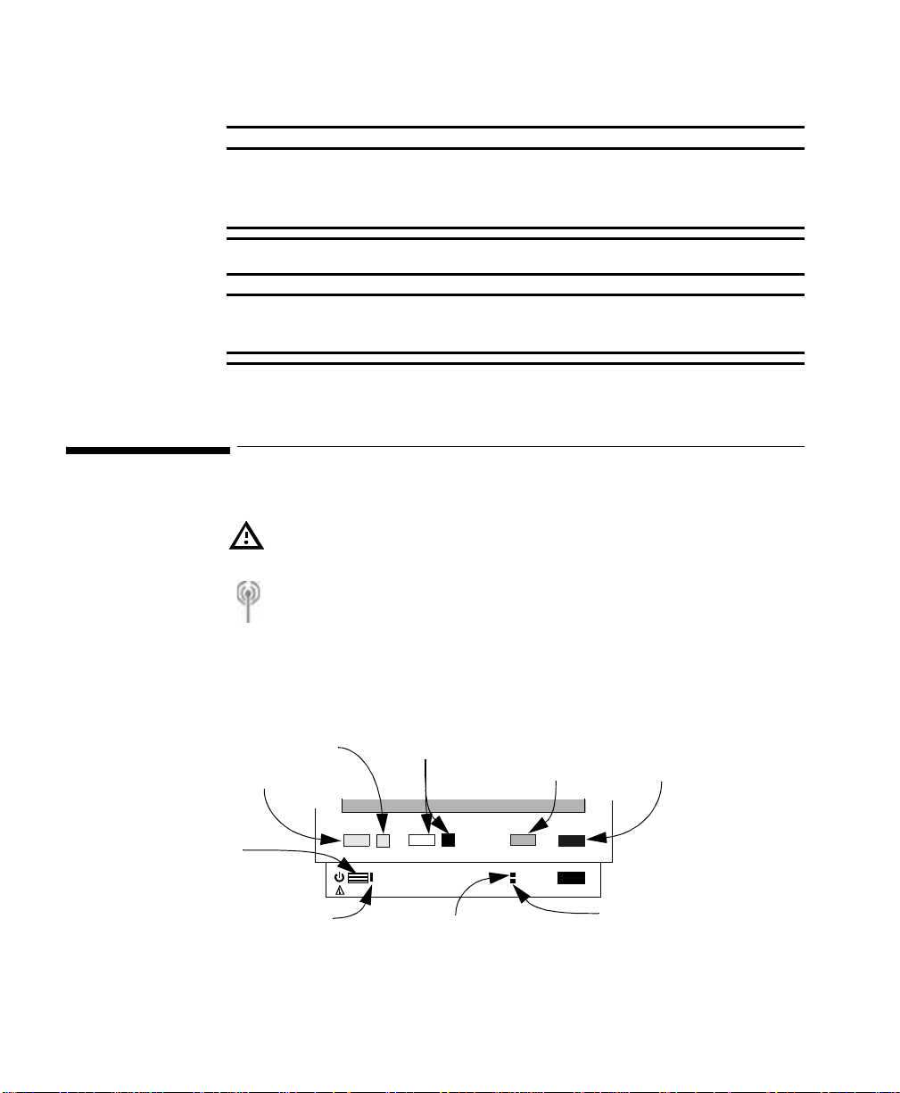
A Quick Description of the Monitor
Alarm
WarningWarning
Do not use portable phones in the vicinity of the monitor. Portable phones
may generate excessive radiated fields which can disturb the specified
function of the monitor.
WarningWarning
DO NOT TOUCH THE PATIENT, OR TABLE OR INSTRUMENTS DURING
DEFIBRILLATION.
A Quick Description of the Monitor
This symbol indicates that you should consult accompanying documents
(this guide), and particularly any warning messages.
This symbol on the handle of the monitor indicates that the mon i tor h as a
wireless network interface.
Front Panel Keys
Alarm
Silence/Reset Key
On Off/Standby
On Off/Standby LED
Green when monito r is on
30 Basic Operation
For an explanation of any of the other symbols on this monitor, see “Explanation
of symbols used:” on page 322.
Indicator
Alarm Suspend
Key & Indicator
Silence
Reset
On
Off/Standby
Suspend Setup
AC Power
Battery
Setup
Key
Main
Screen
Main Screen
Key
Battery LED
Green
- Battery full (>95%)
- Battery charging
AC Power LED
Green when AC Power
is Connected
Yellow
Blinking Red
- Battery empty
Page 31

Front of Monitor (M3046A)
l
c
Interface Port (optional)
P
p
Menu Highlight
Up Key
A Quick Des c ription of the Monitor
Menu Enter
Key
Menu
Highlight
Down Key
TouchStrips
Back of Monitor (M3046A)
Connector to
the Measurement
Server (≤48V)
Link bar
ECG Out/
Marker In (≤12V)
Equipotential
Grounding Post
AC Power
Connector
(100 to 240Va
50/60Hz)
Battery
Compartment
Infra-Red Printer/Seria
Locking Mechanism for
the Measurement Server
Catches for
attaching the
Measurement
Server
LAN/Software Update
Connector (≤5V)
Mounting Plate
rotective earth
in
Connector for an
additional display (≤3.3V)
Nurse Call Relay
Connector (≤36V)
Basic Operation
31
Page 32

A Quick Description of the Monitor
Measurement Server (M3001A)
Connector
to Monitor
Start/Stop
(for NBP)
STAT
(for NBP)
Alarm
Silence/Reset
Measurement Connectors (M3001A)
SpO
ECG/Resp
Measurement
Connectors
NBP
2
32 Basic Operation
Page 33

A Quick Des c ription of the Monitor
Measurement Server with Invasive Measurement Set (M3001A #C06, #C18)
Start/Stop
(for NBP)
Connector
to Monitor
Zero
(for Press)
Alarm
Silence/Reset
Measurement Connectors (M3001A #C06)
NBP
SpO
2
ECG/Resp
Press
Temp
Measurement
Connectors
Note:
If a Measurement Serv er Extension
with a second pressure capability is
connected, zero is appl ie d to both
pressures
Note:
Press and Temp cannot
be used at the same time.
Basic Operation
33
Page 34

A Quick Description of the Monitor
Measurement Server Extensions (M3015A & M3016A)
Catches for
attaching the
Measurement
Server
Connectors
to Monitor &
Measurement
Server
Note:
Measurement Server Extensions
can only be removed with a de dic a te d tool,
and should be done by a biomed or qualified
service personnel. Do NOT re move while monitoring
a patient.
Measurement
Connectors
34 Basic Operation
M3015A with Microstream CO
2
M3015 #C06 with Microstream CO2 plus Invasive Pressure and
Temperature
M3016A #A01 with Mainstream CO
plus Invasive Pressure and
2
Temperature
M3016A #A02 Invasive Pressure and Temperature only (no CO
)
2
Page 35

Measurement Server Extension Connectors
M3015A Measurement Server Extension
M3015A #C06 Measurement Server Extension
A Quick Des c ription of the Monitor
Note:
Press and Temp
cannot be used
at the same time
on the same Extension
M3016A Measurement Server Extension
Note:
Press and Temp
cannot be used
at the same time
on the same Extension
Sidestream CO
2
Press
Temp
Sidestream CO
2
Press
Temp
Mainstream CO
Basic Operation
(#A01 only)
2
35
Page 36

Before You Start to Use the Monitor
Bed/MonitorLabel
Main Screen
Network Symbol
Patient Name
Wave
Wave Label
Doe, John
II
Pleth
ABP
NBP
135
Start/Stop
You can return to the display with the waves and the numerics at any time by
pressing the blue Main Screen ke y
QuickSet
1 mV
120
0
/
Patient Size
Auto
101
NBP STAT
Stop All
Time
Sinus Rhythm
60min
17:15
(120)
STOP
Zero
Caregroup Status Symbol
Paced/Non-Paced Symbol
HR
70
SpO
2
PVC
5
97
ABP
120
70
/
(91)
Resp
mean
120
90
12
Store Screen
Trends
Alarm Messages
(Caregroup bed)
(this bed)
90
Numeric
65
100
90
sys.
150
100
Alarm
Limits
Numeric
Label
Alarm Off
Symbol
(measurement)
SmartKey Label/Icon
Before You Start to Use the Monitor
Before you start to take measurements for a patient, carry out the following
checks on the M3046A Monitor, the M3001A Measurement Server and the
M3015A/M3016A Server Extensions, where present:
• Check for any mechanical damage.
• Check all the external leads, plug-ins and accessories.
• Check all the functions of the instrument which will be needed to monitor
the patient, and ensure that the instrument is in good working order.
36 Basic Operation
Page 37

Before You Start to Use the Monitor
WarningWarning
Do not use the System for any monitoring procedure on a patient if the
monitor is not working properly, or if it is mechanically dam aged. Contact
the hospital biomedical engineer, or your supplier.
Step 1. Switch on the monitor. A self test is performed. (If there are any errors,
see “Basic Trouble shooting” on page 333).
After the self-test, the monitor is ready to use. If you need to make any changes
to the operation or the setup, see the section “Basic Operation”.
Step 2. Make sure the Measurement Server is connected to the monitor.
Step 3. If the patient is already attached to the Measurement Server, you should
see the configured waves and numerics on the display, otherwise
a. Attach any electrodes, probes, or transducers to the patient, or insert
any pressure catheters required for monitoring.
b. Connect the electrodes, probes and transducers to the Measurement
Server.
Basic Operation
37
Page 38

Basic Operation
Basic Operation
You operate the monitor using
Pressure Sensitive
TouchStrips at
both sides of
the screen
Silence/Reset Suspend
The Corners of
the TouchStrips
activate the bottom
line in the pop-up
windows
23:11
Alarms Suspended
(120)
Stop All
Pedi
HR
100
SpO
2
97
ABP
120
70
/
(91)
17:15
Resp
mean
120
12
90
Store Event
Trends
Setup
Zero
Doe, John
II
Pleth
ABP
NBP
135
1 mV
120
0
Start/Stop
/
60min
101
NBP STAT
four hardkeys below the TouchStrip,
90
70
100
90
sys.
150
100
The arrows and the
dot on the
TouchStrip at both
sides of the screen
SmartKeys or softkeys
on the TouchStrip
Main Screen
below the screen
The Four Hardkeys
38 Basic Operation
Silence/Reset Use this to stop the audible alarm signal, and to reset alarms
indicators for measurements that are no longer in an alarm
condition.
Page 39

Basic Operation
Suspend Use this to stop the monitor checking for patient and technical
(INOP) alarm conditions. To restart checking, press this key
again.
The Alarm Suspend indicator beside the key lights while the
alarms are suspended.
Depending on the configuration, the monitor may start
checking again automatically after a fixed time (the amount of
time for which the alarms will stay suspended is displayed in
this case).
Setup Use this key to setup the monitor. All of the monitor setup can
be accessed from the setup menu, along with the
measurements for the Measurement Server that is connected,
even if the measurement is not displayed on the screen.
Main Screen Use this key to return to the main screen with the waves and
numerics at any time.
The TouchStrip
The Arrows and the Dot
The TouchStrips at the left and right of the screen, and below it have two
pressure levels
Touch Press lightly on the TouchStrip to highlight something on the
screen. If you are on the main screen, touching the TouchStrip will
highlight the wave, numeric or SmartKey closest to your finger.
Press Press harder on the TouchStrip to select the currently highlighted
item.
Practice a few times to get to know the pressure difference between touching
and pressing reliably - you can practice by first highlighting and then selecting
the “Trends” SmartKey (press the blue Main Screen key to get back to the
main monitoring screen).
In a menu, touch the up or down arrow on the TouchStrip to move the highlight
to the next item.
If you hold your finger on the arrow, the highlight will continue moving through
the items in the menu.
Basic Operation
39
Page 40

Basic Operation
Press on the dot to select the item.
Note—You can also glide your finger to “drag” the highlight.
If you glide your finger to the arrow at the top or bottom of the T ouch Strip
and hold it there, the highlight will continue moving through the items in
the menu at the same speed.
You can use this to move through a menu quickly.
You can continue using the arrow keys for moving the highlight to nearby
items.
The SmartKeys and Softkeys
The SmartKeys are at the bottom of the Main screen. They give you fast access
to selected functions. A selection of SmartKeys are made for your monitor at the
factory, but these can be changed by your biomedical engineering staff or
Philips representative.
You can get access to other SmartKeys by pressing the TouchStrip beneath the
and the symbols.
In certain circumstances, such as when you are admitting a patient or examining
trend data, the SmartKeys are replaced by softkeys.
To highlight a SmartKey or a softkey, lightly touch the TouchStrip beneath it.
To select a SmartKey or a softkey, press harder on the TouchStrip beneath it.
mean
/
135
Silence/Reset Suspend
101
Start/Stop
NBP STAT
(120)
Stop All
120
12
90
Store Event
Trends
Setup
Main Screen
Zero
40 Basic Operation
Page 41

Basic Operation
97
High Limit
Low Limit
120
:
The Corner of the TouchStrip
Setting Up a
Measurement
1. If you have a window open on the screen, the left and right
lower corners of the TouchStrip activate the function displayed
on the bottom line of that window.
ABP
120
NBP
135
0
Start/Stop
HR from
ECG
/
60min
101
NBP STAT
(120)
Stop All
:
ECG
:
17:15
ABP
120
On
Zero
mean
120
More
90
Resp
12
Store Event
(91)
/
Trends
sys.
150
100
70
If the contents of a window is more than 8 lines long, the corners activate the
More to page down.
If you have paged down to the very bottom of a menu, the corners activate the
Exit, to close the menu.
Step 1. Highlight a measurement by lightly touching the TouchStrip beside the
numeric for that measurement. If there are two numerics next to each
other, move your finger on the TouchStrip until the one you want is
highlighted.
arms Suspended
HR
Non-paced mode
90
70
2.5 -3.0
1.2
2
100
90
sys.
150
100
70
/
33
100
ST
SpO
97
ABP
120
(91)
Resp
12
Trends
Store Event
Step 2. Select the highlighted measurement by pressing the TouchStrip.
The menu for that measurement is displayed.
Basic Operation
41
Page 42

Basic Operation
100
100
100
Step 3. Highlight the setting yo u want us ing the up or down arro w on the
TouchStrip, or by gliding your finger along the TouchStrip.
SpO
2
100
97
ABP
120
On
Zero
mean
120
More
90
Resp
12
Store Event
(91)
90
sys.
150
100
70
/
Trends
Setup
Main Screen
art/Stop
Alarms
High Limi t
Low Limit
HR from
ECG
/
101
Suspend
60min
NBP STAT
Setup ECG
:
:
:
:
:
(120)
Stop All
On
120
65
ECG
17:15
Step 4. Select the setting by pressing the dot on the TouchStrip
Setup ECG
art/Stop
Alarms
Channel
High Limit
Lead
Low Limit
Size Up
Size Down
HR from
Alarms
High Limit
ECG
Low Limit
/
101
60min
NBP STAT
Setup ECG
:
:
:
:
:
:
:
:
:
:
(120)
Stop All
On
ECG 1
120
MCL
ECG
On
120
On
17:15
SpO
2
100
/
Trends
90
sys.
150
100
70
97
ABP
120
80
Zero
More
mean
120
More
90
Resp
12
Store Event
(91)
42 Basic Operation
If there are a number of possible settings, these will be displayed and you
highlight the setting you want, and then select it.
Setup ECG
el
mit
mit
wn
imit
mit
min
Setup ECG
:
:
On
ECG
120
:
:
MCL
:
ECG
:
:
On
:
:
:
On
120
17:15
80
145
140
135
130
125
120
115
110
Cancel
mean
120
SpO
97
ABP
120
(91)
Resp
2
100
90
sys.
150
100
70
/
If there are only two possible settings, selecting the setting will change the
setting.
Page 43

Basic Operation
u
2
9
1
s
Setup ECG Channel 1
If you want to cancel editing without changing the setting, press the
bottom right or left hand corner to cancel.
Step 5. Continue editing settings until you have set up the measurement
Step 6. Press the blue Main Screen key, press the bottom right or left hand
corner to exit, or move the highlight to “Exit” at the very bottom of the
menu then press the TouchStrip.
Setting Up a Wave
Step 1. Highlight the wave by lightly touching the TouchStrip beside it
23:11
Alarms S
Doe, John
II
Pleth
ABP
NBP
1 mV
120
0
60min
Pedi
HR
ST
SpO
ABP
1
17:15
Re
mean
Select the highlighted wave by pressing the TouchStrip.
The list of waves are displayed.
Step 2. Press on the TouchStrip again to get the wave setup.
Step 3. Highlight the setti ng you wa nt to edit by touc hing or ho ldi ng your
finger on the up or down arrow on the TouchStrip, or by gliding your
finger along the TouchStrip.
Step 4. Select the setting by pressing the dot on the TouchStrip.
:
Lead
Size Up
Size Down
Next Channel
Setup ECG
/
rt/Stop
60min
101
NBP STAT
MCL
17:15
(120)
Stop All
SpO
2
100
/
Trends
90
sys.
150
100
70
97
ABP
120
(91)
More
Resp
mean
120
12
90
Zero
Store Event
Suspend
Setup
Main Screen
Basic Operation
43
Page 44

Basic Setup
u
2
9
1
s
1
E
Basic Setup
If the setting has a number of possible settings, these will be displayed and
you highlight the setting you want, and then select it.
If the setting only has a two possible settings, selecting the setting will
change the setting.
If you want to cancel editing without changing the setting of a setting,
press the bottom right or left hand corner to cancel.
Step 5. Continue editing settings until you have set up the wave.
Step 6. Press the blue Main Screen key, press the bottom right or left hand
corner to exit, or move the highlight to “Exit” at the very bottom of the
menu then press the TouchStrip.
Selecting a Wave for the Screen
44 Basic Operation
Step 1. Highlight the position on the screen where you want the wave to be
placed by touching the TouchStrip beside the position.
23:11
Alarms S
NBP STAT
(120)
Stop All
Pedi
17:15
HR
ST
SpO
ABP
1
Re
mean
120
90
Zero
Store
Doe, John
II
1 mV
Pleth
ABP
120
0
NBP
60min
135/101
Start/Stop
Silence/Reset Suspend
Step 2. Select the position by pressing the TouchStr ip.
The available waves for the position are displayed (the wave is only
available if the measurement is switched on).
Page 45

Basic Setup
Step 3. Highlight the wav e y ou want using th e u p or down arrow on the
TouchStrip, or by gliding your finger along the TouchStrip.
If you select Blank, the position will be kept clear (unless an ECG wave
cascades into the position).
(If you do not assign a wave, and do not mark the position Blank, then one will
be assigned automatically when you plug in a transducer that produces a wave.)
Step 4. Select the wave by pressing the TouchStrip.
If you want to exit editing without changing the wave, press the Main
Screen key.
You can also assign a wave to a position in the setup menu. Press the Setup key
then select Waves.
Setting the Waves Speed
Switching
Measurements On or
Off
Changing the Waves Speed does not affect the speed of respiratory waves. You
must set the speed of the respiratory waves separately (see “Changing the Speed
of the Respiration Wave” on page 184).
To set the wave speeds for all the waves on the screen,
Step 1. Press the Setup key.
Step 2. Move the highlight to “ Speed”.
This will set the speed for the waves except the respiration waves.
Step 3. Press on the TouchStrip.
Step 4. Select the appropriate setting.
Step 5. Select “Resp Speed”.
This will set the speed of the respiration waves.
Step 6. Select the appropriate setting.
Step 7. Exit the Setup menu.
To switch a particular measurement on or off, use the setup for that
measurement (see “Setting Up a Measurement” on page 41).
Basic Operation
45
Page 46

Basic Setup
Checking and Changing the Alarm Limits
Printing a
Copy of the
Current
Measurements
Recording Strips Locally
Adjusting the Volume
To check or change the alarm limits for a particular measurement, use the setup
for that measurement (see “Setting Up a Measurement” on page 41).
Caution
Make sure that the printer or recorder is connected and switched on before you
start printing or recording.
To print a copy of the current measurements to a connected printer,
press the Print Screen SmartKey (you may have to press or
to find this SmartKey, if it is configured).
Two types of local recording can be made: a real-time recording and a delayed
recording.
A real-time recording is started by pressing the Local Record
SmartKey. When a recording is running, you can stop it by pressing
the key again.
A delayed recording can be started by pressing the Local
Delayed SmartKey. Pressing the key again will extend the
recording.
WarningWarning
If you switch the Alarm Volume off, you will not get any audible indication
of alarm con d i tions.
Local
Record
Local
Delayed
46 Basic Operation
Step 1. Highlight the QRS Volume SmartKey to see the current
setting for the volume of the QRS tone (you may have to press
or to find this SmartKey, if it is configured).
Step 2. Press the QRS Volume SmartKey repeatedly to select the volume of
the QRS tone,.
The volume can be set from 1 to 10 (or 0, which is off, if this has not been
Page 47

Basic Setup
disabled). The current setting for the volume is displayed on the prompt
line as you press the SmartKey or touch it for 1/2 second.
Step 3. Highlight the Alarm Volume SmartKey to see the current
setting for the volume of the alarm tone (you may have to press
or to find this SmartKey, if it is configured).
Step 4. Press the Alarm Volume SmartKey repeatedly to select the volume
of the Alarm tone,.
The volume can be set from 1 to 10 (or 0, which is off, if this has not been
disabled). The current setting for the volume is displayed on the prompt
line as you press the SmartKey or touch it for 1/2 second.
OR
Step 1. Press the Setup key.
Step 2. If you want to change the setting for the QRS volume,
a. Move the highlight to “QRS Volume”.
b. Press on the TouchStrip.
c. Select the level for the QRS volume.
Step 3. If you want to change the setting for the alarm volume,
a. Move the highlight to “Alarm Volume”.
b. Press on the TouchStrip.
c. Select the appropriate setting for the alarm volume.
Step 4. Exit the Setup menu.
Adjusting the Screen Brightness
Step 1. To change the Brightness of the screen, press th e
Brightness SmartKey (you may have to press or to
find this SmartKey, if it is configured).
OR
a. Press the Setup key
b. Move the highlight to “Brightness”.
Step 2. Press on the TouchStrip.
Step 3. Select the appropriate set ting f or the scr een br ightness . 10 is t he
brightest, 1 the least bright and Optimum allows the monitor to adapt the
brightness automatically.
Step 4. Exit the Setup menu.
The brightness of the screen is reduced automatically when you power the
monitor from the battery, if it has been configured by your biomedical engineer.
Basic Operation
47
Page 48

Basic Setup
Setting the Date and Time
WarningWarning
Changing the date or time will affect the storage of trends and events
Step 1. Highlight the area at the top left of the screen by touching the
TouchStrip beside it and select it by pressing the TouchStrip.
OR
Press the Setup key.
Step 2. Move the highlight to “ Date, Time”.
Step 3. Highlight, then select the appropriate setting for the Year, Month, Day,
Hour (in 24 hour format, only) and Minute as necessary.
Step 4. Highlight and select Store Date, Time to change the date and
time.
Recalling a QuickSet
The default sets that are set in the factory for the monitor are described in
“Selecting a QuickSet” on page 97. A QuickSet is broadly equivalent to a
Profile in the IntelliVue family of patient monitors.
Note—If you change the QuickSet, any currently active automatic NBP
measurement will be stopped.
Step 1. To get into the QuickSets menu, press the QuickSets
SmartKey (you may have to press or to find this
SmartKey, if it is configured).
OR
a. Highlight the area at the top left of the screen (where the current
QuickSet is displayed) by touching the TouchStrip beside it and
select it by pressing the TouchStrip.
OR
b. Press the Setup key.
c. Move the highlight to “QuickSets”.
Step 2. Press on the TouchStrip.
The current QuickSet is highlighted, and displayed with an asterisk (*) beside it.
It is also displayed at the top left of the screen.
Step 3. Highlight the setting you want, and press on the TouchStrip to select it.
Step 4. Exit the Setup menu.
48 Basic Operation
Page 49

Summary of the SmartKeys
See “Printing a Copy of the Current Measurements” on
page 46
See “Adjusting the Screen Brightness” on page 47.
See page 47 or “Changing The Volume of the Alarm Chime”
on page 59.
See “Selecting the Patient Identification Menu” on page 94.
See page 48 or “Selecting a QuickSet” on page 97.
See page 46 or “Selecting the Volume of the Tone” on page
133.
See “Making a Single NBP Measurement” on page 193 and
“Making Automatic NBP Measurements” on page 194.
See “Making stat NBP Measurements” on page 193.
Summary of the SmartKeys
“Making a Single NBP Measurement” on page 193 and
“Making Automatic NBP Measurements” on page 194.
See “Using the NBP Cuff to Occlude Blood Vessels” on page
195.
See “Zeroing the Transducer” on page 207.
See “Viewing the Trend” on page 272.
See “Storing an Event Manually” on page 274.
See “Reviewing Events” on page 275.
See “Setting Automatic Alarm Limits” on page 59.
Basic Operation
49
Page 50

Summary of the SmartKeys
See “Setting Automatic Alarm Limits” on page 59.
See “Reviewing Beat Labels” on page 161.
Switches on Standby mode.
See “Relearning Arrhythmia” on page 161.
See “Changing the Size of the ECG Wave” on page 142.
See “Recording and Printing at the Information Center” on
page 110.
Record
See “Recording and Printing at the Information Center” on
page 110.
Delayed
Rec.
See “Recording Strips Locally” on page 46.
50 Basic Operation
Local
Record
See “Recording Strips Locally” on page 46.
Local
Delayed
See “Viewing Information for Other Patients from the Bedside” on page 115.
Page 51

Recommendation for Alarm Configuration
Dealing with Alarms
This chapter is about recognizing alarms, responding to alarms, setting up
alarms, and recording alarms.
A list of the physiological patient alarms, and the technical alarms (INOPs) is
given at the end of the chapter.
• Recognizing Alarms . . . . . . . . . . . . . . . . . . . . . . . . . . . . . . . . . . . . . . . 52
• Dealing with Alarms. . . . . . . . . . . . . . . . . . . . . . . . . . . . . . . . . . . . . . . 54
• Silencing Alarms. . . . . . . . . . . . . . . . . . . . . . . . . . . . . . . . . . . . . . . . . . 57
• Suspending Alarms. . . . . . . . . . . . . . . . . . . . . . . . . . . . . . . . . . . . . . . . 57
• Checking and Changing the Alarm Limits . . . . . . . . . . . . . . . . . . . . . . 58
• Changing The Volume of the Alarm Chime . . . . . . . . . . . . . . . . . . . . . 59
• Alarm Recording. . . . . . . . . . . . . . . . . . . . . . . . . . . . . . . . . . . . . . . . . . 60
• Patient Alarm Messages . . . . . . . . . . . . . . . . . . . . . . . . . . . . . . . . . . . . 61
• Technical Alarm Messages (INOPs). . . . . . . . . . . . . . . . . . . . . . . . . . . 76
Recommendation for Alarm Configuration
When using Arrhythmia Analysis it is recommended that both visual and
audible alarms are set to latching, or at least the visual red alarms.
During attended monito r ing (for example in the Operating Room), latching for
visual and audible alarms may be configured to OFF.
During unattended monitoring, it is recommended that both visual and audible
alarms are set to latching for red and yellow alarms.
See “Latching and Non-Latching Alarms” on page 54 for a description of
latching and non-latching behavior.
See “Changing How Alarms Behave Until Silenced” on page 370, for how to
make VisLatching and AudLatching settings.
Dealing with Alarms
51
Page 52

Recognizing Alarms
Recognizing Alarms
Patient Alarms
There are three types of patient alarm:
• A Red Alarm indicates a high priority patient alarm such as a life
threatening situation (for example, asystole).
• A Yellow Alarm indicates a lower priority patient alarm, (for example, a
blood pressure limit alarm).
• A Yellow Arrhythmia Alarm is specific to arrhythmia-related patient
conditions (for example, the ventricular bigeminy alarm).
Patient alarms are indicated by visual indicators and a sound.
The sound indicators for a patient alarm are as follows (if the volume has not
been turned down. See “Changing The Volume of the Alarm Chime” on
page 59):
• If there is a Red Alarm, the sound is higher pitched and repeated once a
second.
• If there is a Yellow Alarm (and no Red Alarms), the sound is lower
pitched and repeated every two seconds.
• If there is a Yellow Arrhythmia Alarm, the sound is at the same pitch as
the Yellow alarm but lasts for only 5 seconds.
The visual indicators for a patient alarm are:
• A message at the top right of the screen. Only the highest priority alarm
for a measurement is shown. If more than one measurement is in an alarm
condition, the message will change every 2 seconds, and it will have an
arrow ( ) at the side. [See “Reviewing Alarms” on following page for
how to see all current messages.]
For a red alarm, the message starts with three stars (***)
For all yellow alarms, the message starts with two stars (**)
• The numeric of the measurement in alarm blinks.
• A red or yellow lamp on the front panel blinks.
• If the alarm is due to the value for a measurement crossing an alarm limit,
and if this limit is displayed on the screen, then that alarm limit is
highlighted.
52 Dealing with Alarms
Page 53

Reviewing Alarms
• The alarm condition is also indicated on any device connected to the
Nurse Call Relay at the rear of the monitor, if the monitor is so configured
(see “Changing the Conditions for the Nurse Call Relay”).
Technical Alarms
Technical alarms (referred to as INOPs) indicate that the monitor cannot
measure or detect alarm conditions reliably. They are signalled by a message at
the top left of the screen (only the highest priority technical alarm is displayed
for a measurement). If more than one measurement has a technical alarm, the
message will change every 2 seconds, and it will have an arrow ( ) at the side.
Technical alarm conditions which cause an interruption of valid data and alarm
detection (for example, LEADS OFF) have an audible indicator (a different
sound at the same pitch as the yellow patient alarm, and repeated every 2
seconds).
Technical alarms without this audible indicator indicate that there might be a
problem with the validity of the data.
Reviewing Alarms
If more than one measurement is in an alarm condition, the message shown at
the top right of the screen will change every two seconds and it will have an
arrow ( ) at the side. To see a list of all current alarm messages, press on the
TouchStrip next to the alarm message.
To review all recent alarms, press the softkey Review Alarms. A window
with all the latest alarms is displayed, including any changes in the Alarms On/
Off or Alarms Silenced status.
If there is more than one alarm active within a channel, only the one with the
highest priority will be displayed in the corresponding text field, but all affected
numerics blink if alarms are active.
Dealing with Alarms
53
Page 54

Dealing with Alarms
Dealing with Alarms
Latching and
NonLatching
Alarms
Red & Yellow Parameter
Alarms
Silence/
Reset has
NOT been
activated.
Alarm
condition is
present
Alarm
condition no
longer present.
Alarm latching behavior for audible and visual alarms can be set separately. In
the alarm setup you can choose between three possible settings for Visual
Latching (Red&Yellow, Red Only, OFF) and up to three choices for Audible
Latching:
• Latching for Red and Yellow alarms (AudLatching or VisLatching set to
<Red&Yell> in the alarm setup).
• Latching for Red alarms only (set to <Red Only> in the alarm setup).
• Non-latching for all alarms (AudLatching or VisLatching set to <Off> in
the alarm setup).
Note—VisLatching can never be set for fewer alarms than AudLatching (this
means that it is e.g. not possible to set VisLatching to <Off> and at the same
time AudLatching to <RedOnly>)
How to set the latching setting for the alarm is described in “Changing How
Alarms Behave Until Silenced” on page 370.
The following tables describe the alarm behaviors for parameter and arrhythmia
alarms:
Visual latching
Non-latching alarms Latching alarms
Audible alarm sounds. Visual alarm message shown. Numerics blink.
Audible and Visual
alarms and blinking
numerics
automatically
reset.
Audible alarm sounds.
Visual alarm message
shown. Numerics
blink.
Audible non-latching
Visual alarm message
shown.
Numerics blink.
Audible alarm
automatically
resets.
54 Dealing with Alarms
Page 55

Dealing with Alarms
Red & Yellow Parameter
Alarms
Silence/
Reset has
been
activated.
Alarm
condition is
present.
Alarm
condition no
longer present
Yellow Arrhythmia
Alarms
Silence/
Reset has
NOT been
Alarm
condition is
present
activated.
Alarm
condition no
longer present.
Silence/
Reset has
been
activated.
Alarm
condition is
present.
Alarm
condition no
longer present.
Visual latching
Non-latching alarms Latching alarms
Audible non-latching
Audible alarm silenced. Audible alarm re-soun ds every 1, 2 or 3 mi nu tes
if configured.
Visual alarm message shown and numerics blink.
Audible and Visual alarms and blinking numerics reset.
Visual latching
Non-latching alarms Latching alarms
Audible non-latching
Audible alarm sounds for 5 seconds.
Visual alarm message shown and numeric blinks for at least 3 minutes.
Time-out period begins when alarm activated.
Visual alarm message disappears and numeric stops blinking after 3
minutes.
Visual alarm message shown and numeric blinks until condition clears.
Time-out period continues.
Visual alarm message disappears and numeric stops blinking.
Dealing with Alarms
55
Page 56

Dealing with Alarms
Red Arrhythmia Alarms
Silence/
Reset has
NOT been
Alarm
condition is
present
activated.
Alarm
condition no
longer present.
Non-latching alarms Latching alarms
Audible alarm sounds. Visual alarm message shown. Numeric blinks.
Audible and Visual
alarms and blinking
numerics
automatically
reset.
Audible alarm sounds.
Visual alarm message
shown. Numerics
a
blink.
Visual latching
Audible non-latching
Visual alarm message
shown. Numerics
Audible alarm
automatically
Silence/
Reset has
been
activated.
Alarm
condition is
present.
Audible alarm silenced. Audible alarm re-soun ds every 1, 2 or 3 mi nu tes
if configured. Reminder can be configured to either remind (short
reminder tone) or to ReAlarm (treated as new alarm)
Visual alarm message shown and numerics blink.
Alarm
condition no
Audible and Visual alarms and blinking numerics reset.
longer present.
a. For episodic alarms such as V-Tach or pause alarms, this may result in a very short alarm
sound and visual message.
b. For episodic alarms such as V-Tach or pause alarms, this may result in a very short alarm
sound.
blink.
resets.
b
56 Dealing with Alarms
Page 57

Silencing Alarms
Silencing Alarms
To stop the audible alarm indications, press the Silence/Reset key on the
Measurement Server (if it is enabled), or on the Monitor. If the patient is
centrally monitored, an alarm can also be silenced from the Philips Information
center (when Remote Silence is enabled, see “Configuring the Alarms” on page
369).
The visible alarm indicators will stop too, if the alarm conditions no longer exist.
Note Silencing an INOP which results from a disconnected transducer will normally
cause the associated measurement to be switched off. When such an INOP is
silenced from the Information Center, the measurement will not be switched off.
Suspending Alarms
To stop the monitor indicating alarms, press the Suspend key.
While the alarms are suspended the red light with a crossed bell beside the
Suspend key stays on, and the message Alarms Suspended is
displayed at the upper right corner of the screen.
The alarms can be suspended for 1 m inute, 2 minutes, 3 minutes or
infinitely. If the alarms have been suspended for 1, 2 or 3 minutes, the
remaining time is displayed with the Alarms Suspnd message. (See
“Changing How Long Alarms Stay Suspended” on page 369 about
configuring a restart period)
While alarms are suspended, no alarm messages are shown, INOPs are
shown, but there is no sound, and the Nurse Call relay is not active.
Dealing with Alarms
57
Page 58

Checking and Changing the Alarm Limits
Restarting Suspended Alarms
• If the monitor has been configured to only stay suspended for 1, 2 or 3
minutes, the monitor will start indicating alarms again after the
suspension period, or as soon as you press the Suspend key a second
time.
• If the monitor has been configured to stay suspended infinitely, you
will have to press the Suspend key again to restart the monitor
checking for alarm conditions.
Checking and Changing the Alarm Limits
There are two ways to set alarm limits.
You can set individual limits for each measurement as described in the
“Changing the Alarms” section in each of the measurement chapters.
You can also use the AutoLimits function of the monitor which sets limits for
you based on the trended measurement values for each measurement. The limits
are set when you use one of the AutoLimits SmartKeys (see “Setting
Automatic Alarm Limits” below) and will remain unchanged until you set them
again or change them manually. There are two SmartKeys:
Limits Narrow Sets limits close to the currently measured values for
situations where it is critical for you to be informed
about small changes in the vital signs
Limits Wide Sets limits further away from the currently measured
The measurements to be affected by the AutoLimits setting can be configured in
the password-protected Config operating mode.
58 Dealing with Alarms
values for situations where small changes are not so
critical.
Page 59

Changing The Volume of the Alarm Chime
Setting Automatic Alarm Limits
Caution When AutoLimits have been set, you must check the limits to ensure that
Step 1. Press the Limits Wide or Limits Narrow SmartKey (you may
have to press or to find these SmartKeys if they are configured).
Step 2. Select the appropriate setting: All for AutoLimits on all measurements
on the list or a specific measurement from the list for AutoLimits on that
measurement.
they are appropriate for your individual patient and their clinical condition.
Most limits can be seen next to the appropriate waves or numerics on the
Main Screen. If necessary, individual limits can be adjusted as described in
the “Changing the Alarms” section in each of the measurement chapters.
Changing The Volume of the Alarm Chime
WarningWarning
If you switch the Alarm Volume off, you will not get any audible indication
of alarm conditions.
Step 1. Highlight the Alarm Volume SmartKey to see the current
setting for the volume of the alarm tone (you may have to press
or to find this SmartKey, if it is configured).
Step 2. Press the Alarm Volume SmartKey repeatedly to select the volume
of the Alarm tone,.
The volume can be set from 1 to 10 (or 0, which is off, if this has not been
disabled). The current setting for the volume is displayed on the prompt
line as you press the SmartKey.
Dealing with Alarms
59
Page 60

Alarm Recording
OR
Step 1. Press the Setup key.
Step 2. Move the highlight to “ Alarm Volume”.
Step 3. Press on the TouchStrip.
Step 4. Select the level for the alarm volume.
Step 5. Exit the Setup menu.
Alarm Recording
If a local recorder is connected to the monitor via the optional serial interface, or
if the monitor is connected to a network, you can make alarm recordings. In
configuration mode, you can select the local recorder or the Information Center,
or both, to record alarms (See “Selecting Where to Make Alarm Recordings” on
page 373). If one of the configured alarms occurs, a recording for that alarm is
requested from the Information Center or started at the local recorder.
60 Dealing with Alarms
Page 61

Patient Alarm Messages
The alarms are listed alphabetically in the table (irrespective of their priority).
Technical alarms are listed in the section “Technical Alarm Messages (INOPs)”
on page 76.
Physiological Alarms
Patient Alarm Messages
Alarm Message
***ABP
DISCONNECT
Measurem
ent
Condition Visual Indication
PRESS Mean pressure is
continuously less than
10mmHg (1.3kPa)
** ABP HIGH PRESS Pressure above high
alarm limit
The s, d, or m after the
label indicates whether it
is the systolic, diastolic
or mean pressure that has
crossed the limit.
** ABP LOW PRESS Press ure below low
alarm limit
The s, d, or m after the
label indicates whether it
is the systolic, diastolic
or mean pressure that has
crossed the limit.
*** APNEA RESP The respiration has
stopped for longer than
the preset apnea time
ABP numeric
blinks,
Red alarm lamp
ABP numeric
blinks,
Yellow alarm lamp.
High limit is
highlighted only if
the pressure is
configure d for
single alarming
a
.
ABP numeric
blinks, Yellow
alarm lamp. Low
limit is highlighted
only if the pressure
is configured for
single alarming
a
.
RR numeric blinks,
Red alarm lamp
Audible
Indication
A chime
every
second.
A chime
every 2
seconds.
A chime
every 2
seconds.
A chime
every
second.
*** APNEA CO
AwRR
2
The respiration has
stopped for longer than
the preset apnea time
AwRR numeric
blinks,
Red alarm lamp
Dealing with Alarms
A chime
every
second.
61
Page 62

Patient Alarm Messages
Physiological Alarms
Alarm Message
***ART
DISCONNECT
Measurem
ent
Condition Visual Indication
PRESS Mean pressure is
continuously less than
10mmHg (1.3kPa)
** ART HIGH PRESS Pressure above high
alarm limit
The s, d, or m after the
label indicates whether it
is the systolic, diastolic
or mean pressure that has
crossed the limit.
** ART LOW PRESS Pressure be low low
alarm limit
The s, d, or m after the
label indicates whether it
is the systolic, diastolic
or mean pressure that has
crossed the limit.
***Ao
DISCONNECT
PRESS Mean pressure is
continuously less than
10mmHg (1.3kPa)
ART numeric
blinks,
Red alarm lamp
ART numeric blinks
Yellow alarm lamp.
High limit is
highlighted only if
the pressure is
configure d for
single alarming
a
.
ART numeric blinks
Yellow alarm lamp.
Low limit is
highlighted only if
the pressure is
configure d for
single alarming
a
.
Ao numeric blinks,
Red alarm lamp
Audible
Indication
A chime
every
second.
A chime
every 2
seconds.
A chime
every 2
seconds.
A chime
every
second.
** Ao HIGH PRESS Pressure above high
alarm limit
The s, d, or m after the
label indicates whether it
is the systolic, diastolic
or mean pressure that has
crossed the limit.
62 Dealing with Alarms
Ao numeric blinks
Yellow alarm lamp.
High limit is
highlighted only if
the pressure is
configure d for
single alarming
a
A chime
every 2
seconds.
Page 63

Physiological Alarms
Patient Alarm Messages
Alarm Message
Measurem
ent
Condition Visual Indication
** Ao LOW PRESS Press ure below low
alarm limit
The s, d, or m after the
label indicates whether it
is the systolic, diastolic
or mean pressure that has
crossed the limit.
*** ASYSTOLE ECG No QRS complex
detected for a period
greater than the set
asystole threshold.
** AWRR HIGH CO
AwRR
2
The airway respiration
rate has exceeded the
high alarm l imit
** AWRR LOW CO
AwRR
2
The airway respiration
rate has dropped below
the low alarm limit
Ao numeric blinks
and Yellow alarm
lamp. Low limit is
highlighted only if
the pressure is
configure d for
single alarming
a
.
HR numeric blinks,
Red alarm lamp
AwRR numeric
blinks and high
limit is highlighted,
Yellow alarm lamp.
AwRR numeric
blinks and low limit
is highlighted
Yellow alarm lamp
Audible
Indication
A chime
every 2
seconds.
A chime
every
second.
A chime
every 2
seconds.
A chime
every 2
seconds
** CVP HIGH PRESS Pressure above high
alarm limit
The s, d, or m after the
label indicates whether it
is the systolic, diastolic
or mean pressure that has
crossed the limit.
CVP numeric blinks
Yellow alarm lamp
High limit is
highlighted only if
the pressure is
configure d for
single alarming
a
Dealing with Alarms
A chime
every 2
seconds.
63
Page 64

Patient Alarm Messages
Physiological Alarms
Alarm Message
Measurem
ent
Condition Visual Indication
** CVP LOW PRESS Pressure below low
alarm limit
The s, d, or m after the
label indicates whether it
is the systolic, diastolic
or mean pressure that has
crossed the limit.
*** DESAT SpO
2
The SpO2 value has
fallen below the
desaturation alarm limit.
/
**EtCO2 LOW msCO
ssCO
**EtCO2 HIGH msCO
ssCO
*** EXTREME
ECG The heart rate has
BRADY
2
2
2
2
EtCO2 has dropped
below the selected low
limit.
/
EtCO2 has exceeded the
selected high limit
dropped bel ow the
selected bradycardia
limit.
CVP numeric blinks
Yellow alarm lamp.
Low limit is
highlighted only if
the pressure is
configure d for
single alarming
a
.
Numeric flashes,
Red alarm lamp
EtCO2 numeric
blinks and low limit
is highlighted,
Yellow alarm lamp
EtCO2 numeric
blinks and high
limit is highlighted,
Yellow alarm lamp
HR numeric blinks,
Red alarm lamp
Audible
Indication
A chime
every 2
seconds.
Alarm
tone
A chime
every 2
seconds.
A chime
every 2
seconds.
A chime
every
second.
*** EXTREME
TACHY
ECG The heart rate has
exceeded the selected
tachycardia limit
** HR HIGH ECG The heart rate has
exceeded the high alarm
limit
64 Dealing with Alarms
HR numeric blinks,
Red alarm lamp
HR numeric blinks
and high limit is
highlighted,
Yellow alarm lamp.
A chime
every
second.
A chime
every 2
seconds.
Page 65

Physiological Alarms
Patient Alarm Messages
Alarm Message
Measurem
ent
Condition Visual Indication
** HR LOW ECG The heart rate has
dropped below the low
alarm limit
** ICP HIGH PRESS Pressure above high
alarm limit
The s, d, or m after the
label indicates whether it
is the systolic, diastolic
or mean pressure that has
crossed the limit.
** ICP LOW PRES S Pressure below low
alarm limit
The s, d, or m after the
label indicates whether it
is the systolic, diastolic
or mean pressure that has
crossed the limit.
Audible
Indication
The sound switches off after 5
seconds if Arrhythmia is ON, and
the HR source is ECG
HR numeric blinks
and low limit is
highlighted,
A chime
every 2
seconds.
Yellow alarm lamp.
The sound switches off after 5
seconds if Arrhythmia is on, and
the HR source is ECG
ICP numeric blinks
and high limit is
highlighted, if the
A chime
every 2
seconds.
pressure is
configure d for
single alarming
Yellow alarm lamp
ICP numeric blinks
and low limit is
highlighted, if the
A chime
every 2
seconds.
pressure is
configure d for
single alarming
Yellow alarm lamp
**IMCO2 HIGH msCO
ssCO
/
2
2
ImCO2 has exceeded the
selected high limit
ImCO2 blinks and
high limit is
highlighted, Yellow
A chime
every 2
seconds.
alarm lamp
Dealing with Alarms
65
Page 66

Patient Alarm Messages
Physiological Alarms
Alarm Message
** IRREGULAR
c
HR
Measurem
ent
ECG/
Arrhythmia
Condition Visual Indication
Consistently irregular
heart rhythm.
** LAP HIGH PRESS Pressure above high
alarm limit
The s, d, or m after the
label indicates whether it
is the systolic, diastolic
or mean pressure that has
crossed the limit.
** LAP LOW PRESS Pressure below low
alarm limit
The s, d, or m after the
label indicates whether it
is the systolic, diastolic
or mean pressure that has
crossed the limit.
** MISSED
BEAT
ECG/
Arrhythmia
(enhanced)
If HR is less than
120bpm, then an omitted
beat was detected.
If HR is greater than
120bpm then there was
no beat for 1 second.
HR numeric blinks,
Yellow alarm lamp
LAP numeric blinks
Yellow alarm lamp
High limit is
highlighted only if
the pressure is
configure d for
single alarming
a
LAP numeric blinks
and low limit is
highlighted, if the
pressure is
configure d for
single alarming
Yellow alarm lamp
Numeric flashes,
Yellow alarm lamp
Audible
Indication
A chime
every 2
seconds
for 5
seconds.
A chime
every 2
seconds.
A chime
every 2
seconds.
A chime
every 2
seconds
for 5
seconds.
** MULTIFORM PVCs
c
66 Dealing with Alarms
ECG/
Arrhythmia
The occurrence of two
different shaped PVCs in
the last 300 beats,
repeated in the last 60
beats
PVC numeric
blinks,
Yellow alarm lamp
A chime
every 2
seconds
for 5
seconds.
Page 67

Physiological Alarms
Patient Alarm Messages
Alarm Message
Measurem
ent
Condition Visual Indication
** NBP HIGH NBP NBP above the high
alarm limit.
The s, d, or m after the
label indicates whether it
is the systolic, diastolic
or mean pressure that has
crossed the limit.
** NBP LOW NBP NBP below th e low
alarm limit for.
The s, d, or m after the
label indicates whether it
is the systolic, diastolic
or mean pressure that has
crossed the limit.
** NONSUSTAIN VT
c
ECG/
Arrhythmia
A short run of PVCs
were detected
accompanied by a
heartrate greater than the
ventricular tachycardia
limit.
NBP numeric blinks
Yellow alarm lamp.
High limit is
highlighted only if
the pressure is
configure d for
single alarming
a
NBP numeric blinks
and low limit is
highlighted, if the
pressure is
configure d for
single alarming
Yellow alarm lamp.
PVC numeric
blinks,
Yellow alarm lamp
Audible
Indication
A chime
every 2
seconds.
A chime
every 2
seconds.
A chime
every 2
seconds
for 5
seconds.
***P1
DISCONNECT
PRESS Mean pressure is
continuously less than
10mmHg (1.3kPa)
** P1 HIGH PRESS Pressure above high
alarm limit
The s, d, or m after the
label indicates whether it
is the systolic, diastolic
or mean pressure that has
crossed the limit.
P1 numeric blinks,
Red alarm lamp
P1 numeric blinks
and Yellow alarm
lamp.
High limit is
highlighted only if
the pressure is
configure d for
single alarming
a
Dealing with Alarms
A chime
every
second.
A chime
every 2
seconds.
67
Page 68

Patient Alarm Messages
Physiological Alarms
Alarm Message
Measurem
ent
Condition Visual Indication
** P1 LOW PRE S S Pressure below low
alarm limit
The s, d, or m after the
label indicates whether it
is the systolic, diastolic
or mean pressure that has
crossed the limit.
** PACER NOT
b
CAPT
ECG/
Arrhythmia
A missed beat with a
pace pulse was detected.
(Paced
patients
only)
** PACER NT
PACING
b
ECG/
Arrhythmia
A missed beat without a
pace pulse was detected.
(Paced
patients
only)
** PAIR PVCs
c
ECG/
Arrhythmia
A non-ventricular
contraction, followed by
two ventricular
contractions followed by
a non-ventricular
contraction has been
detected.
P1 numeric blinks
and Yellow alarm
lamp. Low limit is
highlighted only if
the pressure is
configure d for
single alarming
a
.
HR numeric blinks,
Yellow alarm lamp
HR numeric blinks,
Yellow alarm lamp
PVC numeric
blinks,
Yellow alarm lamp
Audible
Indication
A chime
every 2
seconds.
A chime
every 2
seconds
for 5
seconds.
A chime
every 2
seconds
for 5
seconds.
A chime
every 2
seconds
for 5
seconds.
***PAP
DISCONNECT
68 Dealing with Alarms
PRESS Mean pressure is
continuously less than
10mmHg (1.3kPa)
PAP numeric
blinks,
Red alarm lamp
A chime
every
second.
Page 69

Physiological Alarms
Patient Alarm Messages
Alarm Message
Measurem
ent
Condition Visual Indication
** PAP HIGH PRESS Pressure above high
alarm limit
The s, d, or m after the
label indicates whether it
is the systolic, diastolic
or mean pressure that has
crossed the limit.
** PAP LOW P R ESS Pressure be low low
alarm limit
The s, d, or m after the
label indicates whether it
is the systolic, diastolic
or mean pressure that has
crossed the limit.
** PAUSE
c
ECG/
Arrhythmia
No QRS complex
detected for a period
greater than the set pause
threshold.
** PVC/min
b
HIGH
ECG/
Arrhythmia
More premature
ventricular contractions
have been detected in a
minute than the limit.
PAP numeric blinks
Yellow alarm lamp.
High limit is
highlighted only if
the pressure is
configure d for
single alarming
a
PAP numeric blinks
Yellow alarm lamp.
Low limit is
highlighted only if
the pressure is
configure d for
single alarming
a
.
HR numeric blinks,
Yellow alarm lamp
PVC numeric
blinks,
Yellow alarm lamp
Audible
Indication
A chime
every 2
seconds.
A chime
every 2
seconds.
A chime
every 2
seconds.
for 5
seconds
A chime
every 2
seconds
for 5
seconds.
** PULSE HIGH PRESS
SpO
2
** PULSE LOW PRESS
SpO
2
The pulse rate has
exceeded the high alarm
limit
The pulse rate has
dropped below the low
alarm limit
Pulse numeric
blinks and high
limit is highlighted,
Yellow alarm lamp.
Pulse numeric
blinks and low limit
is highlighted,
Yellow alarm lamp.
Dealing with Alarms
A chime
every 2
seconds.
A chime
every 2
seconds.
69
Page 70

Patient Alarm Messages
Physiological Alarms
Alarm Message
Measurem
ent
Condition Visual Indication
** RAP HIGH PRESS Pressure above high
alarm limit
The s, d, or m after the
label indicates whether it
is the systolic, diastolic
or mean pressure that has
crossed the limit.
** RAP LOW PRESS Pressure below low
alarm limit
The s, d, or m after the
label indicates whether it
is the systolic, diastolic
or mean pressure that has
crossed the limit.
** RR HIGH RESP The respiratio n ra te has
exceeded the high alarm
limit
** RR LOW RESP The respiration rate has
dropped below the low
alarm limit
RAP numeric blinks
Yellow alarm lamp.
High limit is
highlighted only if
the pressure is
configure d for
single alarming
a
RAP numeric blinks
and low limit is
highlighted only if
the pressure is
configure d for
single alarming
a
Yellow alarm lamp
RR numeric blinks
and high limit is
highlighted,
Yellow alarm lamp.
RR numeric blinks
and low limit is
highlighted,
Yellow alarm lamp.
Audible
Indication
A chime
every 2
seconds.
A chime
every 2
seconds.
A chime
every 2
seconds.
A chime
every 2
seconds.
** RUN PVCs
c
HIGH
70 Dealing with Alarms
ECG/
Arrhythmia
More than 2 consecutive
premature ventricular
contractions have been
detected.
PVC numeric
blinks,
Yellow alarm lamp
A chime
every 2
seconds
for 5
seconds.
Page 71

Physiological Alarms
Patient Alarm Messages
Alarm Message
** R-ON-T PVCs
** SpO
** SpO
HIGH SpO
2
LOW SpO
2
Measurem
ent
c
ECG/
Arrhythmia
Condition Visual Indication
If the heart rate is less
than 100bpm, a PVC
with R to R interval less
PVC numeric
blinks,
Yellow alarm lamp
than one third of a second
and less than one third of
Audible
Indication
A chime
every 2
seconds
for 5
seconds.
the average R to R
interval, followed by a
compensatory pause.
Or two such ventricular
contractions without a
compensatory pause
within 5 minutes.
2
The arterial oxygen
saturation has exceeded
the high alarm limit
SpO2 numeric
blinks and high
limit is highlighted,
A chime
every 2
seconds.
Yellow alarm lamp.
2
The arterial oxygen
saturation has dropped
below the low alarm
limit
SpO
numeric
2
blinks and low limit
is highlighted,
Yellow alarm lamp.
A chime
every 2
seconds.
** ST<n> HIGH ECG/
Arrhythmia
(Adult
patients
only)
** ST<n> LOW ECG/
Arrhythmia
(Adult
patients
only)
The ST segment in lead
<n> is higher than the
limit.
The ST segment in lead
<n> is lower than the
limit.
ST numeric blinks,
Yellow alarm lamp
STnumeric blinks,
Yellow alarm lamp
Dealing with Alarms
A chime
every 2
seconds
A chime
every 2
seconds.
71
Page 72

Patient Alarm Messages
Physiological Alarms
Alarm Message
** SVT
c
Measurem
ent
Condition Visual Indication
Arrhythmia A run of supraventricu lar
beats greater than the
SVT run limit has been
detected and the HR has
exceeded the SVT HR
limit.
** T1 HIGH TEMP The temperature has
exceeded the high alarm
limit
**T1 LOW TEMP The temperature has
dropped below the low
alarm limit
** Tart HIGH TEMP The temperature has
exceeded the high alarm
limit
**Tart LOW TEMP The temperature has
dropped below the low
alarm limit
HR numeric blinks,
Yellow alarm lamp
T1 numeric blinks
and high limit is
highlighted,
Yellow alarm lamp.
T1 numeric blinks
and low limit is
highlighted,
Yellow alarm lamp.
Tart numeric blinks
and high limit is
highlighted,
Yellow alarm lamp.
Tart numeric blinks
and low limit is
highlighted,
Yellow alarm lamp.
Audible
Indication
A chime
every 2
seconds
for 5
seconds.
A chime
every 2
seconds.
A chime
every 2
seconds.
A chime
every 2
seconds.
A chime
every 2
seconds.
** Tcore HIGH TEMP The temperature has
exceeded the high alarm
limit
**Tcore LOW TEMP The temperature has
dropped below the low
alarm limit
72 Dealing with Alarms
Tcore numeric
blinks and high
limit is highlighted,
Yellow alarm lamp.
Tcore numeric
blinks and low limit
is highlighted,
Yellow alarm lamp.
A chime
every 2
seconds.
A chime
every 2
seconds.
Page 73

Physiological Alarms
Patient Alarm Messages
Alarm Message
Measurem
ent
Condition Visual Indication
** Tesop HIGH TEMP The temperature has
exceeded the high alarm
limit
**Tesop LOW TEMP The temperature has
dropped below the low
alarm limit
** Tnaso HIGH TEMP The temperature has
exceeded the high alarm
limit
**Tnaso LOW TEMP The temperature has
dropped below the low
alarm limit
** Trect HIGH TEMP The temperature has
exceeded the high alarm
limit
Tesop numeric
blinks and high
limit is highlighted,
Yellow alarm lamp.
Tesop numeric
blinks and low limit
is highlighted,
Yellow alarm lamp.
Tnaso numeric
blinks and high
limit is highlighted,
Yellow alarm lamp.
Tnaso numeric
blinks and low limit
is highlighted,
Yellow alarm lamp.
Trect numeric
blinks and high
limit is highlighted,
Yellow alarm lamp.
Audible
Indication
A chime
every 2
seconds.
A chime
every 2
seconds.
A chime
every 2
seconds.
A chime
every 2
seconds.
A chime
every 2
seconds.
**Trect LOW TEMP The temperature has
dropped below the low
alarm limit
** Tskin HIGH TEMP The temperature has
exceeded the high alarm
limit
Trect numeric
blinks and low limit
is highlighted,
Yellow alarm lamp.
Tskin numeric
blinks and high
limit is highlighted,
Yellow alarm lamp.
Dealing with Alarms
A chime
every 2
seconds.
A chime
every 2
seconds.
73
Page 74

Patient Alarm Messages
Physiological Alarms
Alarm Message
Measurem
ent
Condition Visual Indication
**Tskin LOW TEMP The temperature has
dropped below the low
alarm limit
** Tven HIGH TEMP The temperature has
exceeded the high alarm
limit
**Tven LOW TEMP The temperature has
dropped below the low
alarm limit
***UAP
DISCONNECT
PRESS Mean pressure is
continuously less than
10mmHg (1.3kPa)
** UAP HIGH PRESS Pressure above high
alarm limit
The s, d, or m after the
label indicates whether it
is the systolic, diastolic
or mean pressure that has
crossed the limit.
Tskin numeric
blinks and low limit
is highlighted,
Yellow alarm lamp.
Tven numeric blinks
and high limit is
highlighted,
Yellow alarm lamp.
Tven numeric blinks
and low limit is
highlighted,
Yellow alarm lamp.
UAP numeric
blinks,
Red alarm lamp
UAP numeric blinks
Yellow alarm lamp.
High limit is
highlighted only if
the pressure is
configure d for
single alarming
a
Audible
Indication
A chime
every 2
seconds.
A chime
every 2
seconds.
A chime
every 2
seconds.
A chime
every
second.
A chime
every 2
seconds.
** UAP LOW PRESS Pressure below low
alarm limit
The s, d, or m after the
label indicates whether it
is the systolic, diastolic
or mean pressure that has
crossed the limit.
74 Dealing with Alarms
UAP numeric blinks
Yellow alarm lamp.
Low limit is
highlighted only if
the pressure is
configure d for
single alarming
a
.
A chime
every 2
seconds.
Page 75

Physiological Alarms
Patient Alarm Messages
Alarm Message
Measurem
ent
Condition Visual Indication
** UVP HIGH PRESS Pressure above high
alarm limit
The s, d, or m after the
label indicates whether it
is the systolic, diastolic
or mean pressure that has
crossed the limit.
** UVP LOW PRESS Pressure below low
alarm limit
The s, d, or m after the
label indicates whether it
is the systolic, diastolic
or mean pressure that has
crossed the limit.
** VENT
BIGEMINY
c
*** VENT FIB/
TACH
ECG/
Arrhythmia
A dominant bigeminy
rhythm was detected.
ECG Fibrillatory waveform
for 4 consecutive
seconds.
UVP numeric blinks
Yellow alarm lamp.
High limit is
highlighted only if
the pressure is
configure d for
single alarming
a
UVP numeric blinks
Yellow alarm lamp.
Low limit is
highlighted only if
the pressure is
configure d for
single alarming
a
.
PVC numeric
blinks,
Yellow alarm lamp
HR numeric blinks,
Red alarm lamp
Audible
Indication
A chime
every 2
seconds.
A chime
every 2
seconds.
A chime
every 2
seconds
for 5
seconds.
A chime
every
second.
** VENT
RHYTHM
c
** VENT
TRIGEMINY
ECG/
Arrhythmia
A consecutive run of
PVCs has been detected
accompanied by a rate
PVC numeric
blinks,
Yellow alarm lamp
less than the limit for
ventricular tachycardia.
c
Arrhythmia
ECG/
A dominant trigeminy
rhythm was detected.
PVC numeric
blinks,
Yellow alarm lamp
A chime
every 2
seconds
for 5
seconds.
A chime
every 2
seconds
for 5
seconds.
Dealing with Alarms
75
Page 76

Technical Alarm Messages (INOPs)
Physiological Alarms
Alarm Message
*** VTACH
b
Measurem
ent
ECG/
Arrhythmia
Condition Visual Indication
Ventricular tachycardia
has been detected
PVC numeric
blinks,
Red alarm lamp
a. If configured for m ul ti ple al arms (e.g. s&d&m), e.g. the string ‘Sys’ wi ll be highlighted if a systolic alarm is acti ve , and
likewise ‘Dia’ for diastolic or ‘Mean’ when mean pressure alarm is active.
b. These messages a ppear with Basic Ar rh y th mia
c. These messages only appear with the Enhanced Arrhythmia option
Audible
Indication
A chime
every
second.
Technical Alarm Messages (INOPs)
This table lists all of the technical alarm messages (in alphabetic order) that
could appear at the top left of the screen. If a status message with yellow text on
a blue background appears at the bottom of the screen, check with your
biomedica l department .
Technical Alarms (INOPs)
INOP Message
Measurement
What to do.
nothing on screen Contact your biomedical department.
(The connector to the screen is
disconnected.)
ABP INOPS PRESS See P1 INOPS
ALL ECG
ALARMS OFF
ECG/
Arrhyth
All ECG alarms have been switched
off or the HR source is not ECG
mia
ART INOPS PRESS See P1 INOPS
76 Dealing with Alarms
Visual
Indication
Audible
Indication
A beep
every 2
seconds.
Page 77

Technical Alarms (INOPs)
Technical Alarm Messages (INOPs)
INOP Message
Measurement
What to do.
Ao INOPS PRESS See P1 INOPS
BAD SERVER
LINK
You cannot use this combination of
Monitor, Measurement Server and
cable.
Switch off the monitor and contact
your biomedical department.
BAD SERVER
LINK
plus
“Measurement
Server Revision
not supported”
An M3000A Measurement Server
with revision A software is
connected to an M3046A Monitor
with a software revision of B or later.
This combination does not allow
monitoring.
status message in
red.
BATTERY
EMPTY
Change the battery immediately. It is
nearly empty.
This INOP cannot
be suspended or
switched off.
This INOP repeats
every 3 minutes.
Visual
Indication
Audible
Indication
A beep
every 2
seconds.
BATTERY LOW Change the Battery.
The battery has less than 20 minutes
charge left.
BATTERY
MALFUNCT.
The status of the battery cannot be
determined.
If this is a new battery, leave the
This INOP cannot
be suspended or
switched off.
This INOP repeats
every 3 minutes.
battery in the monitor and wait to see
if the INOP clears after a few
minutes. If not, or if this is an older
battery, change the battery at the first
opportunity.
A beep
every 2
seconds.
Battery
Symbol
A beep
every 2
seconds.
Dealing with Alarms
77
Page 78

Technical Alarm Messages (INOPs)
Technical Alarms (INOPs)
INOP Message
Measurement
What to do.
C LEAD OFF ECG Check that the chest electrode is in
place and securely attached.
CANNOT
ANALYZE ECG
CANNOT
ANALYZE ST
CHARGER
MALFUNCT.
Arrhythmia
Check all leads and review ECG
signal quality.
ST Review the ECG signal quality and
the placement of the ISO and J points
Contact your biomedical department.
(The battery charging hardware or
the battery is faulty)
CHECK INPUT
DEVICE
Make sure that nothing is pressing on
the keys or the TouchStrip of the
monitor.
If this is not the problem, contact
your biomedical department.
(The monitor has detected 5 minutes
or more of constant user interface
operation, or the user interface
hardware is faulty).
Visual
Indication
HR
numeric
might
display -?for 10
seconds.
Battery
Symbol
Audible
Indication
A beep
every 2
seconds.
A beep
every 2
seconds.
None
78 Dealing with Alarms
Page 79

Technical Alarms (INOPs)
Technical Alarm Messages (INOPs)
INOP Message
CHECK STATUS
LOG
CO
AUTO ZERO ssCO
2
Measurement
2
What to do.
An error condition occurred on the
monitor and information about it has
been saved in the Status Log. View
this information as described in
“Finding Intermittent Status” on
page 307. When you have viewed the
information, the INOP is cleared.
Note: Do not clear the status log, as
the information may be useful if
faults occu r which requ i re diagnos is
from a service engineer.
Auto Zero is in progress, no action
required.
Visual
Indication
Numeric is
displayed
with a ?
for the first
15
seconds.
After 15
seconds
the
numeric
displays
-?-
Audible
Indication
A beep
every 2
seconds
After 15
seconds, a
beep every
2 seconds
CO
EQUIP
2
MALF
msCO2/
ssCO
2
Contact your biomedical department.
[Either 1) the CO
hardware or
2
firmware in the M3015A
Measurement server extension is
incompatible with the M3001A
Measurement Server or M3046A
monitor, or 2) the CO
hardware is
2
faulty.]
CO
2
numeric
displays
A beep
every 2
seconds
-?-
Dealing with Alarms
79
Page 80

Technical Alarm Messages (INOPs)
Technical Alarms (INOPs)
INOP Message
CO2 NO
TRANSDUCER
CO
CAL
2
FAILED
CO
CHECK CAL msCO
2
CO
SENSOR
2
WARMUP
Measurement
msCO
msCO
msCO2/
ssCO
2
What to do.
Make sure the CO2 transducer is
2
connected.
If you silence this INOP the CO
measurement will be switched off.
Make sure that the transducer is on
2
the correct cell and that the power
has not failed. Repeat the calibration.
If the problem persists, call your
biomedica l department.
Perform an accuracy check (see
2
“Preparing to Measure CO
page 247) and, if necessary,
recalibrate the transducer.
Wait for the sensor to reach operating
temperature (INOP disappears).
” on
2
Visual
Indication
CO
2
numeric
2
displays
Audible
Indication
A beep
every 2
seconds
-?CO
2
numeric
displays
A beep
every 2
seconds
-?-
CO
2
numeric
displays
A beep
every 2
seconds
-?CO2
numeric
displays
-?- for
ssCO
.
2
CO
2
A beep
every 2
seconds
for ssCO
None for
msCO
.
2
.
2
numeric is
displayed
with a ?
for msCO
2
WAIT CAL2 msCO
CO
2
CO
CAL
2
RUNNING
80 Dealing with Alarms
msCO
Start the CAL2 calibration cycle (see
2
“Preparing to Measure CO
” on
2
page 247)
Wait until calibration is complete. CO2
2
CO
2
numeric
displays
-?-
numeric
displays
-?-
None
None
Page 81

Technical Alarms (INOPs)
Technical Alarm Messages (INOPs)
INOP Message
CO
CAL MODE msCO
2
CO
CHANGE
2
SCALE
PURGING ssCO
CO
2
CO
2
OVERRANGE
Measurement
msCO2/
ssCO
2
2
ssCO
2
What to do.
Start calibration, if required, or
2
switch cal mode off.
Switch to larger scale so that the
whole wave can be displayed.
The Measurement Extension is
purging the Filterline. This occurs
when an occlusion is detected in the
line or airway adapter. If the
occlusion is not removed by purgi ng,
the Measurement Extension will go
into Standby Mode and a “CO
OCCLUSION” INOP will be
displayed.
The CO2 value is higher than the
measurement range.
Visual
Indication
CO2
Audible
Indication
None
numeric
displays
instantaneous CO
2
value.
CO2 wave
None
is clipped
CO
2
numeric is
displays
A beep
every 2
seconds
-?-
2
CO2
numeric
displays
A beep
every 2
seconds
-?-
CO
2
OCCLUSION
ssCO
The FilterLine or exhaust tube is
2
blocked to the extent that a
measurement sample cannot be
taken.
Check the FilterLine and exhaust
tube, then disconnect and reconnect
the FilterLine. If the INOP is still
displayed, use a new FilterLine.
CO
2
numeric
displays
A beep
every 2
seconds
-?-
Dealing with Alarms
81
Page 82

Technical Alarm Messages (INOPs)
Technical Alarms (INOPs)
INOP Message
Measurement
CO2 NO TUBING ssCO
CO
UPDATE
2
ssCO
FW
CUFF NOT
NBP Disconnect the cuff from the
DEFLATED
This INOP cannot
be suspended or
switched off.
What to do.
The FilterLine is disconnected, or an
2
incorrect line is attached (only
Microstream accessories can be
used).
If you Silence this INOP, the
measurement will be switched off.
The software in the Measurement
2
Extension does not match the
software in the Measurement Server.
This is only likely to occur after a
repair or upgrade.
Contact your biomedical department
Measurement Server, or remove fr om
the patient.
You can Silence the INOP, but it
remains until the next measurement
is started.
Adult or pediatric patients: The NBP
cuff pressure has been greater than
15mmHg (2kPa) for more than 3
minutes.
Neonatal patients: The NBP cuff
pressure has been greater than
5mmHg (0.7kPa) for more than 1.5
minutes.
Visual
Indication
CO
2
numeric
displays
-?-
CO
2
numeric
displays
-?-
NBP
numeric
displays
-?Prompt
message.
Cuff
deflates.
Audible
Indication
A beep
every 2
seconds
A beep
every 2
seconds
A beep
every 2
seconds.
CVP INOPS PRESS See P1 INOPS
ECG EQUIP
MALF
ECG Contact your biomedical department.
[The ECG hardware is faulty.]
82 Dealing with Alarms
HR
numeric
displays
-?-
A beep
every 2
seconds.
Page 83

Technical Alarms (INOPs)
Technical Alarm Messages (INOPs)
INOP Message
Measurement
What to do.
ECG LEADS OFF ECG Make sure that the patient cable is
connected, these leads are connected
to the electrodes, and the electrodes
are attached.
ECG NOISY
SIGN.
ECG Remove any possible sources of
signal noise (such as power cords)
from the area around the cable or the
patient.
Make sure that the electrodes are
placed properly.
ECG signal may be saturated or
overloaded.
ECG OUT
MALFUNCT
ECG Contact your biomedical department.
[The monitor hardware is faulty.]
ICP INOPS PRESS See P1 INOPS
LA LEAD OFF ECG Check that the LA electrode is in
place and attached.
Visual
Indication
HR
numeric
displays
-?Prompt
message.
Prompt
message.
HR
numeric
might
display -?for 10
seconds.
Audible
Indication
A beep
every 2
seconds.
None
A beep
every 2
seconds.
A beep
every 2
seconds.
LAP INOPS PRESS See P1 INOPS
LL LEAD OFF ECG Check that the LL electrode is in
place and attached.
HR
numeric
might
A beep
every 2
seconds.
display -?for 10
seconds.
Dealing with Alarms
83
Page 84

Technical Alarm Messages (INOPs)
Technical Alarms (INOPs)
INOP Message
MEAS SERV UNPLUGGED
MEASSERV
UNSUPPORTD
NBP CUFF
OVERPRESS
This alarm cannot
be suspended or
switched off.
NBP EQUIP
MALF
Measurement
What to do.
Monitor Make sure that the Measurement
Server is connected to the monitor.
Monitor The Measurement Server is not
supported by the monitor. Contact
your service personnel.
NBP Disconnect the cuff from the
Measurement Server, or remove fr om
the patient. Make sure that the rubber
tube to the NBP cuff is not kinked.
You can Silence the INOP, but it
remains until the next measurement
is started or the Stop All
SmartKey is pressed.
This INOP arises when NBP cuff
pressure increased above
overpressure safety limits.
NBP Make sure that the rubber tube to the
NBP cuff, or the cuff itself, is not
kinked. Check the tubing and cuff for
leakages.
If it is
NOT kinked and there are no
leaks, contact your biomedical
department.
The NBP hardware is faulty.
You can Silence the INOP, but it
remains until the next measurement
is started or the Stop All
SmartKey is pressed.
Visual
Indication
NBP
numeric
displays
-?Prompt
message.
Cuff
deflates.
NBP
numeric
displays
-?Prompt
message.
Audible
Indication
A beep
every 2
seconds.
A beep
every 2
seconds.
A beep
every 2
seconds.
A beep
every 2
seconds.
84 Dealing with Alarms
Page 85

Technical Alarms (INOPs)
Technical Alarm Messages (INOPs)
INOP Message
NBP
INTERRUPTED
NBP MEASURE
FAILED
Measurement
What to do.
NBP Check the tubing and cuff for
leakages. Try repeating the
measurement.
If the INOP occurs repeatedly,
contact your biomedical department.
You can Silence the INOP, but it
remains until the next measurement
is started or the Stop All
SmartKey is pressed.
This INOP arises when the
measurement needed longer than the
maximum time for inflation,
deflation or the total measurement.
NBP Check that the patient type on the
monitor is correct.
Check the condition and suitability of
the patient (see “Preparing to
Measure NBP” on page 188).
Use another cuff to continue
measuring.
[No measurement could be made.]
Visual
Indication
NBP
numeric
displays
-?Prompt
message.
NBP
numeric
displays
-?Prompt
message.
Audible
Indication
A beep
every 2
seconds.
A beep
every 2
seconds.
NETWORK
DISCONN
With a wired network: check that the
network cable is connected. With a
wireless network: Check that the
monitor has not been moved out-ofrange of an access point and that no
microwave oven or other nonmonitoring wireless device is
interfering with the monitor.
Dealing with Alarms
85
Page 86

Technical Alarm Messages (INOPs)
Technical Alarms (INOPs)
INOP Message
NO CENTRAL
MONITORING
Measurement
What to do.
Central monitoring has been
interrupted. With a wired network:
check that the network cable is
connected. With a wireless network:
Check that the monitor has not been
moved out-of-range of an access
point and that no microwave oven or
other non-monitoring w ireless device
is interfering with the monitor.
This INOP is affected by the
configuration of th e CentralMon
parameter, as described in “Changin g
Whether the Monitor Should be
Connected to the Network” on
page 377.
P1 EQUIP MALF PRESS Contact your biomedical department.
The pressure hardware is faulty.
P1 NO
TRANSDUCER
PRESS Make sure that the pressure
transducer is connected to the
Measurement Server.
If you Silence this INOP, the
measurement will be switched off.
Visual
Indication
P1
numeric
displays
-?P1
numeric
displays
-?-
Audible
Indication
A beep
every 2
seconds.
A beep
every 2
seconds.
A beep
every 2
seconds.
P1 NOISY
SIGNAL
86 Dealing with Alarms
PRESS Change the source for the heart rate
to Pleth or ECG (see “Selecting the
Source for the Heart Rate Numeric”
on page 132).
Note—This INOP arises when the
pulse detector finds a pulse rate
above 350bpm.
Pulse
numeric
displays
-?-
A beep
every 2
seconds.
Page 87

Technical Alarms (INOPs)
Technical Alarm Messages (INOPs)
INOP Message
P1 NONPULSATILE
Measurement
What to do.
PRESS Change the source for the heart rate
to Pleth or ECG (see “Selecting the
Source for the Heart Rate Numeric”
on page 132).
Note—This INOP arises when the
pulse rate derived from the pressure
being measured is less than 25 beats
per minute.
P1 OVERRANGE PRESS M ak e sure that the measurement has
been properly prepared and zeroed,
and that the transducer is level with
the heart (see “Preparing to Measure
Pressure” on page 204).
If this does not get rid of the
message, exchange the transducer.
Note—This INOP arises when the
pressure measured was greater than
361mmHg or less than -41mmHg, or
if the wire to the transducer is
broken.
Visual
Indication
Pulse
numeric
displays
-?-
P1
numeric
displays
-?-
Audible
Indication
A beep
every 2
seconds.
A beep
every 2
seconds.
P1 REDUCE SIZE PRESS Increase the scale for the pressure
wave. (see “Changing the Size of the
Pressure Wave” on page 210).
P1 TRANSDUC
MAL
P1 ZERO +
CHECK CAL
PRESS Contact your biomedical depart ment.
The transducer is faulty.
PRESS Perform a zero (see “Zeroing the
Transducer” on page 207), and check
the calibration of the transducer (see
“Calibrating a CPJ840J6 Transducer”
on page 214).
None None
P1
numeric
displays
A beep
every 2
seconds.
-?P1
None
numeric
displays
-?-
Dealing with Alarms
87
Page 88

Technical Alarm Messages (INOPs)
Technical Alarms (INOPs)
INOP Message
Measurement
What to do.
PAP INOPS PRESS See P1 INOPS
RA LEAD OFF ECG Check that the RA electrode is in
place and attached.
RAP INOPS PRESS See P1 INOPS
RESP EQUIP
MALF
RESP Contact your biomedical department.
[The RESP hardware is faulty.]
RESP ERRATIC RESP Make sure that the electrode is
making good contact to the skin.
RESP LEADS
OFF
RESP Make sure that the patient cable is
connected, these leads are connected
to the electrodes, and the electrodes
are attached.
Visual
Indication
HR
numeric
might
display -?for 10
seconds.
RR
numeric
displays
-?-
-?- next to
RR label.
RR
numeric
displays
-?-
Audible
Indication
A beep
every 2
seconds.
A beep
every 2
seconds.
None
A beep
every 2
seconds.
RL LEAD OFF ECG Check that the RL electrode is in
place and attached and make sure
that your monitor is configured for 1
channel only when using a three
electrode set.
SERVERLINK
MALF
Contact your biomedical department.
[The hardware for communicating
with the Measurement Server is
faulty.]
88 Dealing with Alarms
HR
numeric
might
display
-?- for 10
seconds.
A beep
every 2
seconds.
A beep
every 2
seconds.
Page 89

Technical Alarms (INOPs)
Technical Alarm Messages (INOPs)
INOP Message
SOME ECG
ALARMS OFF
SPEAKER
MALFUNCTION
SpO
EQUIP
2
MALF
SpO
ERRATIC SpO
2
SpO
EXT.
2
UPDATE
SpO
2
INTERFERENCE
Measurement
Arrhyth
mia
SpO
2
2
SpO
2
SpO
2
What to do.
Additional Yellow Arrhythmia
Alarms have been switched off
compared with the current Quick Set
Contact your biomedical department.
[The hardware is faulty.]
Contact your biomedical department.
[The SpO
hardware is faulty.]
2
Make sure the SpO2 transducer is
correctly placed.
If this does not solve the problem,
make sure that the transducer is
working.
The update period of displayed
values is extended due to an NBP
measurement on the same limb or an
excessively noisy signal.
Cover the SpO2 transducer so that it
does not get as much ambient light.
If this does not solve the problem,
make sure that the transducer cable is
not damaged.
[The level of ambient light is so high
that the transducer cannot measure
the pulse, or the cable is picking up
interference.]
Visual
Indication
SpO
2
numeric
displays
-?SpO
2
numeric
displays
-?-
SpO
2
numeric is
displayed
with a ?
SpO
2
numeric
displays
-?-
Audible
Indication
A beep
every 2
seconds.
A beep
every 2
seconds.
None
A beep
every 2
seconds.
Dealing with Alarms
89
Page 90

Technical Alarm Messages (INOPs)
Technical Alarms (INOPs)
INOP Message
Measurement
SpO2 LOW PERF SpO
SpO
NO
2
SpO
TRANSDUCER
SpO
NOISY
2
SpO
SIGNAL
SpO
NON-
2
SpO
PULSATILE
What to do.
Accuracy may be compromised due
2
to very low perfusion. Stimulate
circulation at sensor site. If INOP
persists, change the measurement
site.
Make sure the SpO2 transducer is
2
connected.
If you Silence this INOP, the
measurement will be switched off.
Try to reduce patient movement, or
2
to relieve the cable strain on the
transducer (for example, the wrist
strap for the finger transducer)
[Excessive patient move ment or
electrical interference are causing
irregular pulse patterns.]
Try changing the application site of
2
the transducer, or stimulating
circulation at the current site.
[Pulse is too weak or is not
detectable, or the application site is
too thin].
Visual
Indication
SpO
2
numeric is
displayed
with a ?
SpO
2
numeric
displays
-?SpO
2
numeric
displays
-?-
SpO
2
numeric
displays
-?-
Audible
Indication
None
A beep
every 2
seconds.
A beep
every 2
seconds.
A beep
every 2
seconds.
SpO
2
TRANSDUC
MALF
SpO
Change the SpO2 transducer as soon
2
as possible.
Return the faulty transducer to your
biomedica l department.
Tart INOPS TEMP See T1 INOPS
Tcore INOPS TEMP See T1 INOPS
Tesop INOPS TEMP See T1 INOPS
90 Dealing with Alarms
SpO
2
numeric
displays
-?-
A beep
every 2
seconds.
Page 91

Technical Alarms (INOPs)
Technical Alarm Messages (INOPs)
INOP Message
T1 EQUIP MALF TEMP Contact your biomedical department.
T1 NO
TRANSDUCER
T1 OVERRANGE TEMP Try changing the application site of
Tnaso INOPS TEMP See T1 INOPS
Measurement
TEMP Make sure the TEMP probe is
What to do.
[The temperature hardware is faulty.]
connected to the Measurement
Server.
If you Silence this INOP, the
measurement will be switched off.
the transducer.
[The temperature is less than -1
greater than 45
°C.]
°C, or
Visual
Indication
T1
numeric
displays
-?T1
numeric
displays
-?-
T1
numeric
displays
-?-
Audible
Indication
A beep
every 2
seconds.
A beep
every 2
seconds.
A beep
every 2
seconds.
Dealing with Alarms
91
Page 92

Technical Alarm Messages (INOPs)
Technical Alarms (INOPs)
INOP Message
Measurement
What to do.
Trect INOPS TEMP See T1 INOPS
Tskin INOPS TEMP See T1 INOPS
Tven INOPS TEMP See T1 INOPS
UAP INOPS PRESS See P1 INOPS
UNSUPPORTED
LAN
Switch off the monitor and contact
your biomedical department.
UVP INOPS PRESS See P1 INOPS
Visual
Indication
Audible
Indication
92 Dealing with Alarms
Page 93

Admitting and Discharging Patients
This chapter covers what you need to know to get your patient data onto the
monitor, how to transfer it from one monitor to another, and how to delete it.
• Selecting the Patient Identification Menu. . . . . . . . . . . . . . . . . . . . . . . .94
• Admitting A New Patient . . . . . . . . . . . . . . . . . . . . . . . . . . . . . . . . . . . .95
• Selecting a QuickSet. . . . . . . . . . . . . . . . . . . . . . . . . . . . . . . . . . . . . . . .97
• Transferring A Patient To Another Monitor. . . . . . . . . . . . . . . . . . . . . .98
• Discharging a Patient . . . . . . . . . . . . . . . . . . . . . . . . . . . . . . . . . . . . . . 1 03
Admitting and Discharging Patients 93
Page 94

Selecting the Patient Identification Menu
Selecting the Patient Identification Menu
Press the Admit/Dischrg SmartKey ( you may have to press
or to find this SmartKey, if it is configured).
OR
Step 1. Highlight the patient name at the top left of t he screen (the date and
time, and the default sets will be highlighted at the same time).
Step 2. Scroll down through the list until Admit, Discharge... is
highlighted.
Step 3. Press on the TouchStrip.
OR
Step 1. Press the Setup key.
Step 2. Scroll down through the list until Admit, Discharge... is
highlighted.
Step 3. Press on the TouchStrip.
94 Admitting and Discharging Patients
Page 95

Admitting A New Patient
Centrally monitored patients can be admitted at the Information Center, or at the
monitor.
Admitting A New Patient
Changing
the Patient
Identification
In the Patient Identification menu (see “Selecting the Patient Identification
Menu” on page 94).
Step 1. Press the Admit Patient softkey.
Step 2. Select th e Last Name field.
Step 3. Enter the patient’s last name
For each letter
a. Highlight then press the softkey with the letter you want.
Highlight then press the up/down-arrow softkey for lower case
letters and n umbers and symbols
You can backspace through what you have typed using the back
arrow(<).
b. When you have finished entering the name, highlight then press OK.
If you want to exit without changing anything, highlight then press
EX.
Step 4. Repeat the procedure for the First Name, MRN, and, if necessary, for
the additional information (Notes).
If the patient is monitored centrally, make sure that you enter all of the
mandatory information.
Make sure that the correct patient category and the correct pacemaker
setting is selected for the patient.
Step 5. When all data is entered, press the Confirm softkey to close this
window and return to the Patient Identification menu.
If the patient is monitored centrally, and you have missed any of the mandatory
information, a message is displayed, the patient remains unadmitted, and the
window does not close.
Enter the missing information and press the Confirm softkey again.
Changing the Patient Category
The Patient Category can be changed at the Monitor or at the central.
Make sure that the patient category is correct. The patient category selects which
algorithms are used to calculate the numerics.
Admitting and Discharging Patients
95
Page 96

Admitting A New Patient
Adult For adult patients.
Pedi For pediatric patients.
Neo For neonatal patients.
If the patient category is not correct, then
Step 6. Select Patient Cat.
Step 7. Select the appropriate setting:
Changing
The pacemaker setting can be changed at the Monitor or at the central.
the Pacemaker Setting
Warning The pace pulse rejection must be switched on for paced patients. Switching
pace pulse rejection off for paced patients may result in pace pulses being
counted as regular QRS complexes which could prevent an asystole alarm
from being detected.
If the pacing status is not correct, then
Step 8. Select Paced.
Step 9. Select the appropriate setting:
Yes For paced patients.
No For non-paced patients.
Step 10. When you have finished entering all of the patient identification, press
the Main Screen key.
96 Admitting and Discharging Patients
Page 97

Selecting a QuickSet
A QuickSet is a group of settings which has been defined and named in the
hospital. There are four different QuickSets which can be defined to match four
typical monitoring situation s on your unit. (F or Info rmat ion on defi ning
Quicksets see “Saving current settings to a Quick Set” on page 351.) By
selecting a QuickSet you can do the basic monitor setup in one step and need
only make any individual changes needed for a specific patient.
Step 1. To get into the QuickSets menu, press the QuickSets
SmartKey (you may have to press or to find this
SmartKey, if it is configured).
OR
Step 1. Highlight the patient name at the top left of t he screen (the dat e and
time, and the QuickSet will be highlighted at the same time).
Step 2. Scroll down through the list until Quick Sets is highlighted.
Step 3. Press on the TouchStrip.
OR
Step 1. Press the Setup key.
Step 2. Scroll down through the list until Quick Sets is highlighted.
Step 3. Press on the TouchStrip.
Note—If you change the QuickSet, any currently active automatic NBP
measurement will be stopped.
Selecting a QuickSet
Note—If the new QuickSet has a different patient category, the default set in the
Measurement Server will change automatically.
Step 4. Select the QuickSet you want from the list.
Warning After selecting a Quickset make sure that the patient category and the
pacemaker setting are correct for the patient.
Note—In addition to the four QuickSets configured by the user, the four factory
default are always available in the configuration operating mode (see “How do I
get into Configuration Mode?” on page 346). The factory default sets are listed
in “Quick Set Configuration List for the Measurements” on page 380 and
“Quick Set Configuration List for Monitoring Settings” on page 387.
Admitting and Discharging Patients
97
Page 98

Transferring A Patient To Another Monitor
Transferring A Patient To Another Monitor
Caution
Make sure you do not need any of the trend data for the patient before you
transfer the patient.
Make sure you have a printout of the patient data before you transfer a patient.
Transferring a Centrally
Monitored
Patient
Transferring
the Patient
Without
Equipment
Transferring
the Patient
With the
M3046A
Monitor
You can only transfer a patient that is being centrally monitored.
In the Patient Identification menu (see “Selecting the Patient Identification
Menu” on page 94).
Step 1. Select Admit/Discharge... from this menu.
Step 2. Press the Transfer softkey.
Step 3. Press the Confirm softkey to confirm that you want t o transfer t he
patient.
The message ‘Patient prepared for transfer’ is shown, the monitor enters
‘transfer mode’ and the Information Center puts the patient in the transfer
list.
If the patient is transferred without the monitor or Measurement Server, the
transfer must be completed by re-admitting the patient at the Information Center.
If the patient is transferred with the monitor, when the monitor is reconnected,
the Information Center detects that it is in ‘transfer mode’, and automatically readmits the patient from the transfer list.
98 Admitting and Discharging Patients
Page 99

Transferring A Patient To Another Monitor
Transferring
the Patient
With the
Measurement
Server
Aborting a
Transfer
If the patient is transferred with the Measurement Server, and the Measurement
Server is reconnected to a monitor:
Step 1. Press the Continue Meas Serv softkey.
The Information Center detects that it is in ‘transfer mode’, and
automatically re-admits the patient from the transfer list.
For more information on transferring the patient with a MMS, see “Attaching to
a New M3046A Monitor...” on page 100
If you disconnect the monitor from the network, and want to leave ‘transfer
mode’, in the Patient Identification menu (see “Selecting the Patient
Identification Menu” on page 94).
Step 1. Select Admit/Discharge... from this menu.
Step 2. Press the Clear Transfer softkey.
Step 3. Press the Confirm softkey to confirm that you want t o clear the
transfer.
If you have put the monitor into ‘transfer mode’, but in the end do not want to
transfer the patient, in the Patient Identification menu (see “Selecting the Patient
Identification Menu” on page 94).
Step 1. Select Admit/Discharge... from this menu.
Step 2. Press the Re-Admit softkey.
Step 3. Press the Confirm softkey to confirm that you want t o re-admit the
patient from the transfer list.
Transferring the
Patient with
the Measurement
Server
Disconnecting
the
Measurement
Server
If the patient is centrally monitored, use the procedure described in
“Transferring a Centrally Monitored Patient” on page 98.
The M3046A monitor supports data transfer to and from the Philips IntelliVue
family (M800xA) of patient monitors via the M3001A Measurement Server.
You can remove the Measurement Server from one monitor (M3046A or
M800xA) and connect it to another (M3046A or M800xA). Pa tient data is stored
in the Measurement Server and the monitor, and, if the patient is centrally
monitored, in the Information Center.
When you disconnect the Measurement Server, and the alarms are not
suspended, the M3046A monitor detects this and displays the message
MeasServ UNPLUGGED, in the top left-hand corner of the screen. Press
Silence/Reset to clear the message.
Admitting and Discharging Patients
99
Page 100

Transferring A Patient To Another Monitor
Attaching to
the Same
M3046A
Monitor
...
Attaching to a
New M3046A
Monitor...
If the patient data in the monitor and in the M3001A Measurement Server are
the same, measuring continues and you do not need to do anything.
If your biomedical department has not configured what happens when a
M3001A Measurement Server is attached to a new monitor, two sets of names
and identifications for that patient are displayed (one from the M3046A monitor
and one from the M3001A Measurement Server). You need to make the
following choice:
WarningWarning
After you have made your choice, make sure that the patient type and the
paced mode are correct for your patient.
• If you want to use the patient data from the M3001A Measurement
Server, press the Continue Meas Serv softkey.
• If you want to use the patient data from the M3046A monitor, press the
Continue Monitor softkey.
• If it is the same patient, but the data does not match, press the Same
Patient softkey. The patient information from the monitor is used, where
it is available.
The patient identification is displayed, and you can edit it (as described in
“Changing the Patient Identification” on page 95).
• If neither set of patient data is correct, press the New Patient softkey. The
patients in the monitor and measurement server are discharged, and you
can admit the new patient (as described in “Admitting A New Patient” on
page 95).
• If you do not want to make the choice at the moment, press Main
Screen.
Until you make the choice, Patient ??? will be displayed
where the patient name is normally displayed, and ? ? ? is
displayed where the patient category is normally displayed. The
Paced/Non-Paced symbol will also appear with question marks. The
symbol shows the status of the measurement server.
100 Admitting and Discharging Patients
 Loading...