

Page 1

Philips Telemetry System
Service and Reference Guide
m2600-90192
Part Number M2600-90192
Printed in the U.S.A. Date May 2002
Edition 2
Page 2

Notice
Proprietary
Information
Warranty The information contained in this document is subject to change without notice.
This document contains proprietary information that is protected by copyright. All
Rights Reserved. Reproduction, adaptation, or translation without prior written
permission is prohibited, except as allowed under the copyright laws.
Philips Medical Systems
3000 Minuteman Road
Andover, MA 01810-1085
(978) 687-1501
Publication number
M2600-90192
Printed in USA
Philips Medical Systems makes no warranty of any kind with regard to this material,
including, but not limited to, the implied warranties or merchantability and fitness for
a particular purpose.
Philips Medical Systems shall not be liable for errors contained herein or for
incidental or consequential damages in connection with the furnishing, performance,
or use of this material.
Printing
History
Copyright Copyright © Philips Medical Systems, 2002
New editions of this document will incorporate all material updated since the previous
edition. Update packages may be issued between editions and contain replacement
and additional pages to be merged by a revision date at the bottom of the page. Note
that pages that are rearranged due to changes on a previous page are not considered
revised.
The documentation printing date and part number indicate its current edition. The
printing date changes when a new edition is printed. (Minor corrections and updates
that are incorporated at reprint do not cause the date to change.) The document part
number changes when extensive technical changes are incorporated.
First Edition . . . . . . . . . . . . . . . . . . . . . . . . . . . . . . . . . . . . . . . . . . . . . .June 2000
Second Edition. . . . . . . . . . . . . . . . . . . . . . . . . . . . . . . . . . . . . . . . . . . .May 2002
Page 3

Table of Contents
1. Introducing the Philips Telemetry System. . . . . . . . . . . . . . . . . . . . . .1-1
Overview. . . . . . . . . . . . . . . . . . . . . . . . . . . . . . . . . . . . . . . . . . . . . . . . . . . . . . . . . . . . .1-1
Philips Telemetry System Compatibility . . . . . . . . . . . . . . . . . . . . . . . . . . . . . . . . . .1-1
Philips Telemetry System . . . . . . . . . . . . . . . . . . . . . . . . . . . . . . . . . . . . . . . . . . . . . . . .1-2
Leadsets and SpO2 Transducer . . . . . . . . . . . . . . . . . . . . . . . . . . . . . . . . . . . 1-2
Transmitter. . . . . . . . . . . . . . . . . . . . . . . . . . . . . . . . . . . . . . . . . . . . . . . . . . . . 1-2
Antenna System . . . . . . . . . . . . . . . . . . . . . . . . . . . . . . . . . . . . . . . . . . . . . . . 1-2
Frequency Converter. . . . . . . . . . . . . . . . . . . . . . . . . . . . . . . . . . . . . . . . . . . . 1-3
Receiver Mainframe. . . . . . . . . . . . . . . . . . . . . . . . . . . . . . . . . . . . . . . . . . . . . 1-3
Analog Output Option . . . . . . . . . . . . . . . . . . . . . . . . . . . . . . . . . . . . . . . . . . . 1-3
TeleMon . . . . . . . . . . . . . . . . . . . . . . . . . . . . . . . . . . . . . . . . . . . . . . . . . . . . . . 1-3
Telemetry Configuration Tool. . . . . . . . . . . . . . . . . . . . . . . . . . . . . . . . . . . . . . 1-3
Telemetry Service Tool. . . . . . . . . . . . . . . . . . . . . . . . . . . . . . . . . . . . . . . . . . . 1-3
Transmitter . . . . . . . . . . . . . . . . . . . . . . . . . . . . . . . . . . . . . . . . . . . . . . . . . . . . . . . . . . .1-4
Leadsets. . . . . . . . . . . . . . . . . . . . . . . . . . . . . . . . . . . . . . . . . . . . . . . . . . . . . . . . . .1-5
3-Wire Leadset (Standard ECG) . . . . . . . . . . . . . . . . . . . . . . . . . . . . . . . . . . . 1-5
5-Wire Leadset (Standard ECG) . . . . . . . . . . . . . . . . . . . . . . . . . . . . . . . . . . . 1-6
5-Wire Leadset (EASI ECG) . . . . . . . . . . . . . . . . . . . . . . . . . . . . . . . . . . . . . . 1-6
SpO2 Transducer. . . . . . . . . . . . . . . . . . . . . . . . . . . . . . . . . . . . . . . . . . . . . . . . . . .1-6
Front End Assembly. . . . . . . . . . . . . . . . . . . . . . . . . . . . . . . . . . . . . . . . . . . . . . . . .1-6
Case Assembly . . . . . . . . . . . . . . . . . . . . . . . . . . . . . . . . . . . . . . . . . . . . . . . . . . . .1-7
Transmitter Button . . . . . . . . . . . . . . . . . . . . . . . . . . . . . . . . . . . . . . . . . . . . . . 1-7
Manual SpO2 Measurements . . . . . . . . . . . . . . . . . . . . . . . . . . . . . . . . . . . . . 1-7
Leads Off LEDs . . . . . . . . . . . . . . . . . . . . . . . . . . . . . . . . . . . . . . . . . . . . . . . . 1-7
ECG PCB. . . . . . . . . . . . . . . . . . . . . . . . . . . . . . . . . . . . . . . . . . . . . . . . . . . . . . . . .1-8
Main PCB. . . . . . . . . . . . . . . . . . . . . . . . . . . . . . . . . . . . . . . . . . . . . . . . . . . . . . . . .1-8
Digital Section . . . . . . . . . . . . . . . . . . . . . . . . . . . . . . . . . . . . . . . . . . . . . . . . . 1-8
ECG PCB Interface . . . . . . . . . . . . . . . . . . . . . . . . . . . . . . . . . . . . . . . . . . . . . 1-9
Lead Set Detect Circuit . . . . . . . . . . . . . . . . . . . . . . . . . . . . . . . . . . . . . . . . . . 1-9
Transmitter Button . . . . . . . . . . . . . . . . . . . . . . . . . . . . . . . . . . . . . . . . . . . . . . 1-9
Leads Off LEDs . . . . . . . . . . . . . . . . . . . . . . . . . . . . . . . . . . . . . . . . . . . . . . . . 1-9
Serial Infrared Port. . . . . . . . . . . . . . . . . . . . . . . . . . . . . . . . . . . . . . . . . . . . . 1-10
Power Supply Control . . . . . . . . . . . . . . . . . . . . . . . . . . . . . . . . . . . . . . . . . . 1-10
Memory Section. . . . . . . . . . . . . . . . . . . . . . . . . . . . . . . . . . . . . . . . . . . . . . . 1-11
RF Section. . . . . . . . . . . . . . . . . . . . . . . . . . . . . . . . . . . . . . . . . . . . . . . . . . . 1-11
Power Supply. . . . . . . . . . . . . . . . . . . . . . . . . . . . . . . . . . . . . . . . . . . . . . . . . 1-11
SpO
Module . . . . . . . . . . . . . . . . . . . . . . . . . . . . . . . . . . . . . . . . . . . . . . . . . . . . .1-12
2
SpO2 T ransducer. . . . . . . . . . . . . . . . . . . . . . . . . . . . . . . . . . . . . . . . . . . . . . 1-12
SpO2 Board. . . . . . . . . . . . . . . . . . . . . . . . . . . . . . . . . . . . . . . . . . . . . . . . . . 1-12
Battery Extender. . . . . . . . . . . . . . . . . . . . . . . . . . . . . . . . . . . . . . . . . . . . . . . . . . .1-14
Receiver Mainframe . . . . . . . . . . . . . . . . . . . . . . . . . . . . . . . . . . . . . . . . . . . . . . . . . . .1-15
Power Supply . . . . . . . . . . . . . . . . . . . . . . . . . . . . . . . . . . . . . . . . . . . . . . . . . . . .1-16
Antenna Distribution Assembly . . . . . . . . . . . . . . . . . . . . . . . . . . . . . . . . . . . . . . .1-16
Receiver Backplane . . . . . . . . . . . . . . . . . . . . . . . . . . . . . . . . . . . . . . . . . . . . . . .1-17
Digital Backplane . . . . . . . . . . . . . . . . . . . . . . . . . . . . . . . . . . . . . . . . . . . . . . . . . .1-17
Rack Interface . . . . . . . . . . . . . . . . . . . . . . . . . . . . . . . . . . . . . . . . . . . . . . . . . . . .1-17
Configurable Processor Card. . . . . . . . . . . . . . . . . . . . . . . . . . . . . . . . . . . . . . . . .1-18
Utility CPU . . . . . . . . . . . . . . . . . . . . . . . . . . . . . . . . . . . . . . . . . . . . . . . . . . . . . . .1-18
SDN Interface. . . . . . . . . . . . . . . . . . . . . . . . . . . . . . . . . . . . . . . . . . . . . . . . . . . . .1-18
Patient Monitor/Holter Recorder Interface (Analog Output) . . . . . . . . . . . . . . . . . .1-19
Contents 1
Page 4

Receiver Module . . . . . . . . . . . . . . . . . . . . . . . . . . . . . . . . . . . . . . . . . . . . . . . . . . . . . 1-20
RF Section . . . . . . . . . . . . . . . . . . . . . . . . . . . . . . . . . . . . . . . . . . . . . . . . . . . . . . 1-20
Frequency Synthesizer Section . . . . . . . . . . . . . . . . . . . . . . . . . . . . . . . . . . . 1-20
Digital Baseband Section . . . . . . . . . . . . . . . . . . . . . . . . . . . . . . . . . . . . . . . . . . . 1-21
Detector . . . . . . . . . . . . . . . . . . . . . . . . . . . . . . . . . . . . . . . . . . . . . . . . . . . . . 1-21
Microcontroller . . . . . . . . . . . . . . . . . . . . . . . . . . . . . . . . . . . . . . . . . . . . . . . . 1-21
Peripheral Devices . . . . . . . . . . . . . . . . . . . . . . . . . . . . . . . . . . . . . . . . . . . . . 1-21
M2613/14/15A Dual-Band UHF Antenna System . . . . . . . . . . . . . . . . . . . . . . . . . . . . 1-22
406 - 480 MHz Operation . . . . . . . . . . . . . . . . . . . . . . . . . . . . . . . . . . . . . . . . . . . 1-22
590 - 632 MHz Operation . . . . . . . . . . . . . . . . . . . . . . . . . . . . . . . . . . . . . . . . . . . 1-22
Dual-Band Operation . . . . . . . . . . . . . . . . . . . . . . . . . . . . . . . . . . . . . . . . . . . . . . 1-22
Antenna Strings . . . . . . . . . . . . . . . . . . . . . . . . . . . . . . . . . . . . . . . . . . . . . . . . . . 1-23
Combining Networks. . . . . . . . . . . . . . . . . . . . . . . . . . . . . . . . . . . . . . . . . . . . . . . 1-23
Frequency Converter . . . . . . . . . . . . . . . . . . . . . . . . . . . . . . . . . . . . . . . . . . . . . . 1-23
M2608A Active Antenna/Combiner. . . . . . . . . . . . . . . . . . . . . . . . . . . . . . . . . . . . 1-24
Line Amplifier . . . . . . . . . . . . . . . . . . . . . . . . . . . . . . . . . . . . . . . . . . . . . . . . . . . . 1-25
2-Way and 4-Way Splitter/Combiners. . . . . . . . . . . . . . . . . . . . . . . . . . . . . . . . . . 1-25
Multiple Power Unit. . . . . . . . . . . . . . . . . . . . . . . . . . . . . . . . . . . . . . . . . . . . . . . . 1-25
Power Tee . . . . . . . . . . . . . . . . . . . . . . . . . . . . . . . . . . . . . . . . . . . . . . . . . . . 1-25
Power Module . . . . . . . . . . . . . . . . . . . . . . . . . . . . . . . . . . . . . . . . . . . . . . . . 1-25
Frequency Converter . . . . . . . . . . . . . . . . . . . . . . . . . . . . . . . . . . . . . . . . . . . . . . 1-26
External Frequency Converter . . . . . . . . . . . . . . . . . . . . . . . . . . . . . . . . . . . . 1-26
Internal Frequency Converter. . . . . . . . . . . . . . . . . . . . . . . . . . . . . . . . . . . . . 1-26
Attenuators . . . . . . . . . . . . . . . . . . . . . . . . . . . . . . . . . . . . . . . . . . . . . . . . . . . . . . 1-27
Bandpass Filters . . . . . . . . . . . . . . . . . . . . . . . . . . . . . . . . . . . . . . . . . . . . . . . . . . 1-27
2. Service Tools. . . . . . . . . . . . . . . . . . . . . . . . . . . . . . . . . . . . . . . . . . . . . 2-1
Overview . . . . . . . . . . . . . . . . . . . . . . . . . . . . . . . . . . . . . . . . . . . . . . . . . . . . . . . . . . . . 2-1
Controls and Indicators . . . . . . . . . . . . . . . . . . . . . . . . . . . . . . . . . . . . . . . . . . . . . . . . . 2-2
Transmitter Controls and Indicators . . . . . . . . . . . . . . . . . . . . . . . . . . . . . . . . . . . . 2-2
Receiver Mainframe Controls and Indicators . . . . . . . . . . . . . . . . . . . . . . . . . . . . . 2-4
Front View . . . . . . . . . . . . . . . . . . . . . . . . . . . . . . . . . . . . . . . . . . . . . . . . . . . . 2-4
Rear View. . . . . . . . . . . . . . . . . . . . . . . . . . . . . . . . . . . . . . . . . . . . . . . . . . . . . 2-4
Turning the Telemetry System On/Off. . . . . . . . . . . . . . . . . . . . . . . . . . . . . . . . . . . . . . 2-5
Turning on the Transmitter . . . . . . . . . . . . . . . . . . . . . . . . . . . . . . . . . . . . . . . . . . . 2-5
Turning on the Receiver Mainframe . . . . . . . . . . . . . . . . . . . . . . . . . . . . . . . . . . . . 2-5
Turning on Antenna Components. . . . . . . . . . . . . . . . . . . . . . . . . . . . . . . . . . . . . . 2-5
Setting Frequencies . . . . . . . . . . . . . . . . . . . . . . . . . . . . . . . . . . . . . . . . . . . . . . . . . . . 2-6
Matching a Transmitter Frequency to a Receiver Frequency. . . . . . . . . . . . . . . . . 2-6
Changing a Transmitter’s Frequency . . . . . . . . . . . . . . . . . . . . . . . . . . . . . . . . . . . 2-7
Using the Transmitter Service Tool. . . . . . . . . . . . . . . . . . . . . . . . . . . . . . . . . . 2-7
Using the Telemetry Configuration Tool . . . . . . . . . . . . . . . . . . . . . . . . . . . . . . 2-7
Using the TeleMon . . . . . . . . . . . . . . . . . . . . . . . . . . . . . . . . . . . . . . . . . . . . . . 2-7
Using the Wave Viewer . . . . . . . . . . . . . . . . . . . . . . . . . . . . . . . . . . . . . . . . . . 2-7
Changing the Receiver Frequency . . . . . . . . . . . . . . . . . . . . . . . . . . . . . . . . . . . . . 2-8
Using the Central Station . . . . . . . . . . . . . . . . . . . . . . . . . . . . . . . . . . . . . . . . . 2-8
Using the Telemetry Service Tool. . . . . . . . . . . . . . . . . . . . . . . . . . . . . . . . . . . 2-9
Setting a Transmitter’s Frequency After Repair . . . . . . . . . . . . . . . . . . . . . . . . . . 2-10
Checking for Interference . . . . . . . . . . . . . . . . . . . . . . . . . . . . . . . . . . . . . . . . . . . 2-10
Using the RF History Strip . . . . . . . . . . . . . . . . . . . . . . . . . . . . . . . . . . . . . . . 2-10
Using the RF INOP. . . . . . . . . . . . . . . . . . . . . . . . . . . . . . . . . . . . . . . . . . . . . 2-10
Error Messages While Setting Frequencies . . . . . . . . . . . . . . . . . . . . . . . . . . . . . 2-10
Contents 2
Page 5

Managing Frequencies . . . . . . . . . . . . . . . . . . . . . . . . . . . . . . . . . . . . . . . . . . . . . . . . .2-12
Using the Frequency & Check Code Listing. . . . . . . . . . . . . . . . . . . . . . . . . . . . . .2-12
Frequency Registration . . . . . . . . . . . . . . . . . . . . . . . . . . . . . . . . . . . . . . . . . 2-12
Frequency Management? . . . . . . . . . . . . . . . . . . . . . . . . . . . . . . . . . . . . . . . 2-13
Frequency Management Responsibility. . . . . . . . . . . . . . . . . . . . . . . . . . . . . 2-13
Frequency Management Updating . . . . . . . . . . . . . . . . . . . . . . . . . . . . . . . . 2-13
Interference from Wireless Devices. . . . . . . . . . . . . . . . . . . . . . . . . . . . . . . . 2-14
Required Information for Frequency Management . . . . . . . . . . . . . . . . . . . . 2-14
Interference Sources . . . . . . . . . . . . . . . . . . . . . . . . . . . . . . . . . . . . . . . . . . . 2-14
Avoiding Interference. . . . . . . . . . . . . . . . . . . . . . . . . . . . . . . . . . . . . . . . . . . 2-14
Extended UHF Band Frequency Selection. . . . . . . . . . . . . . . . . . . . . . . . . . . . . . .2-15
Channel 37 (608-614 MHz) . . . . . . . . . . . . . . . . . . . . . . . . . . . . . . . . . . . . . . 2-15
Channels 34, 35, 36. . . . . . . . . . . . . . . . . . . . . . . . . . . . . . . . . . . . . . . . . . . . 2-17
Available Frequency Management Tools. . . . . . . . . . . . . . . . . . . . . . . . . . . . 2-19
Using the Built-in RF Tools. . . . . . . . . . . . . . . . . . . . . . . . . . . . . . . . . . . . . . . . . . . . . .2-22
Turning on the RF INOP. . . . . . . . . . . . . . . . . . . . . . . . . . . . . . . . . . . . . . . . . . . . .2-22
Printing RF History Strips. . . . . . . . . . . . . . . . . . . . . . . . . . . . . . . . . . . . . . . . . . . .2-22
Configuration . . . . . . . . . . . . . . . . . . . . . . . . . . . . . . . . . . . . . . . . . . . . . . . . . . . . . . . .2-23
Checking Receiver Mainframe Configuration. . . . . . . . . . . . . . . . . . . . . . . . . . . . .2-23
Using the Telemetry Service Tool . . . . . . . . . . . . . . . . . . . . . . . . . . . . . . . . . 2-23
Using the Central Station. . . . . . . . . . . . . . . . . . . . . . . . . . . . . . . . . . . . . . . . 2-24
Checking Transmitter Configuration. . . . . . . . . . . . . . . . . . . . . . . . . . . . . . . . . . . .2-24
Using the Telemetry Service Tool . . . . . . . . . . . . . . . . . . . . . . . . . . . . . . . . . 2-24
Using the Telemetry Configuration Tool. . . . . . . . . . . . . . . . . . . . . . . . . . . . . 2-24
Using the TeleMon. . . . . . . . . . . . . . . . . . . . . . . . . . . . . . . . . . . . . . . . . . . . . 2-24
Using the Wave Viewer . . . . . . . . . . . . . . . . . . . . . . . . . . . . . . . . . . . . . . . . . 2-24
Changing Transmitter Configuration . . . . . . . . . . . . . . . . . . . . . . . . . . . . . . . . . . .2-25
Using the Telemetry Service Tool . . . . . . . . . . . . . . . . . . . . . . . . . . . . . . . . . 2-25
Using the Telemetry Configuration Tool. . . . . . . . . . . . . . . . . . . . . . . . . . . . . 2-26
Using the TeleMon. . . . . . . . . . . . . . . . . . . . . . . . . . . . . . . . . . . . . . . . . . . . . 2-26
Using the Wave Viewer . . . . . . . . . . . . . . . . . . . . . . . . . . . . . . . . . . . . . . . . . 2-26
Changing Receiver Mainframe Configuration . . . . . . . . . . . . . . . . . . . . . . . . . . . .2-27
Performing Learn Codes. . . . . . . . . . . . . . . . . . . . . . . . . . . . . . . . . . . . . . . . . . . . . . . .2-29
Checking Revision Information. . . . . . . . . . . . . . . . . . . . . . . . . . . . . . . . . . . . . . . . . . .2-30
Transmitter Revision Information . . . . . . . . . . . . . . . . . . . . . . . . . . . . . . . . . . . . . .2-30
Using the Telemetry Service Tool . . . . . . . . . . . . . . . . . . . . . . . . . . . . . . . . . 2-30
Using the Telemetry Configuration Tool. . . . . . . . . . . . . . . . . . . . . . . . . . . . . 2-30
Using the Wave Viewer . . . . . . . . . . . . . . . . . . . . . . . . . . . . . . . . . . . . . . . . . 2-30
Receiver Mainframe Revision Information . . . . . . . . . . . . . . . . . . . . . . . . . . . . . . .2-31
Using the Telemetry Service Tool . . . . . . . . . . . . . . . . . . . . . . . . . . . . . . . . . 2-31
Using the Central Station. . . . . . . . . . . . . . . . . . . . . . . . . . . . . . . . . . . . . . . . 2-31
Locating Serial Numbers . . . . . . . . . . . . . . . . . . . . . . . . . . . . . . . . . . . . . . . . . . . . . . .2-32
Upgrading Software . . . . . . . . . . . . . . . . . . . . . . . . . . . . . . . . . . . . . . . . . . . . . . . . . . .2-33
Transmitters . . . . . . . . . . . . . . . . . . . . . . . . . . . . . . . . . . . . . . . . . . . . . . . . . . . . . .2-33
Receiver Mainframes . . . . . . . . . . . . . . . . . . . . . . . . . . . . . . . . . . . . . . . . . . . . . . .2-33
Rev D to Rev D Rev E to Rev E . . . . . . . . . . . . . . . . . . . . . . . . . . . . . . . . . . 2-33
Rev D to Rev E . . . . . . . . . . . . . . . . . . . . . . . . . . . . . . . . . . . . . . . . . . . . . . . 2-34
Rev E to Rev D . . . . . . . . . . . . . . . . . . . . . . . . . . . . . . . . . . . . . . . . . . . . . . . 2-35
Performing Self-Tests. . . . . . . . . . . . . . . . . . . . . . . . . . . . . . . . . . . . . . . . . . . . . . . . . .2-36
Transmitter. . . . . . . . . . . . . . . . . . . . . . . . . . . . . . . . . . . . . . . . . . . . . . . . . . . . . . .2-36
Using the Telemetry Service Tool . . . . . . . . . . . . . . . . . . . . . . . . . . . . . . . . . 2-36
Using the Wave Viewer . . . . . . . . . . . . . . . . . . . . . . . . . . . . . . . . . . . . . . . . . 2-36
Receiver Mainframe . . . . . . . . . . . . . . . . . . . . . . . . . . . . . . . . . . . . . . . . . . . . . . . .2-37
Using the Telemetry Service Tool . . . . . . . . . . . . . . . . . . . . . . . . . . . . . . . . . 2-37
Contents 3
Page 6

3. Maintaining the Philips Telemetry System . . . . . . . . . . . . . . . . . . . . . 3-1
Overview . . . . . . . . . . . . . . . . . . . . . . . . . . . . . . . . . . . . . . . . . . . . . . . . . . . . . . . . . . . . 3-1
Caring for the Philips Telemetry System. . . . . . . . . . . . . . . . . . . . . . . . . . . . . . . . . . . . 3-2
Storage . . . . . . . . . . . . . . . . . . . . . . . . . . . . . . . . . . . . . . . . . . . . . . . . . . . . . . . . . . 3-2
Maintenance . . . . . . . . . . . . . . . . . . . . . . . . . . . . . . . . . . . . . . . . . . . . . . . . . . . . . . 3-2
Cleaning the Receiver Mainframe and Transmitters . . . . . . . . . . . . . . . . . . . . . . . . . . 3-3
Cleaning the Receiver Mainframe. . . . . . . . . . . . . . . . . . . . . . . . . . . . . . . . . . . . . . 3-3
Cleaning the Transmitter & Battery Extender . . . . . . . . . . . . . . . . . . . . . . . . . . . . . 3-4
Wiping the Transmitter Exterior . . . . . . . . . . . . . . . . . . . . . . . . . . . . . . . . . . . . 3-4
Wiping the Battery Compartment . . . . . . . . . . . . . . . . . . . . . . . . . . . . . . . . . . . 3-4
Wiping the Battery Extender. . . . . . . . . . . . . . . . . . . . . . . . . . . . . . . . . . . . . . . 3-5
Soaking the Transmitter & Cradle . . . . . . . . . . . . . . . . . . . . . . . . . . . . . . . . . . 3-5
Cross-infection Prevention for the Transmitter & Battery Extender. . . . . . . . . . . . . . . . 3-6
Cleaning the Transmitter and Battery Extender . . . . . . . . . . . . . . . . . . . . . . . . . . . 3-6
Cross-infection Prevention and Aeration . . . . . . . . . . . . . . . . . . . . . . . . . . . . . . . . 3-6
Equipment and Materials . . . . . . . . . . . . . . . . . . . . . . . . . . . . . . . . . . . . . . . . . 3-6
Cross-infection Procedure . . . . . . . . . . . . . . . . . . . . . . . . . . . . . . . . . . . . . . . . 3-7
Aeration Procedure . . . . . . . . . . . . . . . . . . . . . . . . . . . . . . . . . . . . . . . . . . . . . 3-8
References. . . . . . . . . . . . . . . . . . . . . . . . . . . . . . . . . . . . . . . . . . . . . . . . . . . . 3-8
Testing the Equipment . . . . . . . . . . . . . . . . . . . . . . . . . . . . . . . . . . . . . . . . . . . . . . 3-9
Cleaning ECG Patient Cables and Leads . . . . . . . . . . . . . . . . . . . . . . . . . . . . . . . . . . 3-10
Cleaning . . . . . . . . . . . . . . . . . . . . . . . . . . . . . . . . . . . . . . . . . . . . . . . . . . . . . . . . 3-10
Disinfecting . . . . . . . . . . . . . . . . . . . . . . . . . . . . . . . . . . . . . . . . . . . . . . . . . . . . . . 3-10
Sterilizing . . . . . . . . . . . . . . . . . . . . . . . . . . . . . . . . . . . . . . . . . . . . . . . . . . . . . . . 3-11
Cleaning SpO
Adapter Cables . . . . . . . . . . . . . . . . . . . . . . . . . . . . . . . . . . . . . . . . . . . . . . . . . . . 3-12
Reusable Transducers . . . . . . . . . . . . . . . . . . . . . . . . . . . . . . . . . . . . . . . . . . . . . 3-12
Adapter Cables & Transducers . . . . . . . . . . . . . . . . . . . . . . . . . . . . . 3-12
2
4. Troubleshooting . . . . . . . . . . . . . . . . . . . . . . . . . . . . . . . . . . . . . . . . . . 4-1
Overview . . . . . . . . . . . . . . . . . . . . . . . . . . . . . . . . . . . . . . . . . . . . . . . . . . . . . . . . . . . . 4-1
Troubleshooting Map . . . . . . . . . . . . . . . . . . . . . . . . . . . . . . . . . . . . . . . . . . . . . . . 4-2
Telemetry Troubleshooting Tools . . . . . . . . . . . . . . . . . . . . . . . . . . . . . . . . . . . . . . 4-3
Subsystem Troubleshooting . . . . . . . . . . . . . . . . . . . . . . . . . . . . . . . . . . . . . . . . . . 4-4
Transmitter Non-RF/Application Problems . . . . . . . . . . . . . . . . . . . . . . . . . . . . . . . . . . 4-6
LEADS OFF INOP . . . . . . . . . . . . . . . . . . . . . . . . . . . . . . . . . . . . . . . . . . . . . . . . . 4-6
TRANSMITTER OFF INOP . . . . . . . . . . . . . . . . . . . . . . . . . . . . . . . . . . . . . . . . . . 4-7
INVALID LEADSET INOP. . . . . . . . . . . . . . . . . . . . . . . . . . . . . . . . . . . . . . . . . . . . 4-7
NO SIGNAL INOP and an RF OUT OF LOCK INOP at Wave Viewer . . . . . . . . . . 4-8
Battery INOPs. . . . . . . . . . . . . . . . . . . . . . . . . . . . . . . . . . . . . . . . . . . . . . . . . . . . . 4-8
ECG EQUIP MALF INOP . . . . . . . . . . . . . . . . . . . . . . . . . . . . . . . . . . . . . . . . . . . 4-10
TRANSMITTER MALF INOP . . . . . . . . . . . . . . . . . . . . . . . . . . . . . . . . . . . . . . . . 4-11
ARRHY REQUIRED INOP . . . . . . . . . . . . . . . . . . . . . . . . . . . . . . . . . . . . . . . . . . 4-11
Transmitter SpO2 Problems . . . . . . . . . . . . . . . . . . . . . . . . . . . . . . . . . . . . . . . . . . . . 4-12
EQUIP MALF INOP . . . . . . . . . . . . . . . . . . . . . . . . . . . . . . . . . . . . . . . . . . . . . . . 4-12
ERRATIC INOP . . . . . . . . . . . . . . . . . . . . . . . . . . . . . . . . . . . . . . . . . . . . . . . . . . 4-12
INTERFERENCE INOP . . . . . . . . . . . . . . . . . . . . . . . . . . . . . . . . . . . . . . . . . . . . 4-12
NO TRANSDUCER INOP. . . . . . . . . . . . . . . . . . . . . . . . . . . . . . . . . . . . . . . . . . . 4-13
NOISY SIGNAL INOP. . . . . . . . . . . . . . . . . . . . . . . . . . . . . . . . . . . . . . . . . . . . . . 4-13
NON-PULSATIL INOP . . . . . . . . . . . . . . . . . . . . . . . . . . . . . . . . . . . . . . . . . . . . . 4-13
TRANS MALF INOP . . . . . . . . . . . . . . . . . . . . . . . . . . . . . . . . . . . . . . . . . . . . . . . 4-13
Contents 4
Page 7

Receiver Mainframe/System Faults . . . . . . . . . . . . . . . . . . . . . . . . . . . . . . . . . . . . . . .4-14
Power Does Not Come On when Receiver Mainframe is Plugged In . . . . . . . . . .4-14
NO DATA FROM BED INOP . . . . . . . . . . . . . . . . . . . . . . . . . . . . . . . . . . . . . . . . .4-14
Receiver Non-RF Problems . . . . . . . . . . . . . . . . . . . . . . . . . . . . . . . . . . . . . . . . . . . . .4-18
NO RECEIVER INOP. . . . . . . . . . . . . . . . . . . . . . . . . . . . . . . . . . . . . . . . . . . . . . .4-18
RECEIVER MALF INOP. . . . . . . . . . . . . . . . . . . . . . . . . . . . . . . . . . . . . . . . . . . . .4-19
Other Problems. . . . . . . . . . . . . . . . . . . . . . . . . . . . . . . . . . . . . . . . . . . . . . . . . . . . . . .4-20
Pressing the Transmitter Button Does Not Give the Desired Result . . . . . . . . . . .4-20
RF Troubleshooting . . . . . . . . . . . . . . . . . . . . . . . . . . . . . . . . . . . . . . . . . . . . . . . . . . .4-21
RF Problem Types . . . . . . . . . . . . . . . . . . . . . . . . . . . . . . . . . . . . . . . . . . . . . . . . .4-21
RF Problem INOPs . . . . . . . . . . . . . . . . . . . . . . . . . . . . . . . . . . . . . . . . . . . . 4-21
CNR. . . . . . . . . . . . . . . . . . . . . . . . . . . . . . . . . . . . . . . . . . . . . . . . . . . . . . . . 4-21
Low Signal Problems . . . . . . . . . . . . . . . . . . . . . . . . . . . . . . . . . . . . . . . . . . . 4-22
Interference Problems . . . . . . . . . . . . . . . . . . . . . . . . . . . . . . . . . . . . . . . . . . 4-22
Gathering Data . . . . . . . . . . . . . . . . . . . . . . . . . . . . . . . . . . . . . . . . . . . . . . . . . . . . . . .4-23
Methodology. . . . . . . . . . . . . . . . . . . . . . . . . . . . . . . . . . . . . . . . . . . . . . . . . . . . . .4-23
Observe System Performance. . . . . . . . . . . . . . . . . . . . . . . . . . . . . . . . . . . . 4-23
Question the User . . . . . . . . . . . . . . . . . . . . . . . . . . . . . . . . . . . . . . . . . . . . . 4-23
Check the RF History Strips. . . . . . . . . . . . . . . . . . . . . . . . . . . . . . . . . . . . . . 4-24
INVALID SIGNAL E01 INOP . . . . . . . . . . . . . . . . . . . . . . . . . . . . . . . . . . . . . . . . .4-24
Frequent Dropouts and NO SIGNAL, WEAK SIGNAL and TEL CANNOT
ANALYZE INOPs on a Single Channel . . . . . . . . . . . . . . . . . . . . . . . . . . . . . .4-25
Changing Frequencies to Troubleshoot Single-Channel Problems. . . . . . . . 4-27
Frequent Dropouts and NO SIGNAL, WEAK SIGNAL, and TEL CANNOT
ANALYZE INOPs with Multiple Channels . . . . . . . . . . . . . . . . . . . . . . . . . . . .4-29
Frequent Dropouts and TEL CANNOT ANALYZE and INTERFERENCE INOPs .4-30
RF Troubleshooting Tools and Procedures . . . . . . . . . . . . . . . . . . . . . . . . . . . . . . . . .4-32
RF INOP Real-time Data . . . . . . . . . . . . . . . . . . . . . . . . . . . . . . . . . . . . . . . . . . . .4-32
RF History Strip Historical Data . . . . . . . . . . . . . . . . . . . . . . . . . . . . . . . . . . . . . . .4-33
Received Signal Strength . . . . . . . . . . . . . . . . . . . . . . . . . . . . . . . . . . . . . . . 4-34
Invalid Data . . . . . . . . . . . . . . . . . . . . . . . . . . . . . . . . . . . . . . . . . . . . . . . . . . 4-35
Analyzing RF History Strips . . . . . . . . . . . . . . . . . . . . . . . . . . . . . . . . . . . . . . . . . .4-37
Expected Performance . . . . . . . . . . . . . . . . . . . . . . . . . . . . . . . . . . . . . . . . . 4-37
RF History Strip - helpful hints: . . . . . . . . . . . . . . . . . . . . . . . . . . . . . . . . . . . 4-37
Example of No Receiver Installed in a Slot . . . . . . . . . . . . . . . . . . . . . . . . . . . . . .4-38
Examples of Good Mean Signal Strength and Good Performance . . . . . . . . . . . .4-39
Examples of Low Signal Strength and Good Performance . . . . . . . . . . . . . . . . . .4-40
Examples of Patient Leaving Coverage Area or Sleeping in an RF Null . . . . . . . .4-41
Problems due to Low Signal Strength. . . . . . . . . . . . . . . . . . . . . . . . . . . . . . . . . .4-42
Examples of RF Auto Shutoff. . . . . . . . . . . . . . . . . . . . . . . . . . . . . . . . . . . . . . . . .4-43
High Power Narrowband Interference . . . . . . . . . . . . . . . . . . . . . . . . . . . . . . . . . .4-44
Example: No Battery in Transmitter, No Interference Present. . . . . . . . . . . . 4-46
Example: No Battery in a Transmitter, Interference Present . . . . . . . . . . . . . 4-47
Broadband Interference . . . . . . . . . . . . . . . . . . . . . . . . . . . . . . . . . . . . . . . . . . . . .4-48
Multiple Problems. . . . . . . . . . . . . . . . . . . . . . . . . . . . . . . . . . . . . . . . . . . . . . . . . .4-49
Distinguishing M1400X Transmitters from M2601A Transmitters . . . . . . . . . . . . .4-49
Performance Examples . . . . . . . . . . . . . . . . . . . . . . . . . . . . . . . . . . . . . . . . . . . . .4-50
One Hour Time Period. . . . . . . . . . . . . . . . . . . . . . . . . . . . . . . . . . . . . . . . . . 4-52
Distinguishing RF Performance from LEADS OFF . . . . . . . . . . . . . . . . . . . . . . . .4-54
Monitoring a Channel for a Clear Frequency . . . . . . . . . . . . . . . . . . . . . . . . . . . . .4-55
Antenna System Troubleshooting Procedure. . . . . . . . . . . . . . . . . . . . . . . . . . . . . . . .4-56
Equipment Required. . . . . . . . . . . . . . . . . . . . . . . . . . . . . . . . . . . . . . . . . . . . . . . .4-56
Procedure. . . . . . . . . . . . . . . . . . . . . . . . . . . . . . . . . . . . . . . . . . . . . . . . . . . . . . . .4-58
General Faults and Symptoms . . . . . . . . . . . . . . . . . . . . . . . . . . . . . . . . . . . 4-60
Extended-Band Upgrades Faults, and Symptoms. . . . . . . . . . . . . . . . . . . . . 4-60
Analog Output Troubleshooting . . . . . . . . . . . . . . . . . . . . . . . . . . . . . . . . . . . . . . . . . .4-64
Contents 5
Page 8

5. Disassembling the Transmitter . . . . . . . . . . . . . . . . . . . . . . . . . . . . . . 5-1
Overview . . . . . . . . . . . . . . . . . . . . . . . . . . . . . . . . . . . . . . . . . . . . . . . . . . . . . . . . . . . . 5-1
Disassembly/Assembly of the Leadset Combiner . . . . . . . . . . . . . . . . . . . . . . . . . . . . . 5-2
Disassembly of the Transmitter. . . . . . . . . . . . . . . . . . . . . . . . . . . . . . . . . . . . . . . . . . . 5-3
Tools Required . . . . . . . . . . . . . . . . . . . . . . . . . . . . . . . . . . . . . . . . . . . . . . . . . . . . 5-3
Single-Use Screw Kit . . . . . . . . . . . . . . . . . . . . . . . . . . . . . . . . . . . . . . . . . . . . 5-3
Procedure . . . . . . . . . . . . . . . . . . . . . . . . . . . . . . . . . . . . . . . . . . . . . . . . . . . . . . . . 5-4
Removing the Battery. . . . . . . . . . . . . . . . . . . . . . . . . . . . . . . . . . . . . . . . . . . . 5-5
Removing the Battery Door . . . . . . . . . . . . . . . . . . . . . . . . . . . . . . . . . . . . . . . 5-6
Removing the Case Assembly . . . . . . . . . . . . . . . . . . . . . . . . . . . . . . . . . . . . . 5-7
Removing the Main Cage Brace . . . . . . . . . . . . . . . . . . . . . . . . . . . . . . . . . . . 5-9
Removing the SpO2 or Blank PC Board . . . . . . . . . . . . . . . . . . . . . . . . . . . . 5-10
Removing the ECG PCB . . . . . . . . . . . . . . . . . . . . . . . . . . . . . . . . . . . . . . . . 5-13
Removing the Main PCB and Front End Assembly . . . . . . . . . . . . . . . . . . . . 5-14
Removing the Battery Contacts . . . . . . . . . . . . . . . . . . . . . . . . . . . . . . . . . . . 5-16
6. Reassembling the Transmitter. . . . . . . . . . . . . . . . . . . . . . . . . . . . . . . 6-1
Overview . . . . . . . . . . . . . . . . . . . . . . . . . . . . . . . . . . . . . . . . . . . . . . . . . . . . . . . . . . . . 6-1
Tools Required . . . . . . . . . . . . . . . . . . . . . . . . . . . . . . . . . . . . . . . . . . . . . . . . . . . . . . . 6-3
Single-Use Screw Kit . . . . . . . . . . . . . . . . . . . . . . . . . . . . . . . . . . . . . . . . . . . . . . . 6-3
Torque Requirements . . . . . . . . . . . . . . . . . . . . . . . . . . . . . . . . . . . . . . . . . . . . . . . . . . 6-4
Procedure . . . . . . . . . . . . . . . . . . . . . . . . . . . . . . . . . . . . . . . . . . . . . . . . . . . . . . . . . . . 6-5
Installing the Front End Assembly and Main PCB . . . . . . . . . . . . . . . . . . . . . . . . . 6-6
Installing ECG PCB and SpO2 Board. . . . . . . . . . . . . . . . . . . . . . . . . . . . . . . . . . . 6-9
Re-installing a Blank SpO2 Board . . . . . . . . . . . . . . . . . . . . . . . . . . . . . . . . . . . . 6-13
Installing the Main Cage Brace. . . . . . . . . . . . . . . . . . . . . . . . . . . . . . . . . . . . . . . 6-14
Replacing/Re-installing the Case Assembly . . . . . . . . . . . . . . . . . . . . . . . . . . . . . 6-17
Replacing/Re-installing the Battery Door . . . . . . . . . . . . . . . . . . . . . . . . . . . . . . . 6-21
Replacing the Battery . . . . . . . . . . . . . . . . . . . . . . . . . . . . . . . . . . . . . . . . . . . . . . 6-22
Replacing/Re-installing the Battery Contacts . . . . . . . . . . . . . . . . . . . . . . . . . . . . 6-23
Post Assembly Tasks . . . . . . . . . . . . . . . . . . . . . . . . . . . . . . . . . . . . . . . . . . . . . . . . . 6-25
7. Disassembly/Assembly of Receiver Mainframe Components . . . . . 7-1
Overview . . . . . . . . . . . . . . . . . . . . . . . . . . . . . . . . . . . . . . . . . . . . . . . . . . . . . . . . . . . . 7-1
Disassembly/Assembly of the Receiver Mainframe . . . . . . . . . . . . . . . . . . . . . . . . . . . 7-2
Tools Required . . . . . . . . . . . . . . . . . . . . . . . . . . . . . . . . . . . . . . . . . . . . . . . . . . . . 7-2
Procedures . . . . . . . . . . . . . . . . . . . . . . . . . . . . . . . . . . . . . . . . . . . . . . . . . . . . . . . 7-3
Removing Function Cards . . . . . . . . . . . . . . . . . . . . . . . . . . . . . . . . . . . . . . . . 7-3
Replacing Function Cards . . . . . . . . . . . . . . . . . . . . . . . . . . . . . . . . . . . . . . . . 7-3
Removing the Front Dress Cover. . . . . . . . . . . . . . . . . . . . . . . . . . . . . . . . . . . 7-4
Replacing the Front Dress Cover . . . . . . . . . . . . . . . . . . . . . . . . . . . . . . . . . . . 7-4
Removing Receiver Modules . . . . . . . . . . . . . . . . . . . . . . . . . . . . . . . . . . . . . . 7-5
Replacing Receiver Modules . . . . . . . . . . . . . . . . . . . . . . . . . . . . . . . . . . . . . . 7-5
Removing the Top Cover . . . . . . . . . . . . . . . . . . . . . . . . . . . . . . . . . . . . . . . . . 7-6
Replacing the Top Cover . . . . . . . . . . . . . . . . . . . . . . . . . . . . . . . . . . . . . . . . . 7-6
Removing the Rear Brace (European Version Only) . . . . . . . . . . . . . . . . . . . . 7-7
Replacing the Rear Brace . . . . . . . . . . . . . . . . . . . . . . . . . . . . . . . . . . . . . . . . 7-7
Removing the Antenna Distribution Board . . . . . . . . . . . . . . . . . . . . . . . . . . . . 7-8
Replacing the Antenna Distribution Board . . . . . . . . . . . . . . . . . . . . . . . . . . . . 7-8
Removing the Chassis Cooling Fan. . . . . . . . . . . . . . . . . . . . . . . . . . . . . . . . . 7-9
Contents 6
Page 9

Replacing the Chassis Cooling Fan. . . . . . . . . . . . . . . . . . . . . . . . . . . . . . . . 7-10
Removing the Power Supply . . . . . . . . . . . . . . . . . . . . . . . . . . . . . . . . . . . . . 7-11
Replacing the Power Supply . . . . . . . . . . . . . . . . . . . . . . . . . . . . . . . . . . . . . 7-12
Removing the Rack Interface Board . . . . . . . . . . . . . . . . . . . . . . . . . . . . . . . 7-13
Replacing the Rack Interface Board . . . . . . . . . . . . . . . . . . . . . . . . . . . . . . . 7-13
Removing the Receiver Backplane . . . . . . . . . . . . . . . . . . . . . . . . . . . . . . . . 7-14
Replacing the Receiver Backplane . . . . . . . . . . . . . . . . . . . . . . . . . . . . . . . . 7-14
Removing the Digital Backplane . . . . . . . . . . . . . . . . . . . . . . . . . . . . . . . . . . 7-15
Replace the Digital Backplane. . . . . . . . . . . . . . . . . . . . . . . . . . . . . . . . . . . . 7-15
Removing the Antenna Cable . . . . . . . . . . . . . . . . . . . . . . . . . . . . . . . . . . . . 7-16
Replacing the Antenna Cable . . . . . . . . . . . . . . . . . . . . . . . . . . . . . . . . . . . . 7-16
Receiver Mainframe Post Assembly Tasks . . . . . . . . . . . . . . . . . . . . . . . . . . . . . .7-17
Disassembly/Assembly of a Receiver Module . . . . . . . . . . . . . . . . . . . . . . . . . . . . . . .7-18
Tools Required. . . . . . . . . . . . . . . . . . . . . . . . . . . . . . . . . . . . . . . . . . . . . . . . . . . .7-18
Disassembly Procedures . . . . . . . . . . . . . . . . . . . . . . . . . . . . . . . . . . . . . . . . . . . .7-19
RF Cable Assembly. . . . . . . . . . . . . . . . . . . . . . . . . . . . . . . . . . . . . . . . . . . . 7-19
Receiver Shield Assembly . . . . . . . . . . . . . . . . . . . . . . . . . . . . . . . . . . . . . . . 7-19
Large Receiver Shield Gasket (U-shaped) . . . . . . . . . . . . . . . . . . . . . . . . . . 7-19
Small Receiver Shield Gasket . . . . . . . . . . . . . . . . . . . . . . . . . . . . . . . . . . . . 7-19
Receiver Board Assembly . . . . . . . . . . . . . . . . . . . . . . . . . . . . . . . . . . . . . . . 7-19
Receiver Board Gasket . . . . . . . . . . . . . . . . . . . . . . . . . . . . . . . . . . . . . . . . . 7-19
Reassembly Procedures . . . . . . . . . . . . . . . . . . . . . . . . . . . . . . . . . . . . . . . . . . . .7-19
Receiver Board Gasket . . . . . . . . . . . . . . . . . . . . . . . . . . . . . . . . . . . . . . . . . 7-19
Receiver Board Assembly . . . . . . . . . . . . . . . . . . . . . . . . . . . . . . . . . . . . . . . 7-19
Small Receiver Shield Gasket . . . . . . . . . . . . . . . . . . . . . . . . . . . . . . . . . . . . 7-19
Large Receiver Shield Gasket (U-shaped) . . . . . . . . . . . . . . . . . . . . . . . . . . 7-19
Receiver Shield Assembly . . . . . . . . . . . . . . . . . . . . . . . . . . . . . . . . . . . . . . . 7-19
RF Cable Assembly. . . . . . . . . . . . . . . . . . . . . . . . . . . . . . . . . . . . . . . . . . . . 7-19
8. Replaceable Parts . . . . . . . . . . . . . . . . . . . . . . . . . . . . . . . . . . . . . . . . .8-1
Overview. . . . . . . . . . . . . . . . . . . . . . . . . . . . . . . . . . . . . . . . . . . . . . . . . . . . . . . . . . . . .8-1
Ordering New Parts . . . . . . . . . . . . . . . . . . . . . . . . . . . . . . . . . . . . . . . . . . . . . . . . . . . .8-2
Ordering Procedure . . . . . . . . . . . . . . . . . . . . . . . . . . . . . . . . . . . . . . . . . . . . . 8-2
Philips Offices Worldwide. . . . . . . . . . . . . . . . . . . . . . . . . . . . . . . . . . . . . . . . . . . . .8-2
Unlisted Parts. . . . . . . . . . . . . . . . . . . . . . . . . . . . . . . . . . . . . . . . . . . . . . . . . . . . . .8-3
Transmitter . . . . . . . . . . . . . . . . . . . . . . . . . . . . . . . . . . . . . . . . . . . . . . . . . . . . . . . . . . .8-4
Receiver Module. . . . . . . . . . . . . . . . . . . . . . . . . . . . . . . . . . . . . . . . . . . . . . . . . . . . . .8-10
Receiver Mainframe . . . . . . . . . . . . . . . . . . . . . . . . . . . . . . . . . . . . . . . . . . . . . . . . . . .8-12
Analog Output Option . . . . . . . . . . . . . . . . . . . . . . . . . . . . . . . . . . . . . . . . . . . . . . . . . .8-16
M2613/14/15A Antenna System. . . . . . . . . . . . . . . . . . . . . . . . . . . . . . . . . . . . . . . . . .8-17
Frequency Converter . . . . . . . . . . . . . . . . . . . . . . . . . . . . . . . . . . . . . . . . . . . . . . . . . .8-19
Release C Documentation . . . . . . . . . . . . . . . . . . . . . . . . . . . . . . . . . . . . . . . . . . . . . .8-20
Contents 7
Page 10

9. Standard Antenna System Design. . . . . . . . . . . . . . . . . . . . . . . . . . . . 9-1
Overview . . . . . . . . . . . . . . . . . . . . . . . . . . . . . . . . . . . . . . . . . . . . . . . . . . . . . . . . . . . . 9-1
Setting Expectations . . . . . . . . . . . . . . . . . . . . . . . . . . . . . . . . . . . . . . . . . . . . . . . . . . . 9-2
Determining Needs and Gathering Site Data . . . . . . . . . . . . . . . . . . . . . . . . . . . . . . . . 9-3
Standard and Non-Standard Antenna System Design . . . . . . . . . . . . . . . . . . . . . . . . . 9-4
Standard Systems. . . . . . . . . . . . . . . . . . . . . . . . . . . . . . . . . . . . . . . . . . . . . . . . . . 9-4
Non-Standard Systems. . . . . . . . . . . . . . . . . . . . . . . . . . . . . . . . . . . . . . . . . . . . . . 9-4
Standard Coverage Areas . . . . . . . . . . . . . . . . . . . . . . . . . . . . . . . . . . . . . . . . . . . 9-5
Rectangular Coverage Area. . . . . . . . . . . . . . . . . . . . . . . . . . . . . . . . . . . . . . . 9-5
Number of antennas required. . . . . . . . . . . . . . . . . . . . . . . . . . . . . . . . . . . . . . 9-5
Special Coverage Areas . . . . . . . . . . . . . . . . . . . . . . . . . . . . . . . . . . . . . . . . . . . . . 9-5
Non-rectangular coverage areas . . . . . . . . . . . . . . . . . . . . . . . . . . . . . . . . . . . 9-6
Shielded Areas. . . . . . . . . . . . . . . . . . . . . . . . . . . . . . . . . . . . . . . . . . . . . . . . . 9-6
Large Open Areas and Hallways . . . . . . . . . . . . . . . . . . . . . . . . . . . . . . . . . . . 9-6
Antenna Design Considerations . . . . . . . . . . . . . . . . . . . . . . . . . . . . . . . . . . . . . . . . . . 9-7
Signal Reception. . . . . . . . . . . . . . . . . . . . . . . . . . . . . . . . . . . . . . . . . . . . . . . . . . . 9-7
Signal Preservation. . . . . . . . . . . . . . . . . . . . . . . . . . . . . . . . . . . . . . . . . . . . . . . . . 9-7
Designing Standard Antenna Systems . . . . . . . . . . . . . . . . . . . . . . . . . . . . . . . . . . . . . 9-8
Outlining and Marking the Coverage Area . . . . . . . . . . . . . . . . . . . . . . . . . . . . . . . 9-8
Calculating Coverage Area. . . . . . . . . . . . . . . . . . . . . . . . . . . . . . . . . . . . . . . . . . 9-10
Determining Antennas for Contiguous Areas . . . . . . . . . . . . . . . . . . . . . . . . . . . . 9-11
Determining Antennas for Non-Contiguous Areas . . . . . . . . . . . . . . . . . . . . . . . . 9-13
Placing and Connecting Antennas . . . . . . . . . . . . . . . . . . . . . . . . . . . . . . . . . . . . 9-13
Ordering Antenna System Components . . . . . . . . . . . . . . . . . . . . . . . . . . . . . . . . . . . 9-15
Pre-configured Antenna Strings . . . . . . . . . . . . . . . . . . . . . . . . . . . . . . . . . . . . . . 9-15
Pre-configured Combining Networks . . . . . . . . . . . . . . . . . . . . . . . . . . . . . . . . . . 9-17
Site Information Checklist. . . . . . . . . . . . . . . . . . . . . . . . . . . . . . . . . . . . . . . . . . . . . . 9-19
Contents 8
Page 11

Appendices
A. Specifications . . . . . . . . . . . . . . . . . . . . . . . . . . . . . . . . . . . . . . . . . . . A-1
Overview. . . . . . . . . . . . . . . . . . . . . . . . . . . . . . . . . . . . . . . . . . . . . . . . . . . . . . . . . . . . A-1
Transmitter . . . . . . . . . . . . . . . . . . . . . . . . . . . . . . . . . . . . . . . . . . . . . . . . . . . . . . . . . . A-2
Battery Life Expectancy . . . . . . . . . . . . . . . . . . . . . . . . . . . . . . . . . . . . . . . . . . . . . A-4
Battery Extender. . . . . . . . . . . . . . . . . . . . . . . . . . . . . . . . . . . . . . . . . . . . . . . . . . . A-4
ECG Measurement. . . . . . . . . . . . . . . . . . . . . . . . . . . . . . . . . . . . . . . . . . . . . . . . . . . . A-5
SpO2 Measurement . . . . . . . . . . . . . . . . . . . . . . . . . . . . . . . . . . . . . . . . . . . . . . . . . . . A-6
Receiver Module. . . . . . . . . . . . . . . . . . . . . . . . . . . . . . . . . . . . . . . . . . . . . . . . . . . . . . A-7
Receiver Mainframe . . . . . . . . . . . . . . . . . . . . . . . . . . . . . . . . . . . . . . . . . . . . . . . . . . . A-7
Antenna System . . . . . . . . . . . . . . . . . . . . . . . . . . . . . . . . . . . . . . . . . . . . . . . . . . . . . . A-9
Safety Requirements . . . . . . . . . . . . . . . . . . . . . . . . . . . . . . . . . . . . . . . . . . . . . . . . . A-12
Declaration. . . . . . . . . . . . . . . . . . . . . . . . . . . . . . . . . . . . . . . . . . . . . . . . . . . . . . A-12
Electromagnetic Compatibility . . . . . . . . . . . . . . . . . . . . . . . . . . . . . . . . . . . . . . . . . . A-13
Philips Telemetry System Testing . . . . . . . . . . . . . . . . . . . . . . . . . . . . . . . . . . . . A-13
EN61000-4-3 . . . . . . . . . . . . . . . . . . . . . . . . . . . . . . . . . . . . . . . . . . . . . . . . . A-13
IEC 801-4. . . . . . . . . . . . . . . . . . . . . . . . . . . . . . . . . . . . . . . . . . . . . . . . . . . . A-13
Philips Telemetry System Characteristics . . . . . . . . . . . . . . . . . . . . . . . . . . . . . . A-14
Avoiding EMI . . . . . . . . . . . . . . . . . . . . . . . . . . . . . . . . . . . . . . . . . . . . . . . . . . . . A-14
FCC Compliance (USA only) . . . . . . . . . . . . . . . . . . . . . . . . . . . . . . . . . . . . . . . . A-14
Canadian Radio Equipment Compliance (Canada Only). . . . . . . . . . . . . . . . . . . A-15
System Symbols. . . . . . . . . . . . . . . . . . . . . . . . . . . . . . . . . . . . . . . . . . . . . . . . . . . . . A-16
Type CF Defibrillation Proof . . . . . . . . . . . . . . . . . . . . . . . . . . . . . . . . . . . . . . . . . A-19
B. Ordering Information. . . . . . . . . . . . . . . . . . . . . . . . . . . . . . . . . . . . . . B-1
Overview. . . . . . . . . . . . . . . . . . . . . . . . . . . . . . . . . . . . . . . . . . . . . . . . . . . . . . . . . . . . B-1
Basic System . . . . . . . . . . . . . . . . . . . . . . . . . . . . . . . . . . . . . . . . . . . . . . . . . . . . . . . . B-2
System Components . . . . . . . . . . . . . . . . . . . . . . . . . . . . . . . . . . . . . . . . . . . . . . . B-2
Product Options . . . . . . . . . . . . . . . . . . . . . . . . . . . . . . . . . . . . . . . . . . . . . . . . . . . B-2
Feature Options . . . . . . . . . . . . . . . . . . . . . . . . . . . . . . . . . . . . . . . . . . . . . . . . . . . B-3
Frequency Options. . . . . . . . . . . . . . . . . . . . . . . . . . . . . . . . . . . . . . . . . . . . . . . . . B-3
ECG Accessory Options. . . . . . . . . . . . . . . . . . . . . . . . . . . . . . . . . . . . . . . . . . . . . B-4
SPO2 Accessory Options. . . . . . . . . . . . . . . . . . . . . . . . . . . . . . . . . . . . . . . . . . . . B-4
Installation Materials. . . . . . . . . . . . . . . . . . . . . . . . . . . . . . . . . . . . . . . . . . . . . . . . B-5
Receiver Mainframe Mounts . . . . . . . . . . . . . . . . . . . . . . . . . . . . . . . . . . . . . . B-5
Patient Monitor/Holter Recorder Interface Cables and Faceplates . . . . . . . . . B-5
Dual-band UHF Antenna System . . . . . . . . . . . . . . . . . . . . . . . . . . . . . . . . . . . . . . . . . B-6
Pre-Configured Antenna Strings . . . . . . . . . . . . . . . . . . . . . . . . . . . . . . . . . . . . . . B-6
M2613A Dual-band UHF Non-Plenum Antenna Systems . . . . . . . . . . . . . . . . B-6
M2614A Dual-band UHF Plenum Antenna Systems . . . . . . . . . . . . . . . . . . . . B-6
Pre-configured Combining Networks . . . . . . . . . . . . . . . . . . . . . . . . . . . . . . . . . . . B-7
M2615A Dual-band Antenna System Combining Network . . . . . . . . . . . . . . . B-7
Antenna Mounting Hardware . . . . . . . . . . . . . . . . . . . . . . . . . . . . . . . . . . . . . . . . . B-7
Antenna System Products . . . . . . . . . . . . . . . . . . . . . . . . . . . . . . . . . . . . . . . . . . . B-8
Attenuator (M2609A) . . . . . . . . . . . . . . . . . . . . . . . . . . . . . . . . . . . . . . . . . . . . B-8
Bandpass Filter (M2612A) . . . . . . . . . . . . . . . . . . . . . . . . . . . . . . . . . . . . . . . . B-8
External Frequency Converter (M2616A) . . . . . . . . . . . . . . . . . . . . . . . . . . . . B-8
Antenna System Accessories (M2617A) . . . . . . . . . . . . . . . . . . . . . . . . . . . . . B-9
Supplies and Accessories. . . . . . . . . . . . . . . . . . . . . . . . . . . . . . . . . . . . . . . . . . . . . . B-10
ECG Leadset with Telemetry Combiner. . . . . . . . . . . . . . . . . . . . . . . . . . . . . . . . B-10
ECG Electrodes . . . . . . . . . . . . . . . . . . . . . . . . . . . . . . . . . . . . . . . . . . . . . . . . . . B-10
SpO2 Transducers. . . . . . . . . . . . . . . . . . . . . . . . . . . . . . . . . . . . . . . . . . . . . . . . B-11
Transmitter Pouches . . . . . . . . . . . . . . . . . . . . . . . . . . . . . . . . . . . . . . . . . . . . . . B-11
Battery Products. . . . . . . . . . . . . . . . . . . . . . . . . . . . . . . . . . . . . . . . . . . . . . . . . . B-11
Feature Upgrades . . . . . . . . . . . . . . . . . . . . . . . . . . . . . . . . . . . . . . . . . . . . . . . . B-11
Contents 9
Page 12

C. M2613/14/15A Antenna System Troubleshooting -
Pass/Fail Criteria . . . . . . . . . . . . . . . . . . . . . . . . . . . . . . . . . . . . . C-1
Overview . . . . . . . . . . . . . . . . . . . . . . . . . . . . . . . . . . . . . . . . . . . . . . . . . . . . . . . . . . . C-1
M2613/14/15A Dual-Band UHF Antenna System . . . . . . . . . . . . . . . . . . . . . . . . . . . . C-2
Frequency Option 001 406-412.5 MHz . . . . . . . . . . . . . . . . . . . . . . . . . . . . . . . . . C-2
Frequency Option 002 412.5-421.5 MHz. . . . . . . . . . . . . . . . . . . . . . . . . . . . . . . . C-3
Frequency Option 003 421.5-430 MHz . . . . . . . . . . . . . . . . . . . . . . . . . . . . . . . . . C-4
Frequency Option 004 430-440 MHz. . . . . . . . . . . . . . . . . . . . . . . . . . . . . . . . . . . C-5
Frequency Option 005 440-450 MHz . . . . . . . . . . . . . . . . . . . . . . . . . . . . . . . . . . C-6
Frequency Option 006 450-460 MHz . . . . . . . . . . . . . . . . . . . . . . . . . . . . . . . . . . C-7
Frequency Option 007 460-470 MHz . . . . . . . . . . . . . . . . . . . . . . . . . . . . . . . . . . C-8
Frequency Option 008 470-480 MHz . . . . . . . . . . . . . . . . . . . . . . . . . . . . . . . . . . C-9
Frequency Option 034 590-596 MHz . . . . . . . . . . . . . . . . . . . . . . . . . . . . . . . . . C-10
Frequency Option 035 596-602 MHz . . . . . . . . . . . . . . . . . . . . . . . . . . . . . . . . . C-11
Frequency Option 036 602-608 MHz . . . . . . . . . . . . . . . . . . . . . . . . . . . . . . . . . C-12
Frequency Option 037 608-614 MHz . . . . . . . . . . . . . . . . . . . . . . . . . . . . . . . . . C-13
D. M1413/14/15B Antenna System Troubleshooting -
Pass/Fail Criteria . . . . . . . . . . . . . . . . . . . . . . . . . . . . . . . . . . . . . D-1
Overview . . . . . . . . . . . . . . . . . . . . . . . . . . . . . . . . . . . . . . . . . . . . . . . . . . . . . . . . . . . D-1
M1413/14/15B Digital UHF Antenna System . . . . . . . . . . . . . . . . . . . . . . . . . . . . . . . . D-2
Description. . . . . . . . . . . . . . . . . . . . . . . . . . . . . . . . . . . . . . . . . . . . . . . . . . . . . . . D-2
Antenna Strings. . . . . . . . . . . . . . . . . . . . . . . . . . . . . . . . . . . . . . . . . . . . . . . . D-2
Combining Networks . . . . . . . . . . . . . . . . . . . . . . . . . . . . . . . . . . . . . . . . . . . . D-2
Block Diagram. . . . . . . . . . . . . . . . . . . . . . . . . . . . . . . . . . . . . . . . . . . . . . . . . D-2
M1408A Active Antenna/Combiner . . . . . . . . . . . . . . . . . . . . . . . . . . . . . . . . . . . . D-3
Line Amplifier. . . . . . . . . . . . . . . . . . . . . . . . . . . . . . . . . . . . . . . . . . . . . . . . . . . . . D-4
2-Way and 4-Way Splitters/Combiners . . . . . . . . . . . . . . . . . . . . . . . . . . . . . . . . . D-4
Multiple Unit Power Supply . . . . . . . . . . . . . . . . . . . . . . . . . . . . . . . . . . . . . . . . . . D-4
Power Tee . . . . . . . . . . . . . . . . . . . . . . . . . . . . . . . . . . . . . . . . . . . . . . . . . . . . D-4
Power Module . . . . . . . . . . . . . . . . . . . . . . . . . . . . . . . . . . . . . . . . . . . . . . . . . D-4
Frequency Options. . . . . . . . . . . . . . . . . . . . . . . . . . . . . . . . . . . . . . . . . . . . . . . . . D-5
Frequency Option 001 - 406-412.5 MHz. . . . . . . . . . . . . . . . . . . . . . . . . . . . . D-5
Frequency Option 002 - 412.5-421.5 MHz . . . . . . . . . . . . . . . . . . . . . . . . . . . D-6
Frequency Option 003 - 421.5-430 MHz. . . . . . . . . . . . . . . . . . . . . . . . . . . . . D-7
Frequency Option 004 - 430-440 MHz . . . . . . . . . . . . . . . . . . . . . . . . . . . . . . D-8
Frequency Option 005 - 440-450 MHz . . . . . . . . . . . . . . . . . . . . . . . . . . . . . . D-9
Frequency Option 006 - 450-460 MHz . . . . . . . . . . . . . . . . . . . . . . . . . . . . . D-10
Frequency Option 007 - 460-470 MHz . . . . . . . . . . . . . . . . . . . . . . . . . . . . . D-11
Frequency Option 008 - 470-480 MHz . . . . . . . . . . . . . . . . . . . . . . . . . . . . . D-12
Replaceable Parts . . . . . . . . . . . . . . . . . . . . . . . . . . . . . . . . . . . . . . . . . . . . . . . . . . . D-13
Contents 10
Page 13

E. INOP Logs, Status Logs, and Error Codes . . . . . . . . . . . . . . . . . . . . E-1
Overview. . . . . . . . . . . . . . . . . . . . . . . . . . . . . . . . . . . . . . . . . . . . . . . . . . . . . . . . . . . . E-1
INOP Logs . . . . . . . . . . . . . . . . . . . . . . . . . . . . . . . . . . . . . . . . . . . . . . . . . . . . . . . E-1
Status Logs . . . . . . . . . . . . . . . . . . . . . . . . . . . . . . . . . . . . . . . . . . . . . . . . . . . . . . E-1
Error Codes . . . . . . . . . . . . . . . . . . . . . . . . . . . . . . . . . . . . . . . . . . . . . . . . . . . . . . . . . E-2
Device Error Codes . . . . . . . . . . . . . . . . . . . . . . . . . . . . . . . . . . . . . . . . . . . . . . . . E-2
Heart Module Error Codes . . . . . . . . . . . . . . . . . . . . . . . . . . . . . . . . . . . . . . . . . . . E-4
Rack Manager Error Codes . . . . . . . . . . . . . . . . . . . . . . . . . . . . . . . . . . . . . . . . . . E-5
Alarm Manager Error Codes . . . . . . . . . . . . . . . . . . . . . . . . . . . . . . . . . . . . . . . . . E-9
SDN Error Codes . . . . . . . . . . . . . . . . . . . . . . . . . . . . . . . . . . . . . . . . . . . . . . . . . E-12
INOP Module Error Codes . . . . . . . . . . . . . . . . . . . . . . . . . . . . . . . . . . . . . . . . . . E-13
Service Module Error Codes . . . . . . . . . . . . . . . . . . . . . . . . . . . . . . . . . . . . . . . . E-15
User Interface Error Codes . . . . . . . . . . . . . . . . . . . . . . . . . . . . . . . . . . . . . . . . . E-17
3-Channel ST Module Error Codes . . . . . . . . . . . . . . . . . . . . . . . . . . . . . . . . . . . E-23
F. Wave Viewer. . . . . . . . . . . . . . . . . . . . . . . . . . . . . . . . . . . . . . . . . . . . . F-1
Overview. . . . . . . . . . . . . . . . . . . . . . . . . . . . . . . . . . . . . . . . . . . . . . . . . . . . . . . . . . . . F-1
Description . . . . . . . . . . . . . . . . . . . . . . . . . . . . . . . . . . . . . . . . . . . . . . . . . . . . . . . . . . F-2
Features. . . . . . . . . . . . . . . . . . . . . . . . . . . . . . . . . . . . . . . . . . . . . . . . . . . . . . . . . F-2
Wave Viewer Hardware . . . . . . . . . . . . . . . . . . . . . . . . . . . . . . . . . . . . . . . . . . . . . F-3
Wave Viewer Information . . . . . . . . . . . . . . . . . . . . . . . . . . . . . . . . . . . . . . . . . . . . F-4
ECG Information . . . . . . . . . . . . . . . . . . . . . . . . . . . . . . . . . . . . . . . . . . . . . . . F-4
SpO2 Information. . . . . . . . . . . . . . . . . . . . . . . . . . . . . . . . . . . . . . . . . . . . . . . F-4
System Information . . . . . . . . . . . . . . . . . . . . . . . . . . . . . . . . . . . . . . . . . . . . . . . . F-5
Starting the Wave Viewer. . . . . . . . . . . . . . . . . . . . . . . . . . . . . . . . . . . . . . . . . . . . . . . F-6
Exiting the Wave Viewer . . . . . . . . . . . . . . . . . . . . . . . . . . . . . . . . . . . . . . . . . . . . F-8
Using the Wave Viewer . . . . . . . . . . . . . . . . . . . . . . . . . . . . . . . . . . . . . . . . . . . . . . . . F-9
To Check Wave Viewer Revision Information . . . . . . . . . . . . . . . . . . . . . . . . . . . . F-9
To Check Transmitter Revision Information. . . . . . . . . . . . . . . . . . . . . . . . . . . . . . F-9
To Check Transmitter Configuration . . . . . . . . . . . . . . . . . . . . . . . . . . . . . . . . . . . F-9
To Change Transmitter Configuration . . . . . . . . . . . . . . . . . . . . . . . . . . . . . . F-10
To Copy Configuration Settings . . . . . . . . . . . . . . . . . . . . . . . . . . . . . . . . . . . F-10
To Configure Specific Items . . . . . . . . . . . . . . . . . . . . . . . . . . . . . . . . . . . . . . F-11
To Change a Transmitter’s Frequency. . . . . . . . . . . . . . . . . . . . . . . . . . . . . . . . . F-12
To Test the Transmitter . . . . . . . . . . . . . . . . . . . . . . . . . . . . . . . . . . . . . . . . . . . . F-12
Troubleshooting the Wave Viewer . . . . . . . . . . . . . . . . . . . . . . . . . . . . . . . . . . . . . . . F-14
Wave Viewer Hangs-up . . . . . . . . . . . . . . . . . . . . . . . . . . . . . . . . . . . . . . . . . . . . F-14
Wave Viewer will not Communicate with the Transmitter . . . . . . . . . . . . . . . . . . F-14
Wave Viewer Beeps and Shuts Off . . . . . . . . . . . . . . . . . . . . . . . . . . . . . . . . . . . F-14
Cleaning the Palmtop Computer. . . . . . . . . . . . . . . . . . . . . . . . . . . . . . . . . . . . . . . . . F-15
Specifications . . . . . . . . . . . . . . . . . . . . . . . . . . . . . . . . . . . . . . . . . . . . . . . . . . . . . . . F-15
Replaceable Parts . . . . . . . . . . . . . . . . . . . . . . . . . . . . . . . . . . . . . . . . . . . . . . . . . . . F-16
Contents 11
Page 14

Contents 12
Page 15

Overview
1
Introducing the Philips Telemetry
System
Chapter 1 provides a functional description of the Philips Telemetry System.
It describes how the system works as a whole and explains the various
assemblies that make up the telemetry system.
Following are the topics in this chapter.
• Philips Telemetry System . . . . . . . . . . . . . . . . . . . . . . . . . 1-2
• Transmitter . . . . . . . . . . . . . . . . . . . . . . . . . . . . . . . . . . . . 1-4
• Receiver Mainframe . . . . . . . . . . . . . . . . . . . . . . . . . . . . 1-15
• Receiver Module. . . . . . . . . . . . . . . . . . . . . . . . . . . . . . . 1-20
• M2613/14/15A Dual-Band UHF Antenna System. . . . . . 1-22
Philips Telemetry System Compatibility
Warning Philips Medical Systems has done extensive validation of the systems
Software and hardware compatibility information provided in this document is
valid at the time of publication. New revisions are likely.
Compatibility revision changes are updated regularly in Service Notes.
Information in this document reflects information provided in Service Note
M2600A-007G Compatibility Char ts and M2600A -008G Softwar e Hist ory. As
updates occur, the last character in the service note number increments (for
example, M2600A-007G, H, I). The latest Service Note is available from a
Philips Medical Systems Response Center.
specified as compatible in the compatibility charts. Failure to adhere
to these compatibility charts could result in a malfunction or in
unspecified behavior.
Introducing the Philips Telemetry System 1-1
Page 16

Philips Telemetry System
Philips Telemetry System
The Philips Telemetry System consists of the following components. See
Figure 1-1.
1. pocket sized Transmitters with removable Leadsets and SpO
Transducers
2. Philips Receiver Mainframe
3. Philips Receiver Modules (up to 8), housed in the Receiver Mainframe
4. active and passive Antenna Components
5. TeleMon (M2636B)
6. Telemetry Configuration Tool
7. Telemetry Service Tool
Patient
Electrode
Lead Set
Transmitter
9-V
Battery
SpO
2
Transducer
Digital UHF
Signal
Antenna System
2
Receiver Mainframe
IR Link
TeleMon
Configuration
Tool
Service
Tool
RCVR
Module
Processing &
Distributing CPUs
(up to 8
Receiver Modules
per Mainframe)
FE
Link
SDN
System
Communications
Controller
Figure 1-1 Philips Telemetry System Block Diagram
Leadsets and SpO
Transducer
The telemetry system provides ECG and SpO2 monitoring of ambulatory and
2
non-ambulatory patients. ECG and SpO
from the patient via Patient Electrode Leadsets and an SpO
data are acquired by the Transmitter
2
Transducer.
2
Transmitter The Transmitter processes the signals and broadcasts them via Radio
Frequency (RF) to the Receiver and via infrared signals to the TeleMon.
Antenna System The Antenna System is designed to create coverage areas where radio
signals can be picked up. Standard band transmitters broadcast signals at
characteristic frequencies between 406 and 480 MHz. These signals are
received by the antenna system, which distributes them to the receiver
Central
Station
1-2 Introducing the Philips Telemetry System
Page 17

Philips Telemetry System
mainframe. Inside the mainframe, they are distributed further to the receiver
modules, each of which is tuned to receive from one transmitter.
For operation at extended UHF frequencies, transmitters broadcast signals in
the range 590-632 MHz. These signals are received by the antenna system and
sent to the Frequency Converter.
Frequency Converter A Frequency Converter shifts or “converts” the signal from the antenna
system to a lower frequency. The “converted” signal is then fed into the receiver
mainframe, which distributes it further to the installed receivers. The receivers
are tuned to the transmitter frequency less the Frequency Converter frequency.
The Frequency Converter can be external to the Receiver Mainframe (Option
#C07) or on a PC board internal to the Receiver Mainframe (Option #C08)
Receiver Mainframe The Receiver Mainframe houses the Receiver Modules and converts the
received signal into a format that can be sent over the network and routes the
signal to the central station for display and analysis. The Receiver Mainframe
can accommodate up to 8 Receiver Modules.
Analog Output Option An Analog Output Option converts the SDN formatted signal back into an
analog value in the mainframe and is routed to a bedside or a Holter interface.
TeleMon The M2636B TeleMonB is a portable monitor display that can be docked to a
transmitter via an IR link. It provides local display of 2 waves -- ECG waveforms,
pleth wave or a delayed/annotated arrhythmia wave -- and numerics for heart
rate, % SpO
, and NBP. The TeleMon also transmits NBP, recording, suspend
2
requests, and INOPs through the transmitter to a Philips Information Center
simultaneously with the transmission of the Transmitter’s ECG and SpO
signals.
2
Note Use of the TeleMon is not described in detail in this Guide. For information on
the TeleMon Monitor, consult the
(PN M2636-90035), which includes the following
TeleMonB Customer Documentation CD ROM
M2636B TeleMonB Monitor
documents:
• Instructions for Use
• Service Manual
• Quick Guide
Telemetry
Configuration Tool
The Telemetry Configuration Tool is a software application that runs on a
computer that operates DOS and links to the transmitter via an IR link. It can be
used to set several transmitter parameters -- operating frequency, %SpO
sample
2
rate, auto shut off. For a description of the Telemetry Configuration Tool, see
Philips Telemetry System Configuration Tool Guide on the Philips Telemetry
the
System Service and User Documentation CD ROM
(PN M2600-90187).
Telemetry
Service Tool
The Telemetry Service Tool is a software application that runs on a computer
that operates Windows 98 or Windows NT. It links to transmitters via an IR link
and to the Receiver Mainframe via an RS232 PC board that must be mounted in
in the rear of the Mainframe. The Service Tool can be used for a variety of
configuration, service, and firmware upgrading tasks. For a description of the
Telemetry Configuration Tool, see the
Guide
on the Philips Telemetry System Service and User Documentation CD
ROM
(PN M2600-90187).
Philips Telemetry System Service Tool
Introducing the Philips Telemetry System
1-3
Page 18

Transmitter
Transmitter
The Philips Transmitter is a battery powered (9-volt) Transmitter worn by
the patient. It acquires ECG and SpO
and SpO
Transducer, amplifies and digitizes the data, and broadcasts them at
2
data from the patient via a ECG Leadset
2
ultra high frequency (UHF) to a Receiver Module in the Receiver Mainframe.
processing occurs in the Transmitter. ECG processing takes place in the
SpO
2
Receiver Mainframe, Central Station, or at the bedside (analog output).
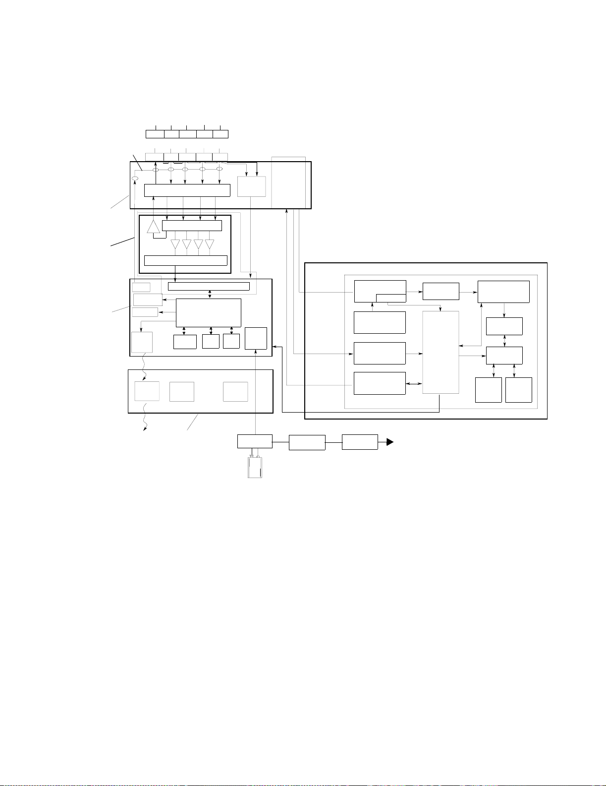
The Transmitter consists of the following assemblies. See Figure 1-1.
•ECG Leadset
• SpO
Transducer
2
• Front-end Assembly
• Case Assembly
• ECG Printed Circuit Board (PCB)
• Main Digital PCB, which contains the following subsections:
a. digital section
b. RF section, including the synthesizer
c. power supply
• SpO
• SpO
PCB
2
Transducer
2
•Battery
• Battery extender
1-4 Introducing the Philips Telemetry System
Page 19
Transmitter
RF Connected to
Leadset Shield
Front
End
Assembly
RF
Cable
Main
PCB
Ref.
S
RL
LA
Defibrillator Protection
Lead Sel.& Calibration
A to D Converter (Analog Portion)
RF Out
Frequency
Synthesizer
Modulator
SIR
Interface
Window
A to D Converter (Digital Portion)
EEPROM
Lead Off
IR
LEDS
I
RA
ECG PCB
Digital
ASIC
RAM
EASI Leadset
E
ECG Leadset
V
Leadset
Detect
Switch
DSP
Patient
Button
Power
Supply
SpO
2
Connector
and
Gasket
SpO2 Transducer
Photo Current
Rtype/Rlambda
LED Current
Photo Amplifier
Clip Output
Selftest Signal
Generator
RCode
Measurement
LED Driver
Bandpass
MAIN - CPU
SpO2 PCB
Variable Gain
ADC
ASIC
Pierce
Osc.
Digital
Signal
Processor
A
LL
Case
Assembly
Battery
Contacts
Cradle
PWR
Module
Wall
Receptacle
Figure 1-2 Block Diagram of Philips Transmitter
Leadsets The standard ECG system supports two leadset configurations: 3-wire and 5-
wire. With a 3-wire leadset, only 1 lead is transmitted (lead II is the default),
and leads I, II, or III can be selected if the transmitter is configured for 3-wire
leadset selection. For EASI, a 5-wire leadset is required.
The ECG leadset provides connection from the inputs of the transmitter to the
electrodes on the patient. Each lead has its own front end circuitry in the
transmitter that routes the signal from each lead to the transmitter’s
processing circuits. The transmitter sources an active lead for each
connection. Each signal is then combined to generate the transmitted leads.
3-Wire Leadset
(Standard ECG)
The 3-wire leadset broadcasts one lead (lead II is the default) of ECG for
display at the Central Station. The selection of leads for display using the 3wire leadset are determined by whether the lead selection function is
enabled (
Yes) or disabled (No - factory default) in the transmitter
configuration.
Introducing the Philips Telemetry System
1-5
Page 20

Transmitter
Lead Selection Enabled - With lead selection enabled, the cardiotach
lead, which is broadcast, can be selected using the Telemetry Service
Tool or Wave Viewer. In this mode, the broadcast lead can be selected
from Leads I, II, or III. The lead label is automatically changed at the
Central Station when the lead is changed.
Lead Selection Disabled (Factory Default) - When lead selection is
disabled, the broadcast lead is set at Lead II. The only way the lead can
be changed is by changing the electrode placement on the patient to a
non-standard configuration. When doing this, place the leads that
normally monitor lead II over the limb lead to be monitored. This means
that Leads I, II, III, or MCL can be monitored; however, the central
station will still display Lead II. The lead label must also be changed at
the Central Station to the lead being broadcast.
5-Wire Leadset
(Standard ECG)
With the 5-wire leadset, 3 leads are broadcast: II, III, and MCL. From these 3
leads, the software in the receiver mainframe can reconstruct the remaining 5
leads: I, aVR, aVL, aVF, and a true V lead. The leads to view can be selected at
the Central Station.
5-Wire Leadset
(EASI ECG)
When the transmitter is configured for monitoring the 12-lead EASI ECG, a 5wire leadset must be used. The 3 directly acquired or “raw” EASI leads (AI,
AS, ES) are broadcast by the transmitter. Software in the Philips Information
1
2
3
4
5
Center mathematically reconstructs the following leads: I, II, III, aVR, aVL,
aVF, V1, V2, V3, V4, V5, V6, and will perform arrhythmia analysis on 2 of the
leads and ST analysis on all 12.
EASI
If monitoring is attempted with a 3-wire leadset attached to an EASI ECG
transmitter, the system will report an
message (INOP) at the central station.
SpO2 Transducer When SpO
processed by a dedicated SpO
parameter values are sent as part of the broadcast.
Front End Assembly
The Front End Assembly the Transmitter is where the ECG Leadset and the
Transducer plug in. It contains the following features:
SpO
2
1. Leadset detect switches that identify which leadset (3- or 5-lead) is
connected to the transmitter and sends the information to the digital
ASIC on the Main PCB. The leadset detect switches are positioned next
to the RL and V lead wires in the standard ECG configuration, or next to
the Reference and E lead wires in the EASI configuration (the two
connector cutouts are rectangular not square).
2. High impedance resistors that provide defibrillator protection to the
signal acquisition circuits on the ECG PCB.
3. Radio Frequency (RF) cable connection to the leadset shield that
allows the RF signal to be transmitted through the leadset, which acts as
an antenna.
INVALID LEADSET inoperative
is monitored, the data are received via a SpO2 Transducer,
2
circuit within the transmitter, and the
2
1-6 Introducing the Philips Telemetry System
Page 21

Transmitter
Case Assembly The Case Assembly provides protection to the internal electronics of the
transmitter. It also contains the nurse-call button and the leads-off Light
Emitting Diodes (LEDs).
Transmitter Button The Transmitter Button is a membrane switch that toggles a bit in the
transmitted message to ON when the switch is pressed. Electrically, the
transmitter button has two positions:
OFF (not pressed)
ON (pressed)
The Transmitter Button can be configured in the receiver mainframe to
perform the following actions when it is pressed:
1. generate a yellow-level nurse call alarm at the central station
2. generate a recording at the central station
3. generate both a nurse call alarm and a recording at the central station
4. do nothing
Once the alarm or recording has been started, it can only be stopped at the
central station. Pressing the button on the transmitter again does not affect
the alarm or the recording.
Manual SpO
Measurements
Even if the transmitter button is configured for DISABLED or if the button is
2
turned
OFF at the central station, Manual SpO
Transmitter button are still possible.
If a transmitter is set for intermittent SpO
measurements (manual mode, 1
2
minute and 5 minutes), manual measurements from the transmitter can be
initiated at any time using the transmitter button or Wave Viewer. SpO
be turned on at the central station for alarms and for display and trending.
Note If the transmitter is in manual mode, the SpO
will turn on automatically when a measurement is initiated. If the transmitter
is in the 1-minute or 5-minute sample mode, SpO
central station by the user.
To initiate a Manual SpO2 Measurement at the transmitter, do the following:
• Plug the transducer cable into the transmitter.
• Attach the transducer to the patient.
• Press and hold the transmitter button (approximately 6 seconds) until
the LA light for standard ECG (S light for EASI ECG) begins flashing.
When the transducer light turns off, the measurement is complete.
• Remove the transducer from the patient after the transducer light goes
out. The measurements value and time stamp will be displayed at the
Central Station for up to 1 hour or until the next measurement is made,
whichever comes first.
Measurements using the
2
must
2
parameter at the central station
2
must be turned on at the
2
Leads Off LEDs A Leads Off Light Emitting Diode (LED) turns on whenever one of the
leads falls off the patient, or if the circuitry for that lead is defective. There is
one LED for each electrode, and they are shown in the electrode placement
diagram on the transmitter in the standard lead placement.
Introducing the Philips Telemetry System
1-7
Page 22

Transmitter
ECG PCB The ECG Printed Circuit Board (PCB) contains the ECG Front-end
Circuitry, which acquires the ECG signal from the leadset. This circuitry
provides basic preamplification of the signals, filters the signals, then
performs the first stage of analog-to-digital conversion.
The output circuit of the reference drive sums the outputs of the four other
electrode inputs to generate one output that is used for improving common
mode rejection performance. The reference drive output can be switched to
drive any of the four input electrodes.
The Front-end Circuitry for each input electrode does the following:
• acquisition and preamplification of ECG signal
• bandpass filtering and conditioning of the signal
• Initial analog-to-digital conversion of the ECG signal
Each Analog-to-Digital Converter consists of the following subcircuits:
• input buffer amplifier
• low frequency summing amplifier
• integrating analog-to-digital converter
The circuitry for each electrode is the same. Resistors of the input buffer
amplifier provide input protection for the front end ICs. An operational
amplifier sets the noise performance of the incoming ECG signal by filtering
out unwanted noise on the input leads. A low frequency feedback summation
amplifier provides preamplification and further conditioning of the incoming
ECG signal. The final stage of the analog section is a pulse width modulated
A/D converter. This is the first stage of the analog-to-digital conversion of the
ECG signal. The second stage takes place on the Main PCB.
Main PCB The Main PCB contains the main processing and signal transmitting circuits
for the transmitter. The Main PCB can be broken into 3 functional areas:
• Digital Section
•RF Section
• Power Supply
Digital Section The Digital Section of the transmitter consists of a digital ASIC, digital signal
processor (DSP), and memory. The digital ASIC consists of a gate array,
which provides interfaces to the DSP from the following circuits:
•ECG PCB
• 3/5 wire leadset switch
• nurse-call button
• Leads Off LEDs
• SpO
• Serial infrared (IR) port to Wave Viewer
• Control lines for the frequency synthesizer
• RF output circuit
• Power Supply control
• Memory Section
circuits
2
1-8 Introducing the Philips Telemetry System
Page 23

Transmitter
The gate array consists of latches and logic control gates that control the flow
of information to the DSP. The DSP then processes the signal from each
interface and includes it into the transmitted message. The following
paragraphs describe each interface controlled by the gate array and processed
by the DSP.
ECG PCB Interface The ECG PCB Interface is a gate array that receives the output for each of
the 4 input electrodes and routes the signal to the DSP for the following
processing:
• Final analog-to-digital conversion of each lead signal.
• Checks for Leads-Off conditions
• Processing of the leads to be transmitted
• Pace pulse detection and processing
Lead Set Detect
Circuit
A Lead Set Detect Circuit in the Transmitter senses whether a 3-wire or 5-
wire leadset is being used. The transmitter has 2 pressure sensitive switches
that change from high impedance to low when an RL or V lead wire (standard
ECG leadset) or a Reference or E lead wire (EASI leadset) is inserted into the
connector.
Note When replacing patient leadsets, it is very important to connect them properly.
An incorrect connection can cause the transmitter to detect the wrong leadset
.
Transmitter Button The Transmitter Button on the Case Assembly has a direct connection to
the Digital Section of the Main PCB. Refer to the previous section or the
Instructions for Use for the Central Station for more information on the
transmitter button.
Leads Off LEDs Leads Off LEDs on the Case Assembly indicate when the leads are properly
connected to the patient. When the leads are properly connected, the LEDs
are off. When the Digital Section of the Main PCB senses a lead off condition,
it turns on the appropriate LED on the Case Assembly via a direct line.
In general, when the transmitter is on a patient or a simulator, a Leads Off
LED will light to indicate that a lead wire is not connected. However, there
are some subtleties in operation that may raise some questions for the service
provider. The LED that is on depends on several factors: if a leadset is
attached, which type of leadset is attached, how Lead Selection for a 3-wire
leadset in the transmitter is configured and which electrode wire is off.
There are 2 switches in the transmitter where the leadset plugs in. If the 2
switches are closed, the transmitter knows that a 5-electrode leadset is
attached to the transmitter. If they are open, the transmitter will respond as if
a 3-electrode leadset is attached. Note that the transmitter cannot distinguish
between a 3-electrode leadset and no leadset. For this reason, if no leadset is
attached, the LEDs will react as if the transmitter has a 3-electrode leadset
attached.
Introducing the Philips Telemetry System
1-9
Page 24

Transmitter
Knowing which electrode is the reference electrode is important for
understanding how the LEDs work, and the reference electrode depends on
which leadset is attached to the transmitter. If a 5-electrode is attached, the
RL (standard ECG) or the Reference (EASI) electrode is always the reference
lead.
If a 3-electrode leadset is attached, the reference electrode depends on which
lead is being measured by the transmitter.
Lead Selection in the transmitter is configured to NO (factory default),
When
the transmitter always measures lead II. Lead II is the voltage across the right
arm and left leg (RA-LL) electrodes. This leaves the left arm (LA) as the
reference electrode.
When
Lead Selection in the transmitter is configured to YES, then the lead
being measured can change and, as a result, the reference electrode can
change.
Table 1-1. Reference Electrode for 3-Electrode Leadset with Lead
Selection Configured for YES
Selected
-+Reference
Lead
IRALALL
II RA LL LA
III LA LL RA
Which LED lights also depends on which electrode wire is off. If the wire for
the reference electrode is off, only the reference electrode LED will be on –
even if multiple electrode wires are off. If the wires for any other electrode or
combination of electrodes are off, those LEDs will be on. There is one
exception to this. If all the electrode wires except for the reference electrode
are off, the transmitter cannot distinguish between this situation and the
reference electrode wire being off. In this situation, only the reference
electrode LED will be on.
From a user perspective, using the LEDs is simple:
• Attach the electrode wire(s) indicated by the LEDs on the transmitter
• Check the transmitter LEDs again
• If additional LEDs are on, attach the electrode wires indicated
• If a LED is on, and that wire is attached, then all of the other electrode
wires must be off.
Serial Infrared Port The transmitter communicates to the TeleMon and Telemetry Configuration
Tool via the Serial Infrared Port (SIR). This port connects to the DSP via a
3 wire UART.
Power Supply Control The transmitter monitors the operation of the power supply and controls its
operation as appropriate. The digital section of the transmitter performs the
following Power Supply Control functions:
1-10 Introducing the Philips Tele me try Sys tem
Page 25

Transmitter
Battery type sensing - The transmitter works with 8.4- and 9-volt batteries
(alkaline, zinc-air, and lithium) except when SpO
is being used.
2
Caution When using SpO
battery is used with SpO
BATTERY
If a
INOP are sent to the Central Station.
BATTERY WEAK message occurs, no SpO
communication can occur, but the ECG functions normally.
REPLACE BATTERY message occurs, all functions cease.
If a
Low Voltage and Replace Battery Circuit - If the battery voltage falls
below 6.6 volts, a battery weak signal is generated and transmitted to the
central station as an INOP. If the voltage falls below 5.9 volts, the replace
battery signal is generated and sent to the central station as an INOP.
Memory Section The Memory Section consists of a serial EEPROM, which stores the program
for the DSP. The program is loaded at power-up using a small set of
instructions contained within the ASIC. The DSP runs the program out of
internal DSP RAM. The EEPROM stores several variables so that
configuration information is kept when the battery is removed. The external
RAM is used as a communication buffer area.
RF Section The RF Section is a programmable frequency synthesized local oscillator
operating at ultra-high frequency. A temperature compensated crystal
oscillator provides the reference frequency. The digital bit stream from the
DSP is used to modulate the carrier frequency. These data are applied to the
synthesizer voltage controlled oscillator (VCO). The VCO output drives a
common-emitter bipolar transistor output stage. The output stage filter
provides spurious filtering and transforms the 50 Ohm nominal impedance of
the antenna circuit to present the optimum impedance to the output stage
collector for high efficiency. The shielded cable of the ECG lead set serves
as the broadcast antenna for the transmitter.
, zinc-air batteries cannot be used. If a zinc-air
2
, frequent BATTERY WEAK and/or REPLACE
2
or TeleMon
2
The transmitter frequency can be changed or set using the Telemetry Service
Tool or TeleMon.
Power Supply The Power Supply provides all of the voltages for use by the transmitter. It
consists of 2 linear low dropout regulators of 3 and 5 volts. This provides the
5V and 2.5V needed for the operation of the transmitter. Power to the
regulators is derived from an 8.4- or 9-volt battery. To protect against battery
reversal, power for the battery is delivered to a pair of back to back
MOSFETs.
Comparators sense and warn of low and replace battery conditions via the
power supply control circuitry of the digital section. The replace battery
indication is sent to the DSP to control shutdown so that the necessary
housekeeping and replace battery message can be transmitted prior to
shutdown.
Introducing the Philips Telemetry System
1-11
Page 26
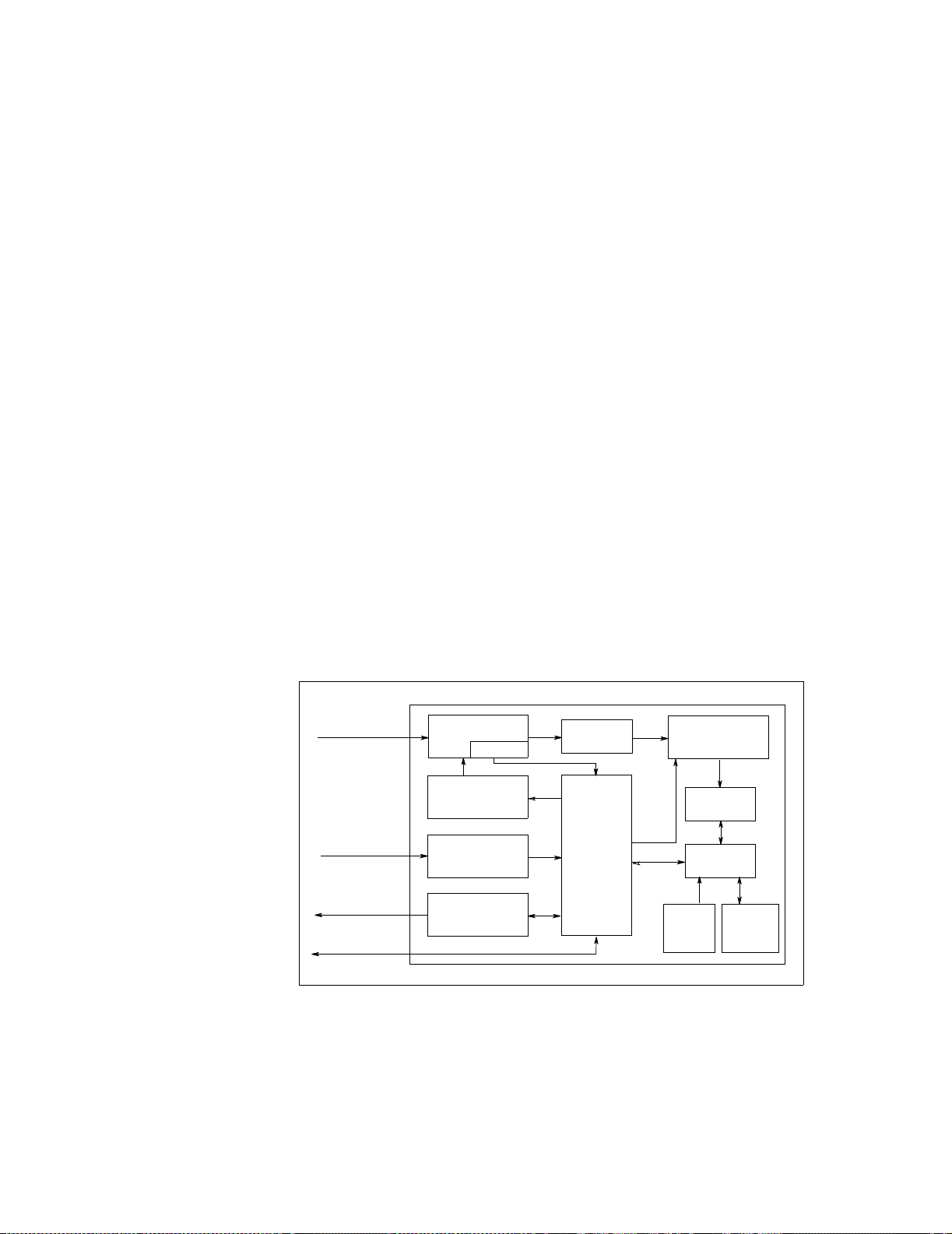
Transmitter
SpO2 Module The SpO
attaches to the patient’s finger, and a SpO
Module of the transmitter consists of an SpO2 Transducer, which
2
Board.
2
SpO2 Transducer The SpO2 Transducer measurement is based on the phenomenon that
oxygenated blood has different absorption in red and infrared light
wavelengths, related to the oxygenation of the blood.The red and infrared
LEDs in the SpO
sensor emit light, which is detected by a photo diode after
2
passing through the patient’s skin. The received signal is analog and digitally
processed, which yields a pulsatile raw wave for the red and infrared
absorption.
SpO2 Board The SpO
algorithm that calculates SpO
representation for the given raw wave. The red and infrared LED signals are
o
90
Board is shown in Figure 1-3. It contains a Main CPU with an
2
, pulse rate and perfusion value in numeric
2
out of phase. At the receiving Photo Diode, the sum of the signals is
analog processed and digitally demodulated. This method, based on the
theory of quadrature modulation, produces signals that are highly resistant to
noise (ambient light) and consumes less power than other methods.
Photo Amplifier
The transducer routes the input current from the photodiode to the Photo
Amplifier. The Photo Amplifier performs the following functions:
• Converts the input currents to output voltages
• First order, low bandpass filters the input signals to eliminate incoming
disturbances of higher frequencies.
SpO
Board
2
Photo Current
from Transducer
Rtype/Rlambda
LED Current
Transmitter Interface
Photo Amplifier
Clip Output
Selftest Signal
Generator
RCode
Measurement
LED Driver
Bandpass
Main
Processing
CPU
Variable Gain
ADC
ASIC
Pierce
Osc.
Digital
Signal
Processor
Figure 1-3 SpO2 Board Block Diagram
The Photo Amplifier is implemented as a differential amplifier to provide
balanced input characteristics and to suppress incoming disturbances.
1-12 Introducing the Philips Tele me try Sys tem
Page 27

Transmitter
A clipping detection circuit is connected to the output of the Photo Amplifier
and serves as a controlling stage for the Photo Amplifier. By using a
comparator connected as an inverting Schmitt Trigger, clipping of the Photo
Amplifier signal caused by ambient light (for example) is detected. The output
of this stage is connected to the front end controlling firmware of the Main
CPU to generate an INOP alarm in case of excessive clipping. The comparator
circuitry contains a hysteresis loop to avoid jittering of the output signal.
Bandpass Filter
The modulated signals coming from the photo amplifier pass through a third
order Butterworth Bandpass Filter. This serves as an anti-aliasing filter and
filters out all disturbance frequencies outside a passband centered on the
modulation frequency.
Variable Gain Amplifier and Analog to Digital Converter (ADC)
The Variable Gain amplifier augments the signal from the bandpass filter
and routes the signal to the Analog to Digital Converter (ADC). The
output of the ADC is sent to the digital ASIC.
ASIC
The digital ASIC works as an interface between the DSP and the main
processing CPU. In addition, the digital ASIC acts as an interface to the ADC
and contains all frequency generators for the ADC clock, the sampling
frequency, and the modulation frequency and the necessary glue logic.
Digital Signal Processor (DSP)
The Digital Signal Processor (DSP) communicates via the digital ASIC
with the ADC and main processing CPU. It demodulates and filters the
incoming ADC signals and transmits the output signals to the main processing
CPU.
Main Processing CPU
The Main Processing CPU performs the processing for the SpO2 signals. It
communicates via the digital ASIC with the DSP and contains the front end
controlling firmware for the LED driver circuit, the RCode measurement
circuit, the variable gain stage, the clipping detection, the power supply, and
the self-test circuit. The main processing CPU also provides a communication
interface to the transmitter controller.
LED Driver
The LED Driver circuit generates the LED current using two transistor
current sources receiving a constant voltage input from the power supply. A
bridge consisting of four transistors allows the LED current to be switched
alternatively for individually driving the red and infrared LEDs of the sensor.
To enable the different driving times of the LEDs, the main processing CPU
controls the transistors in the bridge.
Introducing the Philips Telemetry System
1-13
Page 28

Transmitter
Self-Test Circuit
The Self-Test Circuit performs a self-test of the SpO2 measurement device
before patient signal processing begins. The Main Processing CPU produces a
pulse-width modulated signal which is analog low pass filtered to a sine wave
and converted to a photo current signal. During self-test, the connections of
the photoamplifier to the photodiode of the sensor are interrupted by
switches and the self-test signal is fed into the input of the Photo Amplifier.
RCode Measurement Circuit
The RCode Measurement Circuit identifies which sensor is being used by
measuring coding resistors. The Main Processing CPU reads the measurement
through a reference resistor and an amplifier stage.
Battery Extender The Battery Extender consists of a cradle, which is fitted over the battery
compartment of the transmitter, and a cable connecting to a wall-mounted dc
power module.
When the battery Extender is in use, the transmitter is being powered by the
wall mounted dc power module. If the cradle is disconnected, the power will
immediately power the transmitter and the electrical unit ceases to power the
transmitter.
Note The purpose of the Battery Extender is to conserve battery life.
The Extender does not recharge the battery.
1-14 Introducing the Philips Tele me try Sys tem
Page 29

Receiver Mainframe
Receiver Mainframe
The Receiver Mainframe provides the physical interface between the
receiver module and the central monitoring station via the Serial Distribution
Network (SDN). The receiver mainframe houses up to 8 receiver modules,
each one frequency-matched to a transmitter.
A BNC connector on the mainframe is used to connect to the antenna system
output. The BNC connector is connected to the antenna distribution board,
which distributes the combined RF signal to each receiver module. The
receiver modules receive incoming RF signals via a semi-rigid RF cable
connected to the antenna distribution assembly. The receiver modules plug
into the receiver backplane, which provides an interface to the internal power
supply and the digital backplane. The digital backplane provides interface to
the digital cardcage, which houses the signal processing and distribution
circuits.
For a standard ECG channel, the receiver mainframe calculates the heart rate
from the user-selected primary ECG lead and sends the result, with the ECG
wave information and any alarms, INOPS, and status information, over the
SDN. The mainframe also provides lead reconstruction, gain adjustment, and
filtering.
For an EASI channel, the receiver mainframe reconstructs Lead II information
from the three directly acquired or “raw” EASI lead outputs sent by the
transmitter (AI, AS, ES) and sends this information out on the SDN for
overview purposes. The mainframe also sends the 3 “raw” EASI leads to the
Philips Information Center (PIC) over the SDN.
The Philips Information Center (PIC) reconstructs the 12-lead EASI ECG lead
information and performs all ECG analyses and alarms. The PIC detects
arrhythmia and ST inoperative conditions and generates messages. The
mainframe sources all other INOPs detected by the telemetry system (Leads
Off, battery, SpO
The processing and distribution circuits of the receiver mainframe consist of
the following components:
• Rack Interface
• Utility CPU
• 40 MHz configurable processor card (CPC)
• SDN Board
In addition to the 8 receiver module malfunction LEDs, the receiver
mainframe has a separate mainframe malfunction LED. The mainframe
malfunction LED is visible through a hole in the front dress cover and
illuminates to indicate a malfunction has occurred within the mainframe.
Cooling for the internal assemblies of the receiver mainframe is provided by a
dc fan. The fan operates on 12V dc from the power supply via the receiver
backplane.
equipment malfunctions, etc.) on the SDN.
2
Introducing the Philips Telemetry System
1-15
Page 30
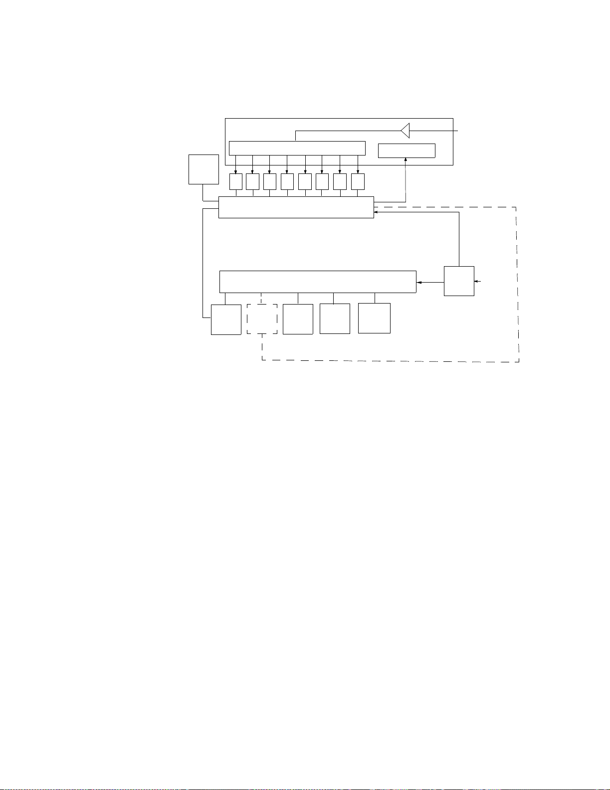
Receiver Mainframe
FE
Link
Fan
Antennas Distribution Board
Rack
Interface
1 - 8 Splitter
RRR R2R
Receiver Back Plane
Digital Backplane
Analog
Output
(optional)
Utility
CPU
SDN
Interface
RF Amplifier
Malfuction LEDs
1876R5R4R3
CPC
Card
1 Mainframe
8 Receiver Modules
+12Vdc
5Vdc
+12Vdc
5Vdc
Power
Supply
RF from
Antenna
System
Incoming
Line
Voltage
Figure 1-4 Block Diagram of Philips Receiver Mainframe
Power Supply The Power Supply is an auto switching power supply with the following
specifications:
Input Voltage: 100 - 240 Vac
Input Frequency: 47 to 63 Hz.
Power consumption (for M2604A with 8 M2603A receiver modules:
110 VA max, 95 VA average
81 W max, 72 W average
Radiated Immunity: 3 Volts/meter outside of operating receiver bands
The power supply generates two logic signals:
• SR (system reset) at start up
• PF (power fail) during power shut down
Antenna Distribution Assembly
The Antenna Distribution Assembly distributes the RF signal received
from the external antenna system to each receiver. The external antenna
connection to the receiver mainframe is made through a single BNC
connector on the rear panel, through the internal antenna cable, and
connected to the Antenna Distribution Assembly. An RF amplifier increases
the incoming RF signal. A low loss 1-to-8 splitter follows the amplifier. It
distributes the received RF signal to each receiver module.
The Antenna Distribution Assembly also contains a digital section consisting
of 8 receiver malfunction LEDs, 1 power-on LED, and a watchdog circuit that
drives the mainframe malfunction LED. A logic pulse train from the rack
interface resets the watchdog timer. If greater than 600 msecs elapses
between receipt of pulse trains, the watchdog timer output illuminates the
mainframe malfunction LED.
1-16 Introducing the Philips Tele me try Sys tem
Page 31

Receiver Mainframe
The 8 LEDs indicate malfunctions that may occur in the receiver mainframe.
Each receiver module slot (1 through 8) has a malfunction LED associated
with it. The LEDs are located on the antenna distribution board. They are
visible on removal of the front dress cover.
When an LED is not illuminated, the receiver module is not recognized by
the mainframe.
When an LED is flashing at a rate of once per second, the receiver module
for that LED is receiving and working properly.
When an LED is flickering at a rapid rate, the receiver module cannot find
a good signal.
When an LED remains illuminated steadily, this indicates a malfunction
has been detected in the receiver module corresponding to that LED.
Receiver Backplane
The Receiver Backplane provides the interfaces between the receiver
modules, the power supply, receiver malfunction LEDs, and digital section of
the mainframe. It provides connections from the 8 receiver modules to the
rack interface using the front-end high-speed serial link (FE-LINK). The FELINK serves as an 8-to-1 multiplexer, which allows sequential communication
between the rack interface and each receiver.
Digital Backplane The Digital Backplane consists of one 9-pin connector and nine 96-pin
connectors. The 9-pin connector interfaces the power supply with the digital
backplane. The receiver mainframe PCBs plug into the 96-pin connectors
creating a multiprocessor system consisting of the Utility CPU and the CPC
Processor. The CPC processor card and the Utility CPU communicate with
each other by exchanging messages, but do not have access to each other’s
memory.
The message passing architecture can be split into 3 logical parts or busses:
• Message Passing Bus (MPB)
• Local Bus
• Utility Bus
The Message Passing Bus is the global communications bus for the receiver
mainframe, and is used for communications between the CPUs and intelligent
interface PCBs.
The Local Bus is used for data transfer among the Utility CPU, SDN interface,
and rack interface.
The Utility Bus routes power and clock functions to the PCBs connected to
the backplane.
Rack Interface The Rack Interface provides communication between the CPC processor
card, via the Utility CPU, and the 8 receiver modules. It acquires serial data at
500 Kbaud and status from the receiver modules and sends control signals to
them using the FE-Link. The Rack Interface polls the receivers in the receiver
mainframe as to their status. It uses this information to control the logic pulse
train to satisfy the watchdog timer on the antenna distribution assembly. If a
malfunction occurs in a device in the receiver mainframe, the pulse train is
inhibited, causing the watchdog timer to trigger the mainframe malfunction
LED.
Introducing the Philips Telemetry System
1-17
Page 32

Receiver Mainframe
The Rack Interface transfers data internally using a switched RAM method.
Two banks of switched RAM are used alternately by the on-board 8051
microprocessor and the 68000 microprocessor on the Utility CPU. Every 32
ms the RAMs are switched, so the RAMs can be accessed by the other
microprocessor. This allows the faster 68000 microprocessor to exchange
data with the RAM and then run on before the RAMs are switched. The 8051
microprocessor then converts the data into serial data for passing to the
receiver modules over the FE-LINK. Received serial data from the receiver
modules are converted to parallel data and placed into RAM by the 8051
microprocessor. The RAMs are then switched, allowing the Utility CPU to
exchange data again.
Configurable Processor Card
The Configurable Processor Card (CPC) is a CPU card that is used to
process the application data for the mainframe. The CPC receives data from
the Message Passing Bus (MPB), processes the data, and places the results of
the data processing back on the MPB.
The CPC contains the following functional areas: a 68030 Microprocessor,
MPB Interface, a Flash ROM, DRAM, Fast SRAM, Buffered SRAM, Interface,
and Service Port. The CPC CPU is based on the 68030 Microprocessor chip.
This is the interface between the CPC and the MPB.
The Flash EPROM contains the operating software. The Flash EPROM is
programmed using the CPC programming tool. The EPROM normally has VPP
set low (between 4.0V and 4.5V) and functions as read-only memory. The tool
operates by setting VPP high (12V) and writing an appropriate instruction to
the EPROM.
The DRAM is used for 2 purposes -- to download programs from the flash
EPROM for faster execution and to provide unbuffered storage for
applications. The DRAM is configured as two 32 bit wide banks of 1 MB each.
The Fast SRAM is used primarily for program execution speed enhancement.
The Fast SRAM is configured as one 32 bit wide bank.
The Buffered SRAM stores application data in the event of a power failure.
The Buffered SRAM is configured as 1, 32-bit wide (512 Kbytes) bank and 4, 8bit wide (256 Kbytes) banks. All banks are backed up by a super-capacitor to
provide a minimum of three hours of storage.
Utility CPU The Utility CPU is responsible for the rack and SDN interfaces,
synchronization, and all of the clock signals for the receiver mainframe. The
Utility CPU is based around a 68000 microprocessor and stores the
configuration of the receiver mainframe on an 8-Kbyte EEPROM.
SDN Interface The SDN interface provides the interface between the CPC processor card,
via the Utility CPU, and the Serial Distribution Network (SDN). The SDN
interface transmits and receives data to and from the SDN over a 2-wire bus.
The SDN polls the SDN interface every 32 ms. The poll cycle is divided into 4
ms dead time and 28 ms for passing data to and from the receiver mainframe.
The onboard RAM consists of 2, 2 Kb buffers -- 1 transmit, 1 receive. During
the dead time, the Utility CPU places all data into the transmit half of the SDN
interface onboard RAM. An SDN interface circuit chip (SIC) chip on the SDN
1-18 Introducing the Philips Tele me try Sys tem
Page 33

Receiver Mainframe
interface sends the data over the SDN during the 28 ms communication
period. Received data are placed in the receive half of the onboard RAM
where they are read by the Utility CPU during the dead time.
Patient Monitor/ Holter Recorder Interface (Analog Output)
Note Because EASI ECG requires the 3 directly acquired or “raw” EASI leads (AI,
The Patient Monitor/Holter Recorder Interface (Analog Output Option)
creates analog signals that can be used to drive the ECG level inputs of
bedside monitors or Holter recorders. The hardware limits the number of
output leads to 2.
When a 3-electrode leadset is used on a standard ECG transmitter, only lead II
is available.
When a 5-electrode leadset is used, only lead II and MCL is available.
AS, ES), the Patient Monitor/Holter Recorder Interface is not
compatible with channels using EASI transmitters.
Digital data, in the form of a serial data stream, are acquired from the FE-Link
at 500 Kbaud. The stream contains status information for all 8 receivers as
well as digitized ECG signals. The data stream is decoded at the analog output
board and converted to analog voltages at again 500 times the original signal
level.
An external breakout box then splits the signal into 8 output pairs, which are
placed on individual patient jacks to provide 1 bedside monitor and 1 Holter
recorder output for each receiver module. The bedside and Holter output
circuitry attenuates the signals back to ECG levels.
INOP flags from leads-off, replace battery, and data invalid conditions are
encoded as voltage levels onto each analog output signal, causing the signal at
the bedside Holter output circuitry to assume a very high impedance that is
interpreted by the monitoring device as a
circuit also forces all outputs to a
is lost or if there is a malfunction in the analog output system.
LEADS OFF condition if mainframe power
LEADS OFF. A separate fail-safe
Pace pulse flags sent with the data stream cause the analog output system to
create a synthesized pace pulse of fixed amplitude and duration. The system
analyzes the ECG data surrounding the flags to determine and to match the
original polarity of the pace pulse. The duration of the synthesized pace pulse
is intentionally made very short so it will be detected by the bedside monitor,
but will not disturb the arrhythmia monitoring system.
Introducing the Philips Telemetry System
1-19
Page 34

Receiver Module
Receiver Module
The Receiver Module is housed in the receiver mainframe. Each receiver
module is dedicated to a specific transmitter. It receives the UHF data
transmission from the transmitter and converts the serial data stream into a
format that can be transferred through the receiver backplane to the receiver
mainframe. The receiver can handle information from either a standard ECG
transmitter or an EASI ECG transmitter. The receiver module consists of two
basic sections:
• RF section (including the tunable synthesizer)
• digital baseband section.
RF
Input
(50ohm)
RF
Bandpass
Filter
RF Section
PLL Freq. Synthesizer
1st Loca l O s c illa t or
Freq. Range depends on option
Receiver PCB
1st IF
(21.4MHz)
AFC
Synthesizer Control
MixerMixer
2nd LO
20.945 MHz
Detector
Digital Baseband Section
2nd IF
(455kHz)
Receiver
Processor
Figure 1-5 Block Diagram of Philips Receiver Module
RF Section The RF Section of the receiver module receives the UHF digital data
transmission, down-converts and demodulates it, and then routes it to the
digital baseband section as a serial data stream.
The receiver module is a dual-conversion, narrow-band frequency modulation
(FM) receiver. It takes the incoming RF signal (for example, 460 MHz), mixes
it with a local oscillator frequency (481.40 MHz) to generate an intermediate
frequency (IF) of 21.40 MHz.
The IF is filtered and amplified several times and then mixed with a second
local oscillator frequency (20.945 MHz) to generate the second IF at 455 KHz.
The second IF is filtered and amplified several times and then demodulated.
Data
Output
Power
Frequency
Synthesizer Section
The Receiver Frequency is determined by the tunable RF module used to
generate the first local oscillator frequency. The RF module circuitry is the
same as that of the transmitter RF module.
In a system that operates between 406-480 MHz the receiver is tuned to the
same frequency as the transmitter. Within a system that operates in the
extended UHF band (590-632 MHz) the receiver is tuned to:
Receiver Frequency = Transmitter Frequency - Converter Frequency Shift Option
1-20 Introducing the Philips Tele me try Sys tem
Page 35

Receiver Module
The Frequency Synthesizer is essentially a non-linear control system using
a single narrow bandwidth loop to achieve low phase noise for good system
adjacent channel rejection performance. The phase detector output drives the
loop filter and the control port of a voltage controlled oscillator (VCO).
The Loop Filter controls all aspects of system performance. The phase
detector drives both its inputs to zero phase error, so the VCO output
frequency is locked to the reference frequency.
The Phase Detector derives its input from a temperature compensated
crystal (TCXO) reference and a sample of the output VCO frequency.
Programmable dividers separate the VCO output frequency before it is fed
back to the phase detector.
The Programmable Divider allows incremental frequency control of the
final VCO frequency. The design of the synthesizer allows frequency steps of
5kHz, 10kHz, or 12.5kHz.
Digital Baseband Section
Detector The Detector performs the basic conversion of the input serial data stream
Microcontroller The serial data stream output from the detector goes to the Microcontroller
The Digital Baseband Section converts the serial data stream detected by
the RF Section into data suitable for transfer through the receiver backplane
to the receiver mainframe. The conversion includes bit clock recovery, frame
synchronization, unscrambling, error detection, unpacking and expansion of
compressed data.
The Digital Baseband Section also supplies an Automatic Frequency Control
(AFC) voltage to fine-tune the local oscillator of the RF section. The digital
baseband section can be split into 3 functional parts:
•Detector
• Microcontroller
• Peripheral Devices
into digital data readable by the microprocessor. The bit pattern first passes
through an RF filter, which ensures that digital noise generated in the digital
baseband section is not coupled into the shielded RF section. The Detector
then synchronizes where the bit cells (ones and zeros) are in the digital bit
pattern and determines whether a one or zero was sent in each cell.
where it is manipulated and processed into separate data items contained in
the serial data stream. This is where the unscrambling, unpacking, error
detection, and expansion of the compressed data happens. The serial data are
transferred to the Receiver Backplane of the Receiver Mainframe. The
Microcontroller also provides control signals to the peripheral device and a
signal to the board failure line.
Peripheral Devices An Analog-to-Digital Converter and Digital-to Analog Converter are interfaced
to the Microcontroller to provide Automatic Frequency Control (AFC) to the
RF section and received signal strength measurement
Introducing the Philips Telemetry System
1-21
Page 36

M2613/14/15A Dual-Band UHF Antenna System
E
R
R
D
R
M2613/14/15A Dual-Band UHF Antenna System
The M2613/14/15A Dual-band UHF Antenna System receives RF signals
from transmitters in the coverage area broadcasting between 406-632 MHz.
Antenna Systems consist of Antenna Strings and Combining Networks as
shown in
Figure 1-6.
Dual Band Antenna System Signals received at 462, 464, 612 and 613 MHz
Antenna
Standard Band
Transmitters
AB C D
Signals Broadcast
at 462 and 464
MHz
Signals Broadcast
at 612 and 613
Strings
Extended Band
Transmitters
MHz
Combining
Network
Option C07
Frequency
Converter
Receiver Mainframe Receiver Mainframe
Standard Band Operation
Receivers:
A: Signal to be received = 462 MHz
Receiver tuned to 462 MHz
B: Signal to be received = 464 MHz
Receiver tuned to 464 MHz
Option C08
Signal shifted down in
frequency by 148 MHz
CDAB
xtended Band Operation
eceivers:
C: Signal to be received = 612 MHz
eceiver tuned to 612 - 148 = 464 MHz,
: Signal to be received = 613 MHz
eceiver tuned to 613 - 148 = 465 MHz
Receiver Mainframe
(Internal Frequency Converter)
D
C
Figure 1-6 Dual Band Operation
406 - 480 MHz Operation
For operation between 406 - 480 MHz, the signals are distributed directly to
the receiver mainframe. Inside the mainframe, the signal is distributed further
to the receiver modules, which are each tuned to receive one transmitters.
590 - 632 MHz Operation
For operation at the extended UHF frequencies, transmitters broadcast
signals at 590-632 MHz. These signals are received by the Antenna System
and go into a device that is called a Frequency Converter, which shifts or
“converts” the signal down in frequency. The converted signal is then fed into
the receiver mainframe, which distributes it further to the installed receivers.
Dual-Band Operation
A Dual-Band System can have channels operating in both bands. A
mainframe handling extended band frequencies will be attached to the
antenna system through a frequency converter, and a mainframe handling the
standard frequencies will tie directly to the Antenna System.
1-22 Introducing the Philips Tele me try Sys tem
Page 37

M2613/14/15A Dual-Band UHF Antenna System
Antenna Strings Antenna Strings are available of 1 to 6 antennas (M2613/14A options A01-
A06). Each string consists of antenna/combiners and cables. Each Antenna
String receives the RF signal from each transmitter in the coverage area.
Combining Networks
Frequency Converter
Combining Networks combine signals from the Antenna Strings and
distribute them to the Receiver Mainframes or Frequency Converters.
Combining Networks consist of splitter/combiners, amplifiers, power tees,
and cabling. They supply the signal to each receiver module in the mainframe.
A Frequency Converter shifts or “converts” the signal from the Antenna
System down in frequency. The “shifted” signal is then fed into the receiver
mainframe, which distributes it to the installed receivers, which are tuned to
receive one of the transmitters. The Frequency Converter can be either
external (Option #C07) or internal (Option #C08) to the Receiver Mainframe.
Figure 1-7 shows a block diagram of a typical Antenna System.
dc RF
Antenna
String
#1
Antenna
String
#2
2 X1
Combiner
Line
Amp
Combining
Network
Receiver Mainframes
Power
Tee
Multiple Unit Power Supply
1 X4
Splitter
Frequency Converter
(Option #C07)
Receiver Mainframes
Power
Module
Receiver Mainframes
with internal
Frequency Convert er
(Option #C08)
Figure 1-7 Block Diagram of a Typical Antenna System
Introducing the Philips Telemetry System
1-23
Page 38

M2613/14/15A Dual-Band UHF Antenna System
M2608A Active Antenna/Combiner
The M2608A Active Antenna/Combiner incorporates a UHF quarter-wave
monopole antenna, a signal combiner, and an RF amplifier in one unit. The
amplifier has a bandpass range of approximately 406 - 650 MHz.
The Antenna/Combiner accepts 2 RF signals --1 from its flexible antenna and
1 from the line. The signals are coupled together in a Power Combiner,
amplified, and then cascaded to the next Antenna/Combiner in the string. At
the end of the string, the signal is routed to the combining network for final
signal combining and distribution to the receiver mainframe. A block diagram
of the antenna/combiner is shown in
Green
LED
Figure 1-8.
Line Input
(75 Ohms)
Combiner
Antenna Input
(Matched to
Antenna Whip)
Bandpass
Filter
Red
LED
GND
dc
Switching
dc Power Pass
and Direction Sense
4.5 V
Regulator
RF
Amp
Output
(75 Ohms)
Figure 1-8 Block Diagram of the Active Antenna/Combiner
The incoming RF signal from the antenna is sent through a Bandpass Filter
and coupled with the line signal in a Power Combiner. The Power Combiner is
unequal for reduced system noise figure and high 1dB compression point. The
2 signals are impedance-matched in the Power Combiner and routed to the
RF Amplifier, which increases their gain by approximately 10 dB. The RF
Amplifier's operating voltage is 19 - 32 Vdc at typically 45 mA. It receives dc
power from the coaxial cable at its RF output connection.
The Antenna/Combiner also has a switching regulator or circuit that regulates
amplifier voltage to a 4.5 Vdc, and a sensing circuit that indicates, by LED,
whether its power/signal cables are properly connected. If the antenna is
installed properly, the green LED is on. If the antenna is installed backwards,
the red LED is on.
1-24 Introducing the Philips Tele me try Sys tem
Page 39

M2613/14/15A Dual-Band UHF Antenna System
Line Amplifier The M2606A Line Amplifier increases the RF signal with a typical gain of
12.7 dB at 465 MHz and 13.3 dB at 611 MHz to compensate for losses in the
antenna network. It is powered through the coaxial cable. The Line Amplifier
draws required dc operating power through its RF signal connection, and
passes unused power through to any other active elements further up the
antenna system.
The Line Amplifier is used in the M2615A Combining Network. It has Green
and Yellow LEDs that illuminate when it has power to its output or input
ports respectively.
The Line Amplifier used in M2615A combining networks will have the Green
LED illuminated.
In non-standard Antenna system designs, it is possible to provide power to the
amplifier through the RF input port. In this case the Yellow LED will be
illuminated. When installing or servicing a non-standard Antenna System, the
service provider must check the amplifier labels and the schematic to
determine if the installation is correct.
2-Way and 4-Way Splitter/Combiners
Multiple Power Unit
Power Tee The Power Tee contains an RF biasing circuit, RF filtering with line loss
78103A 2- and 78104A 4-way Splitter/Combiners are used to route RF
signals from multiple antennas to the receiver mainframe. Used in one
direction, the splitter/combiners split an RF signal into 2 or 4 separate signals.
Used in the opposite direction, they combine 2 or 4 separate RF signals into
one signal. 2- and 4-way Splitter/Combiners are used in the M2615A
Combining Networks.
The M2607A Multiple Unit Power Supply is composed of a Power Tee and
a Power Module, which can supply up to14 active antenna/combiners and
amplifiers in a pre-configured system. The 2 components are connected by a
7-foot, multi-conductor cable and a 6-pin Deutsch Industrie Normen (DIN)
connector.
equalization circuits, a circuit breaker, and a green power indicator that lights
when the Tee is receiving power. The equalization circuit is designed to
compensate for the increasing loss due to frequency of 139 feet of the RG-6
main cable used in the antenna strings. The Power Tee passes dc power out of
its RF signal input and blocks dc voltage on its RF signal output. It, thereby,
prevents unwanted dc voltage at the input of the receiver mainframe, and
avoids placing 2 or more Power Tees in series and providing excessive power
on the cable.
Power Module The Power Module provides 24 Vdc, 1 ampere, regulated power. The output
is a floating type, which is isolated from the ac mains supply ground. The
power module connection to the ac mains is rated at 100 to 240 Vac, 50/60 Hz,
and has the CE mark approval. This satisfies the input power requirements of
the Antenna System.
Introducing the Philips Telemetry System
1-25
Page 40

M2613/14/15A Dual-Band UHF Antenna System
Frequency Converter
External Frequency
Converter
A Frequency Converter is required for systems that operate in the extended
UHF range, 590-632 MHz. The Frequency Converter shifts the signal received
from an extended UHF transmitter down to a frequency that can be received
by the Receiver Mainframe.
The Frequency Converter operates over an input range of 590 MHz to 632 MHz
and shifts the input frequencies to an output range of 424 MHz to 502 MHz.
The Frequency Converter provides the following hardware frequency shift
options -- 130, 136, 142, and 148 MHz. The Frequency Converter provides gain
to help compensate for increased RF path loss at the higher UHF frequencies.
The input frequency range is fixed by a 42 MHz bandpass filter that is
integrated into the Frequency Converter.
The Frequency Converter provides 8 output ports, so 1 converter can support
8 mainframes or 64 receivers. The special shielded cable is required to avoid
crosstalk with receiver operations with transmitters in the 424 MHz to 502
MHz range.
The Frequency Converter can be either external (Option #C07) or internal
(Option #C08).
The M2616A External Frequency Converter (Option M2600A #C07) consists of a shielded Frequency Converter Module, an external Power Supply Module, and special shielded coax cable assemblies. The External Frequency Converter with its Power Module are installed between the combining network and the Receiver Mainframe. The output of the combining network connects to the Frequency Converter, which then connects to the Mainframe using a specially shielded RF, 10 ft. (3 m) cable (M2616-60011). See
9
.
Figure 1-
from
Antenna
String
to AC Power
Figure 1-9 Connection with an External Frequency Converter
Internal Frequency
Converter
Option M2600A #C08 provides a Receiver Mainframe with an Internal
Frequency Converter. In this option, the Frequency Converter is built into
1-26 Introducing the Philips Tele me try Sys tem
Combining
Network
M2616A Frequency
Converter
Power Module
M2616-60011
10 ft. (3 m) Cable
Mainframe 1 Mainframe 8
Page 41

M2613/14/15A Dual-Band UHF Antenna System
the Antenna Distribution PC board inside the Receiver Mainframe. This
installation is shown in
Figure 1-10.
from
Antenna
String
Mainframe 1
Internal
Frequency
Converter
Combining
Network
Mainframe 8
Internal
Frequency
Converter
Figure 1-10 Connection with an Internal Frequency Converter
Attenuators An M2609A Attenuator may be used in non-standard antenna system
designs to provide precise attenuation of the signal in order to balance gain
and loss in the system. Attenuation is available in 1 dB steps from 1- 9 dB. The
Attenuator can pass dc power through to power active antenna components.
It is physically housed in a cylindrical metal tube with 75 ohm BNC
connectors at each end, one male and one female.
Bandpass Filters M2612A Bandpass Filters aid in band limiting the frequency range of the
signals received by the antenna system. These filters can be configured to
provide filtering of 4 of the standard frequency bands (430-470MHz) and the 7
extended frequency bands (590-632 MHz) through hardware options. The
Bandpass Filter can pass dc power to other connected antenna components.
A green LED indicates that power is present at either port of the filter.
For the extended frequency band options, each of these filters has a 6 MHz
bandwidth. The passband has an asymmetrical characteristic to provide more
attenuation on the upper edge of the filter. If one of these filters is used, then
usable frequency range is reduced. For details, see the
Notes section on the
Frequency and Check Code Listing shipped with the system.
Filtering of a system operating in dual bands requires a designed filtering
network. This network uses power splitters, power combiners and line
amplifiers.
These filters are typically used in telemetry systems with a large number of
installed antennas or in systems that are located near an active TV station
transmitter. The typical extended frequency customer will not need to use this
filter since some band limiting filtering is provided in the Frequency
Converters.
Introducing the Philips Telemetry System
1-27
Page 42

M2613/14/15A Dual-Band UHF Antenna System
1-28 Introducing the Philips Tele me try Sys tem
Page 43

Overview
2
Service Tools
Chapter 2 describes how to use the telemetry service features. It includes
descriptions of each of the following operations:
• Controls and Indicators. . . . . . . . . . . . . . . . . . . . . . . . . . . . . . . . 2-2
• Turning the Telemetry System On/Off . . . . . . . . . . . . . . . . . . . .2-5
• Setting Frequencies . . . . . . . . . . . . . . . . . . . . . . . . . . . . . . . . . . 2-6
• Managing Frequencies . . . . . . . . . . . . . . . . . . . . . . . . . . . . . . . 2-12
• Using the Built-in RF Tools. . . . . . . . . . . . . . . . . . . . . . . . . . . . 2-22
• Configuration . . . . . . . . . . . . . . . . . . . . . . . . . . . . . . . . . . . . . . 2-23
• Performing Learn Codes. . . . . . . . . . . . . . . . . . . . . . . . . . . . . . 2-29
• Checking Revision Information. . . . . . . . . . . . . . . . . . . . . . . . . 2-30
• Locating Serial Numbers . . . . . . . . . . . . . . . . . . . . . . . . . . . . . 2-32
• Upgrading Software . . . . . . . . . . . . . . . . . . . . . . . . . . . . . . . . . 2-33
• Performing Self-Tests. . . . . . . . . . . . . . . . . . . . . . . . . . . . . . . .2-36
Service Tools 2-1
Page 44

Controls and Indicators
Controls and Indicators
This section describes the controls and indicators found on each subassembly
of the telemetry system and gives the function of each.
Transmitter Controls and Indicators
The Transmitter controls and indicators are shown in Figure 2-1. A
description of each control and indicator is given in
SpO
2
Transducer
Connection
ECG Lead
Set
Connection
Combiner
Clip
Infrared Link to
TeleMon,
Service Tool,
Configuration Tool
Table 2-1.
Transmitter
Button
Chest Diagram
with LEADS
OFF Lights
4
Transmitter
Label
Battery
Compartment
EASI Chest
Transmitter
Button
Diagram with
LEADS OFF
lights
For Standard
ECG
Transmitter
(label is dark
green)
2-2 Service Tools
4
EASI
Transmitter
Label
Figure 2-1 Transmitter Controls and Indicators
1
2
3
4
5
For
EASI
Transmitter
(label is
purple)
Page 45

Controls and Indicators
Table 2-1. Description of Transmitter Controls and Indicators
Control/Indicator Function
Leadset Latch
Allows the leadset (3- or 5-wire) to be connected
and held securely to the transmitter. Leadset
detector switches within the transmitter let the
transmitter know which leadset is being used.
Patient Button Can be configured at installation to perform the
following functions when pressed:
1. generate an alarm at the central station.
2. generate a recording at the central station.
3. generate both an alarm and a recording at the
central station.
4. do nothing (Patient button is disabled).
Note: In addition to the above configured
functionality, the patient button can be used
to initiate a manual SpO
measurement by
2
pressing the button for 6 seconds or more.
Electrode Placement
Diagram and Leads Off
Lights
The Leads Off lights indicate that the connection
for an electrode is bad. If there is a
LEADS OFF
INOP, check the lights to see which one is lit. The
light that is lit identifies which lead is off.
Leadset Connects to the electrodes that are applied to the
patient to acquire patient ECG data.
For standard ECG transmitters, leadsets can be 3or 5-wire and can support standard and nonstandard lead placements.
For EASI transmitters, a 5-wire leadset must be
used, and the EASI electrode placement must be
followed.
The leadset also serves as the broadcast antenna for
the transmitter.
SpO2 Connector Allows the SpO
transmitter. If SpO
cover should be placed into the connector.
transducer to be connected to the
2
is not in use, the connector
2
Service Tools
2-3
Page 46

Controls and Indicators
Receiver Mainframe Controls and Indicators
Front View The front view is shown with the front dress cover removed.
Figure 2-2 and Figure 2-3 show the front and rear views of the Receiver
Mainframe.
Receiver Mainframe Malfunction LED remains lit steadily or
flashes in the event of a malfunction
Receiver Activity LEDs
The 8 Receiver Activity LEDs indicate malfunctions that may occur in the receiver
mainframe. Each receiver module slot (1 - 8) has a malfunction LED associated with it.
When an LED is not illuminated, the receiver module is not recognized by the mainframe.
When an LED is flashing at a rate of once per second, the receiver module for that LED is
receiving and working properly.
When an LED is flickering at a rapid rate, the receiver module cannot find a good signal.
When an LED remains illuminated steadily, this indicates a malfunction has been
detected in the receiver module corresponding to that LED.
Rear View
2-4 Service Tools
SDN
Connectors
Not
Used
Figure 2-2 Receiver Mainframe — Front View
CPC Configuration
Connector
Cover
Analog
Output
Connector
(optional)
CPC
Board
Power Supply
Green ON
AC Power
Connector
Protective
Earth
Grounding
Lug
Figure 2-3 Receiver Mainframe — Rear View
Antenna Input
Signal Connector
Equipotential
Groundin g Lu g
Page 47

Turning the Telemetry System On/Off
This section describes how to turn on the subassemblies of the telemetry
system.
Turning the Telemetry System On/Off
Turning on the Transmitter
Turning on the Receiver Mainframe
Turning on Antenna Components
The transmitter becomes operational as soon as a battery is placed in it. When
a battery is placed in the transmitter, the transmitter goes through a self-test
that checks the circuits of the transmitter and also checks to see which
leadset is connected to it. During self-test, the following can be observed:
•The
• Depending upon which leadset is connected, all 5 leads should flash,
• The transmitter has an RF shutoff mode that turns the radio signal off if
The receiver mainframe is turned on by connecting the power cord to ac
power to turn the unit on. Details on the proper boot sequence can be found
Chapter 4, Troubleshooting.
in
Power is applied to the antenna components by connecting the components
to the power tee, which is connected to ac power. Verify that power is applied
to each component by observing the LEDs.
Leads Off lights illuminate steadily for about 3 seconds. Then all of
Leads Off lights flicker several times.
the
and 1 light should remain on. See
on page
LEDs.
10 minutes have passed and the leads are not attached to a patient and
the battery is installed. This prevents heterodyning between
transmitters, which can cause interference on other channels. The
transmitter turns on when the leads are connected to a patient.
2-2 for a detailed description of the transmitter and associated
Transmitter Controls and Indicators
Service Tools
2-5
Page 48

Setting Frequencies
Setting Frequencies
This section describes how to:
• match a transmitter’s frequency to a receiver frequency.
• change the frequency of a transmitter.
• change the frequency of the receiver.
• set a transmitter’s frequency after repair.
• check for interference.
• troubleshoot errors that occur while setting frequencies.
Matching a
Transmitter
Frequency to a
The Frequency and Check Code of a transmitter can be determined using
the Central Station. For systems operating in the 590-632 MHz frequency
range (extended band) the Telemetry Service Tool must also be used.
Receiver
Frequency
Note The following step assumes that the Telemetry Service Tool is available with
At the Philips Information Center
Step 1. Assign each channel to a sector and take out of stand-by mode.
Step 2. Access the
Freq
button on the Unit Settin gs window.
Step 3. Enter
Step 4. Highlight the desired channel from the displayed list.
For systems operating in the 406-480 MHz frequency range (nonextended band), the receiver Frequency and Check Code is the same
as the transmitter Frequency and Check Code.
For systems operating in the 590-632 MHz frequency range
(extended band), do the next step to determine the Frequency and
Check Code.
the frequency calculator program loaded onto the PC. If the frequency
calculator program is not available, contact the local response center.
Telemetry Frequency window by clicking on the Telem
hp in the Password field.
2-6 Service Tools
Step 5. Run the frequency calculator program from the Telemetry Service
Tool by doing the following:
a. Go to the DOS directory where the Telemetry Service Tool is
loaded.
b. Type freqcalc.exe at the DOS prompt and press
tool.
c. Verify that the
Converter Option
necessary. If the Frequency Converter Option is not known, specify
ALL, which provides the transmitter frequencies and Check Codes
for each Frequency Converter Option.
Country Code, Locale Code, and Frequency
are set properly. Provide valid entries if
Enter to start the
Page 49

Setting Frequencies
d. Type Y when prompted whether to convert a receiver frequency to
a transmitter frequency and press
e. Enter the Receiver
f. Enter the Check Code when prompted and press Enter.
The program provides the transmitter Frequency and Check Code
for the frequency converter option specified.
If
ALL was specified, the tool provides the transmitter Frequencies
and Check Codes for each frequency converter option.
Frequency when prompted and press Enter.
Enter.
Changing a Transmitter’s Frequency
Using the Telemetry
Service Tool
The frequency of a transmitter can be changed using the Telemetry Service
Tool, the Telemetry Configuration Tool, the TeleMon, or the Wave Viewer.
Step 1. Insert a battery into the transmitter.
Step 2. Align the serial-to-infrared converter with the infrared port of the
transmitter.
Step 3. Go to the DOS directory where the Telemetry Service Tool is loaded.
Step 4. Type trtool.exe at the DOS prompt and press
When the tool is loaded properly and communicating with the
transmitter, the screen displays the
Step 5. Press the
Transmitter Configuration Screen 1 of 3 displays.
The
Step 6. Press the
Configuration Screen 3 of 3
Step 7. Go to the
Frequency.
Step 8. Go to the
associated Check Code.
Step 9. Press the
download is complete the tool displays the word
receiver number indicating that the download was successful. This sets
the transmitter to the selected frequency.
Config softkey in the Transmitter Information One screen.
More Config softkey twice to access the Transmitter
.
Frequency field using the down arrow and enter the new
Check Code field using the down arrow and enter the
Store Settings softkey to download the settings. When the
Transmitter Information One screen.
Enter to start the tool.
Set to the left of the
Using the Telemetry
Configuration Tool
Using the TeleMon For the procedure to change a Transmitter’s frequency using the TeleMon, see
Using the Wave
Viewer
For the procedure to change a Transmitter’s frequency using the Telemetry
Configuration Tool, see the
Guide
(PN M2600-9523C).
the
M2636B TeleMon MonitorB Service Manual.
For the procedure to change a Transmitter’s frequency using the Wave
Viewer, see the
Appendix F: Wave Viewer.
Philips Telemetry System Service Configuration
Service Tools
2-7
Page 50

Setting Frequencies
Changing the Receiver Frequency
Using the Central
Station
The receiver frequency can be changed using either the Central Station or the
Telemetry Service Tool.
To change the receiver frequency at the Philips Information Center, perform
the following procedure:
Step 1. Select the Frequency and Check code using the Frequency and
Check Code listing shipped with the product.
Step 2. For systems operating between 406-480 MHz, the receiver
Frequency and Check Code are the same as the transmitter Frequency
and Check Code. Proceed to Step 3.
For systems operating in extended UHF (590-632 MHz), determine
the receiver Frequency and Check Code by running the frequency
calculator program as follows:
a. Go to the DOS directory where the Telemetry Service Tool is
loaded.
b. Type freqcalc.exe at the DOS prompt and press
tool.
c. Verify that the Country Code, Locale Code, and Frequency
Converter Option are set properly. Provide valid entries if
necessary.
If the Frequency Converter Option is not known, specify
display the receiver Frequency and Check Code for each frequency
converter option.
If the Receiver Mainframe has an Internal Frequency Converter
(IFC), then the Frequency Converter Option is #148.
d. Type
e. Enter the transmitter
f. Enter the
g. Select the Frequency that falls in the receiver’s frequency range.
N when prompted whether to convert a receiver frequency to
a transmitter frequency and press
Frequency when prompted and press Enter.
Check Code when prompted and press Enter. The
program provides the receiver Frequency and Check Code for the
frequency converter option specified. If
provides the receiver Frequencies and Check Codes for each
frequency converter option.
Enter.
ALL was specified, the tool
Enter to start the
ALL to
2-8 Service Tools
Step 3. Access the
by clicking on the
Step 4. Enter
Step 5. Highlight the desired channel.
Step 6. Enter the new receiver Frequency in the
Step 7. Enter the associated Check Code in the
Step 8. Set the frequency by clicking on the Set Frequency button.
Telemetry Frequency window in the Information Center
Telem Freq button in the Unit Settings window.
Philips in the Password field.
New Frequency field.
New Check Code field.
Page 51

Setting Frequencies
Using the Telemetry
Service Tool
To change the receiver frequency using the Telemetry Service Tool, do the
following:
Step 1. Power off the receiver mainframe and disconnect it from the SDN.
Step 2. Install the RS-232 board into any unused slot in the rear of the
Receiver Mainframe.
Step 3. Connect the RS-232 cable from the top port on the RS-232 board just
put into the mainframe to the serial port connector of the computer
being used to run the Telemetry Service Tool.
Step 4. Re-apply power to the Receiver Mainframe.
Step 5. Exit Windows in the computer and get into DOS.
Step 6. Go to the directory where the Telemetry Service Tool is loaded.
Step 7. Type mftool.exe at the DOS prompt and press
tool. The
Step 8. Press the
One
Step 9. Press the
Configuration Screen
Step 10. Go to the
Mainframe Main Screen displays.
CONFIG softkey. The Mainframe Configuration Screen
displays.
MORE CONFIG softkey until the last Mainframe
displays.
Frequency Converter field using the down arrow key and
specify the Frequency Converter option using the N
CHOICE
softkeys.
Enter to start the
EXT CHOICE/PREV
For systems operating at 406-480 MHz (non-extended band), there is no
Frequency Converter and this field should be set to
Step 11. Go to the
Transmitter Frequency field for the desired receiver using
0.
the down arrow key and enter the new frequency.
Step 12. Go to the
Check Code field and enter the Check Code
corresponding to that frequency.
Note After the transmitter Frequency and associated Check Code are entered, the
tool calculates the appropriate receiver frequency.
Step 13. Press the STORE SETTINGS softkey to copy the frequency change
to the mainframe.
Step 14. Press the
STORE SETTINGS softkey again when the screen
prompts for confirmation. When the settings are successfully
downloaded to the mainframe, the screen displays
you!!!
The configuration settings selected are now in affect in the
Ready!!! Thank-
receiver mainframe.
Service Tools
2-9
Page 52

Setting Frequencies
Setting a Transmitter’s Frequency After Repair
Checking for
To set a transmitter’s frequency after repair, do the following:
Step 1. Determine its Frequency and Check Code. See
Transmitter Frequency to a Receiver Frequency
Step 2. Set the frequency. See
2-7.
Step 3. Perform a learn code if an
Learn Codes
Interference can be checked using either the RF History Strip or the RF INOP.
on page 2-29.
Changing a Transmitter’s Frequency on page
INVALID SIGNAL E01 occurs. Performing
Matching a
on page 2-6.
Interference
Note Before checking for interference, remove the battery from the transmitter.
Using the RF History
Strip
Using the RF INOP To check for interference using the RF INOP, turn the RF INOP on and check
To check for interference using the RF History Strip, let the receiver “listen”
for the desired period of time, printing out an
Printing RF History Strips on page 2-22 and Chapter 4, Troubleshooting
contain information on reading the strips.
Noise number. The lower the number, the better. It should be less than 90
the
counts.
Troubleshooting
Turning on the RF INOP on page 2-22 and Chapter 4,
contain information on how to interpret the INOP.
RF History Strip every 24 hours.
Error Messag es While Setting Frequencies
Table 2-2 provides a list of frequency setting error Messages and Actions that
can be taken to resolve the problem.
Table 2-2. Extended Band Error Messages
Message Action
A NO SIGNAL INOP plus the error
message
Mismatch
frequencies.
Transmitter Service Tool error
message:
Range
Wave Viewer error message: Enter
new frequency
Frequency/Check Code
when trying to set
Frequency Out of Option
Check that the Frequency, Check Code,
Country Code and Locale Code have
been entered properly (see the
Frequency and Check Code Listing
shipped with the system)
These messages indicate that the
frequency entered is out of the
hardware range of the transmitter.
Enter a frequency that is within the
hardware range or change the hardware
range by changing the transmitter or the
transmitter Main PCB to one that
covers the desired frequency range.
2-10 Service Tools
Page 53

Table 2-2. Extended Band Error Messages
Message Action
Setting Frequencies
A NO SIGNAL INOP plus one of the
following error messages.
• Mainframe service tool error
message:
Frequency out of range, valid
range: ###.####-###.### #
• Philips Information Center error
message
These messages indicate that the
frequency entered is out of the
hardware range of the receiver.
For extended band systems, this can
also indicate that the receiver frequency
that the Service Tool calculates (the
entered transmitter frequency minus
the entered frequency converter option)
is out of the hardware range of the
installed receiver.
For example, if the receiver hardware
option is 007 (460-470 MHz), the desired
broadcast frequency is 611.0125 MHz,
and the frequency converter option is
entered as 136, then:
611.0125 MHz – 136 = 475.0125 MHz
Frequency out of range, valid range:
A
460.0125-470.0000
error message will
appear because 475.0125 MHz is outside
the hardware range of the receiver.
To correct the problem, enter another
frequency or another frequency
converter option, or change the
hardware range by changing the
receiver PCB.
Service Tools
2-11
Page 54

Managing Frequenci es
Managing Frequencies
This section describes how to:
• use the Frequency and Check Code listing for frequency management.
• select the extended UHF band frequency.
Using the Frequency & Check Code Listing
Frequency
Registration
Patient data loss can occur if RF energy of sufficient strength is received by
the antenna system at the same frequency as the telemetry transmitters. The
effect of interference on the telemetry system ranges from a momentary loss
of ECG to complete inoperability, depending on the situation. The strength,
frequency, and proximity of the source of interference to transmitters or the
antenna system are factors that determine the degree of severity.
Management of the RF environment in a facility is important to the overall
performance of the telemetry system. Philips Medical Systems cannot control
what wireless devices are used in a facility. Frequency management is,
therefore, the hospital’s responsibility. To assist in the management of
frequencies in a hospital, a paper listing and a floppy disc with Frequencies
and Check Codes approved for use in a country/hospital are shipped with
each system.
This section provides information on frequency management in general and
examples on how to use the Frequency and Check Code Listing.
Frequency registration is the registration of wireless devices used in a
hospital with a government appointed agency. Registration requirements vary
by country.
In the US, the Federal Communications Commission (FCC) requires
registration of all Wireless Medical Telemetry Service (WMTS) devices. On
October 16, 2000, the FCC published the wireless Medical Telemetry Service
Final Rule. Under the provisions of this ruling, authorized health care
providers that use wireless medical devices (608-614 MHz, 1395-1400 MH or
1427-1429 MHz) must register WTMS devices with a designated Frequency
Coordinator (to avoid potential radio interference with other medical
telemetry devices that could operate within these frequencies in the area).
Registration for operation of medical telemetry devices at a particular radio
frequency or range is on a first come first served basis.
The American Society for Healthcare Engineering (ASHE) of the American
Hospital Association (AHA) has been named by the FCC to be the Frequency
Coordinator for this registration.
Note The Philips M2600A Telemetry System for extended band operation
(608-614 MHz) is an FCC WMTS device that must be registered with
ASHE.
2-12 Service Tools
Page 55

Managing Frequencies
m
Following is the information required to register. This information is currently
provided on an information sheet included with new product shipments.
•
Equipment manufacturer and Model Number: Philips Medical Systems
M2601A
Modulation scheme used: The M2601A uses GMSK at 25 kHz spacing
•
Effective Radiated Power (ERP): 95 dB ( V/m) or -31.4 dBW
•
•
Deployment ERP: 6.5 dBm
Maximum ERP: 8.1 dBm
•
Receiver Threshold: -103 dBm
•
•
Emission Designator:16K0F1D
• Receiver bandwidth: 9.9 MHz
•
FCC ID: PQCM2601A Philips Medical Systems after 1 August, 2001
OTLM2601A Agilent Technologies before 1 August 2001
Note It is the customer’s responsibility to register WMTS devices.
To contact ASHE/AHA regarding frequency coordination of WMTS equipment,
contact
Dale Woodin
ASHE Advocacy Director
American Hospital Association
One North Franklin
Chicago, IL 60606
Frequency
Management?
Frequency
Management
Responsibility
Frequency
Management
Updating
Tel: (312) 422-3812
Fax: (312) 422-4571
email: dwoodin@aha.org
WMTS equipment can be registered on line at www.ashe.org
There is a fee for registration
Frequency management is the selection of frequencies for wireless devices
within a facility to prevent interference between devices.
Frequency management is the responsibility of the hospital.
Philips Medical Systems has no control over the RF environment in a hospital.
If interference exists at the operating frequencies, telemetry system
performance will be affected. Careful selection of frequencies for all wireless
devices used within a facility (telemetry transmitters, walkie-talkies,
ambulance radios, other wireless medical devices, etc.) is important to
prevent interference between them.
If a telemetry system is in operation in the facility, frequency management
should be updated whenever new wireless devices are to be purchased.
Service Tools
2-13
Page 56

Managing Frequenci es
Interference from Wireless Devices
The following devices can cause interference within a facility:
• Other Philips, Agilent, or HP telemetry products operating at the same
frequency (for example, M1403A Digital UHF Telemetry System, 78100/
101A Analog Telemetry System, M1310A Series 50T Fetal Telemetry,
80240A Fetal Telemetry).
• Other medical manufacturer’s wireless monitoring products.
• Paging systems
• Walkie-talkies
• Ambulance and police radios
• UHF-TV stations in the range of 590-632 MHz
Required Information
for Frequency
Management
To properly perform frequency management, the following should be
available:
• A list of wireless devices that are currently in operation and new
wireless devices as they are purchased.
• Broadcast frequency of devices in use.
• Power output of the devices.
• Broadcast antenna locations.
Interference Sources The Philips Telemetry System receives RF energy between 406-650 MHz.
Exact frequencies of operation available are dictated by each country, and are
provided on a frequency listing shipped with each system. RF power at any of
the approved frequencies exceeding –110 dBm, increases the amount of signal
corruption for that bed, resulting in an increase of patient data loss at the
central station.
RF energy received at any frequency within the 406-650 MHz band exceeding
-5 dBm, drives the system into saturation, resulting in an increase in the
amount of signal corruption for all telemetry beds.
Avoiding Interference To avoid interference:
• Prevent interference with other Philips, Agilent, or HP telemetry
products by avoiding any frequency already in use within one mile (1.7
km) of the facility.
• Be aware of frequency adjacent broadcasters. A frequency adjacent
broadcaster can cause interference if its power is too high.
gives the minimum required frequency separation between the one
selected and any adjacent broadcasters at the given maximum received
power for the broadcaster, stated in decibel milliwatts (dBm).
Table 2-3. Minimum Required Frequency Separation
Frequency Separation from
Adjacent Broadcaster
12.5 kHz -60 dBm
25 kHz -40 dBm
Table 2-3
Maximum Re ceived Power from
Adjacent Broadcaster
2-14 Service Tools
Page 57

Managing Frequencies
Extended UHF Band Frequency Selection
Channel 37
(608-614 MHz)
At the time of publication, only the U.S.A., Canada, and Puerto Rico had
authorized use of unused UHF TV stations for medical telemetry purposes.
The Philips Telemetry System has 4 available frequency options in this area of
the spectrum.
Table 2-4. Frequency Options in Range of Unused UHF TV
Option Frequency Range
034 590-596 MHz 36
035 596-602 MHz 35
036 602-608 MHz 36
037 608-614 MHz 37
Option 037 (TV channel 37, 608-614 MHz) is recommended for most
customers in the US and Canada. If Option 037 is not acceptable, any of the
other 3 should be considered. Check the recommendations in the sections
that follow for picking a clear frequency range.
Bio-medical telemetry was been granted co-primary use of Channel 37 (608614 MHz) by the FCC (Federal Communications Commission) and Industry
Canada. This channel is shared with radio-astronomy observatories. Option
037 (608-614 MHz) is recommended for most customers. However, biomedical telemetry must operate on a non-interference basis with these
observatories.
Channel Assignment
UHF TV
In Canada
For operation in the frequency range 608 - 614 MHz:
This telemetry device is only permitted for installation in hospitals and health
care facilities. This device shall not be operated in mobile vehicles (even
ambulances and other vehicles associated with health care facilities). The
installer/user of this device shall ensure that it is at least 80 km from the
Penticton radio astronomy station (British Columbia latitude: 49° 19’ 12” N,
longitude 118° 59’ 56” W). For medical telemetry systems not meeting this 80
km separation (e.g., the Okinagan Valley, British Columbia) the installer/user
must coordinate with and obtain the written concurrence of the Director of
the Penticton radio astronomy station before the equipment can be installed
or operated.
The Penticton contact is: Tel: 250-493-2277
FAX: 250-493-7767.
For operation outside the frequency range 608 - 614 MHz:
Contact your local Industry Canada offices as licensure is required.
The term “IC” before the certification/registration number only signifies that
Industry Canada technical specifications were not met.
To provide maximum RF shielding and minimum RF interference to the
licensed service, this device should be operated indoors and away from 50493-7767
Service Tools
2-15
Page 58

Managing Frequenci es
Region Location Observatory
Arizona Kitt Peak National Radio
California Owens
Hawaii Mauna
Iowa North
New
Hampshire
New
Mexico
New
Mexico
In the U.S.A.
The Philips Telemetry System cannot be used in the locations listed in
Table 2-5. If there is a question of possible interference, consultation with the
affected observatory is required. The contact point is:
National Science Foundation
Spectrum Manager
Division of Astronomical Sciences
NSF Rm. 1045
4201 Wilson Blvd.
Arlington, VA 22230
Phone: 703-306-1823
Table 2-5. Channel 37 Observatories
Telemetry
Distance from
Radio
Astronomy
North
Latitude
West
Longitude
Observatory
° 57¢ 110° 37¢
31
Astronomy Observatory,
20 miles
(32 kilometers)
Very Long Baseline Array
Station
Valley
National Radio
Astronomy Observatory,
20 miles
(32 kilometers)
° 14¢ 118° 17¢
37
Very Long Baseline Array
Station
Kea
National Radio
Astronomy Observatory,
20 miles
(32 kilometers)
° 49¢ 155° 28¢
19
Very Long Baseline Array
Station
Liberty
National Radio
Astronomy Observatory,
20 miles
(32 kilometers)
° 46¢ 91° 34¢
41
Very Long Baseline Array
Station
Hancock National Radio
Astronomy Observatory,
20 miles
(32 kilometers)
° 56¢ 71° 59¢
42
Very Long Baseline Array
Station
Los
Alamos
National Radio
Astronomy Observatory,
20 miles
(32 kilometers)
° 47¢ 106° 15¢
35
Very Long Baseline Array
Station
Pie Town National Radio
Astronomy Observatory,
50 miles
(80 kilometers)
° 18¢ 108° 07¢
34
Very Long Baseline Array
Station
2-16 Service Tools
Page 59

Table 2-5. Channel 37 Observatories
Region Location Observatory
New
Mexico
Socorro National Radio
Astronomy Center
Puerto Rico Arecibo National Astronomy and
Ionosphere Center
Texas Fort
Davis
National Radio
Astronomy Observatory,
Very Long Baseline Array
Station
Virgin
Islands
Saint
Croix
National Radio
Astronomy Observatory,
Very Long Baseline Array
Station
Washington Brewster National Radio
Astronomy Observatory,
Very Long Baseline Array
Station
West
Virginia
Green
Bank
National Radio
Astronomy Observatory
Telemetry
Distance from
Radio
Astronomy
Observatory
50 miles
(80 kilometers)
50 miles
(80 kilometers)
20 miles
(32 kilometers)
20 miles
(32 kilometers)
20 miles
(32 kilometers)
50 miles
(80 kilometers)
Managing Frequencies
North
Latitude
° 04¢ 107° 04¢ 43²
34
West
Longitude
18° 20¢ 66° 45¢
09.42
° 38¢ 103° 77¢
30
° 46¢ 64° 35¢
17
° 08¢ 119° 41¢
48
38° 2¢ 79° 49¢ 42²
²
Channels 34, 35, 36 Clear TV Channels
If Channel 37 is not available, operation on any of the other 3 channels is
allowed. However, a check must be done to ensure that there will not be
interference from any TV stations.
The broadcast power of the TV station, the height of the broadcast antenna
(HAAT), and the distance from the broadcast antenna to the hospital must be
known. Be certain to check both existing UHF TV stations and existing or
future Digital TV (DTV) stations.
Table 2-6. Criteria for Totally Clear TV Channels
TV Broadcast
Power
Standard UHF TV Stations
10 -100 kW h £ 300m (984 ft) 81 miles (130 km)
Broadcast Antenna Height
Above Average Terrain —
"h" (HAAT)
300 m < h
(984 ft < h
£ 600 m
£ 1969 ft)
Minimum Distance
from TV Broadcast
Antenna
100 miles (160 km)
Service Tools
2-17
Page 60

Managing Frequenci es
Table 2-6. Criteria for Totally Clear TV Channels
TV Broadcast
Power
Broadcast Antenna Height
Above Average Terrain —
"h" (HAAT)
Minimum Distance
from TV Broadcast
Antenna
100 kW - 1000 kW h £ 300m (984 ft) 112 miles (180 km)
300 m < h
(984 ft < h
1000 kW - 5000 kW h
300 m < h
(984 ft < h
£ 600 m
£ 1969 ft)
£ 300m (984 ft) 137 miles (220 km)
£ 600 m
£ 1969 ft)
130 miles (210 km)
150 miles (241 km)
Digital TV (DTV) Stations
10 -100 kW h
100 kW - 500 kW h
500 kW - 1000 kW h
£ 300m (984 ft) 37 miles (60 km)
300 m < h
(984 ft < h
£ 600 m
£ 1969 ft)
46 miles (75 km)
£ 300m (984 ft) 43 miles (70 km)
300 m < h
(984 ft < h
£ 600 m
£ 1969 ft)
56 miles (90 km)
£ 300m (984 ft) 48 miles (77 km)
Partially Clear TV Channels
If a usable frequency range is not found, it is possible to operate on standard
UHF TV channels at frequencies between the picture carrier, the color subcarrier and the sound carrier. Operating on a partially clear channel also
decreases the number of usable frequencies within the 6 MHz TV channel. See
Table 2-7 and Table 2-8.
Note Telemetry systems cannot operate on Digital TV Channels.
.
Table 2-7. Criteria for Partially Clear TV Channels
TV Broadcast
Power
Broadcast Antenna Height
Above Average Terrain
"h" (HAAT)
Minimum Distance
from TV Broadcast
Antenna
Standard UHF TV Stations in Operation
10 -100 kW h
£ 300m (984 ft) 5 miles (8 km)
300 m < h
(984 ft < h
£ 600 m
£ 1969 ft)
6 miles (10 km)
100 kW - 1000 kW h £ 300m (984 ft) 9 miles (14.5 km)
1000 kW - 5000
kW
300 m < h
(984 ft < h
£ 600 m
£ 1969 ft)
h £ 300m (984 ft) 14 miles (22.5 km)
300 m < h
(984 ft < h
£ 600 m
£ 1969 ft)
12 miles (20 km)
19 miles (30 km)
2-18 Service Tools
Page 61

Managing Frequencies
Table 2-8. Usable Frequencies for Partially Clear TV Channels
Available Frequency
Management Tools
TV Channel
Usable Frequency
Ranges
# Usable
Frequencies
34 590.0125 - 591.1375 46
591.3625 - 594.7125 135
594.9875 - 595.6875 29
595.8125 - 595.9875 8
35 596.0125 - 597.1375 46
597.3625 - 600.7125 135
600.9875 - 601.6875 29
601.8125 - 601.9875 8
36 602.0125 - 603.1375 46
603.3625 - 606.7125 135
606.9875 - 607.6875 29
607.8125 - 607.9875 8
Media
Information on allowed frequencies is provided with each M2600A system.
The information is provided in two formats --paper and floppy disc
The information includes Country Code, Locale Code, allowed Frequencies,
Check Codes, and the Channel Number associated with the frequency for
older Philips/Agilent/HP telemetry products -- 78100/101, M1400X series,
80240 (fetal telemetry), and M1310A (fetal telemetry). There are also some
empty columns for customer notes. These notes can be the care unit where
the telemetry channel is used, how the channel is labelled, what product is in
use, and if interference exists at a specific frequency.
The data on the floppy disk are a comma-separated text file that can be used
in spreadsheet programs, such as Lotus 1-2-3
ä or Microsoft Excelä. An
example of how the Frequency and Check Code Listing could be used is
provided in
Table 2-9.
Note See the RF Troubleshooting section in Chapter 4 of this manual for
information on how to monitor for clear channels using the built-in RF tools.
Service Tools
2-19
Page 62

Managing Frequenci es
Websites
The following website provides information on existing UHF TV stations
(U.S.A.):
http://radiostations.com/kodis/
The following website provides information on existing or future DTV stations
(U.S.A.):
http://www.fcc.gov/healthnet/dtv.html
(see List of All DTV Allotments)
The following website provides information on existing or future DTV stations
(Canada.):
http://strategis.ic.gc.ca/SSG/sf01731e.html
The following web site does a detailed television station query by call sign
(U.S.A. stations) and provides power and latitude and longitude of the
broadcast tower, including DTV:
http://www.fcc.gov/mmb/vsd/tvq.html
The following web sites calculate distance, with latitude and longitude data:
http://www.nau.edu/~cvm/latlongdist.html
http://www.indo.com/distance
The following site provides the latitude and longitude for the center of a U.S.
ZIP code:
http://www.census.gov/cgi-bin/gazetteer
Table 2-9. Frequency and Check Code Listing Example
M2600A Philips Telemetry System Frequency and Check Codes
Country Code: 000 Country: USA
Locale Code: 0000 Location: Order
Number:
System Frequency Range
Option:
Option Frequency Range: 460-470
Customer Notes Transmitter
Unit Label Product
MF REHAB 1
SLOT 3
MF REHAB 1
SLOT 2
Rehab 23 M1400A
Rehab 26 M1400A
007
MHz
M1402A
M1402A
Check
Frequency
460.6625 XXXX 23 23 23
460.6875 YYYY 20 20 20
460.7125 ZZZZ 26 26 26
Code
78100/
101
Channel
Number
M1400X
Channel
Number
0
80240
Channel
Number
2-20 Service Tools
Page 63

MF REHAB 1
SLOT 1
MF REHAB 1
SLOT 4
Do not use –
interference
with paging
system
Do not use –
interference
with paging
system
MF CCU 1
SLOT 1
MF CCU 1
SLOT 2
MF CCU 1
SLOT 3
MF CCU 1
SLOT 4
MF CCU 1
SLOT 5
MF CCU 1
SLOT 6
MF CCU 1
SLOT 7
MF CCU 1
SLOT 8
Table 2-9. Frequency and Check Code Listing Example
M2600A Philips Telemetry System Frequency and Check Codes
Rehab 21 M1400A
460.7375 XXXX 21 21 21
M1402A
460.7625 YYYY 27 27 27
Rehab 25 M1400A
460.7875 ZZZZ 25 25 25
M1402A
460.8125 XXXX 28 28 28
460.8375 YYYY 22 22 22
460.8625 ZZZZ 24 24 24
CCU TEL 1 M2601A
460.8875 XXXX 0 228 0
M2603A
CCU TEL 2 M2601A
460.9125 YYYY 0 0 0
M2603A
CCU TEL 3 M2601A
460.9375 ZZZZ 0 0 0
M2603A
CCU TEL 4 M2601A
460.9625 XXXX 0 0 0
M2603A
CCU TEL 5 M2601A
460.9875 YYYY 0 0 0
M2603A
CCU TEL 6 M2601A
461.0125 ZZZZ 135 135 0
M2603A
CCU TEL 7 M2601A
461.0375 XXXX 136 136 0
M2603A
CCU TEL 8 M2601A
461.0625 YYYY 137 137 0
M2603A
Managing Frequencies
Service Tools
2-21
Page 64

Using the Built-in RF Tools
Using the Built-in RF Tools
This section describes how to use the built-in RF tools. It includes the
following subsections:
• Turning on the RF INOP
• Printing History Strips
Turning on the RF INOP
Printing RF History Strips
At the Philips Information Center
To turn the RF INOP on at a Philips Information Center, do the following:
Step 1. Assign the desired channel to a sector and take out of stand-by
mode.
Step 2. Click on the
access the
Step 3. Enter
Step 4. Highlight the desired channel from the displayed list.
Step 5. Enable the RF INOP by clicking in the
RF INOP checkbox indicates that RF INOP is enabled.
in the
This section describes how to print RF history strips at the Central Station. See
Chapter 4, Troubleshooting for information on how to read the history strips.
To print history strips at the Philips Information Center, do the following:
Step 1. Click the
Step 2. Click the
Step 3. Click
Step 4. Enter
Telem Freq button in the Unit Settings Window to
Telemetry Frequency window.
hp in the Password field.
RF INOP checkbox. A check
All Controls button in the Patient Window.
Service button in the All Controls window.
OK when prompted whether to continue.
m3150 in the Enter Service Password field and click OK.
2-22 Service Tools
Step 5. Select
Step 6. Select the desired mainframe from the
and click the
Telemetry Services from the Support Logs drop-down list.
Record RF History button.
Telemetry Mainframes list
Page 65

Configuration
Configuration
The telemetry system’s operation can be customized for a site through
configuration of the transmitter and the receiver mainframe. This section
describes how to:
• Check the current receiver mainframe configuration.
• Check the current transmitter configuration.
• Change receiver mainframe configuration settings.
• Change transmitter configuration settings.
Note This section describes how to check and change configuration settings. It does
not describe the various configuration parameters. See
System Parameters
Manual
settings, and valid settings.
for a complete description of configuration parameters, their default
in the Philips Telemetry System Installation and Service
Appendix A, Telemetry
Checking Receiver Mainframe Configuration
Using the Telemetry
Service Tool
The current receiver mainframe configuration can be checked using the
Telemetry Service Tool or from the Central Station.
To check the receiver mainframe configuration using the Telemetry Service
Tool do the following:
Step 1. Power off the receiver mainframe and disconnect it from the SDN.
Step 2. Install the RS-232 board into any unused slot in the rear of the
receiver mainframe.
Step 3. Connect the RS-232 cable from the top port on the RS-232 board just
put into the mainframe to the serial port connector of the computer
being used to run the Telemetry Service Tool.
Step 4. Re-apply power to the receiver mainframe.
Step 5. Exit Windows on the computer and get into DOS.
Step 6. Go to the directory where the Telemetry Service Tool is loaded.
Step 7. Type mftool.exe at the DOS prompt and press
tool. The
Step 8. Press the
One
Step 9. Check the configuration settings on each of the
Configuration Screens
to the next configuration screen.
Step 10. Press the
configuration settings have been checked.
Mainframe Main Screen displays.
CONFIG softkey. The Mainframe Configuration Screen
displays.
. Pressing the MORE CONFIG softkey advances
EXIT softkey to exit from the program when the
Enter to start the
Mainframe
Service Tools
2-23
Page 66

Configuration
Using the Central
Checking Transmitter Configuration
Using the Telemetry
Service Tool
Station
To check the receiver mainframe configuration at the Philips Information
Center, do the following:
Step 1. Click the
Step 2. Click the
Step 3. Click
Step 4. Enter
Step 5. Select
Step 6. Select the desired mainframe from the
and click
information.
A transmitter’s configuration can be checked using the Service Tool, the
TeleMon, the Telemetry Configuration Tool, or the Wave Viewer.
To check a transmitter’s configuration using the Telemetry Service Tool, do
the following:
Step 1. Place a fresh battery into the transmitter and allow it to go through
self-test.
Step 2. Connect the cable from the serial-to-infrared converter to the 9-pin
serial connector on the computer.
Step 3. Align the serial-to-infrared converter with the infrared port of the
transmitter.
Step 4. Go to the DOS directory where the Telemetry Service Tool is loaded.
All Controls button in the Patient Window.
Service button in the All Controls window.
OK when prompted whether to continue.
m3150 in the Enter Service Password field and click OK.
Telemetry Services from the Support Logs drop-down list.
Telemetry Mainframes list
Configuration to view the Mainframe configuration
Step 5. Type trtool.exe at the DOS prompt and press
When the tool is loaded properly and communicating with the
transmitter, the
Notes There are two transmitter information screens containing transmitter
configuration information --
Information Two
Press the More Info softkey to move between Transmitter Information screens.
Step 6. Check the Transmitter configuration information on each of the
Transmitter Information screens.
Step 7. Press the Exit softkey to break the connection when the information
has been checked. The
Using the Telemetry
Configuration Tool
Using the TeleMon To check a transmitter’s configuration using the TeleMon, see the M2636B
Using the Wave
Viewer
To check a transmitter’s configuration using the Telemetry Configuration
Tool, see the
TeleMon MonitorB Service Manual
To check a transmitter’s configuration using the Wave Viewer, see Appendix
F: Wave Viewer.
Telemetry Configuration Tool Guide.
Transmitter Information One screen displays.
Transmitter Information One and Transmitter
.
No Communications screen displays.
.
Enter to start the tool.
2-24 Service Tools
Page 67

Configuration
Changing Transmitter Configuration
Using the Telemetry
Service Tool
A transmitter’s configuration settings can be changed using the Telemetry
Service Tool, the Telemetry Configuration Tool, the TeleMon, or the Wave
Viewer.
The Telemetry Service Tool can be used to change a transmitter’s
configuration by:
• copying an existing receiver mainframe configuration.
• loading the factory defaults.
• changing specific configuration parameters using the appropriate
softkey.
The following procedure describes how to complete each of these functions.
Step 1. Place a fresh battery into the transmitter and allow it to go through
self-test.
Step 2. Connect the cable from the serial-to-infrared converter to the 9-pin
serial connector on the computer.
Step 3. Align the serial-to-infrared converter with the infrared port of the
transmitter.
Step 4. Go to the DOS directory where the Telemetry Service Tool is loaded.
Step 5. Type trtool.exe at the DOS prompt and press
When the tool is loaded properly and communicating with the
transmitter, the
Transmitter Information One screen displays.
Enter to start the tool.
Step 6. Press the
screens.
Step 7. To change the configuration by downloading an existing receiver
mainframe configuration do the following:
a. Press the
File Functions Screen
b. Press the
c. Type the directory path name for the location from which the file is
to be loaded and press
from the saved file and displays the
Screen 1 of 3
Step 8. To load the factory defaults into the transmitter, press the
Defaults
the default setting. The default settings are:
– Lead Selection NO
– Ability to change frequency YES
– Automatic Shutoff YES
Step 9. Check the parameter settings On Transmitter Configuration Screen 1
of 3
and make any desired changes by pressing the appropriate softkey.
Step 10. Press the
Screen 2 of 3
necessary using the appropriate softkey(s).
Config softkey to access the transmitter configuration
Save/Load File softkey. The tool displays the Transmitter
.
Load File softkey.
Enter. The tool retrieves the configurations
Transmitter Configuration
.
Factory
softkey. This sets the values for all configuration parameters to
More Config softkey to display Transmitter Configuration
. Check the SpO2 and the EASI settings and adjust them if
Service Tools
2-25
Page 68

Configuration
Step 11. Press the More Config key to display Transmitter Configuration
Screen 3 of 3
.
Step 12. If the configuration was copied from an existing receiver
mainframe file, Transmitter Configuration Screen 3 of 3 displays the
frequencies retrieved from the saved file. Use the
Up/Down arrows to
scroll through the displayed receivers and select the receiver to which
the transmitter is to be configured.
Step 13. Check the Country Code, Locale Code, and transmitter synthesizer
Frequency and adjust them if necessary.
Note Move between parameters using the Enter, Tab, and Up/Down arrow keys.
Rules governing specifying parameters are:
• If an invalid value is specified into any of the configurable parameters,
the parameter is set back to its original value.
•The
Frequency entered as the Transmitter Synthesizer Frequency
parameter must be within the given
Transmitter Frequency Option.
• Configuration settings to the transmitter can only be written after a
Check Code has been accepted.
valid
Step 14. When configuration settings have been changed, press the Store
Settings
download is complete the tool displays the word
softkey to download the configuration settings. When the
Set to the left of the
receiver number indicating that the download was successful. This
stores the configuration items into the transmitter.
Caution Each transmitter must be set to its own unique frequency. Do not set
more than one transmitter to the same frequency or interference
between the transmitters will occur.
Using the Telemetry
Configuration Tool
To change a transmitter’s configuration using the Telemetry Configuration
Tool, see the
Telemetry Configuration Tool Guide.
Using the TeleMon To change a transmitter’s configuration using the TeleMon, see the M2636B
Using the Wave
Viewer
TeleMon MonitorB Service Manual
To change a transmitter’s configuration using the Wave Viewer, see Appendix
F: Wave Viewer.
.
2-26 Service Tools
Page 69

Configuration
Changing Receiver Mainframe Configuration
The receiver frequency can be changed at the Central Station (see Changing
the Receiver Frequency
be performed using the Telemetry Service Tool.
To change receiver mainframe configuration settings using the Telemetry
Service Tool, do the following:
Step 1. Power off the receiver mainframe and disconnect it from the SDN.
Step 2. Install the RS-232 board into any unused slot in the rear of the
Receiver Mainframe.
Step 3. Connect the RS-232 cable from the top port on the RS-232 board just
put into the mainframe to the serial port connector of the computer
being used to run the Telemetry Service Tool.
Step 4. Re-apply power to the Receiver Mainframe.
Step 5. Exit Windows on the computer and get into DOS.
Step 6. Go to the directory where the Telemetry Service Tool is loaded.
Step 7. Type mftool.exe at the DOS prompt to start the tool and press
Enter. The Mainframe Main Screen displays.
Step 8. Press the
displays.
Step 9. Change the Mainframe configuration settings to the desired values.
on page 2-8). All other configuration changes must
CONFIG softkey. Mainframe Configuration Screen One
Notes Press the FACTORY DEFAULTS softkey to change the parameter settings to
the factory default settings.
Use the
Use the
Press the
See
System Installation and Service Manual
Step 10. Press the MORE CONFIG softkey to go to the last Mainframe
Step 11. Go to the
Step 12. Go to the
Note The Country Code and Locale code can be found on the Frequency and Check
Code Listing that is shipped with the product.
Step 13. For dual-band systems, go to the Frequency Converter field and
Up/Down arrow keys to move to the field to be changed.
NEXT CHOICE/PREVIOUS CHOICE softkey to change a parameter.
MORE CONFIG softkey to go to the next configuration screen.
Appendix A, Telemetry Syst em Parameters in the Philips Telemetry
for parameter descriptions.
Configuration Screen
Country Code field and enter the number appropriate for
the country.
Locale Code field and enter the number appropriate for
the locale.
specify the Frequency Converter option being used.
For systems operating in the 406-480 MHz frequency range (nonextended band), there is no Frequency Converter and this field should
be set to
0.
.
Service Tools
2-27
Page 70

Configuration
Step 14. Go to the Transmitter Frequency field for each receiver that needs
to be configured and enter the Frequency and the Check Code
corresponding to that frequency.
Note When the transmitter Frequency and associated Check Code are entered, the
tool calculates the appropriate receiver frequency.
Step 15. Press the STORE SETTINGS softkey when all of the settings have
been made.
Step 16. Press the STORE SETTINGS softkey again when the screen
prompts for confirmation. When the settings are successfully
downloaded to the mainframe, the screen displays
you!!!
The configuration settings selected are now in affect in the
Ready!!! Thank-
receiver mainframe.
Note To configure transmitters to match the receivers just configured without
having to re-enter all of the Frequencies and Check Codes, do not exit the
Service Tool or disconnect the PC from the mainframe until the following step
is completed.
Step 17. Store the configuration to file as follows:
a. Press the
Screen
b. Press the
SAVE/LOAD FILE softkey. The Mainframe File Functions
displays.
SAVE FILE softkey to save the mainframe configuration
settings.
c. Type the directory and filename where the configuration settings
are to be saved and press
Enter. The Telemetry Service Tool saves
the configuration to the specified filename.
Step 18. Press the
EXIT softkey to exit from the program.
2-28 Service Tools
Page 71

Performing Learn Codes
This section describes how to perform a Learn Code if an INVALID SIGNAL
E01
occurs. Learn Codes are performed at the Philips Information Center.
To perform a Learn Code complete the following steps at the Information
Center:
Step 1. Assign a bed to a sector.
Performing Learn Codes
Step 2. Click on the
access the
Step 3. Enter
Step 4. Click on the Telemetry Transmitter from the displayed list.
Step 5. Click on the
Step 6. Press the transmitter button on the transmitter within 10 seconds.
When the Learn Code is successful, the INVALID SIGNAL E01 INOP
goes away. If it does not, repeat this step.
Telem Freq button in the Unit Settings window to
Telemetry Frequency window.
hp in the Password field.
Learn Xmit Code button.
Service Tools
2-29
Page 72

Checking Revision Information
Checking Revision Information
This section describes how to access the revision screens to check revision
information. Procedures are provided for checking Transmitter and Receiver
Mainframe revision information.
Transmitter Revision Information
Using the Telemetry
Service Tool
Transmitter revision information can be checked using the Telemetry Service
Tool, the Telemetry Configuration Tool, or the Wave Viewer.
To check transmitter revision information using the Telemetry Service Tool
do the following:
Step 1. Place a fresh battery into the transmitter and allow it to go through
its self-test.
Step 2. Connect the cable from the serial-to-infrared converter to the 9-pin
serial connector on the computer.
Step 3. Align the serial-to-infrared converter with the infrared port of the
transmitter.
Step 4. Go to the DOS directory where the Telemetry Service Tool is loaded.
Step 5. Type trtool.exe at the DOS prompt and press
When the tool is loaded properly and communicating with the
transmitter, the
Transmitter Information One screen provides revision information for
the transmitter’s Main PCB and SpO
Step 6. Check the revision information for the Main and SpO
Step 7. When finished checking the revision information, break the infrared
connection and press the Exit softkey to return to the No
Communications
Transmitter Information One screen displays. The
PCB.
2
screen.
Enter to start the tool.
PCBs.
2
Using the Telemetry
Configuration Tool
Using the Wave
2-30 Service Tools
Viewer
To check a transmitter’s revision information using the Telemetry
Configuration Tool, see the
To check a transmitter’s revision information using the Wave Viewer, see
Appendix F: Wave Viewer.
Telemetry Configuration Tool Guide.
Page 73

Checking Revision Information
Receiver Mainframe Revision Information
Using the Telemetry
Service Tool
The current receiver mainframe configuration can be checked either using the
Telemetry Service Tool or the Philips Information Center.
To check receiver mainframe revision information using the Telemetry
Service Tool do the following:
Step 1. Power off the receiver mainframe and disconnect it from the SDN.
Step 2. Install the RS-232 board into any unused slot in the rear of the
receiver mainframe.
Step 3. Connect the RS-232 cable from the top port on the RS-232 board just
put into the mainframe to the serial port connector of the computer
being used to run the Telemetry Service Tool.
Step 4. Re-apply power to the receiver mainframe.
Step 5. Exit Windows on the computer and get into DOS.
Step 6. Go to the directory where the Telemetry Service Tool is loaded.
Step 7. Type mftool.exe at the DOS prompt and press
tool. The
gives revision information for the mainframe software on the CPC
board.
Step 8. Press the
Revision Screen
gives revision information for each function and receiver module card.
Step 9. Check the revision information for the Receiver Mainframe.
Step 10. When finished checking revision information, press the
softkey to return to the
Mainframe Main Screen displays. The Mainframe Main Screen
EXAMINE REVISION softkey. The Mainframe Examine
displays. The Mainframe Examine Revision Screen
Mainframe Main Screen.
Enter to start the
EXIT
Using the Central
Station
To check the receiver mainframe revision information at the Philips
Information Center, do the following:
Step 1. Click the
Step 2. Click the
Step 3. Click OK to continue.
Step 4. Enter
Step 5. Select
Step 6. Select the desired mainframe from the Telemetry Mainframes list
and click on the
information.
All Controls button in the Patient Window.
Service button in the All Controls window.
m3150 in the Enter Service Password field and click OK.
Telemetry Services from the Support Logs drop-down list.
Revision tab to view the mainframe revision
Service Tools
2-31
Page 74

Locating Serial Numbers
Locating Serial Numbers
If a failure occurs during the system’s warranty period, the telemetry
product’s Serial Number must be reported. Serial Numbers are 10 characters
long. The first 5 characters are alpha-numeric and represent the product’s
prefix date code.
various telemetry system products.
Note Some products are either not serialized or not tracked for warranty purposes.
Table 2-10. Serial Number Locations for Telemetry System Products
Failed Product Product to Report Serial Number Location
M2601A - Transmitter M2601A - Transmitter Transmitter battery
Telemetry ECG Leadsets
M2590A
M2591A
M2592A
M2593A
M2594A
M2595A
M2596A
M2597A
Table 2-10 provides the locations of Serial Numbers for
compartment.
Telemetry ECG Leadset
Combiners
M2598A or M2599A
M2603A - Receiver M2603A - Receiver Front of the receiver
(where the semi-rigid
cable connects)
M2604A – Receiver
Mainframe
Antenna System
Components
M1191A – Reusable Adult
Finger SpO2 Transducer
M1192A – Reusable
Pediatric/ Small Adult
Finger SpO2 Transducer
M1191A – Reusable Adult/
Pediatric Ear Clip SpO2
Transducer
M2604A – Receiver
Mainframe
M1191A – Reusable Adult
Finger SpO2 Transducer
M1192A – Reusable
Pediatric/ Small Adult
Finger SpO2 Transducer
M1191A – Reusable Adult/
Pediatric Ear Clip SpO2
Transducer
On the right side of the
receiver mainframe on the
outside of the instrument
and under the front dress
cover on the right hand
side.
On the connector that
plugs into the transmitter.
On the connector that
plugs into the transmitter.
On the connector that
plugs into the transmitter.
2-32 Service Tools
Page 75

Upgrading Software
Upgrading Software
Transmitters Upgrades to transmitters are performed using the Telemetry Service Tool. See
Chapter 5, Upgrading Transmitter Firmware in the Telemetry Service Tool
Guide
for information on upgrading transmitters.
Receiver Mainframes
Rev D to Rev D
Rev E to Rev E
Receiver mainframe software consists of software that resides on the CPC
Card and configuration information that resides in the EEPROM on the Utility
CPU Card. The receiver mainframe will fail its built-in self-test if the
configuration information in the EEPROM is not compatible with the software
in the CPC Card.
With release C (Revision E.00.19), the mainframe configuration changed to
add NBP parameters, requiring a new EEPROM.
The CPC programming tool is used for loading new code into the receiver
mainframe.
Upgrade the mainframe software by performing the following steps for the
appropriate Revision of the Receiver Mainframe.
To burn new Revision D or Revision E software onto the CPC Card, do the
following.
Step 1. Power off the receiver mainframe.
Step 2. Insert the Flash Card into the front of the CPC Programming Tool.
Step 3. Loosen the bottom screw on the CPC Card so that the cover moves
and exposes the CPC programming port. See
View
on page 2-4.
Step 4. Connect the CPC Programming Tool to the port on the CPC Card of
the receiver mainframe. Make certain that the grounding clip is
grounded to the receiver mainframe.
Receiver Mainframe Rear
Step 5. Set the dip switches of the CPC Programming Tool as follows:
To burn new code onto the CPC Card with user defaults into the
EEPROM:
– Switches 1, 2, and 3 UP
–Switches 4-8 DOWN
To burn new code onto the CPC Card with factory defaults into the
EEPROM:
– Switches 1 and 2 UP
–Switches 3-8 DOWN
To burn just new code onto the CPC Card
–Switch 1 UP
–Switches 2-8 DOWN
Service Tools
2-33
Page 76

Upgrading Software
Rev D to Rev E To upgrade software on the CPC Card from Revision D to Revision E, do
Step 6. Apply power to the receiver mainframe. The upgrade begins
automatically.
During the upgrade, the green
PASS LED on the tool blinks.
When the upgrade is successfully completed, the PASS LED stays on
steadily.
If the red
FAIL LED lights, the upgrade has failed and this procedure
must be repeated. Make certain that the cables are connected properly
and the connectors are not damaged.
Step 7. Remove power from the receiver mainframe, remove the
programming tool, and close the cover.
Step 8. Secure the CPC Card mounting bracket to the receiver mainframe
chassis using the screw and washer.
Step 9. Power on the receiver mainframe.
the following.
Step 1. Power off the receiver mainframe.
Step 2. Insert the Flash Card into the front of the CPC Programming Tool.
Step 3. Loosen the bottom screw on the CPC Card so that the cover moves
and exposes the CPC programming port. See
View
on page 2-4.
Receiver Mainframe Rear
Step 4. Connect the CPC Programming Tool to the port on the CPC Card of
the receiver mainframe. Make certain that the grounding clip is
grounded to the receiver mainframe.
Step 5. Set the dip switches of the CPC Programming Tool as follows:
To burn new code onto the CPC card with user defaults into the
EEPROM
– Switches 1, 2, and 3 UP
– Switches 4-8 DOWN
To burn new code onto the CPC card with factory defaults into the
EEPROM
– Switches 1 and 2 UP
– Switches 3-8 DOWN
To burn just new code onto the CPC card
– Not applicable. The EEPROM must be updated.
Step 6. Apply power to the receiver mainframe. The upgrade begins
automatically.
Step 7. During the upgrade, the green
PASS LED on the tool blinks.
When the upgrade is successfully completed, the PASS LED stays on
steadily.
If the red
FAIL LED lights, the upgrade has failed and this procedure
must be repeated. Make certain that the cables are connected properly
and the connectors are not damaged.
2-34 Service Tools
Page 77

Upgrading Software
Step 8. Remove power from the receiver mainframe, remove the
programming tool, and close the cover.
Step 9. Secure the CPC Card mounting bracket to the receiver mainframe
chassis using the screw and washer.
Step 10. Power on the receiver mainframe.
Rev E to Rev D To change software on the CPC Card from Revision E to Revision D, do the
following.
Step 1. Power off the receiver mainframe.
Step 2. Remove the Utility CPU Card from the Receiver Mainframe by
removing 1 screw and 1 washer.
Step 3. Remove the existing EEPROM with a chip extraction tool.
Step 4. Replace the EEPROM with EEPROM M2604-84002 by aligning the
corner notch of the new EEPROM chip with the arrow in the socket and
gently but firmly push the chip into the socket until it snaps into place.
Step 5. Reinstall the Utility CPU card into its slot in the receiver mainframe.
Step 6. Insert the Flash Card into the front of the CPC Programming Tool.
Step 7. Loosen the bottom screw on the CPC Card so the cover moves and
exposes the CPC programming port. See ‘
View
on page 2-4.
Receiver Mainframe Rear
Step 8. Connect the CPC Programming Tool to the port on the CPC Card of
the receiver mainframe. Make certain that the grounding clip is
grounded to the receiver mainframe.
Step 9. Set the dip switches of the CPC Programming Tool as follows:
To burn just new code onto the CPC card
–Switch 1 UP
–Switches 2-8 DOWN
Step 10. Apply power to the receiver mainframe. The upgrade begins
automatically.
During the upgrade, the green
When the upgrade is successfully completed, the
PASS LED on the tool blinks.
PASS LED stays on
steadily.
If the red
FAIL LED lights, the upgrade has failed, and this procedure
must be repeated. Make certain that the cables are connected
properly and the connectors are not damaged.
Step 11. Remove power from the Receiver Mainframe, remove the
programming tool, and close the cover.
Step 12. Secure the CPC Card mounting bracket to the receiver mainframe
chassis using the screw and washer.
Step 13. Power on the receiver mainframe.
Service Tools
2-35
Page 78

Performing Self-Tests
Performing Self-Tests
Before using the Philips Telemetry System with patients, each Transmitter
and the Receiver Mainframe should be tested as follows
Transmitter The transmitter can be tested by performing a diagnostic test using the
Telemetry Service Tool or the Wave Viewer.
Using the Telemetry
Service Tool
Note The self-test does not indicate the status of the SpO
The Transmitter Self Test Screen can be used to initiate a transmitter self-test.
The transmitter takes approximately 8 seconds to run through its self-test.
The flashing LEDs on the transmitter indicate that the transmitter is
performing its internal tests.
can be viewed on the Central Station or the Wave Viewer.
To run the transmitter self-tests do the following:
Step 1. Connect the cable from the serial-to-infrared converter to the 9-pin
serial connector on the computer.
Step 2. Align the serial-to-infrared converter with the infrared port of the
transmitter.
Step 3. Go to the DOS directory where the Telemetry Service Tools loaded.
Step 4. Type trtool.exe at the DOS prompt and press
When the tool is loaded properly and communicating with the
transmitter, the screen displays the
Step 5. Press the
displays.
Step 6. Press the
transmitter takes approximately 8 seconds to run through its self-test.
The flashing LEDs on the front of the transmitter indicate that the tests
are taking place. When the self-test is complete the tool displays one of
the following results:
Test successful - The transmitter successfully passed internal tests.
–
–
ECG Equipment Malfunction - There is a problem with the ECG
portion of the transmitter. Refer to
procedures for the transmitter or replace the transmitter.
Transmitter Malfunction - There is a problem with the firmware or
–
memory portions of the transmitter. Refer to
Troubleshooting
or replace the transmitter.
Status & Test softkey. The Transmitter Self-Test Screen
Start Selftest softkey to initiate the self-test. The
for troubleshooting procedures for the transmitter
Transmitter Information One screen.
Chapter 4, Troubleshooting for
circuitry. SpO2 test results
2
Enter to start the tool.
Chapter 4,
Using the Wave
2-36 Service Tools
Step 7. Press the Exit softkey to return to the Transmitter Information One
screen.
To test the transmitter using the Wave Viewer, see Appendix F: Wave Viewer.
Viewer
Page 79

Performing Self-Tests
Receiver Mainframe
Using the Telemetry
Service Tool
The receiver mainframe can be tested using the Telemetry Service Tool to
cause a Hot Start, Warm Start, or a Cold Start to occur on the mainframe.
To run the mainframe self-tests using the Telemetry Service Tool, do the
following:
Step 1. Power off the receiver mainframe and disconnect it from the SDN.
Step 2. Install the RS-232 board into any unused slot in the rear of the
Receiver Mainframe.
Step 3. Connect the RS-232 cable from the top port on the RS-232 board just
put into the mainframe to the serial port connector of the computer
being used to run the Telemetry Service Tool.
Step 4. Re-apply power to the Receiver Mainframe.
Step 5. Exit Windows on the computer and get into DOS.
Step 6. Go to the directory where the Telemetry Service Tool is loaded.
Step 7. Type mftool.exe at the DOS prompt and press
tool. The
Step 8. Press the
screen displays.
Step 9. To invoke a Hot Start, press the HOT START softkey.
When the screen prompts, press the
A Hot Start leaves all user settings in the mainframe and th
intact.
Mainframe Main Screen displays.
STATUS & TEST softkey. The Mainframe Fatal Status Log
HOT START softkey again.
Enter to start the
e INOP Log
To invoke a Warm Start, press the WARM START softkey.
When the screen prompts, press the
A Warm Start leaves all user settings in the mainframe and the
intact and performs a more extensive set of testing than the Hot Start.
To invoke a Cold Start, press the
When the screen prompts, press the
A Cold Start resets all user settings to the default values in the
mainframe and erases the
Step 10. After the self-tests are completed, press the
Mainframe Main Screen.
to the
INOP Log.
WARM START softkey again.
COLD START softkey.
COLD START softkey again.
EXIT softkey to return
INOP Log
Service Tools
2-37
Page 80

Performing Self-Tests
2-38 Service Tools
Page 81

Overview
3
Maintaining the Philips Telemetry
System
Chapter 3 provides information on maintaining the Philips Telemetry System.
Chapter 3 covers the following topics:
• Caring for the Philips Telemetry System . . . . . . . . . . . . . . . . . . . .3-2
• Cleaning the Receiver Mainframe and Transmitters . . . . . . . . . . .3-3
• Cross-infection Prevention for the Transmitter & Battery Extender 3-6
• Cleaning ECG Patient Cables and Leads. . . . . . . . . . . . . . . . . . .3-10
• Cleaning SpO
Adapter Cables & Transducers . . . . . . . . . . . . . .3-12
2
Maintaining the Philips Telemetry System 3-1
Page 82

Caring for the Philips Telemetry Sys tem
Caring for the Philips Telemetry System
Care and maintenance of the Philips Telemetry System is primarily making
certain that the unit is clean and inspecting each component to see whether
there are any damaged parts due to having been dropped or exposed to other
such trauma.
Storage There are no special storage requirements for the any parts of the telemetry
system except for the transmitter. Batteries should always be removed from
any unused transmitter if the transmitter auto-shut off function as been
configured to OFF (the default setting for this function is ON, causing the
transmitter to shut off if it is not being used after 10 minutes). Storing
transmitters with their batteries installed can result in interference problems
caused by intermodulation products, known as heterodyning. This can be
corrected by removing the batteries and waiting for the interference due to
heterodyning to go away.
Caution Do Not Store Transmitters with Batteries Installed and the
transmitter shut off function configured to OFF.
Maintenance No routine preventive maintenance tests are required for the Philips
Telemetry System. However, Philips Medical Systems requires that the fan
filter in the receiver mainframe be checked for dust every 3 months, or more
frequently if required by the environment. Philips representatives will not
perform these tasks during the warranty period.
3-2 Maintaining the Philips Telemetry System
Page 83

Cleaning the Receiver Mainframe and Transmitters
Cleaning the Receiver Mainframe and Transmitters
Warning To prevent fire when cleaning the transmitter or the receiver
Caution Do not use any abrasive cleaning materials on any part or component
Cleaning the Receiver Mainframe
mainframe with a flammable liquid, such as alcohol, or sterilizing with
ethylene oxide (EtO), provide adequate ventilation and do not permit
smoking.
To prevent electrical shock and accidental turn-on, disconnect line
power from the receiver mainframe.
of the Philips Telemetry System.
Do not clean any part or component of the Philips Telemetry System
in any overly vigorous or abrasive fashion.
Do not use abrasive cleansers or abrasive cleaning actions because
they can damage the components.
The receiver mainframe should be kept free of dust and dirt. Only the outside
surfaces of the receiver mainframe should be cleaned. Wipe the outside of the
receiver mainframe using a damp cloth or rag dampened with one of the
following approved cleaning agents:
• Soap and Water
• Isopropyl Alcohol
• Ethyl Alcohol
• Hydrogen Peroxide
• Sodium Hypochlorite (chlorine bleach), 5% solution
• Sodium Hypochlorite (chlorine bleach), 10% solution prepared within
24 hours
•Cidex®
• Windex®
•Lysol®
Wipe all cleaned surfaces with distilled water to remove any residue. Allow to
air-dry or dry with a non-lint producing cloth before use.
Maintaining the Philips Telemetry System
3-3
Page 84

Cleaning the Receiver Mainframe and Transmitters
Cleaning the
Transmitter &
The outside of the transmitter and battery extender should be kept free of dirt
and dust. They can be cleaned by two methods -- wiping or soaking.
Battery Extender
Caution Remove the battery and any cables or accessories before cleaning and/
or soaking the transmitter.
Wiping the Transmitter
Exterior
Wipe the outside of the transmitter using the following procedure:
Step 1. Remove the battery and any cables or accessories.
Step 2. Wipe the outside of the transmitter clean using a cloth dampened
lightly with one of the following approved cleaning agents:
– Isopropyl Alcohol
– Ethyl Alcohol
– Hydrogen Peroxide, 3% solution
– Sodium Hypochlorite (chlorine bleach), 5% solution
– Sodium Hypochlorite (chlorine bleach), 10% solution prepared
within 24 hours
– Antibacterial soap and water.
–Cidex®
– Windex®
–Lysol®
Step 3. Wipe all cleaned surfaces with distilled water to remove any residue.
Step 4. Allow to air-dry or dry with a non-lint producing cloth.
Wiping the Battery
Compartment
Caution Do not use soap and water, Cidex®, Windex®, or Lysol® inside the
3-4 Maintaining the Philips Telemetry System
Under normal operation, the battery compartment should not require frequent
cleaning. However, if it must be cleaned, use the following procedure.
Step 1. Remove the battery and any cables or accessories.
Step 2. Wipe the battery compartment clean by using a cloth dampened
lightly with one of the following approved cleaning agents:
– Isopropyl Alcohol
– Ethyl Alcohol
– Hydrogen Peroxide, 3% solution
– Sodium Hypochlorite (chlorine bleach), 5% solution
– Sodium Hypochlorite (chlorine bleach), 10% solution prepared
within 24 hours
Step 3. Wipe all cleaned surfaces with distilled water to remove any residue.
Step 4. Allow to air-dry, or dry with a non-lint producing cloth.
battery compartment. These cleansers can damage the battery
compartment.
Page 85

Cleaning the Receiver Mainframe and Transmitters
Wiping the Battery
Extender
The battery extender should be removed from the transmitter and power
source before cleaning or disinfection. Wipe the battery extender using the
following procedure:
Step 1. Disconnect the power module from the power source and remove
the cradle from the transmitter.
Step 2. Wipe the battery extender with a cloth dampened lightly with one of
the following approved cleaning agents:
– Isopropyl Alcohol
– Ethyl Alcohol
– Hydrogen Peroxide, 3% solution
– Sodium Hypochlorite (chlorine bleach), 5% solution
– Sodium Hypochlorite (chlorine bleach), 10% solution prepared
within 24 hours
Step 3. Wipe all cleaned surfaces with distilled water to remove any residue.
Step 4. Allow to air-dry, or dry with a non-lint producing cloth.
Caution Do not use soap and water, Cidex®, Windex®, or Lysol® on the
cradle, wires, or aqua connector because they can cause damage.
Soaking the
T ransmitter & Cradle
The transmitter can also be soaked for up to 5 minutes. The battery extender
cradle, cradle wire, connector, and wall cable can also be soaked. However,
the power module should never be immersed in any cleaning solutions.
Caution DO NOT soak the power module of the battery extender.
The wall cable and connector can be soaked.
Soak the transmitter and battery extender (except the power module) using
the following procedure:
Step 1. Detach the transmitter from the battery extender and remove the
battery and any cables or accessories.
Remove the power module from the power source.
Step 2. Soak the transmitter and extender (except the power module) in one
of the following approved cleaning agents for up to 5 minutes:
– Isopropyl Alcohol
– Ethyl Alcohol
Step 3. Dip all cleaned surfaces in a bowl of distilled water to remove
residue.
Step 4. Dry the equipment with a non-lint producing cloth.
Caution Do not soak equipment in cleaners other than Isopropyl Alcohol or
Ethyl Alcohol.
Do not soak equipment longer than 5 minutes.
Soaking longer than 5 minutes or in cleaners other than Isopropyl
Alcohol or Ethyl Alcohol can cause severe damage.
Maintaining the Philips Telemetry System
3-5
Page 86

Cross-infection Prevention for the Transmitter & Battery Extender
Cross-infection Prevention for the Transmitter & Battery Extender
The procedure for cross-infection prevention for a Philips transmitter and
battery extender requires the following 3 steps:
1. Cleaning the Transmitter and Battery Extender
2. Cross-infection Prevention and Aeration
3. Testing the Equipment
Note
Cleaning the Transmitter and Battery Extender
Cross-infection
Prevention and
After the following procedure is completed, a cross-infection prevention
assurance level of 10E-6 is achieved.
If there is concern about cross-contamination due to lead sets or the sensor,
new lead sets or sensor should be used.
The first step in cross-infection prevention is ensuring that the equipment to
be processed is clean. See
3-4 for cleaning instructions.
page
When the equipment is clean, it is ready for cross-infection prevention and
aeration.
Cleaning the Transmitter & Battery Extender on
Aeration
Note To complete this stage of the process safely, harmful residue gas must be
dissipated through aeration.
Equipment and
Materials
The following equipment and material are required to process the transmitter:
1. Ethylene Oxide (Allied Signal Oxyfume-2002™) -- hereafter referred to as
EO.
2. Gas sterilizer -- made by American Sterilizer Company or other
manufacturers.
3. Mechanical aerator -- The intake air for the aeration chamber must be routed
through bacterial filters and the exhaust air must be vented outside the
building.
Note
3-6 Maintaining the Philips Telemetry System
Available combination sterilizer/aerators bypass the problem of personnel
exposure to EO during transfer of treated material to a separate aeration
cabinet.
Page 87

Cross-infection Prevention for the Transmitter & Battery Extender
Warning EO is highly explosive, toxic, and a potential occupational
carcinogenic and reproductive hazard. Handle it with extreme care,
following U.S. Occupational Safety and Health Administration (OSHA)
standards for EO (29 CFR 1910.1047)
1
. Personnel exposure and/or
room air must be monitored per OSHA standards.
Vent sterilizer gas outdoors or to a suitable, evacuated container for
reprocessing, depending upon state, provincial, or country
environmental regulations.
Vent aerator exhaust only
to the outdoors. Do not vent sterilized gas
indoors.
Cross-infection
Procedure
The following general procedure can be used to supplement the sterilizer and
aerator manufacturers’ instructions, although the processing times,
temperatures, and pressure must be the same as those given in this
procedure.
Step 1. Remove any obvious contamination from the equipment to be
processed using approved cleaners.
Step 2. Individually package each transmitter and/or battery extender in
standard central supply room (CSR) wrapping material secured with EO
color-change indicator tape.
Step 3. Apply -26 inHg +
1 (-12.77 psig +.49) vacuum to the empty sterilizer
chamber 2 times to remove any residual EO or moisture. Vent the
vacuum pump to the outdoors to avoid toxic hazards to personnel.
Step 4. Insert the equipment to be processed into the gas sterilizer.
Step 5. Heat the chamber and its contents to 54.4 +
Step 6. Apply -26 inHg +
1 (-12.77 psig +.49) vacuum to the sterilizer
2.8oC (130 + 5oF).
chamber.
Step 7. Humidify the chamber at 50% +
10% relative humidity for 20 to 30
minutes.
Step 8. Taking a minimum of 5 minutes, slowly introduce EO sterilant until
the sterilizer unit pressure gauge reaches 11 +
1 psig.
Note At this pressure, the concentration of sterilant in the chamber will be 600
50 mg/liter, regardless of the chamber size.
+
Step 9. Process the equipment to be processed as follows:
Pressure: 11 +
1 psig (established in the preceding step).
Time: 2-3 hours
Temperature: 54.4 +
2.8oC (130 + 5oF)
Maintaining the Philips Telemetry System
3-7
Page 88

Cross-infection Prevention for the Transmitter & Battery Extender
Step 10. Extract the gas mixture from the sterilizer as follows:
Warning Comply with OSHA standards
Do not vent sterilizer gas to the room, but vent only outdoors or to a
suitable, evacuated container, depending upon state, provincial, or
country environmental regulations. (If the mixture is captured, it can
be separated commercially and the component gases re-used.)
a. Pump the gas mixture out of the chamber until a vacuum of -26
1 (-12.77 psig +.49) is reached, returning the mixture to a
inHg +
suitable evacuated container.
b. Return the sterilizer chamber to ambient pressure by introducing
air that has been bacterially filtered.
Step 11. Air-wash the chamber and material as follows:
a. Apply -26 inHg +
1 (-12.77 psig +.49) vacuum to the chamber and
processed material again to remove residual EO. The vacuum
pump must be vented to the outdoors.
b. Return the sterilized chamber to ambient pressure by introducing
air that has been bacterially filtered.
Aeration Procedure
Warning
To avoid chemical burns and toxic effects, the equipment must be
aerated after sterilization, as described below.
The aerator must have bacterial filters and outdoor venting.
1
.
1
Aerate the processed equipment by doing the following:
Step 1. To dissipate residual EO, aerate the processed equipment with air
that has been bacterially filtered, using a mechanical aerator or
combination sterilizer/aerator as follows:2
Time: 8-9 hours
Temperature: 54.4 +
Ventilation Frequency: At least 30 air exchanges per hour.
References
1
OSHA Standard for acceptable levels of personnel exposure to Ethylene
Oxide Gas: 1 ppm on an 8-hour time-weighted average basis.
Reference: U.S.A. Federal Regulations 49 FR 25734/29 CFR Part 1910.1047,
June 22, 1984; final approval 50 FR 9800/2- CFR Part 1910.1047, March 12,
1985.
2
These values will produce EO and Ethylene Chlorohydrin residual levels in
the transmitter and patient cable plastic that meet ISO 10993-7 in
conjunction with AAMI Technical Information Report 19, that the FDA
currently endorses.
3-8 Maintaining the Philips Telemetry System
2.8oC (130 + 5oF)
Page 89

Cross-infection Prevention for the Transmitter & Battery Extender
Testing the Equipment
This test verifies that patient information for both ECG and SpO2 (if pulse
oximetry is being monitored) appears at the Information Center and at the
bedside. A patient simulator can be used with this procedure.
Caution This test must be performed each time a transmitter and battery
extender is put through the cross-infection prevention procedure.
Note This test assumes the Telemetry System and Information Center are installed
and that the transmitter Identity Code Learn procedure has been performed.
Test the transmitter by performing the following steps. If the test indications
do not appear, refer to the appropriate service person.
Step 1. \Perform a mechanical inspection of the transmitter (connectors,
battery door opening and closing, patient button).
Step 2. Select the telemetry bedside being tested at the Information Center.
Step 3. Test the transmitter as follows:
a. Put a fresh battery in the transmitter and close the battery door
Result: All 5 lead lights should flash and 1 light should remain on.
b. Attach a lead set to the ECG connector and attach an SpO
transducer to the SpO
attach the ECG leads to the simulator and the SpO
yourself. Set the SpO
connector. If an ECG simulator is available,
2
sample rate to Continuous, either at the
2
sensor to
2
Telemetry Configuration Tool or Wave Viewer or by inserting the
transmitter into the Telemon.
Result: An ECG trace and SpO
information should be visible on
2
the Information Center screen. All transmitter lights should be off.
2
c. Disconnect the Right Arm lead for standard ECG or the “I” lead for
the EASI transmitter for that lead.
Result: The RA LED on the standard ECG transmitter or the “I”
lead for the EASI transmitter for that lead should turn on and a
Leads Off INOP should appear on the Information Center.
d. Reconnect the electrode.
Step 4. Connect the TeleMon to the transmitter and observe the ECG
waveform and SpO
Result: The ECG waveform and SpO
numerics on the palmtop screen.
2
numerics should be
2
displayed on the TeleMon screen.
Step 5. Test the battery extender as follows:
a. Remove the battery from the transmitter.
b. Attach the cradle to the transmitter and plug the power module
into a power source.
Result: All 5 lead lights should flash and 1 light should remain on.
Maintaining the Philips Telemetry System
3-9
Page 90

Cleaning ECG Patient Cables and Leads
Cleaning ECG Patient Cables and Leads
Caution Always follow the specific instructions delivered with the cables/leads.
The information given here is intended as a guideline when specific
cleaning instructions delivered with the cables/leads are not available.
Cleaning To keep patient cables free of dust and dirt do the following:
Step 1. Clean the cables with a lint -free cloth, moistened with warm water
(40oC/104oF maximum) and soap, a diluted non-caustic detergent, or
one of the approved cleaning agents in
Step 2. Remove any residue by wiping the cables with a cloth moistened
with clean, warm water.
Step 3. Allow the cables to air dry or dry them with a lint-free cloth.
Table 3-1.
Note If signs of deterioration or damage are noted, replace the cable; do not use it
for further patient monitoring.
Table 3-1. Recommended Cleaning Agents and Brands
Cleaning Agent Description
Soaps mild soaps
Tensides dishwasher detergents
Ammonias dilution of Ammonia <3%, windowcleaner
Alcohol Ethanol 70%, Isopropanol 70%, windowcleaner
Other
Caution Do not immerse or soak the trunk cable or leads.
U.S.P. Lysol® Brand Disinfectant deodorizing cleaner
(household, not industrial strength).
For adhesive tape residue: Ease-Away (Wood Life Ltd.,
Franklin Park, IL).
Disinfecting Philips Medical Systems recommends that patient cables be disinfected only
when necessary or as determined by hospital policy to avoid long term cable
damage.
Note Philips Medical Systems makes no claims regarding the efficacy of these
chemicals or this method as a means for infection control. Consult the
hospital's Infection Control Officer or Epidemiologist.
3-10 Maintaining the Philips Telemetry System
Page 91

Cleaning ECG Patient Cables and Leads
Disinfect the cable by doing the following:
Step 1. Clean the cable as described in the preceding section.
Step 2. Wipe the cable with a cloth dampened with one of the following
approved disinfecting substances:
– Isopropyl Alcohol 91% (only on shielded leads, not on trunk cables)
– Chlorine bleach diluted with water (no stronger than 10%)
– Hydrogen Peroxide
–Cidex
R
(Surgikos Division of Johnson & Johnson Co.)
Caution Be very careful to keep these chemicals (especially solutions
containing chlorine bleach) from contacting any metal parts, such as
pins, sockets, or springs. Permanent damage to the plating and
underlying metal can occur.
Do not immerse the leads.
Step 3. Wipe all cleaned surfaces with a soft cloth dampened with water to
remove any residue.
Step 4. Dry with a non-lint producing cloth, and allow to air dry before use.
Sterilizing Patient cables can be sterilized when required using Ethylene Oxide (EtO)
gas. Before sterilizing, clean the items as described under
Receiver Mainframe and Transmitters
. Be certain that all safety precautions
regarding aeration after EO exposure are followed.
Philips Medical Systems recommends that these products only be sterilized
when necessary, or as determined by the hospital's policy, to help prevent
long term damage to the cables leads, etc.
Note Never autoclave or steam sterilize these products.
Never sterilize these products by pasteurization (hot water soak).
Cleaning the
Maintaining the Philips Telemetry System
3-11
Page 92

Cleaning SpO2 Adapter Cables & Transducers
Cleaning SpO2 Adapter Cables & Transducers
Adapter Cables Regularly clean the adapter cable (M1943A) as follows.
Note If signs of deterioration or damage are noted, replace the cable; do not use it
for further patient monitoring.
Step 1. Disconnect the adapter cable.
Step 2. Wipe the cable with a cloth dampened with isopropyl alcohol.
Caution Do not use bleaches containing Sodium Hypochlorite (chlorine
bleach).
Do not immerse the adapter cable in liquid, as this can lead to
incorrect SpO
Step 3. Wipe all cleaned surfaces with clean water to remove any residue.
readings.
2
Step 4. Dry with a non-lint producing cloth, and allow to air dry before use.
Reusable
Regularly clean the transducers (M1191A, M1192A, M1194A) as follows.
Transducers
Note If signs of deterioration or damage are noted, replace the transducer; do not
use it for further patient monitoring.
Step 1. Remove the transducer from the patient and disconnect it from the
transmitter.
Step 2. Wipe the transducer with a cloth dampened in a mild detergent
solution, a salt solution (1%) or one of the following approved cleaning
solutions:
–Mucasol (3%)
– Buraton (pure) Incidin (10%)
– Alcohol (70%)
– Cidex® (pure)
– Alconox (1.2%)
– Sporicidin (6%)
– Cetylcide (1.6%)
Caution Do not use bleaches containing Sodium Hypochlorite (chlorine
bleach).
Do not autoclave the transducers.
Step 3. Wipe all cleaned surfaces with water to remove any residue.
Step 4. Dry with a non-lint producing cloth, and allow to air dry before use.
3-12 Maintaining the Philips Telemetry System
Page 93

Overview
4
Troubleshooting
Chapter 4 provides troubleshooting procedures for the Philips Telemetry
System, including a list of possible error messages with solutions.
Chapter 4 covers the following topics:
• Transmitter Non-RF/Application Problems . . . . . . . . . . . . 4-6
• Transmitter SpO2 Problems . . . . . . . . . . . . . . . . . . . . . . 4-12
• Receiver Mainframe/System Faults . . . . . . . . . . . . . . . . 4-14
• Receiver Non-RF Problems . . . . . . . . . . . . . . . . . . . . . . 4-18
• Other Problems. . . . . . . . . . . . . . . . . . . . . . . . . . . . . . . . 4-20
• RF Troubleshooting . . . . . . . . . . . . . . . . . . . . . . . . . . . . 4-21
• Gathering Data . . . . . . . . . . . . . . . . . . . . . . . . . . . . . . . . 4-23
• RF Troubleshooting Tools and Procedures . . . . . . . . . . 4-32
• Antenna System Troubleshooting Procedure . . . . . . . . . 4-56
• Analog Output Troubleshooting . . . . . . . . . . . . . . . . . . . 4-64
Caution
Note Whenever parts are replaced in the system, verify the hardware and software
If the troubleshooting procedure calls for disassembly of the
transmitter, follow the detailed disassembly and reassembly
procedures given in
Failure to follow these procedures carefully can result in damage to
the transmitter.
compatibility of the repaired system.
Troubleshooting the telemetry system presents some unique challenges.
These challenges arise from several assemblies that acquire signals, process
them, and transmit/receive them. Problems can occur that result from failed
hardware, application errors, or the RF environmental conditions outside of
the product.
This section divides the problems into 3 areas:
1. Equipment malfunctions
2. Application faults
3. RF problems
Chapters 5 and 6.
Troubleshooting 4-1
Page 94

Overview
Troubleshooting Map
This section presents symptoms that show up when faults occur. Each symptom has
its own list of checks and procedures to troubleshoot the problem.
representation of the symptoms included in this section and the subassemblies that
can cause the symptom.
To most effectively use the information in this chapter, begin troubleshooting using
the following steps:
Step 1. Identify the symptoms of the problem.
Step 2. Find in
Figure 4-1 where the symptom is located. This location gives a clear
visual representation of the section of the system being affected by the fault.
Step 3. Find in
Table 4-2 the Troubleshooting Tool that most applies to the symptom.
Follow the steps of the troubleshooting table until the problem is resolved.
Note CANNOT ANALYZE ECG and CANNOT ANALYZE ST are not telemetry INOPs. They
are INOPs generated by the central station in response to a loss of the ECG signal.
Eliminating the telemetry INOP typically also eliminates the central station INOPs.
Figure 4-1 is a
- Application
- Transmitter non-RF
Leadset
Patient
Button
Front End Assembly
3/5 Leadset
Switch
ECG PCB
Main PCB
- LEADS OFF
- BATTERY INOPs
- ECG EQUIP MALF INOP
- TRANSMITTER MALF INOP
- SpO
INOPs
2
- TRANSMITTER OFF
- INVALID LEADSET
- ARRHY REQUIRED
Transducer
Power Supply
and Battery
SpO
PCB
Digital
Section
M2601A
Transmitter
2
RF
Section
- No Signal
- Tel Cannot Analyze
- Weak Signal
- Invalid Signal E01
- Interference
- RF
Transmits
Via Leadset
Antenna Distribution Board
RF
Section
- Receiver
- Non-RF
Digital
Section
Receiver
Module
(up to 8)
- No Receiver
- Receiver
Malfunction
- Receiver Mainframe
- System
M2604A Receiver Mainframe
Power
Supply
CPC
Digital Backplane
Receiver Backplane
Rack
Interface
- NO DATA FROM BED
- No Power at Receiver Mainframe
SDN
Utility
Central
Station
4-2 Troubleshooting
Figure 4-1 Philips Telemetry System Troubleshooting Map
Page 95

Telemetry Troubleshooting Tools
There are several tools that can be used to troubleshoot the Telemetry
System.
Table 4-2, Telemetry Subsystem Troubleshooting gives more details on how
and when to use each tool.
Troubleshooting Tool When Used How Used
Table 4-1 describes some of the tools and explains their uses.
Table 4-1. Troubleshooting Tools
Overview
INOP messages and Block Diagrams Useful for troubleshooting all
types of problems. INOPs can
be used with the system block
diagram and lower level block
diagrams to help determine the
type of problem experienced.
Transmitter Leads Off LEDs Useful for troubleshooting
problems related to the
transmitter. This includes
Application, Transmitter nonRF, and RF problems.
Transmitter Hardware Self-Test Used for troubleshooting
Transmitter non-RF problems. It
runs automatically every time a
battery is inserted.
Synthesizers in Transmitters and
Receivers
Built-In RF Troubleshooting Tools
(RF History Strip and RF INOP)
Useful for troubleshooting RF
and Transmitter non-RF
problems. Can also be used to
localize hardware problems.
Used for troubleshooting RF
problems. They can be used to
determine RF problem type, to
select clean frequencies, and,
with the transmitter testbox, to
troubleshoot antenna system
hardware problems.
The block diagram maps INOP
messages seen at the central
station to the portion of the
system causing the INOP.
LEDs can tell about Leads Off
situations and point to problems
with power to the transmitter.
Running self-test results in
INOP messages that point to
problems in the transmitter and
exercises the transmitter LEDs.
Retune a suspect transmitter
(receiver) to communicate to a
known good receiver
(transmitter) to determine if the
product is bad.
The RF History strip provides a
24 hour log for each channel of
the RF signal strength vs. the
amount of invalid data.
The RF INOP is a real-time
indication of the RF signal
strength the receiver sees at the
frequency it is tuned to.
Transmitter and Mainframe Service
Tools and Service Screens at the
Central Station
Used for general
troubleshooting
When used with the transmitter
testbox, the gain through the
antenna system or the power
output of a transmitter can be
determined.
Provides configuration,
revision, product status
information, etc.
Troubleshooting
4-3
Page 96

Overview
Table 4-1. Troubleshooting Tools
Troubleshooting Tool When Used How Used
Transmitter Testbox Used for troubleshooting RF
problems. It can be used with
the built-in troubleshooting
tools to troubleshoot antenna
system hardware problems.
It can also be used with the
built-in RF troubleshooting
tools to determine transmitter
hardware problems.
Antenna System LEDs Used for troubleshooting RF
problems.
They are particularly useful to
isolate faults to the antenna
system.
They can also be used at
installation to verify the antenna
system installation.
Subsystem Troubleshooting
This section describes how to isolate faults in failed subassemblies within the
Telemetry System.
can be observed that indicate the problem along with the
descriptions of possible causes and actions that can be taken to resolve the
problem are given.
Table 4-2 gives the Problem Area and the Symptoms that
Provides a stable RF signal,
which, when used with the
built-in RF troubleshooting
tools, can determine the gain
through the antenna system or
check the power output of a
transmitter.
The green or yellow LED on all
active components indicates
that the device has power.
The red LED on the antenna/
combiner indicates that the
antenna/combiner has been
installed backwards.
Page where
Note For further information about using INOP Logs, Status Logs, and Error
Codes
, see Appendix E in the back of the manual.
Table 4-2. Telemetry Subsystem Troubleshooting
Problem Area Symptom Page
Application/Transmitter
Non-RF
Application/Transmitter
Non-RF
Application/Transmitter
Non-RF
Application/Transmitter
Non-RF
Application/Transmitter
Non-RF
4-4 Troubleshooting
LEADS OFF INOP 4-6
TRANSMITTER OFF INOP 4-7
INVALID LEADSET INOP 4-7
NO SIGNAL INOP and an RF OUT OF
LOCK INOP at Wave Viewer
Battery INOPs 4-8
4-8
Page 97

Overview
Table 4-2. Telemetry Subsystem Troubleshooting
Problem Area Symptom Page
Application/Transmitter
ECG EQUIP MALF INOP 4-12
Non-RF
Application/Transmitter
TRANSMITTER MALF INOP 4-11
Non-RF
Application/Transmitter
ARRHY REQUIRED INOP 4-11
Non-RF
Application/Transmitter
EQUIP MALF INOP 4- 12
Non-RF
Application/Transmitter
ERRATIC INOP 4-12
Non-RF
Application/Transmitter
INTERFERENCE INOP 4-12
Non-RF
Application/Transmitter
NO TRANSDUCER INOP 4-13
Non-RF
Application/Transmitter
NOISY SIGNAL INOP 4-13
Non-RF
Application/Transmitter
NON-PULSATIL INOP 4- 13
Non-RF
Application/Transmitter
TRANS MALF INOP 4-13
Non-RF
Receiver Mainframe/
System
Receiver Mainframe/
Power Does Not Come On when Receiver
4-14
Mainframe is Plugged In
NO DATA FROM BED INOP 4-14
System
Receiver Mainframe/
NO RECEIVER INOP 4-18
System
Receiver/Non-RF RECEIVER MALF INOP 4-19
Other Problems Pressing the Transmitter Button Does Not
4-20
Give the Desired Result
RF Troubleshooting INVALID SIGNAL E01 INOP 4-24
RF Troubleshooting Frequent Dropouts and NO SIGNAL, WEAK
4-25
SIGNAL and TEL CANNOT ANALYZE
INOPs on a Single Channel
RF Troubleshooting Frequent Dropouts and NO SIGNAL, WEAK
4-29
SIGNAL, and TEL CANNOT ANALYZE
INOPs with Multiple Channels
RF Troubleshooting Frequent Dropouts and TEL CANNOT
4-30
ANALYZE and INTERFERENCE INOPs
Analog Output Analog Output Troubleshoo tin g 4-64
Troubleshooting
4-5
Page 98

Transmitter Non-RF/Application Problems
Transmitter Non-RF/Application Problems
LEADS OFF INOP
Improper skin prep,
Lead wire disconnected
from Electrode
Contaminants on skin
Electrodes dried out
Connections are dirty
Figure 4-2 Troubleshooting Overview of LEADS OFF INOP
Each electrode h as its own
front end circuitry in the
transmitter that routes the
signal to the processing
circuits of the transmitter.
The transmitter sou rces a n
active signal for each
connection. These signals
are then combined to
generate the transmitted
leads: II, III, and MCL.
X
Lead wire broken
Dirt, corrosion, or misaligned
or broken leadset connector
The LEADS OFF INOP generally means that one of the patient leads has
fallen off the patient. It can also indicate a fault within the transmitter.
1. A lead may have become disconnected from the electrode. Go to the
transmitter generating the INOP and make certain that all of the leads
are connected to the electrodes on the patient’s body. The LEDs on the
front of the transmitter should be off if all of the lead wires are attached
properly. If the leads are correctly connected, use the Wave Viewer at
the bedside to make certain that there is a good waveform.
The transmitter can also be connected to a patient simulator, if this is
more convenient. Using the Wave Viewer, check the following:
a. All of the available leads. If there is an ECG waveform and no
LEADS OFF-Check Transmitter INOP on the Wave Viewer, the
leads are connected.
b. If there is not a good waveform, check the leads again and make
certain they are applied properly before continuing with the
procedures in this module. Proper application of electrodes
includes:
— Proper skin preparation.
— Using “moist electrodes”. If the gel on the electrodes is not
moist, the electrodes are too dry to get a good signal.
— Making certain the connections are not dirty.
4-6 Troubleshooting
2. If all of the leads are connected, and there is not a good signal, a lead
wire may be broken or the connection between the leadset and the
transmitter is compromised due to dirt or corrosion. Remove the leadset
and make certain the leadset connector in the top of the transmitter is
not dirty or corroded.
Page 99

TRANSMITTER OFF INOP
A TRANSMITTER OFF message at the central station indicates that the
transmitter has determined there has been a
leads for the last 10 minutes or longer and has gone into RF auto-shutoff.
Transmitter Non-RF/Application Problems
– If it is, clean or replace the connector.
– If there is no dirt or corrosion, make certain a leadset with a
telemetry leadset combiner block with latch is used.
– Confirm that the leadset is securely attached (the leadset will
click when it locks).
– Next, change the leadset. Check to see if this fixes the
problem. If it does not, perform the following substeps:
— Make certain the Front End Assembly to ECG PCB cable
is connected (red tab connector) properly or not broken.
If the cable is broken, replace the defective assembly
(ECG PCB or the Front End Assembly).
— Make certain the 3/5-Lead Switch connector is plugged-in
properly. If it is, replace the ECG PCB.
— If replacing the ECG PCB does not fix the problem,
replace the Front End Assembly.
LEADS OFF condition on all
INVALID LEADSET INOP
This message indicates that the transmitter has either detected a 4-wire
leadset or that an EASI ECG transmitter has a 3-wire leadset attached. Do the
following:
1. Re-attach the leads to the patient. The transmitter will turn on
automatically.
1. If a 4-wire leadset has been installed, monitoring is not possible.
Replace with a 3 or a 5 wire leadset.
a. If the transmitter is a standard ECG transmitter, replace with a 3-
or 5-wire leadset.
b. If the transmitter is an EASI ECG transmitter, a 5-wire leadset must
be used.
2. If the transmitter is an EASI ECG transmitter, this INOP will appear if
monitoring is attempted while a 3-wire leadset is attached to the
transmitter. Attach a 5-wire leadset.
3. If this is a standard ECG transmitter, it may be configured as an EASI
transmitter. The configuration of the EASI parameter can be checked
using the transmitter Service Tool or the Wave Viewer, as follows:
Transmitter Service Tool: Connect the Service Tool to the transmitter
and move to
Transmitter Configuration Screen Two.
Troubleshooting
4-7
Page 100

Transmitter Non-RF/Application Problems
TeleMon: Connect a 5-wire leadset to the transmitter and to an ECG
simulator. Establish communication between the TeleMon and the
transmitter.
If the ECG waveform is labelled
EASI and has the lead selections AI, AS
and ES, the transmitter is configured for EASI operation.
If the ECG waveform is labelled
Lead and has the lead selections: I, II,
III, aVR, aVL, aVF, MCL and V, the transmitter is configured for standard
ECG.
If the transmitter is configured incorrectly, reconfigure it using the
transmitter service tool.
4. If the problem is not solved by Steps 1 - 3, then there may be a problem
with the leadset switches not being detected properly.
a. Check where the leadset attaches for dirt and clean as necessary.
Leadset switches are located next to the reference and chest
(standard ECG) or reference and
E (EASI) lead wires.
b. The 3/5 lead switch may not be connected to the ECG PCB
properly.
c. Replace the Front-End Assembly
d. Replace the Main PCB.
NO SIGNAL INOP and an RF OUT OF LOCK INOP at Wave Viewer
This message means that the transmitter has determined that the phase-lock
loop in the transmitter is no longer functioning (This condition also generates
NO SIGNAL INOP at the Central Station). Replace the Main PCB.
a
Battery INOPs
This section tells how to deal with INOPs related to battery operation. These
INOPs are:
BATTERY WEAK
REPLACE BATTERY
Normally, either one of these INOP messages simply indicates that the battery
in the transmitter generating the message should be replaced. However, if the
battery is replaced and the message still occurs, do the following.
Note Battery life depends on the transmitter being used, the battery type, and the
4-8 Troubleshooting
sample rate (if monitoring SpO
SpO
2
A
of this manual for expected battery life.
). Refer to the specifications in Appendix
2
 Loading...