

Page 1

MM
22
55
44
00
UU
ll
tt
rr
aass
oo
uu
nndd
SS
yy
ss
tt
ee
mm
FFii
ee
ll
dd
SS
ee
rr
vv
iicc
ee
MM
aann
uu
aa
ll
MM
22
55
44
00--
99
22
00
00
00
--
00
11
AA
NN
oo
vv
ee
mm
bb
ee
rr
22
00
00
22
CC
oo
pp
yy
rr
ii
gg
hh
tt
©©
22
00
00
22
bb
yy
PP
hh
ii
ll
ii
pp
ss
MM
ee
dd
ii
cc
aa
ll
SS
yy
ss
tt
ee
mm
ss
AA
ll
ll
rr
ii
gg
hh
tt
ss
rr
ee
ss
ee
rr
vv
ee
dd
1 1 AAbboouut t TThhiis s MMaannuuaall
About ThisAbout This
ManualManual
This manual provides information for troubThis manual provides information for troubleshooting and serleshooting and servicingvicing
the Philips M2540A ultrasound system. the Philips M2540A ultrasound system. Brief overviews for eachBrief overviews for each
section in this book are listed below:section in this book are listed below:
Sectio
Sectionn 1, “General Infor1, “General Informationmation,,””presents a product ovpresents a product overview and erview and aa
description of major features, and lists description of major features, and lists applicable safety standards.applicable safety standards.
Sectio
Sectionn 2, “Specific2, “Specificationsations,,””describes the physical and electricaldescribes the physical and electrical
specifications of the M2540A.specifications of the M2540A.
Sectio
Sectionn 3, “Safety3, “Safety,,””discusses safety issues pertinent to the ultrasounddiscusses safety issues pertinent to the ultrasound
system, and describes ESD precautions to be taken when servicing thesystem, and describes ESD precautions to be taken when servicing the
system.system.
Sectio
Sectionn 4, “Theory of Ope4, “Theory of Operationration,,””includes a technical overview ofincludes a technical overview of
system functions. Functional descriptions are given for each systemsystem functions. Functional descriptions are given for each system
circuit board. Functional block diagrams show the scanner circuit board. Functional block diagrams show the scanner and theand the
scan convscan converter sections. This erter sections. This section also includes explanations of thesection also includes explanations of the
theories behind the electrical safety tests in theories behind the electrical safety tests in thethe Performance TestsPerformance Tests
section.section.
Sectio
Sectionn 5, “Inst5, “Installatioallation,n,””explains how to unpack and assemble theexplains how to unpack and assemble the
system, how to install peripheral devices, and how to configure thesystem, how to install peripheral devices, and how to configure the
system’s parameters.system’s parameters.
Section
Section 6, “Performance T6, “Performance Tests,ests,””comprises all tests and diagnosticcomprises all tests and diagnostic
procedurprocedures that apply to es that apply to the M2540A, including electrical the M2540A, including electrical safety tests.safety tests.
The chapter emphasizes patient, The chapter emphasizes patient, operatoroperator, and ser, and service personnelvice personnel
safety, and system safety. A procedure for verifying complete systemsafety, and system safety. A procedure for verifying complete system
operation is included.operation is included.
Page 2

M
M22554400--9922000000--001 1 A A MM2255440 0 UUllttrraassoouunnd d SSyysstteem m FFiieelld d SSeerrvviicce e MMaannuuaall PPaagge e 22
About This Manual: About This ManualAbout This Manual: About This Manual
SectioSectionn 7, “Adjus7, “Adjustmentstments,,””contains instructions contains instructions for adjusting the for adjusting the system monitorsystem monitor..
Section
Section 8, 8, “Prev“Preventive entive Maintenance,Maintenance,””includes procedures for periodic maintenance of theincludes procedures for periodic maintenance of the
system.system.
Section
Section 9, “T9, “Troubleshooting,roubleshooting,””contains information and procedures for finding and repairing thecontains information and procedures for finding and repairing the
causes of faults causes of faults in the in the M2540A, including software error codes. The M2540A, including software error codes. The errorerror-code section opens-code section opens
with a key for interpreting the codes.with a key for interpreting the codes.
Sectio
Sectionn 10, “Service Procedu10, “Service Proceduresres,,””includes all includes all service procedures, including a discussion of ESDservice procedures, including a discussion of ESD
precautions, component remoprecautions, component removal and replacement, and peripherals val and replacement, and peripherals installation. The chapter alsoinstallation. The chapter also
presents software procedurpresents software procedures for backup es for backup and retrieval of and retrieval of customer presets, and for customer presets, and for reloading orreloading or
upgrading system software.upgrading system software.
SectioSectionn 11, “11, “CablinCabling,g,””includes tables listing all the standard and optional M2540A cables.includes tables listing all the standard and optional M2540A cables.
Sectio
Sectionn 12, “Configu12, “Configurationration,,””lists the lists the jumper and switch settings for jumper and switch settings for the M2540A’the M2540A’s disk drives.s disk drives.
SectioSectionn 13, 13, “Parts,“Parts,””comprises parts lists and exploded diagrams of the M2540A and itscomprises parts lists and exploded diagrams of the M2540A and its
assemblies. Parts ordering methods assemblies. Parts ordering methods are discussed.are discussed.
Section
Section 14, “T14, “Transducers,ransducers,””lists the transducers compatible with the M2540A and theirlists the transducers compatible with the M2540A and their
characteristics.characteristics.
Sectio
Sectionn 15, “Glossary15, “Glossary,,””is a glossary is a glossary of terms used in this manual and in the of terms used in this manual and in the ultrasound imagingultrasound imaging
field.field.
AudienceAudience This manual supports the field serThis manual supports the field service maintenance and repair of the M2540A Ultrasoundvice maintenance and repair of the M2540A Ultrasound
System. The user of this document is a System. The user of this document is a qualified ultrasound electronics technician who hasqualified ultrasound electronics technician who has
completed training classes on the system and its peripherals.completed training classes on the system and its peripherals.
Page 3

M
M22554400--9922000000--001 1 A A MM2255440 0 UUllttrraassoouunnd d SSyysstteem m FFiieelld d SSeerrvviicce e MMaannuuaall PPaagge e 33
About This Manual: About This ManualAbout This Manual: About This Manual
FormatFormat This manual is in Portable Document Format (PDF), for viewing on a laptop computer usingThis manual is in Portable Document Format (PDF), for viewing on a laptop computer using
Acrobat ReaderAcrobat Reader. A list . A list of bookmarks functions as a of bookmarks functions as a table of contents. table of contents. Those bookmarks andThose bookmarks and
cross-rcross-references use hypertext links to eferences use hypertext links to proprovide access to vide access to the referenced information.the referenced information.
ConventionsConventions The following conventions are used in this manual:The following conventions are used in this manual:
Hypertext links areHypertext links are blue
blue..
•• All procedures are numbered. You must complete steps in the sequence they are presentedAll procedures are numbered. You must complete steps in the sequence they are presented
to ensure reliable results.to ensure reliable results.
•• Bulleted lists indicate general Bulleted lists indicate general information about a function or a procedure. They do notinformation about a function or a procedure. They do not
imply a sequential procedure.imply a sequential procedure.
•• Control names are spelled and capitalized in the manual as they are on the system.Control names are spelled and capitalized in the manual as they are on the system.
••
Menu items or titles appearing on tMenu items or titles appearing on the display are spelled and capitalized in the manual as theyhe display are spelled and capitalized in the manual as they
are on the display.are on the display.
•• An English system is assumed.An English system is assumed.
Service ManualService Manual
Questions orQuestions or
CommentsComments
If you havIf you have questions about the e questions about the service manual, service manual, or if you discover an error in the manual, contactor if you discover an error in the manual, contact
Philips Ultrasound Technical Publications:Philips Ultrasound Technical Publications:
•• atl-bothell.techpubs@philips.com
atl-bothell.techpubs@philips.com
•• Technical Publications, MS 964, at the first address belowTechnical Publications, MS 964, at the first address below
Page 4

M
M22554400--9922000000--001 1 A A MM2255440 0 UUllttrraassoouunnd d SSyysstteem m FFiieelld d SSeerrvviicce e MMaannuuaall PPaagge e 44
About This Manual: About This ManualAbout This Manual: About This Manual
CustomerCustomer
AssistanceAssistance
VVarious support larious support locations around the world can ocations around the world can provprovide customers with ide customers with technical assistancetechnical assistance
regarding the ultrasound system. Customers should contact the regarding the ultrasound system. Customers should contact the sales office where theysales office where they
purchased the system or the nearest Philips Ultrapurchased the system or the nearest Philips Ultrasound office for assistance.sound office for assistance.
••
Philips UltrasoundPhilips Ultrasound
P.O. Box 3003P.O. Box 3003
Bothell, WA 98041-3003Bothell, WA 98041-3003
USAUSA
(425) 487-7000 or (800) 426-2670(425) 487-7000 or (800) 426-2670
www.ultrasound.philips.com
www.ultrasound.philips.com
••
Philips UltrasoundPhilips Ultrasound
3000 Minuteman Road3000 Minuteman Road
Andover, Massachusetts 01810-1099Andover, Massachusetts 01810-1099
(978) 687-1501(978) 687-1501
•• Authorized EU Authorized EU RepresentativRepresentative:e:
Philips Medizin Systeme Boeblingen GmbHPhilips Medizin Systeme Boeblingen GmbH
Hewlett-Packard-Str. 2Hewlett-Packard-Str. 2
71034 Boeblingen71034 Boeblingen
GermanyGermany
To find your local service center phone number, go to:To find your local service center phone number, go to:
www.philips.medical.com
www.philips.medical.com
Non-Philips Medical Systems product names may be trademarks or registered trademarks of their respective owners.Non-Philips Medical Systems product names may be trademarks or registered trademarks of their respective owners.
Page 5

Page 6

M
M22554400--9922000000--001 1 A A MM2255440 0 UUllttrraassoouunnd d SSyysstteem m FFiieelld d SSeerrvviicce e MMaannuuaall PPaagge e 66
General Information: Product OverviewGeneral Information: Product Overview
1 1 GGeenneerraal l IInnffoorrmmaattiioonn
This chapter includes the following sections:This chapter includes the following sections:
••
“Pr
“Product oduct OveOverview” orview” on pagen page 66
•• “Syste“System Desm Descriptcription” ion” on pon pageage 77
•• “Optional P“Optional Peripherals (VCR, eripherals (VCR, Printers, and Image Printers, and Image Devices)” on Devices)” on pagepage 99
••
“Pre
“Preset Fuset Functionctions” ons” on pagen page 1010
•• “Safet“Safety Specy Specificatifications” ions” on pageon page 1212
ProductProduct
OverviewOverview
The M2540A ultrasound system comprises a The M2540A ultrasound system comprises a cart, a cart, a system control panel, and a system control panel, and a monitormonitor. A foot. A foot
pedal on each caster locks and unlocks the front cart wheels. pedal on each caster locks and unlocks the front cart wheels. All four wheels swivel. The systemAll four wheels swivel. The system
control panel and the monitor adjust up and down and swivel as a unit, and the monitor tilts andcontrol panel and the monitor adjust up and down and swivel as a unit, and the monitor tilts and
swivels on its mount.swivels on its mount.
The cart’s lower enclosure contains the M2540A’s computer, disk drives, and ultrasoundThe cart’s lower enclosure contains the M2540A’s computer, disk drives, and ultrasound
generating and generating and processprocessing boards.ing boards.
CD-RW and floppy disk drives are standard equipment.CD-RW and floppy disk drives are standard equipment.
Optional peripheral Optional peripheral components include a components include a video cassette recordervideo cassette recorder, various types , various types of printerof printer, a, a
foot switch, and a magneto-optical disk (MOD) drive. The VCR is available in either NTSC orfoot switch, and a magneto-optical disk (MOD) drive. The VCR is available in either NTSC or
PPAL configuration. For a complete AL configuration. For a complete list of optional list of optional components, seecomponents, see “Optional Peripherals” on
“Optional Peripherals” on
papagege 220101..
Most peripheral devices mount on top of the lower enclosure. The optional plain-paper printerMost peripheral devices mount on top of the lower enclosure. The optional plain-paper printer
is not mounted is not mounted on or powered by the system, but is connected from a remote location or powered by the system, but is connected from a remote location.on.
The Resident Self The Resident Self TTest (RST) est (RST) software verifies system performance and helps software verifies system performance and helps diagnose problems.diagnose problems.
Page 7

M
M22554400--9922000000--001 1 A A MM2255440 0 UUllttrraassoouunnd d SSyysstteem m FFiieelld d SSeerrvviicce e MMaannuuaall PPaagge e 77
General Information: System DescriptionGeneral Information: System Description
The system control panel includes four numbered option buttons whose functions are assignedThe system control panel includes four numbered option buttons whose functions are assigned
by the customerby the customer. See the . See the online Help file online Help file for details on configuring these for details on configuring these controls.controls.
SystemSystem
DescriptionDescription
Major ultrasound system components are described on the Major ultrasound system components are described on the following pages. These descriptionsfollowing pages. These descriptions
include important include important features of the cart, features of the cart, monitormonitor, system control panel, Physio module, , system control panel, Physio module, e-box, ande-box, and
system power supply.system power supply.
References to the left and the right sides of References to the left and the right sides of the system are as viewed frthe system are as viewed from the front of the cart.om the front of the cart.
CartCart The cart supports tThe cart supports the system and acts as the chassis into which all system components arehe system and acts as the chassis into which all system components are
installed and interconnected.installed and interconnected.
A height adjustment lets you adjust the system control panel and monitor for operator comfort.A height adjustment lets you adjust the system control panel and monitor for operator comfort.
An Input/Output (I/O) panel at the rear of the cart contains three connectors forAn Input/Output (I/O) panel at the rear of the cart contains three connectors for
communication between the system and a network, and for controlling certain legacy printers.communication between the system and a network, and for controlling certain legacy printers.
The foot switch port, an equipotential lug, The foot switch port, an equipotential lug, and the system ground lug are also on the I/O panel.and the system ground lug are also on the I/O panel.
The panel is at the center of tThe panel is at the center of the lower part of the carthe lower part of the cart, and is accessible to the system operator, and is accessible to the system operator..
SeeSee “I/
“I/O PanO Panel” oel” on pagn pagee 4545for more information about the I/O panel.for more information about the I/O panel.
Cart WheelsCart Wheels
Four wheels at the carFour wheels at the cart base provide system maneuverability and braking. All t base provide system maneuverability and braking. All four wheels swivel,four wheels swivel,
and the front wheels can and the front wheels can be fixed straight and locked. Foot pedals on be fixed straight and locked. Foot pedals on the two front wheels lockthe two front wheels lock
and unlock the front wheels to and unlock the front wheels to prevprevent the carent the cart from rolling. Locking the wheels immobilizes thet from rolling. Locking the wheels immobilizes the
system during patient system during patient procedurprocedures.es.
PCPC
The M2540A uses The M2540A uses a personal computer a personal computer (PC) as a (PC) as a central processorcentral processor. The . The PC houses severalPC houses several
components as standard equipment. These components as standard equipment. These include the acoustic processor input/output (APIO)include the acoustic processor input/output (APIO)
board, a video card, a board, a video card, a CD-RCD-RW drive, and a W drive, and a floppy disk drive.floppy disk drive.
Page 8

M
M22554400--9922000000--001 1 A A MM2255440 0 UUllttrraassoouunnd d SSyysstteem m FFiieelld d SSeerrvviicce e MMaannuuaall PPaagge e 88
General Information: System DescriptionGeneral Information: System Description
The optional The optional PhysPhysio module io module installs in installs in one of the one of the PC’PC’s front drive bays. An optionals front drive bays. An optional
magneto-optical disk (MOD) drive can amagneto-optical disk (MOD) drive can also be installed in lso be installed in one of the drive bays. The VCR optionone of the drive bays. The VCR option
includes three boards that reside in the includes three boards that reside in the PC’PC’s PCI slots, as PCI slots, and a VCR that nd a VCR that mounts on the carmounts on the cart.t.
SeeSee “In
“Interternal PCnal PC” on pag” on pagee 3939for more detailed information about the PC and its components.for more detailed information about the PC and its components.
System MonitorSystem Monitor
The monitor at The monitor at the top of the the top of the cart icart is a 15-inch color display mounted on a s a 15-inch color display mounted on a “twivel” assembly“twivel” assembly..
The twivel allows tilt The twivel allows tilt and swivel positioning of the diand swivel positioning of the displasplay for ease of y for ease of viewing.viewing.
e-boxe-box
The e-box houses the scanner circuit boarThe e-box houses the scanner circuit boards, and is accessible by opening the door at tds, and is accessible by opening the door at the righthe right
rear of the cart.rear of the cart.
There are several circuit boards in the eThere are several circuit boards in the e-box:-box:
•• Two transmit and receive (TR) boardsTwo transmit and receive (TR) boards
••
A beam processor/acoustic processor (BPAP) boardA beam processor/acoustic processor (BPAP) board
•• A demodulator boardA demodulator board
•• The system motherboardThe system motherboard
••
The distribution boardThe distribution board
System ControlSystem Control
PanelPanel
The system control panel at the top front of the cart is a replaceable, The system control panel at the top front of the cart is a replaceable, self-contained module. Seeself-contained module. See
“Repla
“Replacing the Syscing the System Contrtem Control Panel” on pagol Panel” on pagee 159159. The panel interfaces with the imaging system. The panel interfaces with the imaging system
through a USB cable that connects to the internal through a USB cable that connects to the internal PC. Power for the trackball is provided via thePC. Power for the trackball is provided via the
USB cable. All USB cable. All the other control-panel functions are powered by a cable from the system powerthe other control-panel functions are powered by a cable from the system power
supply.supply.
The system control panel contains a The system control panel contains a backlit alphanumeric keyboard, slide controls, rbacklit alphanumeric keyboard, slide controls, rotaryotary
controls, hard-coded and software-driven kecontrols, hard-coded and software-driven keys, and a ys, and a trackball.trackball.
Page 9

M
M22554400--9922000000--001 1 A A MM2255440 0 UUllttrraassoouunnd d SSyysstteem m FFiieelld d SSeerrvviicce e MMaannuuaall PPaagge e 99
General Information: Optional Peripherals (VCR, Printers, and Image Devices)General Information: Optional Peripherals (VCR, Printers, and Image Devices)
Physio ModulePhysio Module The optional Physio module (seeThe optional Physio module (see “Ph“Physio Mysio Module Opodule Option” on tion” on pagepage 4343) installs in one of the PC) installs in one of the PC
drive baydrive bays. The front panel of s. The front panel of the module bears two input the module bears two input connectors:connectors:
•• A 3-lead ECG A 3-lead ECG physphysio connectorio connector
•• An auxiliary analog input (standard ¼-inch phone jack)An auxiliary analog input (standard ¼-inch phone jack)
An externally generated auxiliary analog input signal using the phone jack can substitute for theAn externally generated auxiliary analog input signal using the phone jack can substitute for the
3-lead ECG 3-lead ECG phyphysio connector at sio connector at the front panel. the front panel. YYou can alou can also input an so input an auxiliary auxiliary ECG wavefoECG waveformrm
from an external patient from an external patient monitor and display it, in all monitor and display it, in all modes. The R-wave from this signal canmodes. The R-wave from this signal can
serve as a serve as a time reference for the system.time reference for the system.
Power SupplyPower Supply
The power supply is an enclosed, self-contained, replaceable module The power supply is an enclosed, self-contained, replaceable module that mounts under thethat mounts under the
e-boe-box at the rix at the right side ght side of the caof the cart. It acceprt. It accepts Ats AC input sC input sourources frces from 100om 100 V to 240V to 240 VV, at 50, at 50 Hz orHz or
6600 HHzz..
The power supply provides all required AC and DC voltages to The power supply provides all required AC and DC voltages to the system. the system. Three switchedThree switched
120120 VVAC AC outlets for powoutlets for powering the monitor and two peripheral devices arering the monitor and two peripheral devices are at the rear of thee at the rear of the
power supplypower supply. An . An unswitched outlet powers the unswitched outlet powers the M2540A’M2540A’s internal s internal PC. When PC. When the system the system is shutis shut
down, only the 120 VAdown, only the 120 VAC outlet to C outlet to the PC is the PC is enabled. A green LED on enabled. A green LED on the left the left front of the powerfront of the power
supply lights when the supply lights when the power supply is energized.power supply is energized.
OptionalOptional
PeripheralsPeripherals
(VCR,(VCR,
Printers, andPrinters, and
ImageImage
Devices)Devices)
The M2540A supports several types of optional The M2540A supports several types of optional peripheral devices:peripheral devices:
•• VCRs, including VCRs, including NTSC-format and NTSC-format and PPAL-format modelsAL-format models
••
Thermal color and thermal black-and-white printersThermal color and thermal black-and-white printers
••
VVarious biopsy kits arious biopsy kits (See(See “Supp
“Supplies and Alies and Accessccessories” oories” on pagen page 202202.).)
•• A magneto-optical disk (MOD) drive for data storageA magneto-optical disk (MOD) drive for data storage
“Optio
“Optional Pnal Peripheeripherals” orals” on pagen page 201201lists all peripherals supported lists all peripherals supported by the ultrasound system.by the ultrasound system.
Some peripherals mount on a shelf below the system control panel.Some peripherals mount on a shelf below the system control panel.
Page 10

M
M22554400--9922000000--001 1 A A MM2255440 0 UUllttrraassoouunnd d SSyysstteem m FFiieelld d SSeerrvviicce e MMaannuuaall PPaagge e 1100
General Information: Preset FunctionsGeneral Information: Preset Functions
PresetPreset
FunctionsFunctions
The ultrasound system includes programmableThe ultrasound system includes programmable presetspresetsthat configure the system for best imagingthat configure the system for best imaging
results in a particular situation. results in a particular situation. Activating a preset initializes system settings to values that Activating a preset initializes system settings to values that areare
optimal for a chosen exam. The factoroptimal for a chosen exam. The factory installed software includes several pry installed software includes several presets, tailored toesets, tailored to
different applications. The user can define as many as 20 additional presets in each of 8 examdifferent applications. The user can define as many as 20 additional presets in each of 8 exam
types, to adjust types, to adjust system variables (including acoustic power) to any required configuration.system variables (including acoustic power) to any required configuration.
For specific information regarding the configuration and use of For specific information regarding the configuration and use of presets or other features of thepresets or other features of the
system, see the online Help filesystem, see the online Help file..
NOTENOTE Backing up presets to Backing up presets to a floppy disk safeguards them a floppy disk safeguards them and preserves the and preserves the operator’operator’ss
preferrpreferred configurations. If preset configurations ed configurations. If preset configurations are subsequently changed, they can beare subsequently changed, they can be
quickly restored from the backup copy, without having to reset them manually. Keepingquickly restored from the backup copy, without having to reset them manually. Keeping
a backup copy also eliminates the a backup copy also eliminates the need to manually reconfigure the presets after aneed to manually reconfigure the presets after a
software upgrade. Seesoftware upgrade. See “Backi
“Backing Up and Restong Up and Restoring Prring Presetsesets” on page” on page 143143for thefor the
procedurprocedures to back es to back up and up and restorrestore presets.e presets.
Page 11

M
M22554400--9922000000--001 1 A A MM2255440 0 UUllttrraassoouunnd d SSyysstteem m FFiieelld d SSeerrvviicce e MMaannuuaall PPaagge e 1111
General Information: Keyboard EquivalenciesGeneral Information: Keyboard Equivalencies
KeyboardKeyboard
EquivalenciesEquivalencies
Some of the keys found on a standard PC keyboard are not presSome of the keys found on a standard PC keyboard are not present on the ent on the M2540A. Many of theM2540A. Many of the
functions performed by those keys are mapped to keys that are present on the M2540Afunctions performed by those keys are mapped to keys that are present on the M2540A
keybkeyboard. The M2540 keys act as PC-equivalent oard. The M2540 keys act as PC-equivalent keykeys whenever the ultrasound application is s whenever the ultrasound application is notnot
running. The following table lists the missing PC keys and their equivalents on the M2540A:running. The following table lists the missing PC keys and their equivalents on the M2540A:
TTaabblle e 11--11 KKeeyybbooaarrd d EEqquuiivvaalleennttss
PPC C KKeeyy MM22554400A A KKeeyy PPC C KKeeyy MM22554400A A KKeeyy
FF11 PPaattiieenntt FF99 BBllaannk k 11
FF22 PPrreesseett FF1100 BBllaannk k 22
FF33 RReevviieeww FF1111 BBllaannk k 33
FF44 RReeppoorrtt FF1122 PPrroobbee
FF55 SSeettuupp EEsscc TTHHII
FF66 HHeellpp DDeelleettee FFuussiioonn
FF77 VVCCRR PPaagge e UUpp LLeefftt
FF88 MMiicc PPaagge e DDoowwnn RRiigghhtt
Page 12

M
M22554400--9922000000--001 1 A A MM2255440 0 UUllttrraassoouunnd d SSyysstteem m FFiieelld d SSeerrvviicce e MMaannuuaall PPaagge e 1122
General Information: Safety SpecificationsGeneral Information: Safety Specifications
SafetySafety
SpecificationsSpecifications
This section describes the safety specifications of the M2540A.This section describes the safety specifications of the M2540A.
Safety LimitsSafety Limits
RegulatoryRegulatory
ComplianceCompliance
For information about applicable safety standards and specifications, consult tFor information about applicable safety standards and specifications, consult thehe Safety andSafety and
Standards GuideStandards Guideshipped with the M2540A.shipped with the M2540A.
TTaabblle e 11--22 SSaaffeetty y LLiimmiittss
PPaarraammeetteerr SSppeecciiffiiccaattiioonn
PPoowweer r ssuuppppllyy CCoommpplliiees s wwiitth h IIEECC6600660011--11
GGrroouunnd d wwiirre e lleeaakkaaggee SSeeee Section
Section 6, “P6, “Performance erformance TTests”ests”, and the, and the Safety and Standards GuideSafety and Standards Guide
shipped with the M2540A.shipped with the M2540A.
SSyysstteem tm tiip op ovveerr WWiilll nl noot tt tiip op ovveer or on an an n iinncclliinne oe of uf up tp to 1o 100° u° unnddeer nr noorrmmaal ul usse.e.
WWhheeeel l lloocckkss WWiitth h wwhheeeel l lloocckks s eennggaaggeedd, , ssyysstteem m rreemmaaiinns s ssttaattiioonnaary ry oon n ssllooppees s oof f uupp
to 5 ° in any orientation.to 5 ° in any orientation.
System surfaceSystem surface
temperaturetemperature
System surfaces do not exceed temperature limits specified inSystem surfaces do not exceed temperature limits specified in
IECIEC 6060160601-1 an-1 and EN d EN 6060160601-1-1
Potentially hazardousPotentially hazardous
componentscomponents
The power supply and monitor comply with UL 2601-1 1997.The power supply and monitor comply with UL 2601-1 1997.
ExExterternanal shl shararp edp edgegess ThThe sye syststem eem extxtererioior har has no ss no shaharp erp edgedges, is, in con compmplilianance wce with Iith IECEC
60601-1 and EN 60601-160601-1 and EN 60601-1
Page 13

M
M22554400--9922000000--001 1 A A MM2255440 0 UUllttrraassoouunnd d SSyysstteem m FFiieelld d SSeerrvviicce e MMaannuuaall PPaagge e 1133
Specifications:Specifications:
2 2 SSppeecciiffiiccaattiioonnss
This section lists the This section lists the specifications of the M2540A ultrasound system. The specifications of the M2540A ultrasound system. The following specificationfollowing specification
types are included in this section:types are included in this section:
•• “Ph
“Physicaysical Dimensl Dimensions” oions” on pagen page 1414
•• “Electr“Electrical Speical Specificacificationstions” on page” on page 1919
••
“Mon
“Monitoritor” on ” on pagpagee 1919
•• “T“Transducer ransducer Specifications” oSpecifications” on pagen page 2020
•• “Conn“Connection and Commuection and Communicationication Specifican Specificationstions” on ” on pagepage 2121
•• “Ph“Physio Pysio Port Specifort Specificatioications” on pagens” on page 2323
••
“Audio
“Audio/Video Sp/Video Specificecificationsations” on page” on page 2323
Page 14

M
M22554400--9922000000--001 1 A A MM2255440 0 UUllttrraassoouunnd d SSyysstteem m FFiieelld d SSeerrvviicce e MMaannuuaall PPaagge e 1144
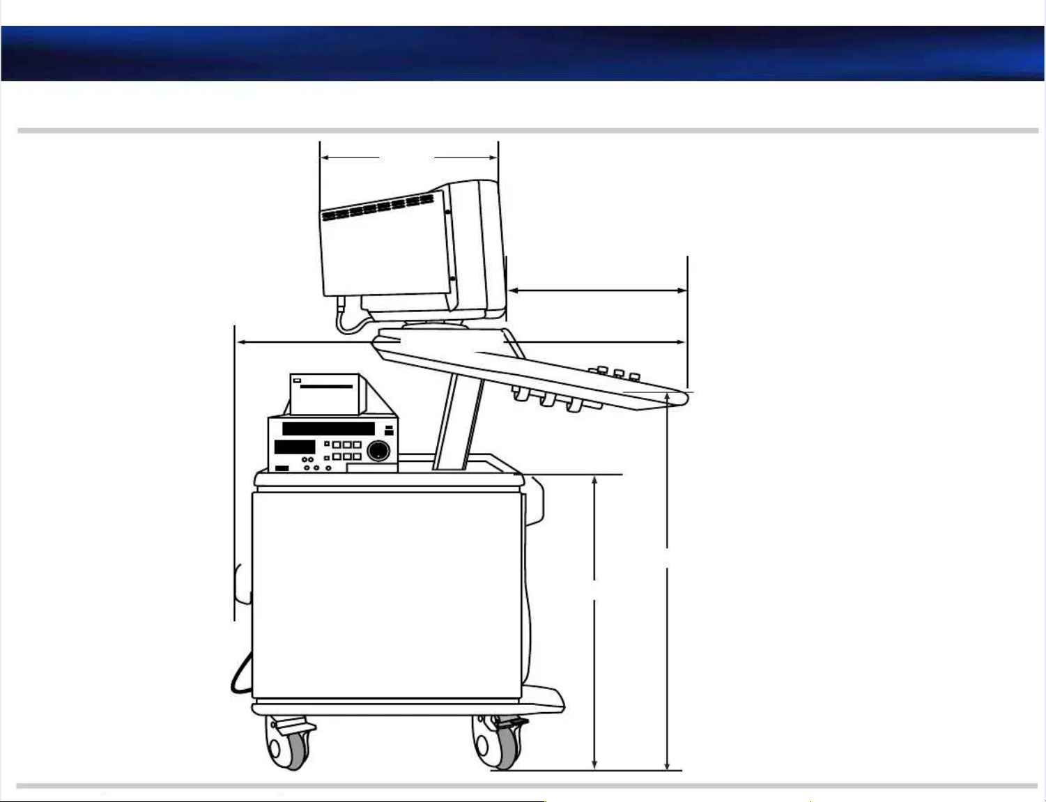
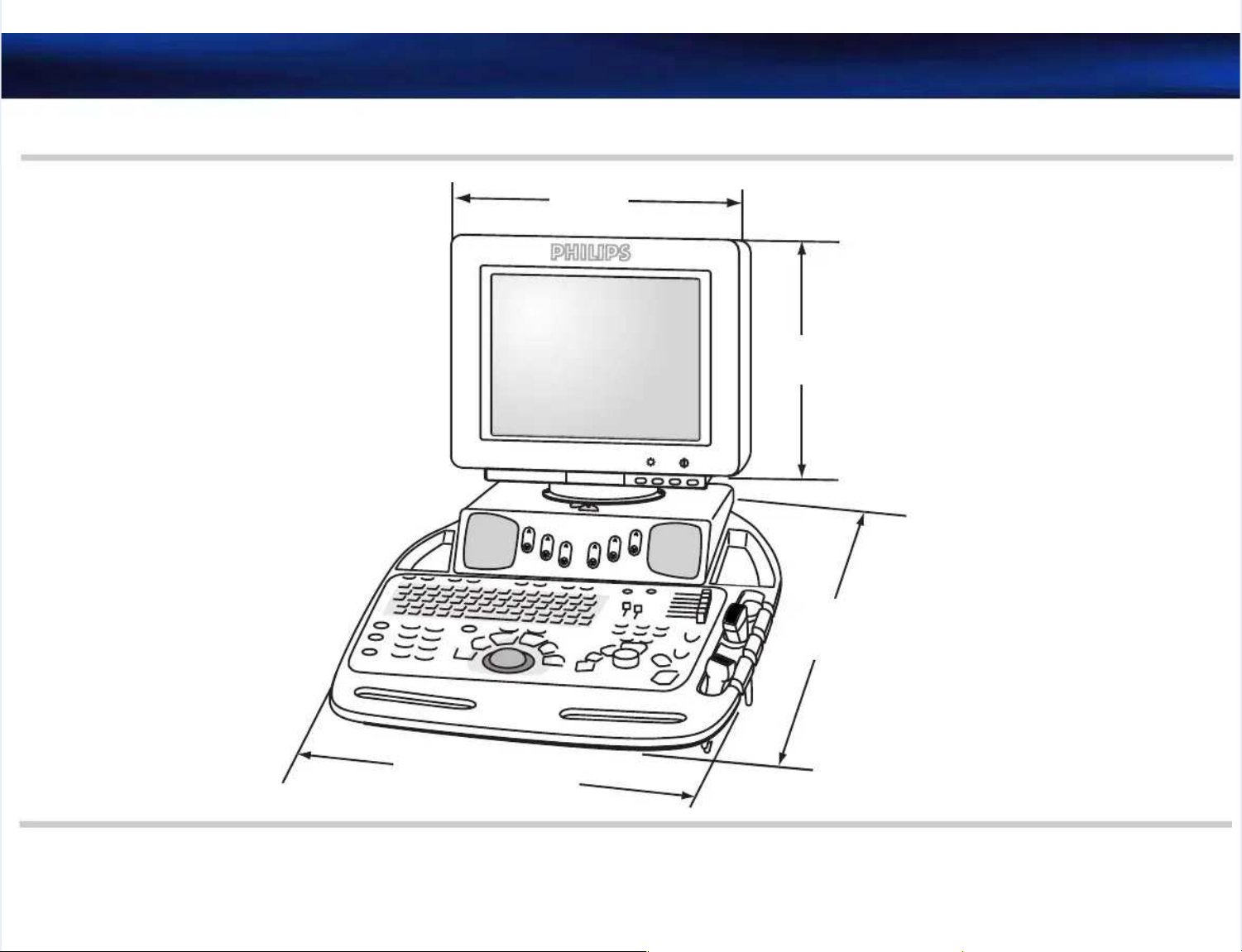
Specifications: Physical DimensionsSpecifications: Physical Dimensions
PhysicalPhysical
DimensionsDimensions
The tables and diagrams that follow detail the physical specifications of the M2540A.The tables and diagrams that follow detail the physical specifications of the M2540A.
TTaabblle e 22--11 PPhhyyssiiccaal l SSppeecciiffiiccaattiioonnss
PPaarraammeetteerr SSppeecciiffiiccaattiioonn RReeffeerreennccee
DimensionsDimensions
DDeepptth h ((ffrroonnt t tto o bbaacckk)) 110033 ccm m ((4400..55 iinncchheess)) SSeeee Fi
Figugurree 2-2-22
WWiiddtthh 5533..55 ccm m ((2211 iinncchheess)) SSeeee FiFigugurree 2-2-11
HHeeiigghht t ((tto o mmoonniittoor r ttoopp)) LLoowweesst t ppoossiittiioonn: : 112299..55 ccm m ((551 1 iinncchheess))
Highest positionHighest position:: 147147.5.5 cm (5cm (58 inc8 incheshes))
SeeSee FiFigugurree 2-2-11
HHeeiigghht t oof f lloowweer r eenncclloossuurree 7766..22 ccm m ((3300 iinncchheess)) SSeeee FiFigugurree 2-2-22
MMoonniittoor r tto o ccoonnttrrool l ppaanneel l ffrroonnt t eeddggee 4433..1188 ccm m ((1177 iinncchheess)) SSeeee FiFigugurree 2-2-22
Monitor depthMonitor depth
(front to back)(front to back)
4411..7711 ccm m ((1166..4422 iinncchheess)) SSeeee FiFigugurree 2-2-22
WWeeiigghhtt LLeesss s tthhaan n 991 k1 kg g ((22000 l0 lbbss) ) iinncclluuddiinng g ddiissppllaay y bbuut t nno o ppeerriipphheerraallss SSeeee FiFigugurree 2-2-22
EEnnvviirroonnmmeennttaall OOppeerraattiioonnaall
TTemperature range: 0emperature range: 0° to 40°° to 40° CC
Relative humidity: 20% to 80%Relative humidity: 20% to 80%
Atmospheric pressurAtmospheric pressure: 572hPa e: 572hPa to 1013 hPato 1013 hPa
(VCR a(VCR and prnd printers inters tempertemperaturature limit: e limit: 0° to 40° to 40°0° C at 80C at 80%% RH)RH)
StorageStorage
TTemperature range: –emperature range: –40° to 55°40° to 55° CC
Relative humidity: 20% to Relative humidity: 20% to 90%, non-condensing90%, non-condensing
Atmospheric pressurAtmospheric pressure: 572hPa e: 572hPa to 1013 hPato 1013 hPa
Page 15

M
M22554400--9922000000--001 1 A A MM2255440 0 UUllttrraassoouunnd d SSyysstteem m FFiieelld d SSeerrvviicce e MMaannuuaall PPaagge e 1155
Specifications: Physical DimensionsSpecifications: Physical Dimensions
FFiigguurre e 22--11 SSyysstteem m FFrroonnt t DDiimmeennssiioonnss
..
..
..
......
..
..
..
..
..
..
++
--
++
--
Range:
Range:
129.5 cm (51 in) -129.5 cm (51 in) -
147.5 cm (58 in)147.5 cm (58 in)
53.5 cm53.5 cm
(21 in)(21 in)
Page 16
M
M22554400--9922000000--001 1 A A MM2255440 0 UUllttrraassoouunnd d SSyysstteem m FFiieelld d SSeerrvviicce e MMaannuuaall PPaagge e 1166
Specifications: Physical DimensionsSpecifications: Physical Dimensions
FFiigguurre e 22--22 SSyysstteem m SSiidde e DDiimmeennssiioonnss
41.71 cm41.71 cm
(16.42 in)(16.42 in)
99 cm (39 in)99 cm (39 in)
43.18 cm (17 in)43.18 cm (17 in)
74.3 cm (29.25 in)74.3 cm (29.25 in)
95.25 cm (37.5 in)95.25 cm (37.5 in)
Page 17

M
M22554400--9922000000--001 1 A A MM2255440 0 UUllttrraassoouunnd d SSyysstteem m FFiieelld d SSeerrvviicce e MMaannuuaall PPaagge e 1177
Specifications: Physical DimensionsSpecifications: Physical Dimensions
FFiigguurre e 22--33 SSyysstteem m RReeaar r DDiimmeennssiioonnss
Range:
Range:
129.5 cm (51 in) -129.5 cm (51 in) -
147.5 cm (58 in)147.5 cm (58 in)
53.5 cm (21 in)53.5 cm (21 in)
Page 18
M
M22554400--9922000000--001 1 A A MM2255440 0 UUllttrraassoouunnd d SSyysstteem m FFiieelld d SSeerrvviicce e MMaannuuaall PPaagge e 1188
Specifications: Physical DimensionsSpecifications: Physical Dimensions
FFiigguurre e 22--44 SSyysstteem m TToop p DDiimmeennssiioonnss
39.4 cm
39.4 cm
(15.5 in)(15.5 in)
33 cm33 cm
(13 in)(13 in)
72.6 cm72.6 cm
(28.5 in)(28.5 in)
55
33
..
44
55
cc
mm
((
22
11
ii
nn
))
++
--
++
--
Page 19

M
M22554400--9922000000--001 1 A A MM2255440 0 UUllttrraassoouunnd d SSyysstteem m FFiieelld d SSeerrvviicce e MMaannuuaall PPaagge e 1199
Specifications: Electrical SpecificationsSpecifications: Electrical Specifications
ElectricalElectrical
SpecificationsSpecifications
MonitorMonitor
TTaabblle e 22--22 EElleeccttrriiccaal l SSppeecciiffiiccaattiioonnss
PPaarraammeetteerr SSppeecciiffiiccaattiioonn
AAC C iinnppuutt 990 0 VVAAC C tto o 22664 4 VVAACC, , 4477 HHz z tto o 6633 HHzz
GGrroouunnd d iimmppeeddaannccee 22000 0 mmiilllilioohhm m mmaxaxiimmuumm
DiDielelecectrtric wic witithshstatandnd 15150000 VVAAC mC maiains ns to sto safafetety gy grrououndnd
20002000 V mains V mains to Ato AC secoC secondariendariess
40004000 V mainV mains to Ds to DC secC secondarondariesies
LLooaadd 1111550 0 VVA A mmaaxxiimmuumm..
AAC C oouuttppuutt 11220 0 VVAACC, , 660 0 HHzz, , qquuaassi i ssqquuaarree--wwaavvee, , 55000 0 VVA A mmaaxxiimmuumm
TTaabblle e 22--33 MMaaiin n DDiissppllaayy
PPaarraammeetteerr SSppeecciiffiiccaattiioonn
SSccrreeeen n ssiizzee 1155--iinncch h ddiiaaggoonnaall
DDiissppllaay y ffoorrmmaatt VVGGAA, , 880000xx660000
7575 Hz rHz refrefresh esh raterate
RGB color displayRGB color display
FFeeaattuurreess TTiillt t ±±330 0 ddeeggrreeeess
Swivel ±135 degreesSwivel ±135 degrees
Page 20

M
M22554400--9922000000--001 1 A A MM2255440 0 UUllttrraassoouunnd d SSyysstteem m FFiieelld d SSeerrvviicce e MMaannuuaall PPaagge e 2200
Specifications: Transducer SpecificationsSpecifications: Transducer Specifications
TransducerTransducer
SpecificationsSpecifications
The following table lists the specifications of the transducers that tThe following table lists the specifications of the transducers that the M2540A supports.he M2540A supports.
1.1. This tThis transduransducer icer is cos compatibmpatible witle with the h the M2540M2540A, but A, but is onis only soly sold sepld separatearatelyly..
TTaabblle e 22--44 TTrraannssdduucceerrss
DescriptionDescription
PartPart
NNuummbbeerr FFrreeqquueennccyy CCoonnnneeccttoor r
S4S4
11
2211333300AA CCaannnnoonn
SS8 8 2211335500AA CCaannnnoonn
SS1122 2211338800AA CCaannnnoonn
cc
3540 biopsy capable3540 biopsy capable
11
2211332211AA 33..5 5 MMHHzz CCaannnnoonn
EECC6655009 9 eennddooccaavviittyy 2211333366AA CCaannnnoonn
L7535 linearL7535 linear
2211335599AA 77..5 5 MMHHzz CCaannnnoonn
TTEEE E ((OOmmnni i IIII)) 2211336699AA 6 6 MMHHzz CCaannnnoonn
LL11003388A A ssmmaalll l ppaarrttss 2211337766AA CCaannnnoonn
1155--66L L iinnttrraaooppeerraattiivvee 2211339900AA CCaannnnoonn
PPA A 44--2 2 bbiiooppssy y ccaappaabbllee 2211442222AA 2 2 tto o 4 4 MMHHzz AAddvvaanncce e VViissiioonn
CCA A 55--22 2211442255AA 2 2 tto o 5 5 MMHHzz AAddvvaanncce e VViissiioonn
DD11991144cc 2211222211BB 11..9 9 MMHHzz PPeenncciill
Page 21

M
M22554400--9922000000--001 1 A A MM2255440 0 UUllttrraassoouunnd d SSyysstteem m FFiieelld d SSeerrvviicce e MMaannuuaall PPaagge e 2211
Specifications: Connection and Communication SpecificationsSpecifications: Connection and Communication Specifications
ConnectionConnection
and Commu-and Commu-
nicationnication
SpecificationsSpecifications
The following tables list the communication and connector specifications of the M2540A.The following tables list the communication and connector specifications of the M2540A.
System I/OSystem I/O
PortsPorts
PC PortsPC Ports
The following table lists the ports on the The following table lists the ports on the rear of the internal PC and describes their rear of the internal PC and describes their locations.locations.
TTaabblle e 22--55 PPC C PPoorrttss
PPoorrtt SSppeecciiffiiccaattiioonn
Composite video outputComposite video output
(optional)(optional)
11
Female phono (RCA) on TV and video Female phono (RCA) on TV and video convconverter boarderter board
S-Video output (optional)S-Video output (optional)
11
4-pin mini circular DIN on SVGA to TV video 4-pin mini circular DIN on SVGA to TV video cardcard
S-Video input (optional)S-Video input (optional)
11
4-pin mini circular DIN on video 4-pin mini circular DIN on video capture cardcapture card
PPrriinnt t ttrriiggggeer r oouuttppuutt 33..55--mmm m pphhoonne e jjaacck k oon n AAPPIIO O bbooaarrdd
VCR audio output (line out)VCR audio output (line out)
(optional)(optional)
11
Green 3.5-mm stereo phone jack on Green 3.5-mm stereo phone jack on sound cardsound card
VCR audio input (line in)VCR audio input (line in)
11
Blue 3.5-mm stereo phone jack Blue 3.5-mm stereo phone jack on sound cardon sound card
MMiiccrroopphhoonnee PPiinnk k 33..55--mmm m sstteerreeo o pphhoonne e jjaacckk
SSppeeaakkeerrss GGrreeeen n 33..55 mmm m sstteerreeo o pphhoonne e jjaacck k tto o ssyysstteem m ssppeeaakkeer r aammpplliiffiieerr
MMoonniittoorr 1155--ppiin n D D ccoonnnneeccttoor r oon n ggrraapphhiiccs s aaddaapptteer r bbooaarrdd
FFoooot t sswwiittcchh 99--ppiin n ffeemmaalle e DD--ssuub b ccoonnnneeccttoor r oon n tthhe e AAPPIIO O bbooaarrd d tthhaat t ccaarrrriieess
foot switch signals from the external I/O panelfoot switch signals from the external I/O panel
Page 22

M
M22554400--9922000000--001 1 A A MM2255440 0 UUllttrraassoouunnd d SSyysstteem m FFiieelld d SSeerrvviicce e MMaannuuaall PPaagge e 2222
Specifications: Connection and Communication SpecificationsSpecifications: Connection and Communication Specifications
1.1. OnlOnly avy availaailable wible with VCR oth VCR optiption or exon or exterternal vnal videideo/po/prinrint optit optionon
CCoom m 11 99--ppiin n D D ccoonnnneeccttoorr, , RRSS--223322; ; ssppaarre e sseerriiaal l ppoorrt t uusseed d ffoor r sseerriiaall
VCRsVCRs
KKeeyybbooaarrdd DDIIN N cciirrccuullaar r ccoonnnneeccttoorr
MMoouussee DDIIN N cciirrccuullaar r ccoonnnneeccttoorr
TTookkeen n rriinngg 5500--ppiin n ccoonnnneeccttoor r oon n tthhe e AAPPIIO O bbooaarrdd
LLAANN RRJJ--445 5 tto o II//O O ppaanneel l ffoor r nneettwwoorrk k ccoommmmuunniiccaattiioonn
UUSSBB UUSSB B ((AA) ) ffoor r ddaatta a aannd d ppoowweer r tto o ssyysstteem m ccoonnttrrool l ppaanneell
UUSSBB FFoor r bbllaacckk--aanndd--wwhhiitte e tthheerrmmaal l pprriinntteerr
UUSSBB FFoor r ccoolloor r pprriinntteerr
UUSSBB FFoor r rreemmootte e ppllaaiinn--ppaappeer r pprriinntteerr
PPSS--2 2 kkeeyybbooaarrdd NNoot t uusseedd
PPSS--2 2 mmoouussee NNoot t uusseedd
PPaarraalllleel l ppoorrtt NNoot t uusseedd
AAuuddiio o iinnppuut t oon n mmaaiin n bbooaarrdd NNoot t uusseedd
TTaabblle e 22--55 PPC C PPoorrtts s ((CCoonnttiinnuueedd))
PPoorrtt SSppeecciiffiiccaattiioonn
Page 23

M
M22554400--9922000000--001 1 A A MM2255440 0 UUllttrraassoouunnd d SSyysstteem m FFiieelld d SSeerrvviicce e MMaannuuaall PPaagge e 2233
Specifications: Physio Port SpecificationsSpecifications: Physio Port Specifications
I/O Panel I/O Panel PPortsorts The following table lists the ports on the I/O panel and the signals they carry.The following table lists the ports on the I/O panel and the signals they carry.
Physio PortPhysio Port
SpecificationsSpecifications
The following table lists tThe following table lists the specifications of the he specifications of the M2540A’M2540A’s physio ports.s physio ports.
Audio/VideoAudio/Video
The following tables list the audio and video specifications of the The following tables list the audio and video specifications of the M2540A.M2540A.
TTaabblle e 22--66 II//O O PPaanneel l PPoorrttss
PPoorrtt CCoonnnneeccttoorr SSiiggnnaall
CCoommppoossiitte e vviiddeeo o BBNNCC CCoommppoossiitte e vviiddeeo o ssiiggnnaal l ffrroom m SSVVGGA A bbooaarrdd
FFoooot t sswwiittcchh DD--ssuub b 99 CCoonnttrrool l ssiiggnnaal l ffrroom m ffoooot t sswwiittcch h tto o AAPPIIO O bbooaarrdd
Defaults are: record, freeze, and record 2Defaults are: record, freeze, and record 2
Each signal is a Each signal is a contact closure to ground, active lowcontact closure to ground, active low, and, and
TTL compatibleTTL compatible
PPrriinntt BBNNCC TTrriiggggeer r ssiiggnnaal l ffrroom m AAPPIIO O bbooaarrdd
LLAANN RRJJ--4455 CCoommmmuunniiccaattiioon n wwiitth h llooccaal l aarreea a nneettwwoorrk k
TTaabblle e 22--77 PPhhyyssiio o PPoorrt t SSppeecciiffiiccaattiioonnss
PPoorrtt SSppeecciiffiiccaattiioonn
EECCGG 3 3 ppaattiieennt t lleeaadds s wwiitth h RR--wwaavve e ddeetteeccttiioonn
Monitoring quality onlyMonitoring quality only
FreqFrequency ruency responesponse: 1 ±0.5 to 30 ±6se: 1 ±0.5 to 30 ±6 HzHz
Sensitivity: 3 mVpp ±2.5 mV for full scale at 100% gainSensitivity: 3 mVpp ±2.5 mV for full scale at 100% gain
Aux Aux 1 1 3-dB 3-dB bandwidth: bandwidth: full full scale scale DC DC to to 100 100 Hz Hz minimumminimum
MaximMaximum ium input nput signalsignal: ±4: ±4 VV
Sensitivity: 2.5 ±0.5 Vpp for full scale at 100% gaSensitivity: 2.5 ±0.5 Vpp for full scale at 100% gainin
Page 24

SpecificationsSpecifications
M
M22554400--9922000000--001 1 A A MM2255440 0 UUllttrraassoouunnd d SSyysstteem m FFiieelld d SSeerrvviicce e MMaannuuaall PPaagge e 2244
Specifications: Audio/Video SpecificationsSpecifications: Audio/Video Specifications
AudioAudio
External VideoExternal Video
TTaabblle e 22--88 AAuuddiio o SSppeecciiffiiccaattiioonnss
DDeessccrriippttiioonn SSppeecciiffiiccaattiioonn
SSppeeaakkeerrss SStteerreeoo——VVCCRR, , DDoopppplleerr
Doppler spectrum toward transducer — left Doppler spectrum toward transducer — left speakerspeaker
Doppler spectrum away from transducer — right speakerDoppler spectrum away from transducer — right speaker
Maximum power input: 4 wattsMaximum power input: 4 watts
Impedance: 8 ohmsImpedance: 8 ohms
FrequencyFrequency
ResponseResponse
130 Hz to 12 KHz130 Hz to 12 KHz
MMiiccrroopphhoonnee FFaaccees fs frroonntt. 1. 10 H0 Hz tz to 2o 20 K0 KHHz ez elleeccttrreet tt tyyppee
TTaabblle e 22--99 EExxtteerrnnaal l VViiddeeo o SSppeecciiffiiccaattiioonnss
DDeessccrriippttiioonn SSppeecciiffiiccaattiioonn
CoCololor Cr Comompoposisitete NTNTSC SC 3.3.58 58 (U(USASA), P), PAL AL 4.4.43 43 (E(Eururopope)e)
1.01.0 V p to p ±5% into 75 ohmV p to p ±5% into 75 ohms (only ws (only with VCR optiith VCR option)on)
PPrriinntt TTrriiggggeer r 1 1 ssiiggnnaal l ffrroom m tthhe e AAPPIIO O bbooaarrdd
ActivActive low: ON = 0.5 V max @ 1e low: ON = 0.5 V max @ 1 mA; OFF = 5.25 VmA; OFF = 5.25 VDC maximDC maximumum
voltagevoltage
Page 25

M
M22554400--9922000000--001 1 A A MM2255440 0 UUllttrraassoouunnd d SSyysstteem m FFiieelld d SSeerrvviicce e MMaannuuaall PPaagge e 2255
Specifications: Audio/Video SpecificationsSpecifications: Audio/Video Specifications
Video OutputVideo Output
SpecificationsSpecifications
TTaabblle e 22--1100 VViiddeeo o OOuuttppuut t SSppeecciiffiiccaattiioonnss
OOuuttppuutt SSppeecciiffiiccaattiioonn
RGBSync to systemRGBSync to system
monitormonitor
0.7 Vpp RGB with TTL sync0.7 Vpp RGB with TTL sync
S-Video Output toS-Video Output to
VCRVCR
1.0 Vpp luminance incorporating sync and 1.0 Vpp luminance incorporating sync and 0.3 Vpp chrominance as0.3 Vpp chrominance as
shown inshown in TTabablele 2-2-99. This timing is essentially RS-170 (60 Hz) or CCIR. This timing is essentially RS-170 (60 Hz) or CCIR
(50Hz) video timing.(50Hz) video timing.
Page 26

M
M22554400--9922000000--001 1 A A MM2255440 0 UUllttrraassoouunnd d SSyysstteem m FFiieelld d SSeerrvviicce e MMaannuuaall PPaagge e 2266
Safety:Safety:
3 3 SSaaffeettyy
This section provides an overview of safety considerations for the ultrasound system. This section provides an overview of safety considerations for the ultrasound system. TheseThese
safety concerns apply to patients, operators, and service engineers. For more detailed safetysafety concerns apply to patients, operators, and service engineers. For more detailed safety
information, see theinformation, see the Philips Safety and Standards GuidePhilips Safety and Standards Guide..
The following topics are included in this The following topics are included in this section:section:
••
“T
“Transmit Pransmit Power ower (Acoustical)” on page(Acoustical)” on page 2727
•• “Acou“Acoustic Exstic Exposurposure” on pae” on pagege 2727
•• “AIUM/“AIUM/NEMA OutpuNEMA Output Displat Display Standary Standard” on paged” on page 2828
•• “Explo“Explosivsive Hazare Hazards” on ds” on pagepage 3030
••
“Elect
“Electrical Wrical Warninarnings” on paggs” on pagee 3131
•• “Per“Peripheraipheral Connel Connectionsctions” on page” on page 3131
••
“Gluta
“Glutaraldehraldehyde Expoyde Exposursure” on pagee” on page 3232
•• “Movi“Moving the ng the SystemSystem” on ” on pagepage 3232
••
“Electr
“Electromagnetomagnetic Compatiic Compatibilitybility” on page” on page 3535
•• “Restr“Restrictionictions fos for Use” or Use” on pagen page 3636
••
“Electr
“Electrosurgosurgical Uniical Units” on pats” on pagege 3737
Page 27

M
M22554400--9922000000--001 1 A A MM2255440 0 UUllttrraassoouunnd d SSyysstteem m FFiieelld d SSeerrvviicce e MMaannuuaall PPaagge e 2277
Safety: Transmit Power (Acoustical)Safety: Transmit Power (Acoustical)
TransmitTransmit
PowerPower
(Acoustical)(Acoustical)
Acoustic output, expressed as an index, Acoustic output, expressed as an index, is displayis displayed on the screen to ed on the screen to allow the best possibleallow the best possible
diagnostic image with diagnostic image with minimal power output. A display standard presents this index using one ofminimal power output. A display standard presents this index using one of
the following four power indices:the following four power indices:
•• Mechanical index (MI)Mechanical index (MI)
•• Thermal index for soft tissue (TIS)Thermal index for soft tissue (TIS)
•• Thermal index for bone (TIB)Thermal index for bone (TIB)
••
Thermal index for cranial bone (TIC)Thermal index for cranial bone (TIC)
The index setting on theThe index setting on theSystem SetupSystem Setupmenu selects the menu selects the power index used. The displayedpower index used. The displayed
index is based on this setting and index is based on this setting and on preset configuration and imaging mode.on preset configuration and imaging mode.
••
The power index setting on theThe power index setting on the
System SetupSystem Setup
menu selects any of the four power indicesmenu selects any of the four power indices
for display at any time.for display at any time.
•• TheThe PowerPowerrotary control at the right side of the rotary control at the right side of the system control panel is the only contrsystem control panel is the only controlol
that affects transmit that affects transmit power levpower level.el.
For additional information on acoustical power settings and For additional information on acoustical power settings and power index, see thepower index, see the Philips SafetyPhilips Safety
and Standards Guideand Standards Guide..
AcousticAcoustic
ExposureExposure
Although no harmful effects have been demonstrated for any of the Although no harmful effects have been demonstrated for any of the ultrasound frequencies,ultrasound frequencies,
intensities, and exposure times used in examinations with Philips ultrasound systems, Philipsintensities, and exposure times used in examinations with Philips ultrasound systems, Philips
recommends that you consider the following, and use trecommends that you consider the following, and use the lowest ultrasound exposure thathe lowest ultrasound exposure that
produces diagnostically acceptable information:produces diagnostically acceptable information:
••
Use diagnostic ultrasound only when tUse diagnostic ultrasound only when there is a good medical here is a good medical reason.reason.
•• Reset the controls at the start Reset the controls at the start of every examination.of every examination.
Page 28

M
M22554400--9922000000--001 1 A A MM2255440 0 UUllttrraassoouunnd d SSyysstteem m FFiieelld d SSeerrvviicce e MMaannuuaall PPaagge e 2288
Safety: AIUM/NEMA Output Display StandardSafety: AIUM/NEMA Output Display Standard
•• Reduce exposure time, independent of acoustic index value.Reduce exposure time, independent of acoustic index value.
•• Use techniques that leUse techniques that let you collect clinical data t you collect clinical data quickly and end the equickly and end the examination promptlyxamination promptly..
•• Select a transducer that Select a transducer that provprovides good resolution and focal depth ides good resolution and focal depth for the region of interest.for the region of interest.
Then use the imaging controls to fine-tune image Then use the imaging controls to fine-tune image resolution.resolution.
For more detailed information on acoustic exposure, see theFor more detailed information on acoustic exposure, see the Output Display Standards and ODSOutput Display Standards and ODS
Acoustic TAcoustic Tablesablesbooklet.booklet.
AIUM/NEMAAIUM/NEMA
OutputOutput
DisplayDisplay
StandardStandard
In compliance with the In compliance with the Output Display Standard (ODS) jointly proposed by the AmericanOutput Display Standard (ODS) jointly proposed by the American
Institute of Ultrasound in Medicine and the Institute of Ultrasound in Medicine and the National Electrical Manufacturers Association, theNational Electrical Manufacturers Association, the
Philips ultrasound system displays power output indices related to the potential Philips ultrasound system displays power output indices related to the potential for bioeffects.for bioeffects.
Real-time information related to Real-time information related to the power output is displayed on the monitorthe power output is displayed on the monitor, indicating the, indicating the
type of index displayed and the value of type of index displayed and the value of that index that index for the acoustic output currently being used.for the acoustic output currently being used.
For example, if For example, if the output corresponds to a mechanical index the output corresponds to a mechanical index of 0.8, the of 0.8, the following is displayfollowing is displayed:ed:
MI: 0.8MI: 0.8
The displayThe displayed index is one ed index is one of four types: MI, TIS, of four types: MI, TIS, TIB, or TIC. TIB, or TIC. These ultrasound abbreviationsThese ultrasound abbreviations
conform to the AIUM/NEMA Output conform to the AIUM/NEMA Output DisplaDisplay Standard.y Standard.
Soft tissue thermal index (TIS) is Soft tissue thermal index (TIS) is used in cardiac, fetal, and abdominal scanning.used in cardiac, fetal, and abdominal scanning.
The thermal index for bone (TIB) is used in applications such as second or third trimester fetalThe thermal index for bone (TIB) is used in applications such as second or third trimester fetal
scanning and neonatal cephalic (through the fontanelle) scanning.scanning and neonatal cephalic (through the fontanelle) scanning.
The cranial bone thermal index (TIC) is used for transcranial imaging.The cranial bone thermal index (TIC) is used for transcranial imaging.
Page 29

M
M22554400--9922000000--001 1 A A MM2255440 0 UUllttrraassoouunnd d SSyysstteem m FFiieelld d SSeerrvviicce e MMaannuuaall PPaagge e 2299
Safety: AIUM/NEMA Output Display StandardSafety: AIUM/NEMA Output Display Standard
NOTENOTE The power index displayThe power index displayed on the ed on the screen depends on the preset type, screen depends on the preset type, the activethe active
transducer type, the imaging transducer type, the imaging mode, and the selectemode, and the selected power index. Any of the fourd power index. Any of the four
power indices is selectable for displapower indices is selectable for display at any time, using the y at any time, using the power index setting in thepower index setting in the
System SetupSystem Setupmenu.menu.
AutomaticAutomatic
Index SelectionIndex Selection
For automatic selection of a power index based on system mode, the user selects the powerFor automatic selection of a power index based on system mode, the user selects the power
index setting ofindex setting of
NormalNormal
from thefrom the
System SetupSystem Setup
menu. This directs the system to choose anmenu. This directs the system to choose an
index based on the active preset and imaging modeindex based on the active preset and imaging mode..
When MI iWhen MI is Displas Displayeyed With the d With the Normal SeNormal Settingtting
MI is displayed if any of the following conditions exist:MI is displayed if any of the following conditions exist:
•• 2D Only is the active imaging mode.2D Only is the active imaging mode.
•• Black-and White MMode Preview is the active imaging mode.Black-and White MMode Preview is the active imaging mode.
•• Black-and White Doppler Preview is the active imaging mode.Black-and White Doppler Preview is the active imaging mode.
••
Black-and White Doppler 2D Live is the active imaging modeBlack-and White Doppler 2D Live is the active imaging mode..
When TIS iWhen TIS is Displas Displayeyed With Normd With Normal Settingal Setting
If none of the conditions inIf none of the conditions in “When MI is
“When MI is DisplaDisplayed With yed With the Normal Setting” othe Normal Setting” on pagen page 2929exist, ifexist, if
no transcranial preset is active, no transcranial preset is active, and any of the following conditions exist, and any of the following conditions exist, TIS displays:TIS displays:
•• Color is turned on.Color is turned on.
•• Angio is turned on.Angio is turned on.
••
MMode TMMode Trace is race is the active ithe active imaging mode.maging mode.
••
Doppler Spectral is the active imaging mode (wiDoppler Spectral is the active imaging mode (with 2D Live off).th 2D Live off).
Page 30

M
M22554400--9922000000--001 1 A A MM2255440 0 UUllttrraassoouunnd d SSyysstteem m FFiieelld d SSeerrvviicce e MMaannuuaall PPaagge e 3300
Safety: Explosive HazardsSafety: Explosive Hazards
When TIC is When TIC is DisplaDisplayeyed With Normd With Normal Settingal Setting
If none of the conditions inIf none of the conditions in “When MI is Disp
“When MI is Displalayed Wityed With the Normal Settinh the Normal Setting” on pageg” on page 2929exist, aexist, a
transcranial preset is active, and transcranial preset is active, and any of the following conditions exist, any of the following conditions exist, TIS displays:TIS displays:
•• Color is turned on.Color is turned on.
•• Angio is turned on.Angio is turned on.
•• MMode TMMode Trace is race is the active ithe active imaging mode.maging mode.
••
Doppler Spectral is the active imaging mode (wiDoppler Spectral is the active imaging mode (with 2D Live off).th 2D Live off).
If the user selects an ODS setting other than Normal, the selected index type is used as theIf the user selects an ODS setting other than Normal, the selected index type is used as the
preferrpreferred acoustic power display format, regardless of the ed acoustic power display format, regardless of the mode, the mode, the transducertransducer, or , or the presetthe preset
that is selected.that is selected.
The displayThe displayed index value ed index value does not provide an exact value does not provide an exact value of the potential of the potential for adverse bioeffectsfor adverse bioeffects
in the patiein the patient. Howevnt. Howeverer, for any patient, the , for any patient, the higher the valuehigher the value, the higher , the higher the potential for athe potential for adversedverse
bioeffects. The user can minimize the bioeffects. The user can minimize the potential for bioeffects by keeping the index value as low aspotential for bioeffects by keeping the index value as low as
possible, by choosing the right transducer and making adjustments. Minimizing examination timepossible, by choosing the right transducer and making adjustments. Minimizing examination time
also minimizes bioeffects.also minimizes bioeffects.
W
WARNINGARNING The ODS power index formulas were defined for reasonable worst case patient The ODS power index formulas were defined for reasonable worst case patient conditions. It isconditions. It is
likely that a particular patient's actual likely that a particular patient's actual conditions are better than indicated by the index. Theconditions are better than indicated by the index. The
operator should be aware of patient conditions that mitigate the actual operator should be aware of patient conditions that mitigate the actual exposure.exposure.
ExplosiveExplosive
HazardsHazards
Observe the Observe the following practices to following practices to avavoid explosive hazards:oid explosive hazards:
•• Do not operate the system in the presence of flammable anesthetics.Do not operate the system in the presence of flammable anesthetics.
Page 31

M
M22554400--9922000000--001 1 A A MM2255440 0 UUllttrraassoouunnd d SSyysstteem m FFiieelld d SSeerrvviicce e MMaannuuaall PPaagge e 3311
Safety: Electrical WarningsSafety: Electrical Warnings
•• When using the imaging system in When using the imaging system in the operating room, do not switch system power on orthe operating room, do not switch system power on or
off. Be sure system power is on before the operation off. Be sure system power is on before the operation starts, and starts, and leavleave it on e it on for the durationfor the duration
of the procedure.of the procedure.
W
WARNINGARNING Do not use the foot switch in the operating room.Do not use the foot switch in the operating room.
ElectricalElectrical
WWarningsarnings
Observe the following precautions to prevent electric shock:Observe the following precautions to prevent electric shock:
•• Only qualified serOnly qualified service personnel should remove system covvice personnel should remove system covers (trim and serers (trim and service panels).vice panels).
Accidental contact with Accidental contact with electrical circuits inside the system electrical circuits inside the system could cause serious injury.could cause serious injury.
•• Use only the power cords supplied with the Use only the power cords supplied with the system, and connect them system, and connect them only to properlyonly to properly
grounded electrical outlets.grounded electrical outlets.
W
WARNINGSARNINGS
•• Failure to follow these warnings can Failure to follow these warnings can affect both patient affect both patient and operator safetyand operator safety..
•• Do not connect the ultrasound system to the same circuit used for life support devices.Do not connect the ultrasound system to the same circuit used for life support devices.
PeripheralPeripheral
ConnectionsConnections
Peripherals (such as a VCR or a printer) typically meet general elePeripherals (such as a VCR or a printer) typically meet general electrical safety usagectrical safety usage
requirements, but do not meet medical requirements, but do not meet medical device standards. Therefordevice standards. Therefore, do e, do not use systemnot use system
peripherals within six feet peripherals within six feet of a patient of a patient unless the peripherals receive power from an isolatedunless the peripherals receive power from an isolated
power outlet on the imaging system, or power outlet on the imaging system, or from an isolation transformer that meets medical from an isolation transformer that meets medical safetysafety
standards. The 120 VAstandards. The 120 VAC outlets C outlets on the power supply are ion the power supply are isolated. The solated. The specific peripherals listedspecific peripherals listed
inin “Optio
“Optional Pnal Peripheeripherals” orals” on pagen page 201201meet medical device standards when installed in themeet medical device standards when installed in the
system as recommended.system as recommended.
Page 32

M
M22554400--9922000000--001 1 A A MM2255440 0 UUllttrraassoouunnd d SSyysstteem m FFiieelld d SSeerrvviicce e MMaannuuaall PPaagge e 3322
Safety: Glutaraldehyde ExposureSafety: Glutaraldehyde Exposure
Glutaral-Glutaral-
dehydedehyde
ExposureExposure
The United States Occupational Safety and HealtThe United States Occupational Safety and Health Administration (OSHA) has issued ah Administration (OSHA) has issued a
regulation dealing with regulation dealing with levels of acceptable glutaraldehyde exposure in the levels of acceptable glutaraldehyde exposure in the working environworking environment.ment.
Philips does not Philips does not sell glutaraldehyde-based disinfectants with sell glutaraldehyde-based disinfectants with its products. Howevits products. Howeverer, this , this type oftype of
disinfectant is recommended for disinfection of transesophageal (TEE) disinfectant is recommended for disinfection of transesophageal (TEE) or endocavityor endocavity
transducers.transducers.
TTo minimize o minimize exposure to glutaraldehyde fumes, make sure the exposure to glutaraldehyde fumes, make sure the area is well ventilated area is well ventilated and useand use
approprappropriate eye and iate eye and skin protection.skin protection.
Moving theMoving the
SystemSystem
Although the system is designed to be mobile, remember that it isAlthough the system is designed to be mobile, remember that it is
very heavyvery heavy
, and that you, and that you
must take precautions when moving the system.must take precautions when moving the system.
The ultrasound system has been The ultrasound system has been designed to be as designed to be as lightweight and mobile lightweight and mobile as possible. Howeveras possible. However,,
the system weight—including the system weight—including the weight of the weight of the monitorthe monitor, a , a printerprinter, and , and a +VCR—isa +VCR—is
approapproximately 100 kg (ximately 100 kg (220 pounds). Because of this 220 pounds). Because of this weight, you must use caution when movingweight, you must use caution when moving
the system, since the abilithe system, since the ability to move any ultrasound machine is directly related to an individual’ty to move any ultrasound machine is directly related to an individual’ss
size and strength.size and strength.
Some sonographers, particularly those weighing less Some sonographers, particularly those weighing less than 100 pounds, have stated that theythan 100 pounds, have stated that they
injured their backs moving similar systems. These complaints could not be directly tied to oneinjured their backs moving similar systems. These complaints could not be directly tied to one
particular incident. particular incident. They do, howThey do, howeverever, point out , point out the need to the need to be careful in transporting be careful in transporting medicalmedical
equipment such as an ultrasound system.equipment such as an ultrasound system.
Before MovingBefore Moving
the Systemthe System
TTo move the system, o move the system, take the precautions listed take the precautions listed in the in the following sections, andfollowing sections, and
••
Before moving the system, be sure to Before moving the system, be sure to removremove any loose equipment from the te any loose equipment from the top of the sys-op of the sys-
tem, disconnect the tem, disconnect the system power cord, and disconnect all external devices.system power cord, and disconnect all external devices.
•• Before transporting the system in a Before transporting the system in a vehicle, remove the monitor and all transducers from thevehicle, remove the monitor and all transducers from the
system and put them in a packing box.system and put them in a packing box.
Page 33

M
M22554400--9922000000--001 1 A A MM2255440 0 UUllttrraassoouunnd d SSyysstteem m FFiieelld d SSeerrvviicce e MMaannuuaall PPaagge e 3333
Safety: Moving the SystemSafety: Moving the System
When MoWhen Movingving
the Systemthe System
This system is equipped with a front handle and brakes on the front wheels.This system is equipped with a front handle and brakes on the front wheels.
Always use the handle at the front of the cart to move the system from place to place.Always use the handle at the front of the cart to move the system from place to place.
W
WARNINGARNING Never strap or secure the system at any point above the peripheral tray.Never strap or secure the system at any point above the peripheral tray.
NOTENOTE Use caution and follow these steps when moving the system from patient to patient.Use caution and follow these steps when moving the system from patient to patient.
1.1. UnlUnlock ock the wthe wheeheel locl locks bks befoefore re movmoving ting the syhe systestem.m.
2.2. MakMake sure sure the coe the contrntrol top ol top is lockis locked, to pred, to prevevent its ent its pivopivoting duting during trring transpoansport.rt.
3.3. Engage Engage the trthe track loack locks ocks on the n the frofront whnt wheels to eels to ease sease straighttraight-line t-line travravel.el.
4.4. PusPush wih with tth the hhe handandle ale at tht the fre front ont of tof the che cart.art.
5.5. After thAfter the syste system is in em is in positposition, enion, engage the gage the wheel lowheel locks to cks to immobiimmobilize thlize the syse system, and tem, and unlocunlockk
the control top to allow it to pivot.the control top to allow it to pivot.
Moving onMoving on
Ramps orRamps or
Uneven SurfacesUneven Surfaces
Do not move the system over unevDo not move the system over uneven elevator entrances by lifting the machine or en elevator entrances by lifting the machine or any part of theany part of the
machine.machine.
AlwayAlways use two people when s use two people when moving the ultrasound system up amoving the ultrasound system up and down ramps longer than nd down ramps longer than 2020
feet or steeper feet or steeper than 5 degrees. (Wheelchair ramps are than 5 degrees. (Wheelchair ramps are usually less than 5 usually less than 5 degrees.) Avoid rampsdegrees.) Avoid ramps
that are steeper than that are steeper than 10 degrees, to eliminate 10 degrees, to eliminate the danger of the danger of the system tipping the system tipping overover..
System TiltingSystem Tilting The system has been tested for stability using the IEC 60601-1 test protocol. Following thisThe system has been tested for stability using the IEC 60601-1 test protocol. Following this
protocol, the system will not protocol, the system will not tip over on an incline tip over on an incline of up to of up to 10 degrees in any direction. When10 degrees in any direction. When
this amount of this amount of incline is exceeded, incline is exceeded, there is a potential there is a potential for the system to for the system to tip overtip over..
Page 34

M
M22554400--9922000000--001 1 A A MM2255440 0 UUllttrraassoouunnd d SSyysstteem m FFiieelld d SSeerrvviicce e MMaannuuaall PPaagge e 3344
Safety: Moving the SystemSafety: Moving the System
WWARNINGARNING
Use care when tilting the system for an inclineUse care when tilting the system for an incline. The amount of incline allowable to prevent. The amount of incline allowable to prevent
tip-over is 10 degrees. Moving the system over a roadside curb or other tip-over is 10 degrees. Moving the system over a roadside curb or other small but steep inclinesmall but steep incline
can cause the system to exceed 10 degrees of incline.can cause the system to exceed 10 degrees of incline.
TransportingTransporting
the System in athe System in a
VehicleVehicle
AlwayAlways engage the wheel locks while s engage the wheel locks while transporting the system in a transporting the system in a vehicle, and use restrainingvehicle, and use restraining
straps to secure the system in place. Do not rely on the wheel locks to hold the system onstraps to secure the system in place. Do not rely on the wheel locks to hold the system on
inclininclines gres greater theater than 5an 5 degrdegrees.ees.
Be sure that the transporting vehicle can handle the Be sure that the transporting vehicle can handle the weight of the system (or systems) plus theweight of the system (or systems) plus the
passengers.passengers.
Be sure the load capacity of the loading lift Be sure the load capacity of the loading lift can accommodate the weight of the ultrasoundcan accommodate the weight of the ultrasound
system. A minimum capacity of system. A minimum capacity of 550 pounds is recommended.550 pounds is recommended.
AlwayAlways secure the ultrasound system while it is on the loading s secure the ultrasound system while it is on the loading lift so that it cannot lift so that it cannot roll. Makeroll. Make
sure the control top is locked, to prevent its pivoting. Engage the wheel sure the control top is locked, to prevent its pivoting. Engage the wheel locks and use woodlocks and use wood
chocks, restraining straps, or other similar types of constraints as an added safety measure. Dochocks, restraining straps, or other similar types of constraints as an added safety measure. Do
not attempt tnot attempt to hold the system o hold the system in place manuallyin place manually..
W
WARNINGARNING Never strap or secure the system at any point on the control top or monitor.Never strap or secure the system at any point on the control top or monitor.
Load and unload the ultrasound system while the tLoad and unload the ultrasound system while the transporting vehicle is parked on a levelransporting vehicle is parked on a level
surface. The system’s wsurface. The system’s weight can easily cause eight can easily cause it to roll on any inclineit to roll on any incline..
The system’The system’s weight on an extended ls weight on an extended loading lift may cause the transporting vehicle to toading lift may cause the transporting vehicle to tilt, whichilt, which
could cause personal injury or system damage.could cause personal injury or system damage.
Page 35

M
M22554400--9922000000--001 1 A A MM2255440 0 UUllttrraassoouunnd d SSyysstteem m FFiieelld d SSeerrvviicce e MMaannuuaall PPaagge e 3355
Safety: Electromagnetic CompatibilitySafety: Electromagnetic Compatibility
WWARNINGARNING
Never ride on a loading lNever ride on a loading lift with the ift with the system. Ysystem. Your weight combined with tour weight combined with the system's weight canhe system's weight can
exceed the exceed the lift's load capacitylift's load capacity..
Be sure the ultrasound system is firmly secured while inside the transporting vehicle. AnyBe sure the ultrasound system is firmly secured while inside the transporting vehicle. Any
movement, combined with the system’movement, combined with the system’s weight, could cause the s weight, could cause the system to break loose.system to break loose.
NOTENOTE
If you use the ultrasound system in a mobile van, follow the same fundamentalIf you use the ultrasound system in a mobile van, follow the same fundamental
transporting precautions listed in the sections above.transporting precautions listed in the sections above.
Electromag-Electromagneticnetic
CompatibilityCompatibility
This system has been tested for electromagnetic compatibility (EMC) according to theThis system has been tested for electromagnetic compatibility (EMC) according to the
international standard for EMC with medical devices, as determined by the Internationalinternational standard for EMC with medical devices, as determined by the International
Electrotechnical Commission (IEC 60601-1-2). This IEC standard has been Electrotechnical Commission (IEC 60601-1-2). This IEC standard has been adopted in Europe asadopted in Europe as
the European Norm EN 60601-1-2.the European Norm EN 60601-1-2.
AvoidingAvoiding
Electromag-Electromagneticnetic
InterferenceInterference
Medical devices can generate or Medical devices can generate or receive electrreceive electromagnetic interference (EMI). The EMC standardsomagnetic interference (EMI). The EMC standards
describe tests for both emittdescribe tests for both emitted and received interference. Emission tests deal ed and received interference. Emission tests deal with interferencewith interference
generated by the device being tested. The Philips ultrasound system does not generategenerated by the device being tested. The Philips ultrasound system does not generate
interference based on the tests described in the standards.interference based on the tests described in the standards.
Ultrasound systems are designed to receive radio frequency (RF) energy Ultrasound systems are designed to receive radio frequency (RF) energy and are thereforeand are therefore
susceptible to EMI generated susceptible to EMI generated by other RF energy sources. Examples of other sources of EMI areby other RF energy sources. Examples of other sources of EMI are
medical devices, information technology medical devices, information technology products, and radio and tproducts, and radio and television transmission towers.elevision transmission towers.
TTracing the source of racing the source of radiated interference can radiated interference can be a be a difficult task.difficult task.
SeeSee “Elect
“Electromromagnetiagnetic Interferc Interference” on pageence” on page 137137to identify to identify sources of EMI.sources of EMI.
Only a physician can determine if an artifact caused by radiated interference has a negativeOnly a physician can determine if an artifact caused by radiated interference has a negative
Page 36

impact on image quality and the subsequent diagnosis.impact on image quality and the subsequent diagnosis.
M
M22554400--9922000000--001 1 A A MM2255440 0 UUllttrraassoouunnd d SSyysstteem m FFiieelld d SSeerrvviicce e MMaannuuaall PPaagge e 3366
Safety: Restrictions for UseSafety: Restrictions for Use
RestrictionsRestrictions
for Usefor Use
The M2540A ultrasound system is subject to certain restrictions that are described in theThe M2540A ultrasound system is subject to certain restrictions that are described in the
following sections.following sections.
Immunity LevelImmunity Level
TTest est ResuResultslts
The EMC standards require that manufacturers of patient-coupled equipment specifyThe EMC standards require that manufacturers of patient-coupled equipment specify
electrostatic discharge immunity levels for their systems. This type of electrostatic discharge immunity levels for their systems. This type of device is designed todevice is designed to
receive and amplify low-levreceive and amplify low-level signals in the same bandwidth ael signals in the same bandwidth as the interference to which it iss the interference to which it is
susceptible.susceptible.
Immunity is defined in the standard as the ability of Immunity is defined in the standard as the ability of a system to perform without degradation ina system to perform without degradation in
the presence of an electromagnetic disturbance. Degradation in image qualitthe presence of an electromagnetic disturbance. Degradation in image quality is a qualitativey is a qualitative
assessment that can be subjective. The simplest way to assess degradation is to note when theassessment that can be subjective. The simplest way to assess degradation is to note when the
first sign of an arfirst sign of an artifact is seen. This method tifact is seen. This method has two advantages: It removes the issue of subjectivehas two advantages: It removes the issue of subjective
decision-making and provides the most stringent decision-making and provides the most stringent test results.test results.
Caution should therefore be taken in Caution should therefore be taken in comparing immunity levels of different ultrasound systems.comparing immunity levels of different ultrasound systems.
The criteria used for measuring degradation are not specified by the The criteria used for measuring degradation are not specified by the standard, and can vary witstandard, and can vary withh
the manufacturer.the manufacturer.
Philips has tested each class of transducer for every operating mode over a wide range ofPhilips has tested each class of transducer for every operating mode over a wide range of
frequencies. This testing showed PW Doppler to be the frequencies. This testing showed PW Doppler to be the most susceptible to most susceptible to radio-frequencyradio-frequency
interference.interference.
Please see thePlease see the Philips Safety and Standards GuidePhilips Safety and Standards Guideshipped with your system for additionalshipped with your system for additional
information about compliance with EMC information about compliance with EMC standards.standards.
ElectrostaticElectrostatic
DischargeDischarge
Electrostatic discharges can cause the ECG hearElectrostatic discharges can cause the ECG heart rate display to increase by 10 to 15% for a t rate display to increase by 10 to 15% for a fewfew
seconds after the seconds after the discharge. Howeverdischarge. However, the ECG , the ECG heart ratheart rate display returns to normal within e display returns to normal within fourfour
seconds.seconds.
Page 37

M
M22554400--9922000000--001 1 A A MM2255440 0 UUllttrraassoouunnd d SSyysstteem m FFiieelld d SSeerrvviicce e MMaannuuaall PPaagge e 3377
Safety: Electrosurgical UnitsSafety: Electrosurgical Units
Electrosur-Electrosur-
gical Unitsgical Units
Electrosurgical units (ESUs) and other devices intentionally iElectrosurgical units (ESUs) and other devices intentionally introduce radio frequencyntroduce radio frequency
electromagnetic fields or currents into patients. Because imaging electromagnetic fields or currents into patients. Because imaging ultrasound frequencies are alsoultrasound frequencies are also
in the radio in the radio frequency range, ultrasound transducer circuits are susceptible to radio frequency range, ultrasound transducer circuits are susceptible to radio frequencyfrequency
interference. While an ESU is in use, interference. While an ESU is in use, the noise generated severely interferthe noise generated severely interferes with thees with the
black-and-white image and completely obliterates the color image.black-and-white image and completely obliterates the color image.
Page 38

M
M22554400--9922000000--001 1 A A MM2255440 0 UUllttrraassoouunnd d SSyysstteem m FFiieelld d SSeerrvviicce e MMaannuuaall PPaagge e 3388
Theory of Operation: OverviewTheory of Operation: Overview
4 4 TThheeoorry y oof f OOppeerraattiioonn
OverviewOverview This section provides a technical overview of system functions. The This section provides a technical overview of system functions. The discussion focuses on thediscussion focuses on the
main functions and features of the main functions and features of the system’system’s PC, s PC, circuit boards, and power distribution. Maincircuit boards, and power distribution. Main
system functions are also shown in the functional block diagrams at the end of this section.system functions are also shown in the functional block diagrams at the end of this section.
The M2540A’The M2540A’s internal PC replaces the s internal PC replaces the back-end electronics used in earlier back-end electronics used in earlier ultrasound systemsultrasound systems
to handle to handle displadisplay processing. The y processing. The beam processor/acoustic processor (BPbeam processor/acoustic processor (BPAP) board AP) board handles thehandles the
acoustic and beam acoustic and beam processinprocessing front-end functions.g front-end functions.
This section covers the following areas of the system:This section covers the following areas of the system:
•• “In
“Interternal PCnal PC” on pag” on pagee 3939
•• “TR B“TR Boaroards” ods” on pagn pagee 4040
••
“BP
“BPAP BoAP Board” ard” on paon pagege 4242
•• “Demod“Demodulator ulator BoarBoard” on d” on pagepage 4343
•• “AP“APIO BoIO Boarard” on pd” on pageage 4343
•• “Ph“Physio Mysio Module Oodule Optionption” on pag” on pagee 4343
•• “Syste“System Mothm Motherboaerboard” rd” on pagon pagee 4444
•• “Distr“Distributioibution Board and Connn Board and Connector Moduector Modules” on pageles” on page 4444
•• “I/“I/O PanO Panel” oel” on pagn pagee 4545
•• “Syste“System Contm Control rol Panel” Panel” on pageon page 4545
••
“Po
“Power wer SupplSupply” on py” on pageage 4646
•• “Funct“Functional Bional Block Dilock Diagramsagrams” on pag” on pagee 4747
•• “T“Transducer Safety Transducer Safety Testing: Testing: Test Setup est Setup and Theory” and Theory” on pageon page 5252
Page 39

a s uce Sa etya s uce Sa ety est g:est g: est Setupest Setup a eo ya eo y o pageo page 55
M
M22554400--9922000000--001 1 A A MM2255440 0 UUllttrraassoouunnd d SSyysstteem m FFiieelld d SSeerrvviicce e MMaannuuaall PPaagge e 3399
Theory of Operation: Internal PCTheory of Operation: Internal PC
Internal PCInternal PC The M2540A uses an internal The M2540A uses an internal PC to coordinate and PC to coordinate and perform many of the functions that requiredperform many of the functions that required
dedicated circuit boards in earlier ultrasound systems. dedicated circuit boards in earlier ultrasound systems. The power button on the front of the The power button on the front of the PCPC
is the is the system power switch. Tsystem power switch. Turning on turning on the PC starhe PC starts the ts the ultrasound system.ultrasound system.
Standard PCStandard PC
ComponentsComponents
The M2540A’The M2540A’s internal s internal PC contains the PC contains the following standard components:following standard components:
•• A motherboardA motherboard
•• A hard driveA hard drive
•• A graphics card in the A graphics card in the AGAGP slotP slot
••
The Acoustic Processor I/O (APIO) boarThe Acoustic Processor I/O (APIO) board, in a PCI slot (Seed, in a PCI slot (See “AP
“APIO BoIO Boarard” on pad” on pagege 4343))
•• A 3A 3
11
//
22
-inch floppy disk drive-inch floppy disk drive
•• A CD-RW driveA CD-RW drive
PC PortsPC Ports
The PC motherboard’The PC motherboard’s ports s ports are used as follows:are used as follows:
•• A USB port communicates with the system control panel.A USB port communicates with the system control panel.
•• A USB port A USB port communicates with an optional black-communicates with an optional black-and-white thermal printerand-white thermal printer..
••
A USB port A USB port communicates with an optional color communicates with an optional color printerprinter..
•• A USB port A USB port communicates with an optional plain-paper printercommunicates with an optional plain-paper printer..
•• A USB port communicates with the optional physio module.A USB port communicates with the optional physio module.
•• A LAN port connects the PC to a network.A LAN port connects the PC to a network.
••
A 3.5A 3.5 mm phono jack mm phono jack receives receives audio signals audio signals from a from a microphonmicrophone.e.
•• A 3.5A 3.5 mm phono jack suppmm phono jack supplies the signal that drives lies the signal that drives the system’the system’s speakerss speakers..
•• An RS-232 port (Com1) controls an optional VCR.An RS-232 port (Com1) controls an optional VCR.
Page 40

p ( ) pp ( ) p
M
M22554400--9922000000--001 1 A A MM2255440 0 UUllttrraassoouunnd d SSyysstteem m FFiieelld d SSeerrvviicce e MMaannuuaall PPaagge e 4400
Theory of Operation: TR BoardsTheory of Operation: TR Boards
VCR-Option ComponVCR-Option Components in the ents in the PCPC
The VCR option includes several cards inside the The VCR option includes several cards inside the PC and an adapter PC and an adapter that connects to the that connects to the SVGASVGA
output of toutput of the PC’he PC’s graphics adapter board. s graphics adapter board. SeeSee Fi
Figugurree 4-4-11onon ppagagee 4488for a detailedfor a detailed
represrepresentation of entation of how the VCR how the VCR option’option’s components function is components function in the n the ultrasound system.ultrasound system.
The following cards are part of tThe following cards are part of the VCR option, and he VCR option, and reside in the PC’reside in the PC’s PCI slots:s PCI slots:
•• A sound card that receives audio from the VCR, and A sound card that receives audio from the VCR, and supplies sound to the VCRsupplies sound to the VCR
••
A video capture board that receives S-Video signals from the VCRA video capture board that receives S-Video signals from the VCR
•• An SVGA-to-S-Video card that converts the SVGA signal from the graphics aAn SVGA-to-S-Video card that converts the SVGA signal from the graphics adapter board (indapter board (in
the AGP slot) to S-Video for the VCRthe AGP slot) to S-Video for the VCR
•• An SVGA adapter that connects the graphics adapter An SVGA adapter that connects the graphics adapter board to the SVGA-to-TV video cardboard to the SVGA-to-TV video card
and to the monitorand to the monitor
SeeSee “VCR
“VCR Option Option Parts” Parts” on pon pageage 198198for a list of all the components of the VCR option.for a list of all the components of the VCR option.
Optional Drive-Bay ComponentsOptional Drive-Bay Components
The PC’s drive bays accept the following components:The PC’s drive bays accept the following components:
••
The Physio module that provides ECG monitoring capability. The drive bay’s power connec-The Physio module that provides ECG monitoring capability. The drive bay’s power connec-
tor powers the module, tor powers the module, but the module but the module does not use the does not use the drive baydrive bay’’s data port. s data port. The moduleThe module
communicates with the ultrasound system through a USB cable to the PC motcommunicates with the ultrasound system through a USB cable to the PC motherboard. Seeherboard. See
“Ph
“Physio Mysio Module Oodule Optionption” on pag” on pagee 4343, and, and FiFigugurree 4-4-33onon ppaaggee 5511for detailed information onfor detailed information on
the Physio module.the Physio module.
••
A magneto-optical disk (MOD) A magneto-optical disk (MOD) drive that allows archiving of images, studies, and reports ondrive that allows archiving of images, studies, and reports on
removable disks. The MOD removable disks. The MOD uses the drive uses the drive baybay’’s data s data and power ports.and power ports.
TR BoardsTR Boards
The M2540A’The M2540A’s e-box contains two s e-box contains two transmit-and-receive (TR) boards. Each has transmit-and-receive (TR) boards. Each has a connector thata connector that
Page 41

( )( )
plugs into the plugs into the motherboard and another connector that motherboard and another connector that passes through the motherboard andpasses through the motherboard and
M
M22554400--9922000000--001 1 A A MM2255440 0 UUllttrraassoouunnd d SSyysstteem m FFiieelld d SSeerrvviicce e MMaannuuaall PPaagge e 4411
Theory of Operation: TR BoardsTheory of Operation: TR Boards
plugs into the distribution board. The two boards form electronic beams of the transmit andplugs into the distribution board. The two boards form electronic beams of the transmit and
receive signals. Each TR board contains 64 transmitters and receive signals. Each TR board contains 64 transmitters and 32 preamps multiplexed into 6432 preamps multiplexed into 64
receive channels. This allows multiplexing the system’receive channels. This allows multiplexing the system’s 64 active channels into s 64 active channels into 128 element128 element
arraarrays. Each receive channel consists of time gays. Each receive channel consists of time gain compensation (TGC) amplifiers, in compensation (TGC) amplifiers, low passlow pass
filters, 10-bit A/D converters, and one eighth of a digitfilters, 10-bit A/D converters, and one eighth of a digital beam-forming circuit. Each TR boardal beam-forming circuit. Each TR board
sends on its output bus a value that isends on its output bus a value that is the sum of the data s the sum of the data from its 32 channels plus its 18-bitfrom its 32 channels plus its 18-bit
input bus. The last TR board in this chain input bus. The last TR board in this chain outputs the final summed radio-frequency (RF) data tooutputs the final summed radio-frequency (RF) data to
the demodulator board.the demodulator board.
The transmit and The transmit and receive beam-forming coefficients for acoustic lines are downloaded on thereceive beam-forming coefficients for acoustic lines are downloaded on the
coefficient bus from the BPAP board.coefficient bus from the BPAP board.
The BPThe BPAP board generates the timing to staAP board generates the timing to start and stop each firing lrt and stop each firing line, and sends the ine, and sends the transmittransmit
signal to the TR board, through the distribution board and the connector modules to thesignal to the TR board, through the distribution board and the connector modules to the
transducertransducer. Analog drivers generate t. Analog drivers generate the transmitted RF he transmitted RF data. A digitdata. A digital timing generator al timing generator delaysdelays
and times each and times each of the analog of the analog drivers. The delay generators receive the approdrivers. The delay generators receive the appropriate delay valuespriate delay values
from the BPfrom the BPAP for each channel. The AP for each channel. The system power supply contrsystem power supply controls the amplitude ols the amplitude of theof the
transmitted transmitted wavwaveform.eform.
The received signal is preamplified, TGC amplified, low-pass filtered, and digitized (in all modesThe received signal is preamplified, TGC amplified, low-pass filtered, and digitized (in all modes
except CW). except CW). The BPThe BPAP board generates AP board generates TGC control signals through the demodulator TGC control signals through the demodulator board.board.
After being digitiAfter being digitized, the signal zed, the signal on each line on each line is delayed appris delayed appropriatelyopriately. The outputs of . The outputs of all channelsall channels
are daisy-chained together to sum the outputs. are daisy-chained together to sum the outputs. The RF data output of The RF data output of one TR board is the inputone TR board is the input
to the next TR board, and the outputs to the next TR board, and the outputs of the TR boards are summed to form the received beam.of the TR boards are summed to form the received beam.
The summed output signal (RF DATA) goes to the demodulator board.The summed output signal (RF DATA) goes to the demodulator board.
The CW Doppler signal is mixed to an analog intermediate frequency (IF) signal. The CWThe CW Doppler signal is mixed to an analog intermediate frequency (IF) signal. The CW
Doppler output is a single differential signal routed to the demodulator board.Doppler output is a single differential signal routed to the demodulator board.
Page 42

M
M22554400--9922000000--001 1 A A MM2255440 0 UUllttrraassoouunnd d SSyysstteem m FFiieelld d SSeerrvviicce e MMaannuuaall PPaagge e 4422
Theory of Operation: BPAP BoardTheory of Operation: BPAP Board
BPAP BoardBPAP Board The beam The beam processorprocessor/acoustic processor (BP/acoustic processor (BPAP) board AP) board contains two processors. One contains two processors. One of themof them
controls beam-forming, line-to-line operation. The other controls beam-forming, line-to-line operation. The other handles the processing of scanhandles the processing of scan
convconversion, color ersion, color flowflow, and , and Doppler signals.Doppler signals.
The BPAP board does the following:The BPAP board does the following:
•• Provides the interface between the PC and Provides the interface between the PC and the TR boardsthe TR boards
•• Provides the interface between the PC and the demodulator boardProvides the interface between the PC and the demodulator board
••
Receives controReceives control data sets l data sets from the PC, from the PC, processprocesses them for specific register values, es them for specific register values, andand
sends them to the TR boardssends them to the TR boards
•• Houses the transesophageal echo cardiography (TEE) transducer interface circuitry (TEEHouses the transesophageal echo cardiography (TEE) transducer interface circuitry (TEE
motor control and temperature monitoring)motor control and temperature monitoring)
••
Houses the transducer ID circuitryHouses the transducer ID circuitry
••
Detects the presence of standalone transducersDetects the presence of standalone transducers
•• Houses electronic switching that allows selection of Houses electronic switching that allows selection of a single active transducer from the a single active transducer from the fourfour
that can be connectedthat can be connected
•• Controls the high-voltage output Controls the high-voltage output from the system power supplyfrom the system power supply
Omni TEEOmni TEE
CircuitryCircuitry
The Omni The Omni Probe controProbe control circuitry l circuitry on the on the BPBPAP board supplies power to AP board supplies power to the TEE tthe TEE transducer'sransducer's
motormotor. It a. It also measures the position of lso measures the position of the angle-position sensorthe angle-position sensor. The signal . The signal is digitized is digitized and sentand sent
to the APIO board for monitoring by the PC.to the APIO board for monitoring by the PC.
The beam processor circuitry monitors thermistors in tThe beam processor circuitry monitors thermistors in the transducer and insures that highhe transducer and insures that high
voltage is not applied to the transmitter unless the voltage is not applied to the transmitter unless the thermistor values are within limits.thermistor values are within limits.
Page 43

M
M22554400--9922000000--001 1 A A MM2255440 0 UUllttrraassoouunnd d SSyysstteem m FFiieelld d SSeerrvviicce e MMaannuuaall PPaagge e 4433
Theory of Operation: Demodulator BoardTheory of Operation: Demodulator Board
DemodulatorDemodulator
BoardBoard
The demodulator board performs image and Doppler demodulation for BMode, MMode, PWThe demodulator board performs image and Doppler demodulation for BMode, MMode, PW
and CW phased and non-imaging Doppler modes, and color flow mode. It sends a baseband dataand CW phased and non-imaging Doppler modes, and color flow mode. It sends a baseband data
stream to the BPAP board.stream to the BPAP board.
The demodulator board contains the The demodulator board contains the following:following:
•• Digital filters and Digital filters and mixers for demodulating 2Dmixers for demodulating 2D, color flow, and PW RF data, color flow, and PW RF data
•• The independent transducer CW Doppler The independent transducer CW Doppler electronics and steerable CW detector functionselectronics and steerable CW detector functions
••
The 120The 120 MHz system clock. The cMHz system clock. The clock signal is distributed to the lock signal is distributed to the TR and BPTR and BPAP boards.AP boards.
•• Circuitry that generates TGC signalsCircuitry that generates TGC signals
APIO BoardAPIO Board
The acoustic processor I/O (APIO) board is the token ring The acoustic processor I/O (APIO) board is the token ring interface between the system’s PCinterface between the system’s PC
and the e-box. The APIO and the e-box. The APIO board also handles input from the foot board also handles input from the foot switch’switch’s three control buttonss three control buttons
(via the I/O panel) and forwards them to the PC(via the I/O panel) and forwards them to the PC. The board also generates trigger signals for. The board also generates trigger signals for
legacy printers.legacy printers.
The board handles these signals The board handles these signals from the PC:from the PC:
•• The R-wave pulse from the physio module that The R-wave pulse from the physio module that it sends tit sends to the o the BPBPAP boardAP board
••
The DC on-off bit that it The DC on-off bit that it sends to the power supplysends to the power supply
•• Commands that program the BPAP board at startupCommands that program the BPAP board at startup
•• Acoustic data from the Acoustic data from the BPBPAP board for the AP board for the acoustic imaging displayacoustic imaging display
Physio ModulePhysio Module
OptionOption
The self-contained Physio module The self-contained Physio module resides in one of resides in one of the PC’the PC’s drive bays. The module s drive bays. The module receivesreceives
power from the drive bay’s power connector, but it communicates with the system through apower from the drive bay’s power connector, but it communicates with the system through a
USB cable to USB cable to the PC’the PC’s motherboard. A s motherboard. A shielded and shielded and grounded enclosure pregrounded enclosure preventsvents
electromagnetic interference. Seeelectromagnetic interference. See Fi
Figugurree 4-4-33onon ppaaggee 5511for a detailed representation of thefor a detailed representation of the
Page 44

modulemodule s functions s functions and connections.and connections.
M
M22554400--9922000000--001 1 A A MM2255440 0 UUllttrraassoouunnd d SSyysstteem m FFiieelld d SSeerrvviicce e MMaannuuaall PPaagge e 4444
Theory of Operation: System MotherboardTheory of Operation: System Motherboard
PrimaryPrimary
FunctionsFunctions
The module’The module’s primary s primary functions are as follows:functions are as follows:
•• Process electroProcess electrocardiogram (ECG) signals from patient electrodes and deliver the datcardiogram (ECG) signals from patient electrodes and deliver the data to thea to the
M2540A’s PCM2540A’s PC
•• Send a detected R-wave trigger to the APIO board for frame triggering in various scanningSend a detected R-wave trigger to the APIO board for frame triggering in various scanning
modesmodes
•• Provide gain control for ECG waveformsProvide gain control for ECG waveforms
ConnectorsConnectors The Physio module has two connectors on its front panel:The Physio module has two connectors on its front panel:
•• The ECG-input connector is a The ECG-input connector is a round, 12-pin connector that is isolated round, 12-pin connector that is isolated from chassis grfrom chassis ground.ound.
•• A ¼-inch phone plug jack accepts auxiliarA ¼-inch phone plug jack accepts auxiliary input and has both signal and shield grounds.y input and has both signal and shield grounds.
SystemSystem
MotherboardMotherboard
This board connects all data This board connects all data paths between the TR boards, the paths between the TR boards, the BPBPAP board, and the AP board, and the distributiondistribution
board. It is also tboard. It is also the distribution point for DC he distribution point for DC power and ground to all boards (the BPpower and ground to all boards (the BPAP boardAP board
and distribution board and distribution board also receive power directly fralso receive power directly from the om the system power supplysystem power supply.). It .). It also sendsalso sends
filtered high voltage to the filtered high voltage to the TR boards.TR boards.
DistributionDistribution
Board andBoard and
ConnectorConnector
ModulesModules
The distribution board passes transducer signal inputs to the imaging The distribution board passes transducer signal inputs to the imaging system. The system powersystem. The system power
supply prosupply provides high voltage directly to the vides high voltage directly to the distribution board to fire transducers.distribution board to fire transducers.
Signals that pass Signals that pass through this board includethrough this board include
•• Transducer identification signals from the BPAP board to and from the transducerTransducer identification signals from the BPAP board to and from the transducer
•• TTransmit and receive signals ransmit and receive signals from the TR boards to from the TR boards to the active transducerthe active transducer
••
TEE motorTEE motor-control and temperature-sense signals -control and temperature-sense signals from the BPfrom the BPAP to AP to and from the TEE and from the TEE trans-trans-
ducerducer
Page 45

M
M22554400--9922000000--001 1 A A MM2255440 0 UUllttrraassoouunnd d SSyysstteem m FFiieelld d SSeerrvviicce e MMaannuuaall PPaagge e 4455
Theory of Operation: I/O PanelTheory of Operation: I/O Panel
TransducerTransducer
ConnectorConnector
Module TypesModule Types
The four transducer module bays accept the following types of The four transducer module bays accept the following types of modules in any combination:modules in any combination:
•• Cannon connectorCannon connector
•• Advance Vision connectorAdvance Vision connector
•• Pencil-type transducer connectorPencil-type transducer connector
•• Blank moduleBlank module
SeeSee T
Tablablee 13-13-22onon papagege 117979for a list of the modules and for a list of the modules and their part numbers.their part numbers.
I/O PanelI/O Panel The I/O panel bears The I/O panel bears four connectors and two ground points. The main system four connectors and two ground points. The main system ground used forground used for
safety testing, and an equipotential post are the tsafety testing, and an equipotential post are the two grounwo ground points on the panel.d points on the panel.
The I/O panel’s connectors areThe I/O panel’s connectors are
•• An RJ-45 (CAn RJ-45 (CAAT 5) connector for connection to T 5) connector for connection to a LANa LAN
•• A BNC connector that carries composite video signals for a legacy printerA BNC connector that carries composite video signals for a legacy printer
•• A BNC connector that carries trigger signals for a legacy printerA BNC connector that carries trigger signals for a legacy printer
••
A 9-pin D connector for the optional foot switchA 9-pin D connector for the optional foot switch
SystemSystem
Control PanelControl Panel
The system control panel contains The system control panel contains the circuitry to the circuitry to process contrprocess control inputs, the ol inputs, the system keyboarsystem keyboard,d,
rotary and slide controls, and the rotary and slide controls, and the trackball. A USB trackball. A USB cable carries control inputs from the controlcable carries control inputs from the control
panel to the panel to the PC. An PC. An auxiliary cable auxiliary cable carries power frcarries power from the system om the system power supplypower supply. The system. The system
control panel circuit board also carries control panel circuit board also carries the amplifiers the amplifiers for the system’for the system’s stereo speakers.s stereo speakers.
All control inputs and LEDs are controlled by the system’All control inputs and LEDs are controlled by the system’s PC, s PC, and their functions areand their functions are
determined by resident control-panel and system software.determined by resident control-panel and system software.
Circuit boards inside the system contrCircuit boards inside the system control panel are not field serol panel are not field serviceable or replaceable. Theviceable or replaceable. The
entire assemblyentire assembly, including circuit boards, bezel , including circuit boards, bezel assemblyassembly, and , and labels, is labels, is available as a available as a replaceablereplaceable
Page 46

M
M22554400--9922000000--001 1 A A MM2255440 0 UUllttrraassoouunnd d SSyysstteem m FFiieelld d SSeerrvviicce e MMaannuuaall PPaagge e 4466
Theory of Operation: Power SupplyTheory of Operation: Power Supply
part. Rotarpart. Rotary and sliding knobs, rotary encoders for the knobs, the trackball y and sliding knobs, rotary encoders for the knobs, the trackball assemblyassembly, and the, and the
trackball cable are all available as separate parts.trackball cable are all available as separate parts.
PPowower er SupSupplyply The M2540A power suppThe M2540A power supply is a self-contained unit that accepts AC input frly is a self-contained unit that accepts AC input from 90 to 264om 90 to 264 VV, at 50, at 50
or 60or 60 Hz, and supplies 120Hz, and supplies 120 VVAC AC at 60 Hz to the sysat 60 Hz to the system’tem’s PC, monitors PC, monitor, and two p, and two peripherals. Iteripherals. It
also provides all DC power required by system components. No switch settings also provides all DC power required by system components. No switch settings are required toare required to
configure the power supply for different AC mains; the configure the power supply for different AC mains; the power supply automatically adjusts to usepower supply automatically adjusts to use
the power connected to it. Except the power connected to it. Except for the 120 Vfor the 120 VAC to the PC, AC to the PC, all power output is activated by aall power output is activated by a
signal from the PC. signal from the PC. The system cooling fan iThe system cooling fan is the only serviceable s the only serviceable part on part on the power supplythe power supply. See. See
Fi
Figugurree 4-4-11onon ppaaggee 4488for details for details of the power supply’of the power supply’s outputs. The s outputs. The power supply activates whenpower supply activates when
it receives an “Ait receives an “AWWAKE_N” signal, which AKE_N” signal, which is generated by is generated by the PC, the PC, and then sent and then sent through the BPthrough the BPAPAP
board to the power supply.board to the power supply.
The system power supply does tThe system power supply does the following:he following:
•• Provides DC power to all Provides DC power to all system electronics through the system system electronics through the system motherboard and the motherboard and the BPBPAPAP
boardboard
•• Provides DC powProvides DC power directly to the system er directly to the system cooling fancooling fan
••
Provides high voltage to the distribution board for multiplexing Provides high voltage to the distribution board for multiplexing transducerstransducers
•• Isolates AC mains from secondary AC and DC circuitryIsolates AC mains from secondary AC and DC circuitry
••
TTransforms primary ransforms primary voltages to voltages to secondary secondary voltagesvoltages
•• Filters line ACFilters line AC
•• Provides an isProvides an isolated 120olated 120 VVAC unsAC unswitched outlet to power the internal PCwitched outlet to power the internal PC
•• Provides thrProvides three isolated 120ee isolated 120 VVAC switched outlets to powAC switched outlets to power the monitor and two peripheralser the monitor and two peripherals
Page 47

M
M22554400--9922000000--001 1 A A MM2255440 0 UUllttrraassoouunnd d SSyysstteem m FFiieelld d SSeerrvviicce e MMaannuuaall PPaagge e 4477
Theory of Operation: Functional Block DiagramsTheory of Operation: Functional Block Diagrams
FunctionalFunctional
BlockBlock
DiagramsDiagrams
This section contains block diagrams This section contains block diagrams of the system’of the system’s components and their s components and their connections.connections.
The section includes the following block diagrams:The section includes the following block diagrams:
•• Fi
Figugurree 4-4-11onon ppaagege 4488shows the ultrasound system with the VCR option installed. This diashows the ultrasound system with the VCR option installed. This dia--
gram does not include the e-box or the system’s power supply. Those components aregram does not include the e-box or the system’s power supply. Those components are
shown inshown in Fi
Figugurree 4-4-22onon ppaaggee 4499..
•• Fi
Figugurree 4-4-22shows the e-box and tshows the e-box and the system power supply and their connections to otherhe system power supply and their connections to other
components of the ultrasound system.components of the ultrasound system.
•• Fi
Figugurree 4-4-33onon ppaagege 5511shows the optional shows the optional PhyPhysio module and sio module and its internal connections.its internal connections.
SystemSystem
Functional BlockFunctional Block
DiagramDiagram
Fi
Figugurree 4-4-11shows the M2540A system with the VCR option installed.shows the M2540A system with the VCR option installed.
Page 48

M
M22554400--9922000000--001 1 A A MM2255440 0 UUllttrraassoouunnd d SSyysstteem m FFiieelld d SSeerrvviicce e MMaannuuaall PPaagge e 4488
Theory of Operation: Functional Block DiagramsTheory of Operation: Functional Block Diagrams
FFiigguurre e 44--11 SSyysstteem m BBlloocck k DDiiaaggrraam m wwiitth h VVCCR R OOppttiioonn
System control panelSystem control panel
Internal PCInternal PC
Floppy diskFloppy disk
drivedrive
OptionalOptional
MO driveMO drive
CD-RW driveCD-RW drive
OptionalOptional
Physio modulePhysio module
PCPC
motherboarmotherboar
VCR optionVCR option
sound boardsound board
VCR optionVCR option
capture boardcapture board
VCR optionVCR option
converterconverter
boardboard
PC powerPC power
GraphicsGraphics
adapter boardadapter board
APIO boardAPIO board
MicrophoneMicrophone
MonitorMonitor
I/OI/O
panelpanel
Hard disk driveHard disk drive
USBUSB
RS-232RS-232
ComCom
SSppeeaakkeerr SSppeeaakkeerr
S-videoS-video
USBUSB
AudioAudio
SVGASVGA
adapteradapter
SVSVGAGA videovideo
S-videoS-video
CompCompositositee videovideo
LANLAN
System powerSystem power
supplysupply
(see(see Fi
Figugurere 4-4-22
for detail)for detail)
AC powerAC power
TriggerTrigger
USBUSB
R-wavR-wav
AC powerAC power
AC powerAC power
AC powerAC power
To e-box (seeTo e-box (see Figu
Figurere 4-24-2))
AudioAudio OptionalOptional
VCRVCR
Optional printersOptional printers
(up to 2)(up to 2)
DC powerDC power
AudioAudio
AudioAudio
Token ringToken ring
Foot switchFoot switch
To remoteTo remote
USB printerUSB printer
USBUSB
Page 49

M
M22554400--9922000000--001 1 A A MM2255440 0 UUllttrraassoouunnd d SSyysstteem m FFiieelld d SSeerrvviicce e MMaannuuaall PPaagge e 4499
Theory of Operation: Functional Block DiagramsTheory of Operation: Functional Block Diagrams
e-box ane-box and Pd Powerower
SupplySupply
Functional BlockFunctional Block
DiagramDiagram
FiFigugurree 4-4-22shows the system’shows the system’s power supply and the e-box and their s power supply and the e-box and their connections to each otherconnections to each other
and other components.and other components.
FFiigguurre e 44--22 ee--bboox x aannd d PPoowweer r SSuupppplly y BBlloocck k DDiiaaggrraamm
ConnectorConnector
modulemodule
ConnectorConnector
modulemodule
ConnectorConnector
modulemodule
ConnectorConnector
modulemodule
MotherboardMotherboard
Distribution boardDistribution board
FanFan
TR boardTR board
TR boardTR board
Demodulator boardDemodulator board
BPAP boardBPAP board
Token ringToken ring
To APIO board in PCTo APIO board in PC
Power supplyPower supply
UnswitchedUnswitched
120 VAC120 VAC
To PCTo PC
Switched 120 VACSwitched 120 VAC
Switched 120 VACSwitched 120 VAC
To monitorTo monitor
Switched 120 VACSwitched 120 VAC
To peripheralsTo peripherals
To systemTo system
control panelcontrol panel
+5, +12, -12 VDC+5, +12, -12 VDC
90 - 264 VAC90 - 264 VAC
ControlControl
+2 VDC+2 VDC
+12 VDC variable+12 VDC variable
+11, +5+11, +5
+60, -140+60, -140
mux Vmux V
±12, -5,±12, -5,
±HV±HV
+3, +5+3, +5
VDCVDC
Page 50

M
M22554400--9922000000--001 1 A A MM2255440 0 UUllttrraassoouunnd d SSyysstteem m FFiieelld d SSeerrvviicce e MMaannuuaall PPaagge e 5500
Theory of Operation: Functional Block DiagramsTheory of Operation: Functional Block Diagrams
TToken Rinoken Ring Cableg Cable
The token ring cable carries the The token ring cable carries the following signals between the BPfollowing signals between the BPAP board and the AP board and the APIO board:APIO board:
•• R-wavR-wave e communicationcommunication
•• On and off signal that switches on the outputs frOn and off signal that switches on the outputs from the power suppom the power supply (the 120ly (the 120 VVAC oAC outpututput
for the PC is always on)for the PC is always on)
•• Program enable and program done (on separate Program enable and program done (on separate circuits)circuits)
•• Ring in and ring out (on Ring in and ring out (on separate circuits)separate circuits)
Page 51

M
M22554400--9922000000--001 1 A A MM2255440 0 UUllttrraassoouunnd d SSyysstteem m FFiieelld d SSeerrvviicce e MMaannuuaall PPaagge e 5511
Theory of Operation: Functional Block DiagramsTheory of Operation: Functional Block Diagrams
PhysioPhysio
Functional BlockFunctional Block
DiagramDiagram
Fi
Figugurree 4-4-33shows how the Physio module functions, its internal shows how the Physio module functions, its internal connections, and connections toconnections, and connections to
other components.other components.
FFiigguurre e 44--33 PPhhyyssiio o MMoodduulle e BBlloocck k DDiiaaggrraamm
Power
Power
isolationisolation
SignalSignal
isolationisolation
ECG leadsECG leads
DifferentialDifferential
ampamp
andand
driverdriver
Isolated front endIsolated front end
BandpassBandpass
filterfilter
0.35 to 30Hz0.35 to 30Hz
isloutislout
X216 X216
Phy1 offsetPhy1 offset
andand
gain adjustgain adjust
Phy2 offsetPhy2 offset
andand
gain adjustgain adjust
AUX InAUX In
MM
UU
XX
R-waveR-wave
detectordetector
ClockClock
dividerdivider
A/DA/D
converterconverter
phy2phy2
phy1phy1
phy1phy1
EZ-USBEZ-USB
controllercontroller
spi-dospi-do
dacdatadacdata
auxselauxsel
spi-dispi-di
spi-ckspi-ck
nadccsnadccs
clk24clk24
r-rawr-raw
dacdatadacdata
nlddac1nlddac1
nlddac2nlddac2
USBUSB
R-wave trigR-wave trig
To PC motherboardTo PC motherboard
To APIOTo APIO
Page 52

M
M22554400--9922000000--001 1 A A MM2255440 0 UUllttrraassoouunnd d SSyysstteem m FFiieelld d SSeerrvviicce e MMaannuuaall PPaagge e 5522
Theory of Operation: Transducer Safety Testing: Test Setup and TheoryTheory of Operation: Transducer Safety Testing: Test Setup and Theory
TransducerTransducer
SafeSafety Tty Testesting:ing:
Test SetupTest Setup
and Theoryand Theory
This section provides backgrThis section provides background and supporting information for the ound and supporting information for the transducer leakage tests itransducer leakage tests inn
Section
Section 6, “P6, “Performance erformance TTests”ests”; this information is ; this information is not required to perform the tests.not required to perform the tests.
In transducer safety tests, a container filled with saline solution functions as a conductiveIn transducer safety tests, a container filled with saline solution functions as a conductive
medium (seemedium (see Fi
Figugurree 4-4-44onon ppaaggee 5533). The solution penetrates any faults in the transducer). The solution penetrates any faults in the transducer
insulation and provides an electrical path insulation and provides an electrical path between the submerged lead between the submerged lead wire and the groundedwire and the grounded
inner transducer shield.inner transducer shield.
The test for transthoracic and The test for transthoracic and endocavity transducers differs frendocavity transducers differs from the test om the test for TEE transducersfor TEE transducers
only by the extent that the transducers are submerged in the test only by the extent that the transducers are submerged in the test solution.solution.
Page 53

M
M22554400--9922000000--001 1 A A MM2255440 0 UUllttrraassoouunnd d SSyysstteem m FFiieelld d SSeerrvviicce e MMaannuuaall PPaagge e 5533
Theory of Operation: Transducer Safety Testing: Test Setup and TheoryTheory of Operation: Transducer Safety Testing: Test Setup and Theory
FFiigguurre e 44--44 TTrraannssdduucceer r LLeeaakkaagge e CCuurrrreennt t TTeesst t SSeettuup p aannd d TThheeoorry y DDiiaaggrraamm
AA
II
SAFETY ANALYZERSAFETY ANALYZER
InsertionInsertion
OuterOuter
GroundedGrounded
7ASW030-17ASW030-1
HotHot
NeutralNeutral
GroundGround
II
CC
II
UltrasoundUltrasound
metal chassismetal chassis
plasticplastic
shieldingshielding
jacketjacket
II
SalineSaline
ECGECG
lead wirelead wire
ZZ
depthdepth
measuredmeasured
systemsystem
chassischassis
transducertransducer
Closed for normal conditionClosed for normal condition
Closed for 1st single fault conditionClosed for 1st single fault condition
Open for 2nd single fault conditionOpen for 2nd single fault condition
Open Neutral buttonOpen Neutral button
Open Ground buttonOpen Ground button
SS
Neutral condition:Neutral condition:
Closed for normal conditionClosed for normal condition
Open for 1st single fault conditionOpen for 1st single fault condition
Closed for 2nd single fault conditionClosed for 2nd single fault condition
Ground condition:Ground condition:
ECG for transducer leakage testECG for transducer leakage test
Case Leakage, Ground Conductor for ground wire leakage testCase Leakage, Ground Conductor for ground wire leakage test
Mode selector on safety analyzer:Mode selector on safety analyzer:
22
11
skinskin
InternalInternal
circuitrycircuitry
Transducer CableTransducer Cable
SeeSee Key for
Key for
FiFigugurree 4-4-44
Page 54

M
M22554400--9922000000--001 1 A A MM2255440 0 UUllttrraassoouunnd d SSyysstteem m FFiieelld d SSeerrvviicce e MMaannuuaall PPaagge e 5544
Theory of Operation: Transducer Safety Testing: Test Setup and TheoryTheory of Operation: Transducer Safety Testing: Test Setup and Theory
Insertion depth:Insertion depth:
••
For transthoracic and For transthoracic and endocavendocavity transducers, submerge ity transducers, submerge the head and 5the head and 5 cm of the cable,cm of the cable,
being careful to being careful to not submerge tnot submerge the connectorhe connector..
••
For TEE transducers, submerge all of the flexible shaft that would normally enter the body ofFor TEE transducers, submerge all of the flexible shaft that would normally enter the body of
the patthe patient: 1ient: 10000 cm fcm for aduor adult TEElt TEE, 60, 60 cm focm for pedir pediatric atric TEE.TEE.
Theory of the Transducer Leakage Current TestTheory of the Transducer Leakage Current Test
Leakage currentLeakage current
II
chassischassis
, driven by the line supply, flows through the stray capacitance, driven by the line supply, flows through the stray capacitanceCCbetweenbetween
TTaabblle e 44--11 KKeey y ffoorr Fi
Figugurere 4-4-44
AA == MMiiccrrooaammmmeetteer r iin n tthhe e ssaaffeetty y aannaallyyzzeerr
II
measuredmeasured
== LLeeaakkaagge e ccuurrrreenntt
SS == SwSwititch ch ththat at coconnnnecects ts ththe ae ammmmeteter er eieithther er didirrecectltly ty to to the he chchasasssis is oror
through the ECG lead wire. (This is the mode selector on through the ECG lead wire. (This is the mode selector on the Safetythe Safety
AnalyzerAnalyzer. Select ECG for transducer leakage . Select ECG for transducer leakage and Case Leakage, and Case Leakage, or selector select
Ground Conductor for chassis leakage.)Ground Conductor for chassis leakage.)
CC == StStraray y cacappacacititanance ce frfrom om ththe se sysystetem'm's s popowwer er wiwiriring ng to to ththe ce chahasssisiss..
ZZ ==Impedance between the transducer’Impedance between the transducer’s metal s metal parts and parts and the test electrode:the test electrode:
≈≈800 K800 KΩΩif the if the outer insulating layer is intactouter insulating layer is intact
<<
500500
ΩΩ
if the if the outer layer is comprouter layer is compromisedomised
Page 55

the primary the primary wiring and the wiring and the systemsystem s metal chassis.s metal chassis.
M
M22554400--9922000000--001 1 A A MM2255440 0 UUllttrraassoouunnd d SSyysstteem m FFiieelld d SSeerrvviicce e MMaannuuaall PPaagge e 5555
Theory of Operation: Transducer Safety Testing: Test Setup and TheoryTheory of Operation: Transducer Safety Testing: Test Setup and Theory
FFiigguurre e 44--55 TTrraannssdduucceer r LLeeaakkaagge e CCuurrrreennt t TTeesst t DDiiaaggrraam m ffoor r tthhe e NNoorrmmaal l CCoonnddiittiioonn
The leakage current normally flows from the chassis safely out through the ground wire. If thereThe leakage current normally flows from the chassis safely out through the ground wire. If there
is a fault in the transducer insulation, some of the current follows this path and is measured byis a fault in the transducer insulation, some of the current follows this path and is measured by
the safety analyzer. Thisthe safety analyzer. This II
transducertransducer
is still is still fairly lowfairly low, unless the chassis is , unless the chassis is not properly grounnot properly grounded.ded.
AA
II
7ASW030-27ASW030-2
HotHot
NeutralNeutral
GroundGround
II
CC
II
II
measuredmeasured
systemsystem
chassischassis
transducertransducer
SS
ZZ
Page 56

M
M22554400--9922000000--001 1 A A MM2255440 0 UUllttrraassoouunnd d SSyysstteem m FFiieelld d SSeerrvviicce e MMaannuuaall PPaagge e 5566
Theory of Operation: Transducer Safety Testing: Test Setup and TheoryTheory of Operation: Transducer Safety Testing: Test Setup and Theory
FFiigguurre e 44--6 6 TTrraannssdduucceer r LLeeaakkaagge e CCuurrrreennt t TTeesst t DDiiaaggrraam m ffoor r 11sst t SSiinngglle e FFaauullt t CCoonnddiittiioonn
When an open ground condition is imposed, allWhen an open ground condition is imposed, all
II
chassischassis
is forced through the transducer. Thisis forced through the transducer. This
II
transducertransducer
is still fairly low unless its sheath is compromised.is still fairly low unless its sheath is compromised.
FFiigguurre e 44--77 TTrraannssdduucceer r LLeeaakkaagge e CCuurrrreennt t TTeesst t DDiiaaggrraam m ffoor r 22nnd d SSiinngglle e FFaauullt t CCoonnddiittiioonn
AA
II
7ASW030-37ASW030-3
HotHot
NeutralNeutral
GroundGround
II
CC
II
II
measuredmeasured
systemsystem
chassischassis
transducertransducer
SS
ZZ
AA
II
HotHot
NeutralNeutral
GroundGround
II
CC
II
II
measuredmeasured
systemsystem
chassischassis
transducertransducer
SS
ZZ
Page 57

7ASW030-47ASW030-4
M
M22554400--9922000000--001 1 A A MM2255440 0 UUllttrraassoouunnd d SSyysstteem m FFiieelld d SSeerrvviicce e MMaannuuaall PPaagge e 5577
Theory of Operation: Transducer Safety Testing: Test Setup and TheoryTheory of Operation: Transducer Safety Testing: Test Setup and Theory
Imposing an open neutral Imposing an open neutral condition prevcondition prevents all system current from flowing. This creates aents all system current from flowing. This creates a
higher potential for leakage currenthigher potential for leakage current II
chassischassis
. Most flows safely through the ground wire; some. Most flows safely through the ground wire; some
flows through the transducer. Thisflows through the transducer. This II
transducertransducer
is still is still fairly lowfairly low, unless the chassis i, unless the chassis is not properlys not properly
grounded.grounded.
FFiigguurre e 44--88 GGrroouunnd d WWiirre e LLeeaakkaagge e TTeesst t DDiiaaggrraam m ((ffoor r CCoommppaarriissoon n wwiitth h 11sst t SSiinngglle e FFaauulltt
Condition)Condition)
With the transducer circuit disconnected, all of the leakage currentWith the transducer circuit disconnected, all of the leakage current II
chassischassis
flows through theflows through the
analyzer by way of the ground wire.analyzer by way of the ground wire.
In the 1st single fault condition transducer leakage test (In the 1st single fault condition transducer leakage test (Fi
Figugurree 4-4-66onon ppaagege 5566), all the leakage), all the leakage
currentcurrent II
chassischassis
flows through the analyzer by way of the transducerflows through the analyzer by way of the transducer. In that . In that condition, only thecondition, only the
resistance or impedance of the resistance or impedance of the respective paths varies.respective paths varies.
•• If the transducer sheath is intact, its resistance is high, andIf the transducer sheath is intact, its resistance is high, and II
measuredmeasured
in the transducer leakagein the transducer leakage
AA
II
7ASW030-57ASW030-5
HotHot
NeutralNeutral
GroundGround
II
CC
II
II
measuredmeasured
systemsystem
chassischassis
transducertransducer
SS
ZZ
Page 58

test is low when compared withtest is low when compared with
II
measuredmeasured
in the ground wire leakage test.in the ground wire leakage test.
M
M22554400--9922000000--001 1 A A MM2255440 0 UUllttrraassoouunnd d SSyysstteem m FFiieelld d SSeerrvviicce e MMaannuuaall PPaagge e 5588
Theory of Operation: Transducer Safety Testing: Test Setup and TheoryTheory of Operation: Transducer Safety Testing: Test Setup and Theory
•• If the transducer sheath is compromised, its resistance is close to that of the ground wire.If the transducer sheath is compromised, its resistance is close to that of the ground wire.
TTransducer leakage current equaling ransducer leakage current equaling 80% or more of 80% or more of ground wire leakage current indicates aground wire leakage current indicates a
fault or break in the transducer insulation.fault or break in the transducer insulation.
Sheath integrity is tested Sheath integrity is tested this way because therthis way because there could be a break in the e could be a break in the transducer sheathtransducer sheath
causing significantcausing significant II
transducertransducer
, and yet that leakage current could still be within acceptable limits., and yet that leakage current could still be within acceptable limits.
Comparison to the Comparison to the ground wire leakage current is ground wire leakage current is the only way to the only way to ensure sheath integrityensure sheath integrity..
Page 59

M
M22554400--9922000000--001 1 A A MM2255440 0 UUllttrraassoouunnd d SSyysstteem m FFiieelld d SSeerrvviicce e MMaannuuaall PPaagge e 5599
Installation: OverviewInstallation: Overview
5 5 IInnssttaallllaattiioonn
OverviewOverview This chapter includes procedures for installing and setting up tThis chapter includes procedures for installing and setting up the M2540A.he M2540A.
The following sections are in this chapter:The following sections are in this chapter:
•• “Asse
“Assemble thmble the Syste System” on em” on pagepage 5959
•• “Sy“Systestem Startum Startup” on pagp” on pagee 6262
•• “Syste“System Conm Configurafiguration” tion” on pagon pagee 6464
•• “Custo“Customer Tmer Traininraining” on pageg” on page 8888
Assemble theAssemble the
SystemSystem
Complete the following steps to assemble the M2540A ultrasound system:Complete the following steps to assemble the M2540A ultrasound system:
Power Cord andPower Cord and
MonitorMonitor
InstallationInstallation
➤➤ Installing the Power Cord and MonitorInstalling the Power Cord and Monitor
11.. AAttttaacch h tthhee system power cordsystem power cordto the receptacle at the bottom rear of the system.to the receptacle at the bottom rear of the system.
2.2. LoLoososen ten the she scrcrew tew thahat set secucurres tes thehe cord retainercord retainer, rotate the retainer 180 degrees, and, rotate the retainer 180 degrees, and
tighten the screw.tighten the screw.
33.. RRoottaatte e tthhee twivel basetwivel baseto its to its proper position. (The monitor cables pass through the proper position. (The monitor cables pass through the rear ofrear of
the twivel base.)the twivel base.)
44.. IInnssttaalll tl thhee monitormonitoron the twivel.on the twivel.
55.. CCoonnnneecct t tthhee
VGA cableVGA cable
the andthe and
monitor power cablemonitor power cable
to the monitor.to the monitor.
PeripheralsPeripherals
InstallationInstallation
When installing peripherals, keep the following points in mind:When installing peripherals, keep the following points in mind:
•• No more than two peripherals can be mounted on the cart.No more than two peripherals can be mounted on the cart.
Page 60

p pp p
•• When two peripherals are installed, the smaller one must be on top of the When two peripherals are installed, the smaller one must be on top of the larger one.larger one.
M
M22554400--9922000000--001 1 A A MM2255440 0 UUllttrraassoouunnd d SSyysstteem m FFiieelld d SSeerrvviicce e MMaannuuaall PPaagge e 6600
Installation: Assemble the SystemInstallation: Assemble the System
•• Peripherals should mount toward the rear of the system, with about one centimeterPeripherals should mount toward the rear of the system, with about one centimeter
between the lower peripheral and the inside edge of carbetween the lower peripheral and the inside edge of cart top.t top.
➤➤
Installing a VCRInstalling a VCR
11.. LLoooosseen n tthhee
peripheral strapperipheral strap
, and slide the VCR under it., and slide the VCR under it.
22.. CCoonnnneecct t tthhee power cablepower cable,, audio inputaudio inputcable,cable,audio output cableaudio output cable, and, and S-video cableS-video cable
to the VCR.to the VCR.
33.. CCoonnnneecct t tthhee serial cableserial cableto the VCR, and screw it in place.to the VCR, and screw it in place.
4.4. If anoIf another pther perieriphepheral is pral is part of thart of the inse installtallatioation, plan, place the Vce the VCRCR peripheral trayperipheral trayon the top ofon the top of
the VCR.the VCR.
55.. TTiigghhtteen tn thhee peripheral strapperipheral strapon top of the peripherals.on top of the peripherals.
66.. TTuurrn on on tn thhee
VCR power switchVCR power switch
..
77.. SSeet t tthhee VCR switchesVCR switchesto the following settings:to the following settings:
•• Audio Out left switch:Audio Out left switch: MixMix
••
Audio Out right switch:Audio Out right switch:
NormNorm
••
Input:Input:
S-VideoS-Video
•• S-VHS:S-VHS: AutoAuto
•• Menu:Menu: OffOff
••
Mode Lock:Mode Lock:
OffOff
8.8. SaveSavethe VCR the VCR manual and any other documentation from the manual and any other documentation from the shipping box.shipping box.
➤➤ Installing a Sony Color PrinterInstalling a Sony Color Printer
Page 61

NOTENOTE
If a VCR is also part of the installation, install it with its trayIf a VCR is also part of the installation, install it with its tray
beforebefore
the printer.the printer.
M
M22554400--9922000000--001 1 A A MM2255440 0 UUllttrraassoouunnd d SSyysstteem m FFiieelld d SSeerrvviicce e MMaannuuaall PPaagge e 6611
Installation: Assemble the SystemInstallation: Assemble the System
11.. LLoooosseen n tthhee peripheral strapperipheral strap, and slide the printer under it., and slide the printer under it.
22.. CCoonnnneecct t tthhee power cablepower cableand aand a USB cableUSB cableto the printer.to the printer.
33.. TTaakke e aa cable stop bracketcable stop bracketfrom the accessories shipping box and slip it onto from the accessories shipping box and slip it onto the peripheralthe peripheral
strap.strap.
44.. HHooook k tthhee bracketbracketin a slot of the in a slot of the cart top or the peripheral cart top or the peripheral tray so the bracktray so the bracket is as close aset is as close as
possible to the printer.possible to the printer.
55.. TTiigghhtteen tn thhee
strapstrap
..
6.6. SwSwititcch th the he prprininteterr power switch onpower switch on..
7.7. SaveSavethe the following material from the following material from the printer’printer’s shipping box:s shipping box:
•• Printer paperPrinter paper
••
Print ribbonPrint ribbon
•• Cleaning ribbonCleaning ribbon
•• Printer manualPrinter manual
••
Any other documentationAny other documentation
➤➤
Installing a Sony Black-and-White PrinterInstalling a Sony Black-and-White Printer
NOTENOTE If a VCR or color printer is also part of the installation, install it with its trayIf a VCR or color printer is also part of the installation, install it with its tray beforebefore thethe
black-and-whiteblack-and-whiteprinter.printer.
11.. LLoooosseen n tthhee peripheral strapperipheral strap, and slide the printer under it., and slide the printer under it.
22.. CCoonnnneecct t tthhee power cablepower cableand aand a USB cableUSB cableto the printer.to the printer.
33.. TTaakke e aa cable stop bracketcable stop bracketfrom the accessories shipping box and slip it onto from the accessories shipping box and slip it onto the peripheralthe peripheral
Page 62

strap.strap.
M
M22554400--9922000000--001 1 A A MM2255440 0 UUllttrraassoouunnd d SSyysstteem m FFiieelld d SSeerrvviicce e MMaannuuaall PPaagge e 6622
Installation: System StartupInstallation: System Startup
44.. HHooook k tthhee bracketbracketin a slot of the in a slot of the cart top or the peripheral cart top or the peripheral tray so the bracktray so the bracket is as close aset is as close as
possible to the printer.possible to the printer.
5.5. TiTighghteten n ththe se strtraapp..
6.6. On tOn the bhe bacack of k of ththe pre prininterter, se, sett dip switch number 5dip switch number 5to the UP position. All the otherto the UP position. All the other
switches should be down.switches should be down.
77.. SSwwiittcch h tthhee printer power switchprinter power switchon.on.
8.8.
SaveSave
the the following material from the following material from the printer’printer’s shipping box:s shipping box:
•• Thermal paperThermal paper
•• Cleaning sheetCleaning sheet
•• Printer manualPrinter manual
••
Any other documentationAny other documentation
SystemSystem
StartupStartup
Complete the procedures in this section to Complete the procedures in this section to set up the set up the system for the customer’system for the customer’s use.s use.
➤➤ Powering On the SystemPowering On the System
11.. CCoonnnneecct t tthhee system power cordsystem power cordto a wall outlet.to a wall outlet.
22.. PPrreesss s tthhee power switchpower switchon the front of the system’s PC.on the front of the system’s PC.
Monitor SignalMonitor Signal
VoltageVoltage
When shipped from the factory, the monitor signal input voltage When shipped from the factory, the monitor signal input voltage is set to is set to 1.0 V1.0 V. This must be. This must be
reset to 0.7 V, using the following procedure:reset to 0.7 V, using the following procedure:
➤➤
Setting the Monitor Signal Input VoltageSetting the Monitor Signal Input Voltage
11.. DDiissccoonnnneecct tt thhee power cordpower cordfrom the rear of the monitor.from the rear of the monitor.
22.. PPrreesss s tthhee two right-hand monitor two right-hand monitor buttonsbuttons, and hold them in whil, and hold them in while reconnecting thee reconnecting the
Page 63

power cord.power cord.
M
M22554400--9922000000--001 1 A A MM2255440 0 UUllttrraassoouunnd d SSyysstteem m FFiieelld d SSeerrvviicce e MMaannuuaall PPaagge e 6633
Installation: System StartupInstallation: System Startup
33.. PPrreesss s tthhee two center monitor buttonstwo center monitor buttons..
The OSD Main MeThe OSD Main Menu displaynu displays.s.
FFiigguurre e 55--11 OOSSD D MMaaiin n MMeennuu
4.4. The twThe two righo right-hand t-hand monitomonitor buttor buttons scns scrolroll up or l up or down down in the Oin the OSD Main SD Main MenuMenu. Use th. Use them toem to
selectselect
Advanced ControlsAdvanced Controls
..
55.. PPrreesss s tthhee far left monitor buttonfar left monitor button..
The Advanced The Advanced Controls menu displays.Controls menu displays.
FFiigguurre e 55--22 AAddvvaanncceed d CCoonnttrroolls s MMeennuu
6.6. Use Use the the twtwo rio rightght-ha-hand mnd monionitor tor butbuttontons to ss to selecelectt INPUT 0.7VINPUT 0.7V..
Page 64

77.. PPrreesss s tthhee far left monitor buttonfar left monitor button..
8.8. Use Use the the twtwo rio rightght-ha-hand mnd monionitor tor butbuttontons to ss to selecelectt SAVE & RETURNSAVE & RETURN..
M
M22554400--9922000000--001 1 A A MM2255440 0 UUllttrraassoouunnd d SSyysstteem m FFiieelld d SSeerrvviicce e MMaannuuaall PPaagge e 6644
Installation: System ConfigurationInstallation: System Configuration
99.. PPrreesss s tthhee far left monitor buttonfar left monitor button..
10.10. On the OSD On the OSD Main menu, uMain menu, use the two se the two right-hand monitor buttons right-hand monitor buttons to selectto select
EXIT OSDEXIT OSD
..
1111.. PrPresess thes the far left monitor buttonfar left monitor buttonto exit OSD.to exit OSD.
PrinterPrinter
PreparationPreparation
➤➤
Preparing the Sony Black-and-White PrinterPreparing the Sony Black-and-White Printer
11.. LLooaadd thermal paperthermal paperin the printer’s paper drawer.in the printer’s paper drawer.
22.. SSeet t tthhee paper type switchpaper type switchinside the inside the printer’printer’s paper drawer to the loaded paper types paper drawer to the loaded paper type. (The. (The
paper type is marked on paper type is marked on the paper’the paper’s foil wrappers foil wrapper, and on , and on the tube at the tube at the center of the center of the paperthe paper
roll.)roll.)
➤➤ Preparing the Sony Color PrinterPreparing the Sony Color Printer
11.. LLooaadd paperpaperin the printer’s paper tray.in the printer’s paper tray.
22.. IInnsseert rt tthhee
paper traypaper tray
in the printer.in the printer.
NOTENOTE The paper tray does not sit flush with the printer’s front.The paper tray does not sit flush with the printer’s front.
3.3. TTururn tn the he ppririntnterer powerpower on, to move the print head from its shipping park position.on, to move the print head from its shipping park position.
44.. LLooaad d tthhee
print ribbonprint ribbon
..
NOTENOTE Do not confuse the print ribbon with the cleaning ribbon.Do not confuse the print ribbon with the cleaning ribbon.
SystemSystem
ConfigurationConfiguration
The following procedures configure the system’s software:The following procedures configure the system’s software:
NOTENOTE If the system iIf the system is to communicate over a network, the customer s to communicate over a network, the customer site’site’s Networks Network
Administrator must be available to supply configuration datAdministrator must be available to supply configuration data.a.
Page 65

M
M22554400--9922000000--001 1 A A MM2255440 0 UUllttrraassoouunnd d SSyysstteem m FFiieelld d SSeerrvviicce e MMaannuuaall PPaagge e 6655
Installation: System ConfigurationInstallation: System Configuration
LocalizationLocalization ➤➤ Setting the Localization ParametersSetting the Localization Parameters
11.. PPrreessss SetupSetup. The . The Setup window displays.Setup window displays.
FFiigguurre e 55--33 SSeettuup p WWiinnddooww
22.. CClliicck k tthhee SystemSystemtab.tab.
33.. CClliicck k tthhee Top BorderTop Borderbutton. The Top Border window opens.button. The Top Border window opens.
Page 66

M
M22554400--9922000000--001 1 A A MM2255440 0 UUllttrraassoouunnd d SSyysstteem m FFiieelld d SSeerrvviicce e MMaannuuaall PPaagge e 6666
Installation: System ConfigurationInstallation: System Configuration
FFiigguurre e 55--44 TToop p BBoorrddeer r WWiinnddooww
4.4. EnEnteter thr the ine inststituitutition non namame, ane, and cld clicickk OKOK..
5.5. On On ththe See Setutup wp winindodoww, c, cliclick thk thee
Date/TimeDate/Time
button.button.
The Date and Time Properties window opens.The Date and Time Properties window opens.
Page 67

M
M22554400--9922000000--001 1 A A MM2255440 0 UUllttrraassoouunnd d SSyysstteem m FFiieelld d SSeerrvviicce e MMaannuuaall PPaagge e 6677
Installation: System ConfigurationInstallation: System Configuration
FFiigguurre e 55--55 DDaatte e aannd d TTiimme e PPrrooppeerrttiiees s WWiinnddooww
66.. CClliicck k tthhee Time ZoneTime Zonetab.tab.
77.. CChhoooosse e tthhee local time zonelocal time zonefrom the from the drop-dodrop-down list.wn list.
88.. CClliicck k tthhee
Date & TimeDate & Time
tab.tab.
9.9. ChaChange tnge the she settiettings ngs to thto the loce local daal date ante and timd time, and ce, and cliclickk OKOK..
10.10. On the SetuOn the Setup windp windowow, click th, click thee LocaleLocale button. The Regional and Languages Optionsbutton. The Regional and Languages Options
window opens.window opens.
Page 68

M
M22554400--9922000000--001 1 A A MM2255440 0 UUllttrraassoouunnd d SSyysstteem m FFiieelld d SSeerrvviicce e MMaannuuaall PPaagge e 6688
Installation: System ConfigurationInstallation: System Configuration
FFiigguurre e 55--66 RReeggiioonnaal l aannd d LLaanngguuaaggees s OOppttiioonns s WWiinnddoow w ((RReeggiioonnaal l OOppttiioonnss))
11.11. Click thClick the droe drop-dop-down list in thwn list in thee Standards and FormatsStandards and Formatssection, and select thesection, and select the
configuration set in the list that most nearly matches the site locale.configuration set in the list that most nearly matches the site locale.
12.12. If the numberIf the number, currency, currency, time, or date formats in the selected configuration set do not match, time, or date formats in the selected configuration set do not match
the site locale, clickthe site locale, click
CustomizeCustomize
and change the incorrect settings.and change the incorrect settings.
Page 69

Customizing the date Customizing the date format to one that s longer than any in the drop down list may causeformat to one that s longer than any in the drop down list may cause
dates in the display to be truncated.dates in the display to be truncated.
M
M22554400--9922000000--001 1 A A MM2255440 0 UUllttrraassoouunnd d SSyysstteem m FFiieelld d SSeerrvviicce e MMaannuuaall PPaagge e 6699
Installation: System ConfigurationInstallation: System Configuration
•• The locale selected in The locale selected in Standards and formats section (Standards and formats section (sstetepp 1111) determines what language the) determines what language the
online Help displays in, if that language is available. If ionline Help displays in, if that language is available. If it’t’s not, Help uses the same language s not, Help uses the same language asas
the rest of the system.the rest of the system.
1313.. ClClicick thk thee LocationLocationdrop-down list, and select the location that most nearly matches thedrop-down list, and select the location that most nearly matches the
site.site.
14.14. On the Regional and On the Regional and Languages Options winLanguages Options windowdow, click the, click the LanguagesLanguagestab.tab.
FFiigguurre e 55--77 RReeggiioonnaal l aannd d LLaanngguuaaggees s OOppttiioonns s WWiinnddoow w ((LLaanngguuaaggeess))
Page 70

1515.. ClClicick thk thee Language used in menus and dialogsLanguage used in menus and dialogsmenu, and select the local language.menu, and select the local language.
M
M22554400--9922000000--001 1 A A MM2255440 0 UUllttrraassoouunnd d SSyysstteem m FFiieelld d SSeerrvviicce e MMaannuuaall PPaagge e 7700
Installation: System ConfigurationInstallation: System Configuration
1616.. ClClicick thk thee AdvancedAdvancedtab.tab.
FFiigguurre e 55--88 RReeggiioonnaal l aannd d LLaanngguuaaggees s OOppttiioonns s WWiinnddoow w ((AAddvvaanncceedd))
17.17. Click the drClick the drop-doop-down menu and swn menu and select theelect the
language for non-Unicode programslanguage for non-Unicode programs
. The. The
selection should be the one that selection should be the one that most closely matches that chosen inmost closely matches that chosen in s
sttepep 1133..
1818.. ClClicickk
OKOK
to close tto close the Regional and he Regional and Languages Options windowLanguages Options window..
NOTENOTE After any change to settingAfter any change to settings in the Regional and s in the Regional and Language Options windowLanguage Options window, reboot the, reboot the
Page 71

system. You may be prompted to restart or to “use existing files.” Clicksystem. You may be prompted to restart or to “use existing files.” Click YYesesin eitherin either
case.case.
M
M22554400--9922000000--001 1 A A MM2255440 0 UUllttrraassoouunnd d SSyysstteem m FFiieelld d SSeerrvviicce e MMaannuuaall PPaagge e 7711
Installation: System ConfigurationInstallation: System Configuration
OptionsOptions
InstallationInstallation
The M2540A leavThe M2540A leaves the factory es the factory with all purchased options enabled. If an option must be enabledwith all purchased options enabled. If an option must be enabled
in the fielin the field, complete the d, complete the following procedurfollowing procedure:e:
➤➤ Installing OptionsInstalling Options
1.1. On On ththe See Setutup wp winindodoww, c, cliclick thk thee OptionsOptionstab.tab.
FFiigguurre e 55--9 9 SSeettuup p WWiinnddoow w ((OOppttiioonnss))
Page 72

22.. CClliicck k tthhee Options...Options...button. An installation window opens.button. An installation window opens.
M
M22554400--9922000000--001 1 A A MM2255440 0 UUllttrraassoouunnd d SSyysstteem m FFiieelld d SSeerrvviicce e MMaannuuaall PPaagge e 7722
Installation: System ConfigurationInstallation: System Configuration
FFiigguurre e 55--1100 OOppttiioonns s IInnssttaallllaattiioon n WWiinnddooww
33.. SSeelleecct t aann applicationapplicationto enable by clicking it so it is highlighted.to enable by clicking it so it is highlighted.
44.. CClliicckk
InstallInstall
..
5.5. EntEnter ter the ache accescess cos code ide in thn the wie windondoww, and , and cliclickck
OKOK
..
The selected option is enabled.The selected option is enabled.
66.. RReeppeeaatt stepssteps 33throughthrough 55to enable any additional options.to enable any additional options.
7.7. WheWhen all tn all the rhe requequirired oped optiontions ars are inse installtalled, ced, cliclickk OKOK..
Page 73

M
M22554400--9922000000--001 1 A A MM2255440 0 UUllttrraassoouunnd d SSyysstteem m FFiieelld d SSeerrvviicce e MMaannuuaall PPaagge e 7733
Installation: System ConfigurationInstallation: System Configuration
DICOMDICOM
NetworkNetwork
ConfigurationConfiguration
Complete the Complete the following procedurfollowing procedures to configure the es to configure the system for DICOM communications over asystem for DICOM communications over a
network. The procedure requires information from the customer’s network administrator.network. The procedure requires information from the customer’s network administrator.
➤➤ Changing the System’s Network ParametersChanging the System’s Network Parameters
11.. PPrreesss s tthhee SetupSetupkey. The Setup window displays.key. The Setup window displays.
22.. CClliicck k tthhee DICOMDICOMbutton.button.
The DICOM Setup The DICOM Setup window displays.window displays.
FFiigguurre e 55--1111 DDIICCOOM M SSeettuup p WWiinnddooww
Page 74

M
M22554400--9922000000--001 1 A A MM2255440 0 UUllttrraassoouunnd d SSyysstteem m FFiieelld d SSeerrvviicce e MMaannuuaall PPaagge e 7744
Installation: System ConfigurationInstallation: System Configuration
33.. CClliicck k tthhee This SystemThis Systemtab.tab.
44.. CClliicckk
Network SettingsNetwork Settings
..
5.5. EntEnter ther the sete settintings prgs provovideided by thd by the cuse customtomerer..
66.. CClliicckk
OKOK
..
NOTENOTE If the system wilIf the system will join a l join a domain, or if domain, or if you must enter a network IDyou must enter a network ID, you must use the, you must use the
following procedurfollowing procedure to change e to change the network settings.the network settings.
➤➤ Using the Field Using the Field Service Options Service Options WindoWindow for Advanced Network Settingsw for Advanced Network Settings
1.1. On On ththe See Setutup wp winindodoww, c, cliclick thk thee OptionsOptionstab.tab.
Page 75

M
M22554400--9922000000--001 1 A A MM2255440 0 UUllttrraassoouunnd d SSyysstteem m FFiieelld d SSeerrvviicce e MMaannuuaall PPaagge e 7755
Installation: System ConfigurationInstallation: System Configuration
FFiigguurre e 55--1122 SSeettuup p WWiinnddoow w ((OOppttiioonnss))
22.. CClliicckk ServiceService..
The Field Service Options window opens.The Field Service Options window opens.
Page 76

M
M22554400--9922000000--001 1 A A MM2255440 0 UUllttrraassoouunnd d SSyysstteem m FFiieelld d SSeerrvviicce e MMaannuuaall PPaagge e 7766
Installation: System ConfigurationInstallation: System Configuration
FFiigguurre e 55--1133 FFiieelld d SSeerrvviicce e OOppttiioonns s WWiinnddooww
33.. CClliicckk Control PanelControl Panel..
The Control Panel window opens.The Control Panel window opens.
44.. CClliicckk
Switch to Classic ViewSwitch to Classic View
..
The display changes to The display changes to Windows Classic format.Windows Classic format.
55.. DDoouubbllee-c-clilicckk Network ConnectionsNetwork Connections..
66.. DDoouubbllee-c-clilicckk Local Area ConnectionsLocal Area Connections..
77.. CClliicck k tthhee
GeneralGeneral
tab.tab.
88.. CClliicckk Internet Protocol (TCP/IP)Internet Protocol (TCP/IP)..
99.. CClliicckk PropertiesProperties..
10.10. Enter the values Enter the values supplied by supplied by the customerthe customer..
NOTENOTE
After opening the Control Panel After opening the Control Panel windowwindow, you must reboot the system before it will, you must reboot the system before it will
work as an ultrasound imaging device. This is true even if no settings work as an ultrasound imaging device. This is true even if no settings are changed.are changed.
Page 77

M
M22554400--9922000000--001 1 A A MM2255440 0 UUllttrraassoouunnd d SSyysstteem m FFiieelld d SSeerrvviicce e MMaannuuaall PPaagge e 7777
Installation: System ConfigurationInstallation: System Configuration
➤➤ Adding Server InformationAdding Server Information
1.1. On tOn the Dhe DICICOM SOM Setuetup wip windndowow, cl, clicick thk thee Servers & RolesServers & Rolestab.tab.
FFiigguurre e 55--1144 DDIICCOOM M SSeettuup p WWiinnddoow w ((SSeerrvveerrs s & & RRoolleess))
2.2. In In ththe Se Serververers ss secectiotion, n, clclicickk
NewNew
..
Page 78

3.3. Enter thEnter the server ine server inforformation smation suppliupplied by the ned by the netwoetwork adminrk administratoistrator in the appr in the appropropriate fielriate fields.ds.
M
M22554400--9922000000--001 1 A A MM2255440 0 UUllttrraassoouunnd d SSyysstteem m FFiieelld d SSeerrvviicce e MMaannuuaall PPaagge e 7788
Installation: System ConfigurationInstallation: System Configuration
••
The valueThe valuein the Name: fielin the Name: field need not be the d need not be the server’server’s DNS or network name. It s DNS or network name. It is used onlyis used only
to identify the to identify the server in error messages and dialog server in error messages and dialog boxboxes.es.
•• The value in the Host: field The value in the Host: field is the server’is the server’s IP address, or the name that the DNS sers IP address, or the name that the DNS serverver
resolves to an IP address.resolves to an IP address.
44.. CClliicckk DoneDone..
5.5. MakMake sure sure the nee the netwtwork cork cablable is coe is connennectected, and, and clid clickck PingPing..
The M2540A tests communication with The M2540A tests communication with the serverthe server, and opens a , and opens a window that shows thewindow that shows the
result.result.
➤➤ Assigning Servers to DICOM RolesAssigning Servers to DICOM Roles
1.1. In thIn the Role Roles sees sectiction unon under tder the Sehe Serverrvers & Ros & Roles tles tab, cab, cliclickk ModifyModify..
Page 79

M
M22554400--9922000000--001 1 A A MM2255440 0 UUllttrraassoouunnd d SSyysstteem m FFiieelld d SSeerrvviicce e MMaannuuaall PPaagge e 7799
Installation: System ConfigurationInstallation: System Configuration
FFiigguurre e 55--1155 DDIICCOOM M SSeettuup p WWiinnddoow w ((SSeerrvveerrs s & & RRoolleess))
2.2. Select Select the cothe corrrrect sect server ferver for eaor each rch role frole from the om the drodrop-dop-down liswn lists.ts.
3.3. TTo modio modify or vfy or verify aerify attributtributes of tes of storagstorage or pre or print servint servers, cers, clicklick AdvancedAdvancednext to thenext to the
server’s drop-down list.server’s drop-down list.
44.. CClliicckk DoneDone..
➤➤
Configuring AutodeleteConfiguring Autodelete
The following procedurThe following procedure configures how the system automatically e configures how the system automatically deletes studies.deletes studies.
Page 80

1.1. On tOn the Dhe DICICOM SeOM Setutup wip windndowow, cl, clicick thk thee This SystemThis Systemtab.tab.
M
M22554400--9922000000--001 1 A A MM2255440 0 UUllttrraassoouunnd d SSyysstteem m FFiieelld d SSeerrvviicce e MMaannuuaall PPaagge e 8800
Installation: System ConfigurationInstallation: System Configuration
FFiigguurre e 55--1166 DDIICCOOM M SSeettuup p ((TThhiis s SSyysstteemm))
22.. CClliicckk Disk Full Disk Full StrategyStrategy....... The Disk Full Strateg. The Disk Full Strategy window opens.y window opens.
Page 81

M
M22554400--9922000000--001 1 A A MM2255440 0 UUllttrraassoouunnd d SSyysstteem m FFiieelld d SSeerrvviicce e MMaannuuaall PPaagge e 8811
Installation: System ConfigurationInstallation: System Configuration
FFiigguurre e 55--1177 DDiissk k FFuulll l SSttrraatteeggy y WWiinnddooww
3.3. Set thSet the pare parametameters ters to the co the custustomeomer’r’s prs prefeefererence.nce.
44.. CClliicckk OKOKto close the window.to close the window.
➤➤ Configuring LoggingConfiguring Logging
1.1. On tOn the Dhe DICICOM SOM Setuetup wip windndowow, cl, clicick thk thee DiagnosticsDiagnosticstab.tab.
22.. CClliicckk LoggingLogging..
Page 82

M
M22554400--9922000000--001 1 A A MM2255440 0 UUllttrraassoouunnd d SSyysstteem m FFiieelld d SSeerrvviicce e MMaannuuaall PPaagge e 8822
Installation: System ConfigurationInstallation: System Configuration
FFiigguurre e 55--1188 DDIICCOOM M SSeettuup p WWiinnddoow w ((DDiiaaggnnoossttiiccss))
3.3. UnUndeder Dr DICICOM lOM log og cocontntenentsts, se, seleclectt No logging (disables logging)No logging (disables logging)..
4.4. UnUndeder Sr Servervicice le logog, s, selelecectt Enable Service loggingEnable Service logging..
5.5. UndUnder Syer Systestem Logm Log, mak, make sure sure the Loe the Loggingging levg level is sel is set toet to
Error Level LoggingError Level Logging
..
66.. CClliicckk OKOKto close tto close the DICOM Setup wihe DICOM Setup windowndow..
Page 83

pp
M
M22554400--9922000000--001 1 A A MM2255440 0 UUllttrraassoouunnd d SSyysstteem m FFiieelld d SSeerrvviicce e MMaannuuaall PPaagge e 8833
Installation: System ConfigurationInstallation: System Configuration
SystemSystem
HardwareHardware
ConfigurationConfiguration
The following procedures configurThe following procedures configure the system for te the system for the installed peripherals and he installed peripherals and systemsystem
hardware.hardware.
➤➤ Assigning Record ButtonsAssigning Record Buttons
1.1. On thOn the Sete Setup wup windindowow, cli, click thck the Pe Perieriphepherals rals tabtab..
FFiigguurre e 55--1199 SSeettuup p WWiinnddoow w ((PPeerriipphheerraallss))
Page 84

2.2. Select a Select a periphperipheral deeral device frvice from the om the RecorRecord, Rec2d, Rec2, and R, and Rec3 drec3 drop-doop-down liswn lists.ts.
M
M22554400--9922000000--001 1 A A MM2255440 0 UUllttrraassoouunnd d SSyysstteem m FFiieelld d SSeerrvviicce e MMaannuuaall PPaagge e 8844
Installation: System ConfigurationInstallation: System Configuration
➤➤ Assigning Option ButtonsAssigning Option Buttons
1.1. On On ththe See Setutup wp winindodoww, c, cliclick thk thee
OptionsOptions
tab.tab.
FFiigguurre e 55--2200 SSeettuup p wwiinnddoow w ((OOppttiioonnss))
22.. CClliicckk Keyboard...Keyboard.....
The Define OptiThe Define Option Keon Keys window opens.ys window opens.
Page 85

M
M22554400--9922000000--001 1 A A MM2255440 0 UUllttrraassoouunnd d SSyysstteem m FFiieelld d SSeerrvviicce e MMaannuuaall PPaagge e 8855
Installation: System ConfigurationInstallation: System Configuration
FFiigguurre e 55--2211 DDeeffiinne e OOppttiioon n KKeeyys s WWiinnddooww
3.3. Click thClick the droe drop-dop-down list fwn list for each oor each option kption keyey, and sele, and select the appct the appropropriate furiate functionnctions.s.
NOTENOTE The drop-down lists include only those options that are part The drop-down lists include only those options that are part of the purchased softwareof the purchased software
features.features.
44.. CClliicckk
OKOK
..
VCR configurationVCR configuration
The system is configured at the factory for NTSC format. To reconfigure the system for PALThe system is configured at the factory for NTSC format. To reconfigure the system for PAL
format, complete the format, complete the following procedurfollowing procedure:e:
➤➤
Configuring the System for PAL FormatConfiguring the System for PAL Format
Page 86

1.1. On On ththe See Setutup wp winindodoww, c, cliclick thk thee PeripheralsPeripheralstabtab
M
M22554400--9922000000--001 1 A A MM2255440 0 UUllttrraassoouunnd d SSyysstteem m FFiieelld d SSeerrvviicce e MMaannuuaall PPaagge e 8866
Installation: System ConfigurationInstallation: System Configuration
FFiigguurre e 55--2222 SSeettuup p WWiinnddoow w ((PPeerriipphheerraallss))
..
22.. CClliicckk
Install Software DriversInstall Software Drivers
..
The Install Software Drivers window opens.The Install Software Drivers window opens.
33.. CClliicckk Video InstallationVideo Installation..
44.. CClliicckk OKOK..
Page 87

55.. SSeelleecctt PPALAL..
66.. CClliicckk OKOK..
M
M22554400--9922000000--001 1 A A MM2255440 0 UUllttrraassoouunnd d SSyysstteem m FFiieelld d SSeerrvviicce e MMaannuuaall PPaagge e 8877
Installation: System ConfigurationInstallation: System Configuration
The driver is reinstalled with the The driver is reinstalled with the correct configuration. This takes about 20 seconds.correct configuration. This takes about 20 seconds.
77.. CClliicckk
CloseClose
to close tto close the Setup window.he Setup window.
The new setting takes effect after the system is restarted.The new setting takes effect after the system is restarted.
➤➤ Setting the Monitor Color TemperatureSetting the Monitor Color Temperature
Cardiologists prefer a bluer tint tCardiologists prefer a bluer tint to the monitor display than radiologists o the monitor display than radiologists do. Pressindo. Pressing the g the two lefttwo left
monitor buttons together toggles between the two color settings.monitor buttons together toggles between the two color settings.
•• Setting 1 is appropriate for cardiology use.Setting 1 is appropriate for cardiology use.
•• Setting 2 is appropriate for non-cardiology use.Setting 2 is appropriate for non-cardiology use.
To set the monitor color temperature:To set the monitor color temperature:
1.1. In noIn normal urmal ultrasoltrasound mund mode, prode, press tess the twhe two left o left monitomonitor butr buttons tons at the at the same tsame time.ime.
2.2. A windA window disow displaplays the cuys the currrrent coent color telor tempemperatraturure settie setting.ng.
3.3. TTo change tho change the setting, pre setting, press the twess the two left buttoo left buttons again, whns again, while the curile the currenrent setting is dist setting is displaplayedyed..
Configuring for printersConfiguring for printers
The drivers for Sony UP-D895, Sony UP-D21MDThe drivers for Sony UP-D895, Sony UP-D21MD, HP920, , HP920, and HP1200 printers and HP1200 printers are loadedare loaded
automaticallyautomatically. These printers are ready to . These printers are ready to use when connected to use when connected to a USB pora USB port.t.
Page 88

M
M22554400--9922000000--001 1 A A MM2255440 0 UUllttrraassoouunnd d SSyysstteem m FFiieelld d SSeerrvviicce e MMaannuuaall PPaagge e 8888
Installation: Customer TrainingInstallation: Customer Training
CustomerCustomer
TrainingTraining
The customer needs some instruction in maintenance and use of the The customer needs some instruction in maintenance and use of the system:system:
••
Instruct the customer how to Instruct the customer how to back up and restore presets (seeback up and restore presets (see “Backing Up and Restoring
“Backing Up and Restoring
PrPreseesets” ots” on pagn pagee 143143). Make a ). Make a backup floppy disk of backup floppy disk of the customer’the customer’s presets and configura-s presets and configura-
tions, and store it behind the lower enclosure’s left rear door. If the software is reloadedtions, and store it behind the lower enclosure’s left rear door. If the software is reloaded
laterlater, the , the backup floppy disk lets backup floppy disk lets you quickly restoryou quickly restore settings e settings and options.and options.
••
Explain the importance of letting tExplain the importance of letting the system shut down completely beforhe system shut down completely before disconnecting thee disconnecting the
power cord.power cord.
••
Demonstrate how to clean the air filter (Demonstrate how to clean the air filter (“Clean
“Cleaning the ing the Air FiltAir Filter” on per” on pageage 131131), and explain), and explain
the importance of the filter to system performance.the importance of the filter to system performance.
•• Demonstrate how to remove and clean the trackball. (SeeDemonstrate how to remove and clean the trackball. (See “Cleaning the Trackball” on
“Cleaning the Trackball” on
papagege 131322.).)
•• If the system is connected to a If the system is connected to a DICOM network, show the customer the job queue, andDICOM network, show the customer the job queue, and
explain that explain that the queue the queue is empty is empty if all studies if all studies havhave transferred successfullye transferred successfully..
Page 89

M
M22554400--9922000000--001 1 A A MM2255440 0 UUllttrraassoouunnd d SSyysstteem m FFiieelld d SSeerrvviicce e MMaannuuaall PPaagge e 8899
Performance Tests: OverviewPerformance Tests: Overview
6 6 PPeerrffoorrmmaanncce e TTeessttss
OverviewOverview This chapter includes all This chapter includes all test procedures for diagnosing problems with the M2540A and test procedures for diagnosing problems with the M2540A and assuringassuring
its safe and accurate operation.its safe and accurate operation.
The following sections are in this chapter:The following sections are in this chapter:
•• “Electrical Safety
“Electrical Safety TTests” on ests” on pagepage 8989
•• “PC D“PC Diagnosiagnostics” tics” on pon pageage 105105
•• “Resid“Resident Self Tent Self Tests” on pageests” on page 107107
ElectricalElectrical
Safety TestsSafety Tests
The tests described on the The tests described on the following pages are part of following pages are part of a comprehensiva comprehensive preventive preventive maintenancee maintenance
program. They detect abnormalities program. They detect abnormalities that could that could provprove dangerous to pate dangerous to patient or ient or operatoroperator..
•• The system power supply is The system power supply is a self-contained unit a self-contained unit that is that is safety-tested by its safety-tested by its manufacturermanufacturer. No. No
further safety testing is needed when the power supply is installed or replaced.further safety testing is needed when the power supply is installed or replaced.
•• After any service or maintenanceAfter any service or maintenance, perform the required tests to assure that system safety, perform the required tests to assure that system safety
and functions are not and functions are not compromised.compromised.
•• Inspect power cords frequentlyInspect power cords frequently, especially , especially at tat their ends.heir ends.
The following safety tests are described in The following safety tests are described in this section:this section:
•• The Chassis to Ground Resistance test checks The Chassis to Ground Resistance test checks the entire system for electrical the entire system for electrical resistanceresistance
between the chassis and ground. Seebetween the chassis and ground. See “Chassis to Gr
“Chassis to Ground Resistance Tound Resistance Test” on pageest” on page 9090..
Page 90

•• The Ground Wire Leakage Current test checks the entire system for lThe Ground Wire Leakage Current test checks the entire system for leakage on groundeakage on ground
leads. Seeleads. See “Ground W
“Ground Wire Leakage Currire Leakage Current Tent Test” on pageest” on page 9292..
M
M22554400--9922000000--001 1 A A MM2255440 0 UUllttrraassoouunnd d SSyysstteem m FFiieelld d SSeerrvviicce e MMaannuuaall PPaagge e 9900
Performance Tests: Electrical Safety TestsPerformance Tests: Electrical Safety Tests
•• The ECG Lead Leakage The ECG Lead Leakage Current test checks ECG leads connected to Current test checks ECG leads connected to the optional Physiothe optional Physio
module for electrical leakage. Seemodule for electrical leakage. See “ECG Lead Leakage Curr
“ECG Lead Leakage Current Tent Test (Source)” on est (Source)” on pagepage 9494..
•• The ECG Lead Isolation Leakage teThe ECG Lead Isolation Leakage test checks ECG leads by applying voltage from the mains tost checks ECG leads by applying voltage from the mains to
the leads, to assure that the system is isolatethe leads, to assure that the system is isolated from such voltages. Seed from such voltages. See “ECG Lead Isolation
“ECG Lead Isolation
Leakage CurLeakage Current Trent Test” on pageest” on page 9696..
•• The TThe Transducer Leakage Current test checks a ransducer Leakage Current test checks a transducer for electrical leakage transducer for electrical leakage while it iswhile it is
connected to the ultrasound system. The system sends normal operating voltages to theconnected to the ultrasound system. The system sends normal operating voltages to the
transducertransducer, which is t, which is tested for leakageested for leakage. See. See “Transducer Leakage Current Test Procedure”
“Transducer Leakage Current Test Procedure”
on on papagege 101000..
•• The TThe Transducer Isolation Leakage ransducer Isolation Leakage Current test checks a Current test checks a transducer for electrical transducer for electrical leakage byleakage by
applying mains voltage to the leads, and checking the transducer for leakagapplying mains voltage to the leads, and checking the transducer for leakage. Seee. See “Transducer
“Transducer
Isolation Leakage CurIsolation Leakage Current Trent Test” on pageest” on page 102102
All tests can All tests can be performed using commercially available safety analyzer test equipment. Basicbe performed using commercially available safety analyzer test equipment. Basic
measurements can be measurements can be performed with multifunction instruments performed with multifunction instruments like the HP like the HP 3469A multimeter3469A multimeter..
NOTENOTE
These procedures requirThese procedures require a e a safety analyzersafety analyzer. Routinely use . Routinely use a safety analyzer a safety analyzer as a as a finalfinal
step in any repair or upgrade, to step in any repair or upgrade, to maintain agency approved status. The safety analyzer ismaintain agency approved status. The safety analyzer is
also useful in detecting abnormalitialso useful in detecting abnormalities of line voltage, es of line voltage, grounding, and total current loads.grounding, and total current loads.
Follow the instructions Follow the instructions of the of the analyzer manufactureranalyzer manufacturer..
The limits referenced in these tests The limits referenced in these tests are prescribed by UL, CSA, and IEC. are prescribed by UL, CSA, and IEC. Local regulations mayLocal regulations may
require additional tests.require additional tests.
Page 91

Chassis toChassis to
GroundGround
Resistance TestResistance Test
This test checks the This test checks the entire system for electrical resistance between the entire system for electrical resistance between the chassis and ground.chassis and ground.
Fi
Figugurree 6-6-11onon ppaaggee 9911shows the basic electrical concept of the ground resistance test. Use ashows the basic electrical concept of the ground resistance test. Use a
safety analyzer and complete tsafety analyzer and complete the procedurhe procedure that e that follows the figure.follows the figure.
M
M22554400--9922000000--001 1 A A MM2255440 0 UUllttrraassoouunnd d SSyysstteem m FFiieelld d SSeerrvviicce e MMaannuuaall PPaagge e 9911
Performance Tests: Electrical Safety TestsPerformance Tests: Electrical Safety Tests
WWARNINGARNING
Some users routinely perform a safety-earth or Some users routinely perform a safety-earth or ground-bonding test at currents in excess ofground-bonding test at currents in excess of
1010 amps. Tamps. Test currents in exceest currents in excess of 1 amp will likely exceed the impedance limit specification,ss of 1 amp will likely exceed the impedance limit specification,
and can damage and can damage the RFI protection finger contacts. the RFI protection finger contacts. Exposed metal on the Exposed metal on the transducer assemblytransducer assembly,,
including the connector, are for RFI and are not safety grounds.including the connector, are for RFI and are not safety grounds.
FFiigguurre e 66--1 1 CChhaassssiis s tto o GGrroouunnd d RReessiissttaanncce e TTeesst t DDiiaaggrraamm
➤➤
Chassis to Ground Resistance Test ProcedureChassis to Ground Resistance Test Procedure
To test the system for resistance between chassis and ground:To test the system for resistance between chassis and ground:
1.1. InsInspecpect the pot the powewer corr cord fod for crar cracks acks and wnd wearear..
Hot -Hot -
Neutral -Neutral -
Ground wireGround wire
Green orGreen or
RR = 200 milliohms maximum= 200 milliohms maximum
ChassisChassis
RR
LIMIT:LIMIT:UL, CSA and IEC:UL, CSA and IEC:
300e036300e036
Green/YellowGreen/Yellow
Power cord disconnected from AC power.Power cord disconnected from AC power.
groundground
SystemSystem
underunder
testtest
(resistance)(resistance)
Page 92

2.2. Set the Set the mode omode on the an the analyznalyzer to er to measumeasure rre resistesistance iance in the n the powpower coer cord.rd.
3.3. Plug the anPlug the analyzealyzer into an ar into an availabvailable Ale AC wall outC wall outlet. Plug thlet. Plug the ultrase ultrasound syound system postem power plwer plug intoug into
the test the test receptacle on the receptacle on the analyzeranalyzer..
M
M22554400--9922000000--001 1 A A MM2255440 0 UUllttrraassoouunnd d SSyysstteem m FFiieelld d SSeerrvviicce e MMaannuuaall PPaagge e 9922
Performance Tests: Electrical Safety TestsPerformance Tests: Electrical Safety Tests
4.4. MakMake the ape the appropropriate cpriate conneconnections tions betwbetween the een the analyanalyzer and tzer and the grhe ground lound lug on thug on thee
ultrasound system’ultrasound system’s I/O s I/O panel.panel.
5.5. Read chaRead chassis grssis ground round resistesistance in miance in milliohmlliohms. Flex ths. Flex the ultrase ultrasound poound power cwer cord duord during the tering the testst
to detect intermittent changes in resistance value.to detect intermittent changes in resistance value.
6.6. RecRecorord the hd the highighest rest resiesistastance vnce valualue meae measursured ined in s
stteepp 55. Check that the highest . Check that the highest resistanceresistance
value is within the limit specified invalue is within the limit specified in Fi
Figugurree 6-6-11onon ppaaggee 9911..
NOTENOTE
If the reading exceeds the specified limit, check the power cord and the associatedIf the reading exceeds the specified limit, check the power cord and the associated
primary wiring.primary wiring.
A comprehensive ground impedance measurement can be A comprehensive ground impedance measurement can be performed using the performed using the safety analyzersafety analyzer..
The impedance test The impedance test drives a load current through the ground wire while measuring the ACdrives a load current through the ground wire while measuring the AC
voltage drop acrosvoltage drop across the entire length s the entire length of the power cord and to tof the power cord and to the system chassis. The readinghe system chassis. The reading
will be in milliohms.will be in milliohms.
Ground WireGround Wire
LeakageLeakage
Current TestCurrent Test
This test checks the This test checks the entire system for leakage on entire system for leakage on chassis ground wires.chassis ground wires. Fi
Figugurree 6-6-22onon ppagagee 9933
shows the basic electrical concept of shows the basic electrical concept of the test. Use the test. Use a safety analyzer and complete a safety analyzer and complete the procedurthe proceduree
that follows the figure.that follows the figure.
CAUTION
CAUTION
If the safety analyzer is If the safety analyzer is used for an extended period, used for an extended period, it may be damaged by the it may be damaged by the high current drawhigh current draw
of the system.of the system.
Page 93

WWARNINGARNING This test can be hazardous. Avoid any contact with line voltage. Any time during This test can be hazardous. Avoid any contact with line voltage. Any time during the test that the test that thethe
ground connection is open, do not touch the M2540A chassis or the patient cable.ground connection is open, do not touch the M2540A chassis or the patient cable.
M
M22554400--9922000000--001 1 A A MM2255440 0 UUllttrraassoouunnd d SSyysstteem m FFiieelld d SSeerrvviicce e MMaannuuaall PPaagge e 9933
Performance Tests: Electrical Safety TestsPerformance Tests: Electrical Safety Tests
FFiigguurre e 66--22 GGrroouunnd d WWiirre e LLeeaakkaagge e CCuurrrreennt t TTeesst t DDiiaaggrraamm
➤➤
Ground Wire Ground Wire Leakage Leakage Current TCurrent Test est ProcedureProcedure
To test the system’s ground wiring for leakage:To test the system’s ground wiring for leakage:
1.1. Set Set the the modmode oe on thn the ane analyalyzer zer to dto detecetect let leakagakage.e.
2.2. Plug the Plug the analyanalyzer into zer into an aan availabvailable wall oule wall outlet. Plutlet. Plug the ultrg the ultrasounasound systd system poem power pwer plug into lug into thethe
test receptacle on the analyzer. Turn on the ultrasound system’s power by starting thetest receptacle on the analyzer. Turn on the ultrasound system’s power by starting the
internal PC.internal PC.
Hot -Hot -
AC micro-AC micro-
ammeterammeter
Powered Powered onon
UL:UL: II = 300 microamperes Normal condition,= 300 microamperes Normal condition,
CSA and IEC:CSA and IEC: II = 500 microamperes Normal condition,= 500 microamperes Normal condition,
Neutral -Neutral -
LIMITS:LIMITS:
Ground wireGround wire
Green orGreen or
Green/YellowGreen/Yellow
1000 microamperes Single Fault condition1000 microamperes Single Fault condition
1000 microamperes Single Fault condition1000 microamperes Single Fault condition
7ASW0257ASW025
SystemSystem
underunder
testtest
Power cord connected to AC power.Power cord connected to AC power.
II
(current)(current)
(open neutral)(open neutral)
(open ground)(open ground)
Ground wire open for Normal conditionGround wire open for Normal condition
Ground wire and neutral wire openGround wire and neutral wire open
simultaneosimultaneously for usly for Single Fault conditionSingle Fault condition
Page 94

3.3. TTake grake ground wiround wire leakage cure leakage currenrent measurt measurements in an opements in an open groen ground conund conditiondition, with both, with both
normal and reverse polaritynormal and reverse polarity. Record the highest . Record the highest value, and value, and compare it to the compare it to the limit specifiedlimit specified
for Normal condition infor Normal condition in FiFigugurree 6-6-22onon ppaaggee 9933..
M
M22554400--9922000000--001 1 A A MM2255440 0 UUllttrraassoouunnd d SSyysstteem m FFiieelld d SSeerrvviicce e MMaannuuaall PPaagge e 9944
Performance Tests: Electrical Safety TestsPerformance Tests: Electrical Safety Tests
4.4. TTake grake ground wiround wire leakage cure leakage currenrent measurt measurements in an opements in an open groen ground and opund and open neutraen neutrall
condition, with both normal condition, with both normal and reverse polarityand reverse polarity. Record the highest . Record the highest value, and value, and compare itcompare it
to the limit specified for Single to the limit specified for Single Fault condition inFault condition in Fi
Figugurree 6-6-22onon ppagagee 9933..
A reading higher than acceptable limits can indicate A reading higher than acceptable limits can indicate a problem with the power cord, with itsa problem with the power cord, with its
associated connections, associated connections, or with or with the power transformerthe power transformer..
ECG LeadECG Lead
LeakageLeakage
Current TestCurrent Test
(Source)(Source)
This test checks ECG leads connected to the optional This test checks ECG leads connected to the optional PhyPhysio module for electrical leakagesio module for electrical leakage..
Fi
Figugurree 6-6-33onon ppaagege 9955shows the basic electrical concept of the ECG Lead Leakage Current test.shows the basic electrical concept of the ECG Lead Leakage Current test.
Use a safety analyzer and complete the procedure that follows the figure.Use a safety analyzer and complete the procedure that follows the figure.
W
WARNINGARNING
This test can be hazardous. Avoid any contact with line voltage. Any time during This test can be hazardous. Avoid any contact with line voltage. Any time during the test that the test that thethe
ground connection is open, do not touch the M2540A chassis or the patient cable.ground connection is open, do not touch the M2540A chassis or the patient cable.
Page 95

M
M22554400--9922000000--001 1 A A MM2255440 0 UUllttrraassoouunnd d SSyysstteem m FFiieelld d SSeerrvviicce e MMaannuuaall PPaagge e 9955
Performance Tests: Electrical Safety TestsPerformance Tests: Electrical Safety Tests
FFiigguurre e 66--33 EECCG G LLeeaad d LLeeaakkaagge e CCuurrrreennt t TTeesst t DDiiaaggrraamm
➤➤
ECG Lead Leakage Current Test ProcedureECG Lead Leakage Current Test Procedure
1.1. Set Set ththe ane analalyzyzer ter to teo test Est ECG CG lealeadsds..
2.2. Plug the anPlug the analyzealyzer into an ar into an availabvailable Ale AC wall outC wall outlet. Plug thlet. Plug the ultrase ultrasound syound system postem power plwer plug intoug into
the test the test receptacle on the receptacle on the analyzeranalyzer..
3.3. PoPower wer the uthe ultrltrasoasound sund systystem bem by stay starting irting its ints interternal Pnal PC.C.
7ASW0267ASW026
ECGECG
cablecable
AC microammAC microammetereter
II
(current)(current)
Ground wire:Ground wire:
Ground wire closed for Normal condition,Ground wire closed for Normal condition,
Neutral wire open (ground closed) for second Single Fault conditionNeutral wire open (ground closed) for second Single Fault condition
Hot -Hot -
Powered Powered onon
Neutral -Neutral -
SystemSystem
underunder
testtest
Power cord connected to AC power.Power cord connected to AC power.
(open neutral)(open neutral)
(open ground)(open ground)
Green or Green/YellowGreen or Green/Yellow
Ground wire open for first Single Fault condition,Ground wire open for first Single Fault condition,
ForFor
ECG input (defibrillator proof):ECG input (defibrillator proof):
LIMITS:LIMITS:UL, IEC, and CSA:UL, IEC, and CSA:
II == 10 m10 microicroampamperes eres NormNormal coal conditnditionion
50 microamperes Single Fault condition50 microamperes Single Fault condition
Page 96

4.4. ConneConnect all ECG lect all ECG leads to the ulads to the ultrasotrasound sysund system and to thtem and to the appre appropriatopriate jacks on the jacks on the analye analyzerzer..
M
M22554400--9922000000--001 1 A A MM2255440 0 UUllttrraassoouunnd d SSyysstteem m FFiieelld d SSeerrvviicce e MMaannuuaall PPaagge e 9966
Performance Tests: Electrical Safety TestsPerformance Tests: Electrical Safety Tests
5.5. TTake ECake ECG lead leakage curG lead leakage currenrent measurt measurements with boements with both normal and rth normal and reveverse polarerse polarityity. Check. Check
that the highest value is within the limit specified for Normal condition inthat the highest value is within the limit specified for Normal condition in Fi
Figugurree 6-6-33onon
p
paaggee 9955..
6.6. TTake Eake ECG lead leakaCG lead leakage currge current measuent measuremrements in open grents in open ground coound conditiondition, with both nn, with both normalormal
and revand reverse polarityerse polarity. Check that the . Check that the highest value is within the highest value is within the limit specified for Single Faultlimit specified for Single Fault
condition incondition in Fi
Figugurree 6-6-33. Write down the highest value; this is the value for the first single fault. Write down the highest value; this is the value for the first single fault
condition.condition.
7.7. TTake Eake ECG lead leCG lead leakage curakage current mrent measureasurements iements in open neun open neutral contral conditiodition, with bon, with both normth normalal
and revand reverse polarityerse polarity. Check that the . Check that the highest value is within the highest value is within the limit specified for Single Faultlimit specified for Single Fault
condition incondition in Fi
Figugurree 6-6-33. Write down the highest value; this is the value for the second single. Write down the highest value; this is the value for the second single
fault condition.fault condition.
8.8. RecRecorord the d the highigheshest curt currerent vant value mlue measeasurured ined in sstteepp 66andand sstteepp 77. Check that the highest value. Check that the highest value
is within the limit is within the limit specified for Single Fault condition inspecified for Single Fault condition in Fi
Figugurree 6-6-33..
Failure to meet the specified limits may indicate a fault with the isolation of the Physio module.Failure to meet the specified limits may indicate a fault with the isolation of the Physio module.
ECG LeadECG Lead
IsolationIsolation
LeakageLeakage
Current TestCurrent Test
This test checks ECG leads by applying voltage from the mains to the ECG leads, to check thatThis test checks ECG leads by applying voltage from the mains to the ECG leads, to check that
the system is isolated the system is isolated from such voltages.from such voltages. Fi
Figugurree 6-6-44onon ppaaggee 9977shows the basic electricalshows the basic electrical
concept of the ECG Lead Isolation Leakage Current test. Use a safety analyzer and complete tconcept of the ECG Lead Isolation Leakage Current test. Use a safety analyzer and complete thehe
procedurprocedure that e that follows the figure.follows the figure.
Page 97

M
M22554400--9922000000--001 1 A A MM2255440 0 UUllttrraassoouunnd d SSyysstteem m FFiieelld d SSeerrvviicce e MMaannuuaall PPaagge e 9977
Performance Tests: Electrical Safety TestsPerformance Tests: Electrical Safety Tests
FFiigguurre e 66--44 EECCG G LLeeaad d IIssoollaattiioon n LLeeaakkaagge e CCuurrrreennt t TTeesst t DDiiaaggrraamm
W
WARNINGARNING This test is hazardous. It applies line voltage to tThis test is hazardous. It applies line voltage to the ECG leads. Avoid accidental contact with thehe ECG leads. Avoid accidental contact with the
line voltage. Do not tline voltage. Do not touch the chassis or the ECG cable while performing the test. Keep theouch the chassis or the ECG cable while performing the test. Keep the
ECG cable at leECG cable at least 20 cm from any grounded or conductive surfaces.ast 20 cm from any grounded or conductive surfaces.
NOTENOTE During the isolation test, select onlyDuring the isolation test, select only normalnormal polarity. Dopolarity. Do notnotimpose open ground orimpose open ground or
open neutral conditions.open neutral conditions.
➤➤ ECG Lead Isolation Leakage Current Test ProcedureECG Lead Isolation Leakage Current Test Procedure
1.1. Set tSet the anhe analyalyzerzer’’s mods mode to te to test Eest ECG iCG isolsolatioation.n.
2.2. Plug the anPlug the analyzealyzer into an ar into an availabvailable Ale AC wall outC wall outlet. Plug thlet. Plug the ultrase ultrasound syound system postem power plwer plug intoug into
UL, IEC, and CSA:UL, IEC, and CSA: II = 50 microamperes RMS= 50 microamperes RMS
MainsMains
VoltageVoltage
LIMITS:LIMITS:
SystemSystem
underunder
testtest
Ground wireGround wireGreen orGreen or
Green/YellowGreen/Yellow
Powered Powered onon
Hot -Hot -
Neutral -Neutral -
ECG patientECG patient
cablecable
1011E291011E29
Power cord connected to AC power.Power cord connected to AC power.
AC microammAC microammetereter
II
(current)(current)
Page 98

the test the test receptacle on the receptacle on the analyzeranalyzer..
3.3. PoPowewer up thr up the ultre ultrasoasound sund systystem bem by stay startinrting its ing its internternal PC.al PC.
M
M22554400--9922000000--001 1 A A MM2255440 0 UUllttrraassoouunnd d SSyysstteem m FFiieelld d SSeerrvviicce e MMaannuuaall PPaagge e 9988
Performance Tests: Electrical Safety TestsPerformance Tests: Electrical Safety Tests
4.4. ConConnecnect ECt ECG leG leads ads to tto the uhe ultrltrasoasound und syssystem, tem, butbut do notdo notconnect the ECG leads to theconnect the ECG leads to the
analyzer yet.analyzer yet.
5.5. In normIn normal polaral polarityity, perf, perform a lead isorm a lead isolation tolation test. Recest. Record thord the reae reading in micding in microaroampermperes. Thises. This
reading is the correction factor used inreading is the correction factor used in s
stteepp 77..
6.6. ConneConnect all Ect all ECG leadCG leads to the s to the apprappropriatopriate jacks e jacks on the aon the analyznalyzer and er and perfoperform a lead rm a lead isolatisolationion
test. Record the test. Record the reading in microamperes.reading in microamperes.
77.. SSuubbttrraacct t tthhee s
stteepp 55correction factor from thecorrection factor from the sstteepp 66reading to get an accurate isolationreading to get an accurate isolation
leakage measurement. Record this value. Check that the value is within the limit specified inleakage measurement. Record this value. Check that the value is within the limit specified in
Fi
Figugurree 6-6-44onon ppaagege 9977..
NOTENOTE Some analyzers do not require subtracting the correction factor from the lead isolationSome analyzers do not require subtracting the correction factor from the lead isolation
reading. Refer to reading. Refer to the analyzer’the analyzer’s documentation for more s documentation for more information.information.
TransducerTransducer
TestsTests
Two electrical leakage current tests for transducers are described in this section. To insureTwo electrical leakage current tests for transducers are described in this section. To insure
patient safetypatient safety, it is very impor, it is very important to verify the integrity of the tant to verify the integrity of the insulating layers of all transducers.insulating layers of all transducers.
When performing the safety tests, saline solution in a container is used as When performing the safety tests, saline solution in a container is used as a conductive mediuma conductive medium
(see(see Fi
Figugurree 4-4-44onon ppaaggee 5533). The solution penetrates any cracks or holes in the transducer). The solution penetrates any cracks or holes in the transducer
insulation and provides an electrical path between the submerged lead wire and the innerinsulation and provides an electrical path between the submerged lead wire and the inner
transducer shield.transducer shield.
“T
“Transducer Safety Transducer Safety Testing: Testing: Test Setup est Setup and Theory” and Theory” on pageon page 5252includes supporting informationincludes supporting information
about the transducer tests. This is supplemental information, and is not required to complete theabout the transducer tests. This is supplemental information, and is not required to complete the
tests.tests.
Page 99

NOTENOTE Before proceeding with any transducer test, Before proceeding with any transducer test, thoroughly inspect the transducerthoroughly inspect the transducer. If . If thethe
transducer is a transducer is a TEE, check that TEE, check that its steering its steering controls are working properlycontrols are working properly..
M
M22554400--9922000000--001 1 A A MM2255440 0 UUllttrraassoouunnd d SSyysstteem m FFiieelld d SSeerrvviicce e MMaannuuaall PPaagge e 9999
Performance Tests: Electrical Safety TestsPerformance Tests: Electrical Safety Tests
The following tools are required for transducer safety tests:The following tools are required for transducer safety tests:
••
Safety analyzerSafety analyzer
•• Saline holderSaline holder
••
ECG lead wireECG lead wire
•• Saline soSaline solutionlution. If saline is no. If saline is not avat available, mix 27ilable, mix 27 grams of tabgrams of table salt in 3le salt in 3 liters of taliters of tap waterp water..
Transducer Leakage Current Test (Source)Transducer Leakage Current Test (Source)
This test checks a transducer for electrical leakage while This test checks a transducer for electrical leakage while it is connected to the ultrasoundit is connected to the ultrasound
system. The system sends normal operating system. The system sends normal operating voltages to the transducervoltages to the transducer, and leakage , and leakage is measuredis measured
using a safety analyzer.using a safety analyzer. Fi
Figugurree 6-6-55onon papagege 101000shows the basic electrical concept of theshows the basic electrical concept of the
TTransducer Leakage Current test. ransducer Leakage Current test. Complete the procedure that follows the Complete the procedure that follows the figure.figure.
Page 100

M
M22554400--9922000000--001 1 A A MM2255440 0 UUllttrraassoouunnd d SSyysstteem m FFiieelld d SSeerrvviicce e MMaannuuaall PPaagge e 110000
Performance Tests: Electrical Safety TestsPerformance Tests: Electrical Safety Tests
FFiigguurre e 66--55 TTrraannssdduucceer r LLeeaakkaagge e CCuurrrreennt t TTeesst t DDiiaaggrraamm
➤➤ Transducer Leakage Current Test ProcedureTransducer Leakage Current Test Procedure
1.1. SeSet the at the ananalylyzer zer momode to tde to tesest ECt ECG leG leadads.s.
2.2. Plug the anPlug the analyzealyzer into an ar into an availabvailable Ale AC wall outC wall outlet. Plug thlet. Plug the ultrase ultrasound syound system postem power plwer plug intoug into
the test the test receptacle on the receptacle on the analyzeranalyzer..
LIMITS:LIMITS:UL, IEC, and CSA:UL, IEC, and CSA:
7ASW0277ASW027
TransducerTransducer
submerged insubmerged in
salinesaline
AC microammAC microammetereter
II
(current)(current)
500 microamperes Single Fault condition500 microamperes Single Fault condition
II = 100 microamperes Normal condition,= 100 microamperes Normal condition,
ForFor
type transducers:type transducers:
ECGECG
Ground wire:Ground wire:
Hot -Hot -
Powered Powered onon
Neutral -Neutral -
SystemSystem
underunder
testtest
Power cord connected to AC power.Power cord connected to AC power.
(open neutral)(open neutral)
(open ground)(open ground)
Green or Green/YellowGreen or Green/Yellow
Ground wire closed for Normal condition,Ground wire closed for Normal condition,
Neutral wire open (ground closed) for second Single Fault conditionNeutral wire open (ground closed) for second Single Fault condition
Ground wire open for first Ground wire open for first Single Fault condition,Single Fault condition,
leadlead
wirewire
50 microamperes Single Fault condition50 microamperes Single Fault condition
II = 10 microamperes Normal condition,= 10 microamperes Normal condition,
ForFor
type transducers:type transducers:
 Loading...