

Page 1

1 About This Manual
About This Manual
November 2002
M2540-92000-01 A
Copyright © 2002 by Philips Medical Systems All rights reserved
Field Service Manual
This manual provides information for troubleshooting and servicing
the Philips M2540A ultrasound system. Brief overviews for each
section in this book are listed below:
Section 1, “General Information,” presents a product overview and a
description of major features, and lists applicable safety standards.
Section 2, “Specifications,” describes the physical and electrical
specifications of the M2540A.
Section 3, “Safety,” discusses safety issues pertinent to the ultrasound
system, and describes ESD precautions to be taken when servicing the
system.
Section 4, “Theory of Operation,” includes a technical overview of
system functions. Functional descriptions are given for each system
circuit board. Functional block diagrams show the scanner and the
scan converter sections. This section also includes explanations of the
theories behind the electrical safety tests in the Performance Tests
section.
Section 5, “Installation,” explains how to unpack and assemble the
system, how to install peripheral devices, and how to configure the
system’s parameters.
Section 6, “Performance Tests,” comprises all tests and diagnostic
procedures that apply to the M2540A, including electrical safety tests.
The chapter emphasizes patient, operator, and service personnel
M2540 Ultrasound System
safety, and system safety. A procedure for verifying complete system
operation is included.
Page 2

M2540-92000-01 A M2540 Ultrasound System Field Service Manual Page 2
About This Manual: About This Manual
Section 7, “Adjustments,” contains instructions for adjusting the system monitor.
Section 8, “Preventive Maintenance,” includes procedures for periodic maintenance of the
system.
Section 9, “Troubleshooting,” contains information and procedures for finding and repairing the
causes of faults in the M2540A, including software error codes. The error-code section opens
with a key for interpreting the codes.
Section 10, “Service Procedures,” includes all service procedures, including a discussion of ESD
precautions, component removal and replacement, and peripherals installation. The chapter also
presents software procedures for backup and retrieval of customer presets, and for reloading or
upgrading system software.
Section 11, “Cabling,” includes tables listing all the standard and optional M2540A cables.
Section 12, “Configuration,” lists the jumper and switch settings for the M2540A’s disk drives.
Section 13, “Parts,” comprises parts lists and exploded diagrams of the M2540A and its
assemblies. Parts ordering methods are discussed.
Section 14, “Transducers,” lists the transducers compatible with the M2540A and their
characteristics.
Audience
Section 15, “Glossary,” is a glossary of terms used in this manual and in the ultrasound imaging
field.
This manual supports the field service maintenance and repair of the M2540A Ultrasound
System. The user of this document is a qualified ultrasound electronics technician who has
completed training classes on the system and its peripherals.
Page 3

M2540-92000-01 A M2540 Ultrasound System Field Service Manual Page 3
About This Manual: About This Manual
Format
Conventions
Service Manual Questions or Comments
This manual is in Portable Document Format (PDF), for viewing on a laptop computer using
Acrobat Reader. A list of bookmarks functions as a table of contents. Those bookmarks and
cross-references use hypertext links to provide access to the referenced information.
The following conventions are used in this manual:
• Hypertext links are blue.
• All procedures are numbered. You must complete steps in the sequence they are presented
to ensure reliable results.
• Bulleted lists indicate general information about a function or a procedure. They do not
imply a sequential procedure.
• Control names are spelled and capitalized in the manual as they are on the system.
• Menu items or titles appearing on the display are spelled and capitalized in the manual as they
are on the display.
• An English system is assumed.
If you have questions about the service manual, or if you discover an error in the manual, contact
Philips Ultrasound Technical Publications:
• atl-bothell.techpubs@philips.com
• Technical Publications, MS 964, at the first address below
Page 4

M2540-92000-01 A M2540 Ultrasound System Field Service Manual Page 4
About This Manual: About This Manual
Customer Assistance
Various support locations around the world can provide customers with technical assistance
regarding the ultrasound system. Customers should contact the sales office where they
purchased the system or the nearest Philips Ultrasound office for assistance.
• Philips Ultrasound
P.O. Box 3003
Bothell, WA 98041-3003
USA
(425) 487-7000 or (800) 426-2670
www.ultrasound.philips.com
• Philips Ultrasound
3000 Minuteman Road
Andover, Massachusetts 01810-1099
(978) 687-1501
• Authorized EU Representative:
Philips Medizin Systeme Boeblingen GmbH
Hewlett-Packard-Str. 2
71034 Boeblingen
Germany
To find your local service center phone number, go to:
www.philips.medical.com
Non-Philips Medical Systems product names may be trademarks or registered trademarks of their respective owners.
Page 5

M2540-92000-01 A M2540 Ultrasound System Field Service Manual Page 5
About This Manual: About This Manual
© 2002 Philips North America
Corporation
All Rights Reserved.
Reproduction in whole or part
is prohibited without the prior
written consent of the copyright
holder.
Publication number
M2540-98000-01
Edition 1
Published: December 2002
Printed in U.S.A.
Warra nty
The information contained in
this document is subject to
change without notice.
Philips Medical Systems makes
no warranty of any kind with
regard to this material,
including, but not limited to, the
implied warranties or
merchantability and fitness for a
particular purpose.
Philips Medical Systems shall
not be liable for errors
contained herein or for
incidental or consequential
damages in connection with the
furnishing, performance,
or use of this material.
Tra de mark s
Cannon is a registered
trademark of Cannon
Corporation.
Windows XP is a trademark of
Microsoft Corporation
WARNING
Electrical Shock Hazard
Do not remove system covers.
To avoid electrical shock, use
only supplied power cords and
connect only to properly
grounded (3-hole) wall outlets.
Explosion Hazard
Do not operate the system in the
presence of flammable
anesthetics.
Safety Information
Before you use a specialty
transducer for the first time, be
sure to read the “Description
and Use” section of the chapter
that is applicable to your
transducer. Also, for TEE and
intraoperative transducers,
review the “Electrical Safety”
sections in those chapters.
Pay special attention to the
Warnings and Cautions.
The warnings explain the
dangers of electrical shock and
explosion hazard, the safety of
ultrasound, applications,
guidelines for fetal use, and
guidelines for setting controls
that affect acoustic output and
accuracy of clinical
measurements.
Warning Symbol Used in the
Text:
WARNING
The cautions explain potential
damage to equipment.
Caution Symbol Used in the
Text:
CAUTION
Symbols on the System
Warning symbols, as well as
other symbols appearing on the
system or its probes:
This symbol on the
system advises
!
the user documentation for that
part of the system.
Monitor Radiation
The monitor used in this
system complies with the FDA
regulations that were
applicable at the date of
manufacture (21 CFR
Subcategory J).
Prescription Device
The United States Food and
Drug Administration requires
the following labeling
statement:
Caution - Federal Law restricts
this device to use by or on the
operators to consult
This symbol on the
system indicates a
potential for
electrical shock.
Important
marking is for
0123
Council Directive
93/42/EEC.
This system complies with the
Medical Device Directive.
Authorized EU
Representative:
Philips Medizinsysteme
Boeblingen GmbH
Hewlett-Packard Strasse 2
71034 Boeblingen, Germany
Page 6

M2540-92000-01 A M2540 Ultrasound System Field Service Manual Page 6
General Information: Product Overview
1 General Information
This chapter includes the following sections:
• “Product Overview” on page 6
• “System Description” on page 7
• “Optional Peripherals (VCR, Printers, and Image Devices)” on page 9
• “Preset Functions” on page 10
• “Safety Specifications” on page 12
Product Overview
The M2540A ultrasound system comprises a cart, a system control panel, and a monitor. A foot
pedal on each caster locks and unlocks the front cart wheels. All four wheels swivel. The system
control panel and the monitor adjust up and down and swivel as a unit, and the monitor tilts and
swivels on its mount.
The cart’s lower enclosure contains the M2540A’s computer, disk drives, and ultrasound
generating and processing boards.
CD-RW and floppy disk drives are standard equipment.
Optional peripheral components include a video cassette recorder, various types of printer, a
foot switch, and a magneto-optical disk (MOD) drive. The VCR is available in either NTSC or
PAL configuration. For a complete list of optional components, see “Optional Peripherals” on
page 201.
Most peripheral devices mount on top of the lower enclosure. The optional plain-paper printer
is not mounted on or powered by the system, but is connected from a remote location.
The Resident Self Test (RST) software verifies system performance and helps diagnose problems.
Page 7

M2540-92000-01 A M2540 Ultrasound System Field Service Manual Page 7
General Information: System Description
The system control panel includes four numbered option buttons whose functions are assigned
by the customer. See the online Help file for details on configuring these controls.
System Description
Cart
Major ultrasound system components are described on the following pages. These descriptions
include important features of the cart, monitor, system control panel, Physio module, e-box, and
system power supply.
References to the left and the right sides of the system are as viewed from the front of the cart.
The cart supports the system and acts as the chassis into which all system components are
installed and interconnected.
A height adjustment lets you adjust the system control panel and monitor for operator comfort.
An Input/Output (I/O) panel at the rear of the cart contains three connectors for
communication between the system and a network, and for controlling certain legacy printers.
The foot switch port, an equipotential lug, and the system ground lug are also on the I/O panel.
The panel is at the center of the lower part of the cart, and is accessible to the system operator.
See “I/O Panel” on page 45 for more information about the I/O panel.
Cart Wheels
Four wheels at the cart base provide system maneuverability and braking. All four wheels swivel,
and the front wheels can be fixed straight and locked. Foot pedals on the two front wheels lock
and unlock the front wheels to prevent the cart from rolling. Locking the wheels immobilizes the
system during patient procedures.
PC
The M2540A uses a personal computer (PC) as a central processor. The PC houses several
components as standard equipment. These include the acoustic processor input/output (APIO)
board, a video card, a CD-RW drive, and a floppy disk drive.
Page 8

M2540-92000-01 A M2540 Ultrasound System Field Service Manual Page 8
General Information: System Description
The optional Physio module installs in one of the PC’s front drive bays. An optional
magneto-optical disk (MOD) drive can also be installed in one of the drive bays. The VCR option
includes three boards that reside in the PC’s PCI slots, and a VCR that mounts on the cart.
See “Internal PC” on page 39 for more detailed information about the PC and its components.
System Monitor
e-box
System Control Panel
The monitor at the top of the cart is a 15-inch color display mounted on a “twivel” assembly.
The twivel allows tilt and swivel positioning of the display for ease of viewing.
The e-box houses the scanner circuit boards, and is accessible by opening the door at the right
rear of the cart.
There are several circuit boards in the e-box:
• Two transmit and receive (TR) boards
• A beam processor/acoustic processor (BPAP) board
• A demodulator board
• The system motherboard
• The distribution board
The system control panel at the top front of the cart is a replaceable, self-contained module. See
“Replacing the System Control Panel” on page 159. The panel interfaces with the imaging system
through a USB cable that connects to the internal PC. Power for the trackball is provided via the
USB cable. All the other control-panel functions are powered by a cable from the system power
supply.
The system control panel contains a backlit alphanumeric keyboard, slide controls, rotary
controls, hard-coded and software-driven keys, and a trackball.
Page 9

M2540-92000-01 A M2540 Ultrasound System Field Service Manual Page 9
General Information: Optional Peripherals (VCR, Printers, and Image Devices)
Physio Module
Powe r Supply
Optional
The optional Physio module (see “Physio Module Option” on page 43) installs in one of the PC
drive bays. The front panel of the module bears two input connectors:
• A 3-lead ECG physio connector
• An auxiliary analog input (standard ¼-inch phone jack)
An externally generated auxiliary analog input signal using the phone jack can substitute for the
3-lead ECG physio connector at the front panel. You can also input an auxiliary ECG waveform
from an external patient monitor and display it, in all modes. The R-wave from this signal can
serve as a time reference for the system.
The power supply is an enclosed, self-contained, replaceable module that mounts under the
e-box at the right side of the cart. It accepts AC input sources from 100 V to 240 V, at 50 Hz or
60 Hz.
The power supply provides all required AC and DC voltages to the system. Three switched
120 VAC outlets for powering the monitor and two peripheral devices are at the rear of the
power supply. An unswitched outlet powers the M2540A’s internal PC. When the system is shut
down, only the 120 VAC outlet to the PC is enabled. A green LED on the left front of the power
supply lights when the power supply is energized.
The M2540A supports several types of optional peripheral devices:
Peripherals
(VCR,
Printers, and
Image
Devices)
• VCRs, including NTSC-format and PAL-format models
• Thermal color and thermal black-and-white printers
• Various biopsy kits (See “Supplies and Accessories” on page 202.)
• A magneto-optical disk (MOD) drive for data storage
“Optional Peripherals” on page 201 lists all peripherals supported by the ultrasound system.
Some peripherals mount on a shelf below the system control panel.
Page 10

M2540-92000-01 A M2540 Ultrasound System Field Service Manual Page 10
General Information: Preset Functions
Preset Functions
The ultrasound system includes programmable presets that configure the system for best imaging
results in a particular situation. Activating a preset initializes system settings to values that are
optimal for a chosen exam. The factory installed software includes several presets, tailored to
different applications. The user can define as many as 20 additional presets in each of 8 exam
types, to adjust system variables (including acoustic power) to any required configuration.
For specific information regarding the configuration and use of presets or other features of the
system, see the online Help file.
NOTE Backing up presets to a floppy disk safeguards them and preserves the operator’s
preferred configurations. If preset configurations are subsequently changed, they can be
quickly restored from the backup copy, without having to reset them manually. Keeping
a backup copy also eliminates the need to manually reconfigure the presets after a
software upgrade. See “Backing Up and Restoring Presets” on page 143 for the
procedures to back up and restore presets.
Page 11

M2540-92000-01 A M2540 Ultrasound System Field Service Manual Page 11
General Information: Keyboard Equivalencies
Keyboard Equivalencies
Some of the keys found on a standard PC keyboard are not present on the M2540A. Many of the
functions performed by those keys are mapped to keys that are present on the M2540A
keyboard. The M2540 keys act as PC-equivalent keys whenever the ultrasound application is not
running. The following table lists the missing PC keys and their equivalents on the M2540A:
Table 1-1 Keyboard Equivalents
PC Key M2540A Key PC Key M2540A Key
F1 Patient F9 Blank 1
F2 Preset F10 Blank 2
F3 Review F11 Blank 3
F4 Report F12 Probe
F5 Setup Esc THI
F6 Help Delete Fusion
F7 VCR Page Up Left
F8 Mic Page Down Right
Page 12

M2540-92000-01 A M2540 Ultrasound System Field Service Manual Page 12
General Information: Safety Specifications
Safety Specifications
Safety Limits
This section describes the safety specifications of the M2540A.
Table 1-2 Safety Limits
Parameter Specification
Power supply Complies with IEC60601-1
Ground wire leakage See Section 6, “Performance Tests”, and the Safety and Standards Guide
shipped with the M2540A.
System tip over Will not tip over on an incline of up to 10° under normal use.
Wheel locks With wheel locks engaged, system remains stationary on slopes of up
to 5 ° in any orientation.
System surface
temperature
Potentially hazardous
components
External sharp edges The system exterior has no sharp edges, in compliance with IEC
System surfaces do not exceed temperature limits specified in
IEC 60601-1 and EN 60601-1
The power supply and monitor comply with UL 2601-1 1997.
60601-1 and EN 60601-1
Regulatory Compliance
For information about applicable safety standards and specifications, consult the Safety and
Standards Guide shipped with the M2540A.
Page 13

M2540-92000-01 A M2540 Ultrasound System Field Service Manual Page 13
Specifications:
2Specifications
This section lists the specifications of the M2540A ultrasound system. The following specification
types are included in this section:
• “Physical Dimensions” on page 14
• “Electrical Specifications” on page 19
• “Monitor” on page 19
• “Transducer Specifications” on page 20
• “Connection and Communication Specifications” on page 21
• “Physio Port Specifications” on page 23
• “Audio/Video Specifications” on page 23
Page 14

M2540-92000-01 A M2540 Ultrasound System Field Service Manual Page 14
Specifications: Physical Dimensions
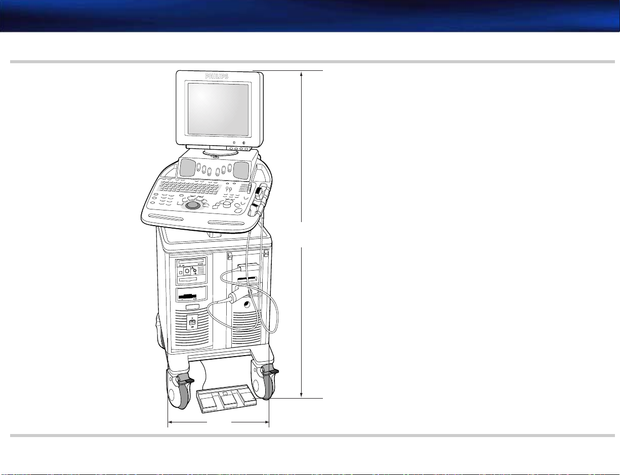
Physical
The tables and diagrams that follow detail the physical specifications of the M2540A.
Dimensions
Table 2-1 Physical Specifications
Parameter Specification Reference
Dimensions
Depth (front to back) 103 cm (40.5 inches) See Figure 2-2
Width 53.5 cm (21 inches) See Figure 2-1
Height (to monitor top) Lowest position: 129.5 cm (51 inches)
Highest position: 147.5 cm (58 inches)
Height of lower enclosure 76.2 cm (30 inches) See Figure 2-2
Monitor to control panel front edge 43.18 cm (17 inches) See Figure 2-2
Monitor depth
(front to back)
Weight Less than 91 kg (200 lbs) including display but no peripherals See Figure 2-2
Environmental Operational
41.71 cm (16.42 inches) See Figure 2-2
Temperature range: 0° to 40° C
Relative humidity: 20% to 80%
Atmospheric pressure: 572hPa to 1013 hPa
(VCR and printers temperature limit: 0° to 40° C at 80% RH)
See Figure 2-1
Storage
Temperature range: –40° to 55° C
Relative humidity: 20% to 90%, non-condensing
Atmospheric pressure: 572hPa to 1013 hPa
Page 15
M2540-92000-01 A M2540 Ultrasound System Field Service Manual Page 15
Specifications: Physical Dimensions
Figure 2-1 System Front Dimensions
-
+
-
+
Range:
129.5 cm (51 in) -
147.5 cm (58 in)
.
.
.
.
.
.
.
.
.
.
.
.
53.5 cm
(21 in)
Page 16
M2540-92000-01 A M2540 Ultrasound System Field Service Manual Page 16
Specifications: Physical Dimensions
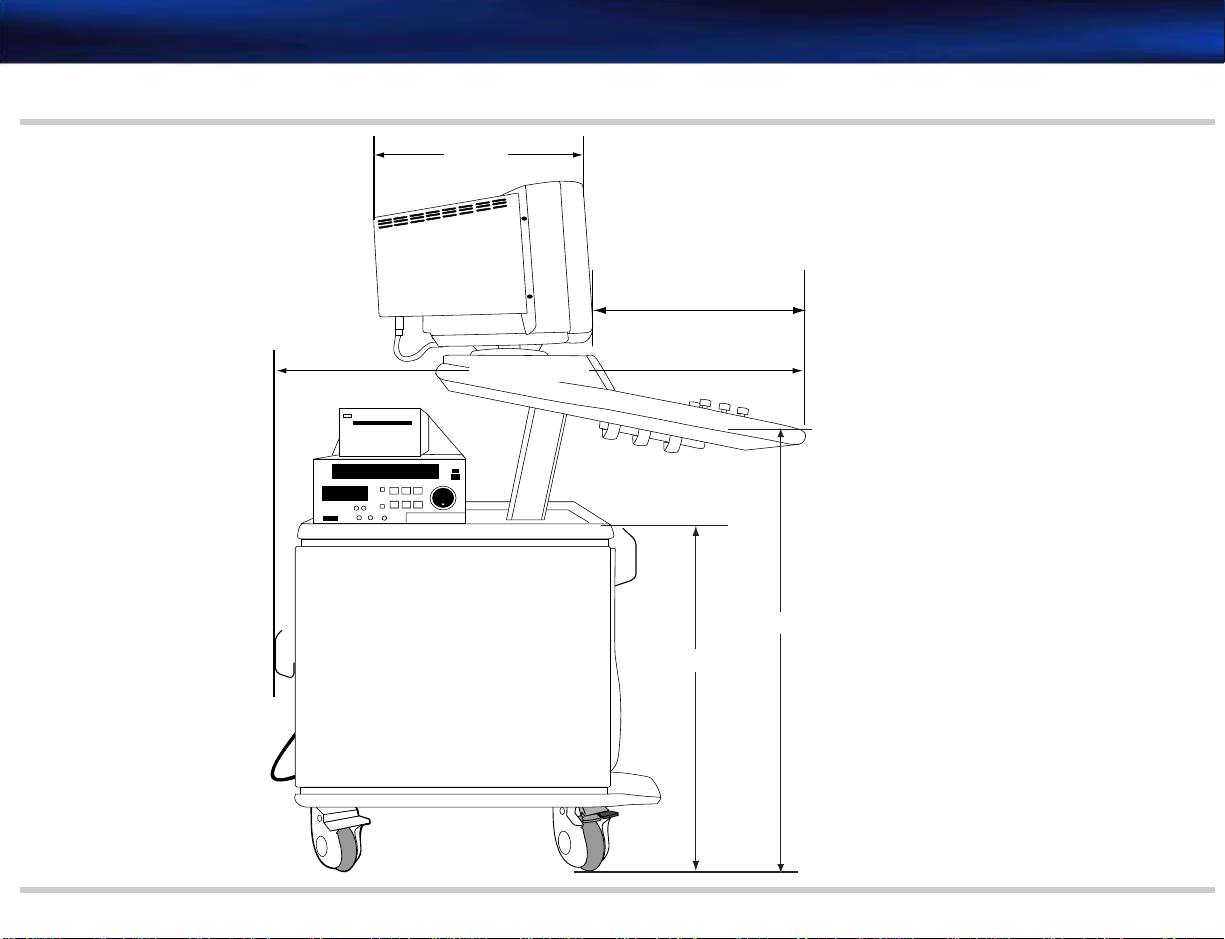
Figure 2-2 System Side Dimensions
41.71 cm
(16.42 in)
43.18 cm (17 in)
99 cm (39 in)
95.25 cm (37.5 in)
74.3 cm (29.25 in)
Page 17
M2540-92000-01 A M2540 Ultrasound System Field Service Manual Page 17
Specifications: Physical Dimensions
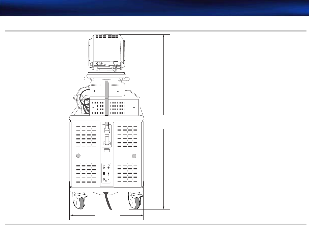
Figure 2-3 System Rear Dimensions
Range:
129.5 cm (51 in) -
147.5 cm (58 in)
53.5 cm (21 in)
Page 18
M2540-92000-01 A M2540 Ultrasound System Field Service Manual Page 18
Specifications: Physical Dimensions
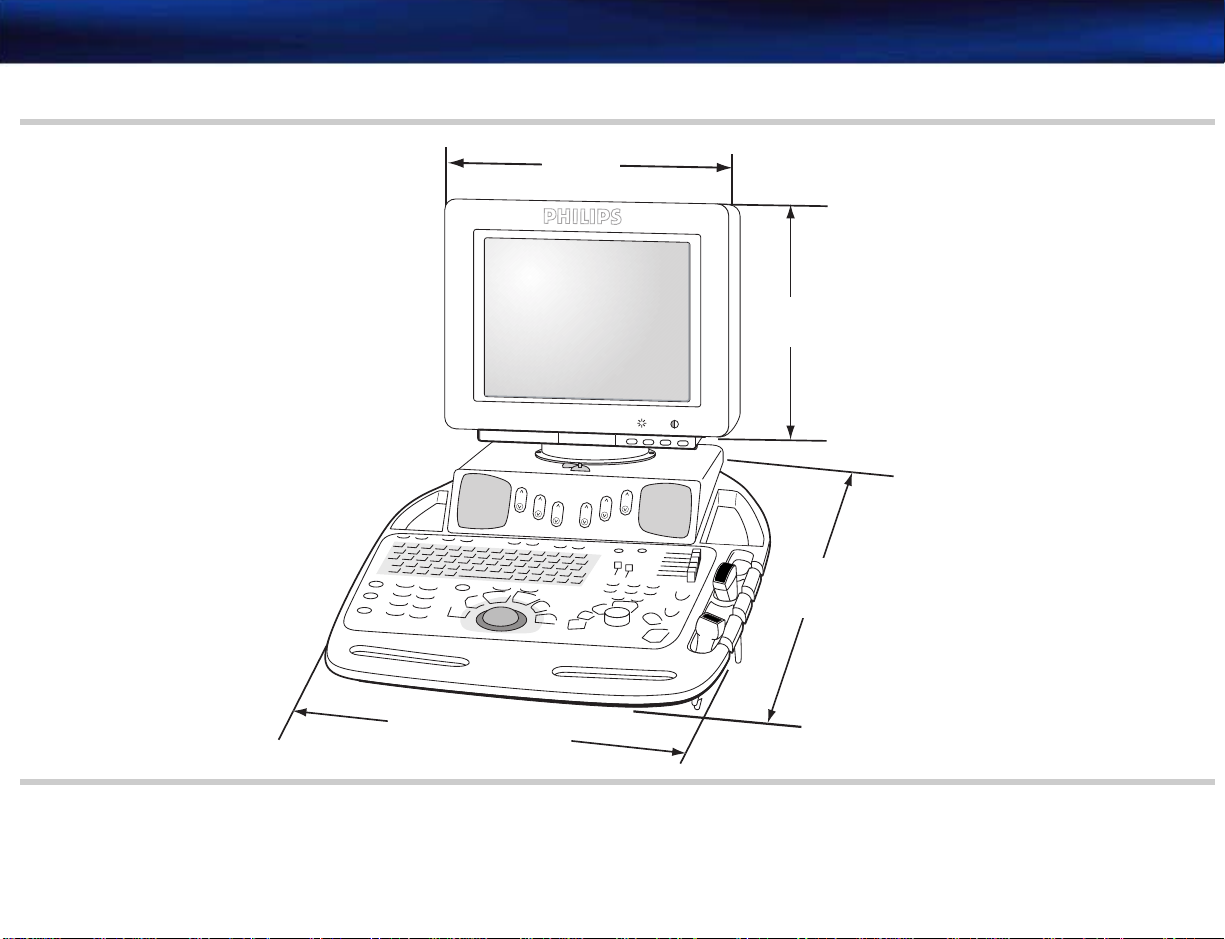
Figure 2-4 System Top Dimensions
39.4 cm
(15.5 in)
33 cm
(13 in)
-
+
-
+
72.6 cm
(28.5 in)
53.45 cm (21 in)
Page 19

M2540-92000-01 A M2540 Ultrasound System Field Service Manual Page 19
Specifications: Electrical Specifications
Electrical Specifications
Monitor
Table 2-2 Electrical Specifications
Parameter Specification
AC input 90 VAC to 264 VAC, 47 Hz to 63 Hz
Ground impedance 200 milliohm maximum
Dielectric withstand 1500 VAC mains to safety ground
2000 V mains to AC secondaries
4000 V mains to DC secondaries
Load 1150 VA maximum.
AC output 120 VAC, 60 Hz, quasi square-wave, 500 VA maximum
Table 2-3 Main Display
Parameter Specification
Screen size 15-inch diagonal
Display format VGA, 800x600
75 Hz refresh rate
RGB color display
Features Tilt ±30 degrees
Swivel ±135 degrees
Page 20

M2540-92000-01 A M2540 Ultrasound System Field Service Manual Page 20
Specifications: Transducer Specifications
Transducer Specifications
The following table lists the specifications of the transducers that the M2540A supports.
Table 2-4 Transducers
Part
Description
1
S4
Number Frequency Connector
21330A Cannon
S8 21350A Cannon
S12 21380A Cannon
c
3540 biopsy capable 1
21321A 3.5 MHz Cannon
EC6509 endocavity 21336A Cannon
L7535 linear
21359A 7.5 MHz Cannon
TEE (Omni II) 21369A 6 MHz Cannon
L1038A small parts 21376A Cannon
15-6L intraoperative 21390A Cannon
PA 4-2 biopsy capable 21422A 2 to 4 MHz Advance Vision
CA 5-2 21425A 2 to 5 MHz Advance Vision
D1914c 21221B 1.9 MHz Pencil
1. This transducer is compatible with the M2540A, but is only sold separately.
Page 21

M2540-92000-01 A M2540 Ultrasound System Field Service Manual Page 21
Specifications: Connection and Communication Specifications
Connection
and Communication
Specifications
System I/O Por ts
The following tables list the communication and connector specifications of the M2540A.
PC Ports
The following table lists the ports on the rear of the internal PC and describes their locations.
Table 2-5 PC Ports
Port Specification
Composite video output
(optional)
S-Video output (optional)
S-Video input (optional)
1
1
1
Print trigger output 3.5-mm phone jack on APIO board
VCR audio output (line out)
(optional)
VCR audio input (line in)
1
1
Female phono (RCA) on TV and video converter board
4-pin mini circular DIN on SVGA to TV video card
4-pin mini circular DIN on video capture card
Green 3.5-mm stereo phone jack on sound card
Blue 3.5-mm stereo phone jack on sound card
Microphone Pink 3.5-mm stereo phone jack
Speakers Green 3.5 mm stereo phone jack to system speaker amplifier
Monitor 15-pin D connector on graphics adapter board
Foot switch 9-pin female D-sub connector on the APIO board that carries
foot switch signals from the external I/O panel
Page 22

M2540-92000-01 A M2540 Ultrasound System Field Service Manual Page 22
Specifications: Connection and Communication Specifications
Table 2-5 PC Ports (Continued)
Port Specification
Com 1 9-pin D connector, RS-232; spare serial port used for serial
VCRs
Keyboard DIN circular connector
Mouse DIN circular connector
Token ring 50-pin connector on the APIO board
LAN RJ-45 to I/O panel for network communication
USB USB (A) for data and power to system control panel
USB For black-and-white thermal printer
USB For color printer
USB For remote plain-paper printer
PS-2 keyboard Not used
PS-2 mouse Not used
Parallel port Not used
Audio input on main board Not used
1. Only available with VCR option or external video/print option
Page 23

M2540-92000-01 A M2540 Ultrasound System Field Service Manual Page 23
Specifications: Physio Port Specifications
I/O Panel Ports
Physio Port Specifications
The following table lists the ports on the I/O panel and the signals they carry.
Table 2-6 I/O Panel Ports
Port Connector Signal
Composite video BNC Composite video signal from SVGA board
Foot switch D-sub 9 Control signal from foot switch to APIO board
Defaults are: record, freeze, and record 2
Each signal is a contact closure to ground, active low, and
TTL compatible
Print BNC Trigger signal from APIO board
LAN RJ-45 Communication with local area network
The following table lists the specifications of the M2540A’s physio ports.
Table 2-7 Physio Port Specifications
Port Specification
ECG 3 patient leads with R-wave detection
Monitoring quality only
Frequency response: 1 ±0.5 to 30 ±6 Hz
Audio/Video Specifications
Sensitivity: 3 mVpp ±2.5 mV for full scale at 100% gain
Aux 1 3-dB bandwidth: full scale DC to 100 Hz minimum
Maximum input signal: ±4 V
Sensitivity: 2.5 ±0.5 Vpp for full scale at 100% gain
The following tables list the audio and video specifications of the M2540A.
Page 24

M2540-92000-01 A M2540 Ultrasound System Field Service Manual Page 24
Specifications: Audio/Video Specifications
Audio
Table 2-8 Audio Specifications
Description Specification
Speakers Stereo—VCR, Doppler
Doppler spectrum toward transducer — left speaker
Doppler spectrum away from transducer — right speaker
Maximum power input: 4 watts
Impedance: 8 ohms
External Video
Frequency
Response
Microphone Faces front. 10 Hz to 20 KHz electret type
Table 2-9 External Video Specifications
Description Specification
Color Composite NTSC 3.58 (USA), PAL 4.43 (Europe)
Print Trigger 1 signal from the APIO board
130 Hz to 12 KHz
1.0 V p to p ±5% into 75 ohms (only with VCR option)
Active low: ON = 0.5 V max @ 1 mA; OFF = 5.25 VDC maximum
voltage
Page 25

M2540-92000-01 A M2540 Ultrasound System Field Service Manual Page 25
Specifications: Audio/Video Specifications
Video Output Specifications
Table 2-10 Video Output Specifications
Output Specification
RGBSync to system
0.7 Vpp RGB with TTL sync
monitor
S-Video Output to
VCR
1.0 Vpp luminance incorporating sync and 0.3 Vpp chrominance as
shown in Ta bl e 2 -9 . This timing is essentially RS-170 (60 Hz) or CCIR
(50Hz) video timing.
Page 26

M2540-92000-01 A M2540 Ultrasound System Field Service Manual Page 26
Safety:
3Safety
This section provides an overview of safety considerations for the ultrasound system. These
safety concerns apply to patients, operators, and service engineers. For more detailed safety
information, see the Philips Safety and Standards Guide.
The following topics are included in this section:
• “Transmit Power (Acoustical)” on page 27
• “Acoustic Exposure” on page 27
• “AIUM/NEMA Output Display Standard” on page 28
• “Explosive Hazards” on page 30
• “Electrical Warnings” on page 31
• “Peripheral Connections” on page 31
• “Glutaraldehyde Exposure” on page 32
• “Moving the System” on page 32
• “Electromagnetic Compatibility” on page 35
• “Restrictions for Use” on page 36
• “Electrosurgical Units” on page 37
Page 27

M2540-92000-01 A M2540 Ultrasound System Field Service Manual Page 27
NOTES
Safety: Transmit Power (Acoustical)
Tr a ns m i t Power (Acoustical)
Acoustic output, expressed as an index, is displayed on the screen to allow the best possible
diagnostic image with minimal power output. A display standard presents this index using one of
the following four power indices:
• Mechanical index (MI)
• Thermal index for soft tissue (TIS)
• Thermal index for bone (TIB)
• Thermal index for cranial bone (TIC)
The index setting on the System Setup menu selects the power index used. The displayed
index is based on this setting and on preset configuration and imaging mode.
• The power index setting on the System Setup menu selects any of the four power indices
for display at any time.
• The Powe r rotary control at the right side of the system control panel is the only control
that affects transmit power level.
For additional information on acoustical power settings and power index, see the Philips Safety
and Standards Guide.
Acoustic Exposure
Although no harmful effects have been demonstrated for any of the ultrasound frequencies,
intensities, and exposure times used in examinations with Philips ultrasound systems, Philips
recommends that you consider the following, and use the lowest ultrasound exposure that
produces diagnostically acceptable information:
• Use diagnostic ultrasound only when there is a good medical reason.
• Reset the controls at the start of every examination.
Page 28

M2540-92000-01 A M2540 Ultrasound System Field Service Manual Page 28
Safety: AIUM/NEMA Output Display Standard
• Reduce exposure time, independent of acoustic index value.
• Use techniques that let you collect clinical data quickly and end the examination promptly.
• Select a transducer that provides good resolution and focal depth for the region of interest.
Then use the imaging controls to fine-tune image resolution.
For more detailed information on acoustic exposure, see the Output Display Standards and ODS
Acoustic Tables booklet.
AIUM/NEMA Output Display Standard
In compliance with the Output Display Standard (ODS) jointly proposed by the American
Institute of Ultrasound in Medicine and the National Electrical Manufacturers Association, the
Philips ultrasound system displays power output indices related to the potential for bioeffects.
Real-time information related to the power output is displayed on the monitor, indicating the
type of index displayed and the value of that index for the acoustic output currently being used.
For example, if the output corresponds to a mechanical index of 0.8, the following is displayed:
MI: 0.8
The displayed index is one of four types: MI, TIS, TIB, or TIC. These ultrasound abbreviations
conform to the AIUM/NEMA Output Display Standard.
Soft tissue thermal index (TIS) is used in cardiac, fetal, and abdominal scanning.
The thermal index for bone (TIB) is used in applications such as second or third trimester fetal
scanning and neonatal cephalic (through the fontanelle) scanning.
The cranial bone thermal index (TIC) is used for transcranial imaging.
Page 29

M2540-92000-01 A M2540 Ultrasound System Field Service Manual Page 29
Safety: AIUM/NEMA Output Display Standard
NOTE The power index displayed on the screen depends on the preset type, the active
transducer type, the imaging mode, and the selected power index. Any of the four
power indices is selectable for display at any time, using the power index setting in the
System Setup menu.
Automatic Index Selection
For automatic selection of a power index based on system mode, the user selects the power
index setting of Normal from the System Setup menu. This directs the system to choose an
index based on the active preset and imaging mode.
When MI is Displayed With the Normal Setting
MI is displayed if any of the following conditions exist:
• 2D Only is the active imaging mode.
• Black-and White MMode Preview is the active imaging mode.
• Black-and White Doppler Preview is the active imaging mode.
• Black-and White Doppler 2D Live is the active imaging mode.
When TIS is Displayed With Normal Setting
If none of the conditions in “When MI is Displayed With the Normal Setting” on page 29 exist, if
no transcranial preset is active, and any of the following conditions exist, TIS displays:
• Color is turned on.
• Angio is turned on.
• MMode Trace is the active imaging mode.
• Doppler Spectral is the active imaging mode (with 2D Live off).
Page 30

M2540-92000-01 A M2540 Ultrasound System Field Service Manual Page 30
Safety: Explosive Hazards
When TIC is Displayed With Normal Setting
If none of the conditions in “When MI is Displayed With the Normal Setting” on page 29 exist, a
transcranial preset is active, and any of the following conditions exist, TIS displays:
• Color is turned on.
• Angio is turned on.
• MMode Trace is the active imaging mode.
• Doppler Spectral is the active imaging mode (with 2D Live off).
If the user selects an ODS setting other than Normal, the selected index type is used as the
preferred acoustic power display format, regardless of the mode, the transducer, or the preset
that is selected.
The displayed index value does not provide an exact value of the potential for adverse bioeffects
in the patient. However, for any patient, the higher the value, the higher the potential for adverse
bioeffects. The user can minimize the potential for bioeffects by keeping the index value as low as
possible, by choosing the right transducer and making adjustments. Minimizing examination time
also minimizes bioeffects.
WAR NING
Explosive Hazards
The ODS power index formulas were defined for reasonable worst case patient conditions. It is
likely that a particular patient's actual conditions are better than indicated by the index. The
operator should be aware of patient conditions that mitigate the actual exposure.
Observe the following practices to avoid explosive hazards:
• Do not operate the system in the presence of flammable anesthetics.
Page 31

M2540-92000-01 A M2540 Ultrasound System Field Service Manual Page 31
Safety: Electrical Warnings
• When using the imaging system in the operating room, do not switch system power on or
off. Be sure system power is on before the operation starts, and leave it on for the duration
of the procedure.
WAR NING
Electrical Warnings
WAR NINGS
Peripheral Connections
Do not use the foot switch in the operating room.
Observe the following precautions to prevent electric shock:
• Only qualified service personnel should remove system covers (trim and service panels).
Accidental contact with electrical circuits inside the system could cause serious injury.
• Use only the power cords supplied with the system, and connect them only to properly
grounded electrical outlets.
• Failure to follow these warnings can affect both patient and operator safety.
• Do not connect the ultrasound system to the same circuit used for life support devices.
Peripherals (such as a VCR or a printer) typically meet general electrical safety usage
requirements, but do not meet medical device standards. Therefore, do not use system
peripherals within six feet of a patient unless the peripherals receive power from an isolated
power outlet on the imaging system, or from an isolation transformer that meets medical safety
standards. The 120 VAC outlets on the power supply are isolated. The specific peripherals listed
in “Optional Peripherals” on page 201 meet medical device standards when installed in the
system as recommended.
Page 32

M2540-92000-01 A M2540 Ultrasound System Field Service Manual Page 32
Safety: Glutaraldehyde Exposure
Glutaraldehyde
Exposure
Moving the System
The United States Occupational Safety and Health Administration (OSHA) has issued a
regulation dealing with levels of acceptable glutaraldehyde exposure in the working environment.
Philips does not sell glutaraldehyde-based disinfectants with its products. However, this type of
disinfectant is recommended for disinfection of transesophageal (TEE) or endocavity
transducers.
To minimize exposure to glutaraldehyde fumes, make sure the area is well ventilated and use
appropriate eye and skin protection.
Although the system is designed to be mobile, remember that it is very heavy, and that you
must take precautions when moving the system.
The ultrasound system has been designed to be as lightweight and mobile as possible. However,
the system weight—including the weight of the monitor, a printer, and a +VCR—is
approximately 100 kg (220 pounds). Because of this weight, you must use caution when moving
the system, since the ability to move any ultrasound machine is directly related to an individual’s
size and strength.
Some sonographers, particularly those weighing less than 100 pounds, have stated that they
injured their backs moving similar systems. These complaints could not be directly tied to one
particular incident. They do, however, point out the need to be careful in transporting medical
equipment such as an ultrasound system.
Before Moving the System
To move the system, take the precautions listed in the following sections, and
• Before moving the system, be sure to remove any loose equipment from the top of the system, disconnect the system power cord, and disconnect all external devices.
• Before transporting the system in a vehicle, remove the monitor and all transducers from the
system and put them in a packing box.
Page 33

M2540-92000-01 A M2540 Ultrasound System Field Service Manual Page 33
Safety: Moving the System
When Moving the System
WAR NING
Moving on Ramps or Uneven Surfaces
This system is equipped with a front handle and brakes on the front wheels.
Always use the handle at the front of the cart to move the system from place to place.
Never strap or secure the system at any point above the peripheral tray.
NOTE Use caution and follow these steps when moving the system from patient to patient.
1. Unlock the wheel locks before moving the system.
2. Make sure the control top is locked, to prevent its pivoting during transport.
3. Engage the track locks on the front wheels to ease straight-line travel.
4. Push with the handle at the front of the cart.
5. After the system is in position, engage the wheel locks to immobilize the system, and unlock
the control top to allow it to pivot.
Do not move the system over uneven elevator entrances by lifting the machine or any part of the
machine.
Always use two people when moving the ultrasound system up and down ramps longer than 20
feet or steeper than 5 degrees. (Wheelchair ramps are usually less than 5 degrees.) Avoid ramps
that are steeper than 10 degrees, to eliminate the danger of the system tipping over.
System Tilting
The system has been tested for stability using the IEC 60601-1 test protocol. Following this
protocol, the system will not tip over on an incline of up to 10 degrees in any direction. When
this amount of incline is exceeded, there is a potential for the system to tip over.
Page 34

M2540-92000-01 A M2540 Ultrasound System Field Service Manual Page 34
Safety: Moving the System
WAR NING
Transporting the System in a Vehi cle
WAR NING
Use care when tilting the system for an incline. The amount of incline allowable to prevent
tip-over is 10 degrees. Moving the system over a roadside curb or other small but steep incline
can cause the system to exceed 10 degrees of incline.
Always engage the wheel locks while transporting the system in a vehicle, and use restraining
straps to secure the system in place. Do not rely on the wheel locks to hold the system on
inclines greater than 5 degrees.
Be sure that the transporting vehicle can handle the weight of the system (or systems) plus the
passengers.
Be sure the load capacity of the loading lift can accommodate the weight of the ultrasound
system. A minimum capacity of 550 pounds is recommended.
Always secure the ultrasound system while it is on the loading lift so that it cannot roll. Make
sure the control top is locked, to prevent its pivoting. Engage the wheel locks and use wood
chocks, restraining straps, or other similar types of constraints as an added safety measure. Do
not attempt to hold the system in place manually.
Never strap or secure the system at any point on the control top or monitor.
Load and unload the ultrasound system while the transporting vehicle is parked on a level
surface. The system’s weight can easily cause it to roll on any incline.
The system’s weight on an extended loading lift may cause the transporting vehicle to tilt, which
could cause personal injury or system damage.
Page 35

M2540-92000-01 A M2540 Ultrasound System Field Service Manual Page 35
Safety: Electromagnetic Compatibility
WAR NING
Electromagnetic
Compatibility
Avoiding
Electromagnetic
Interference
Never ride on a loading lift with the system. Your weight combined with the system's weight can
exceed the lift's load capacity.
Be sure the ultrasound system is firmly secured while inside the transporting vehicle. Any
movement, combined with the system’s weight, could cause the system to break loose.
NOTE If you use the ultrasound system in a mobile van, follow the same fundamental
transporting precautions listed in the sections above.
This system has been tested for electromagnetic compatibility (EMC) according to the
international standard for EMC with medical devices, as determined by the International
Electrotechnical Commission (IEC 60601-1-2). This IEC standard has been adopted in Europe as
the European Norm EN 60601-1-2.
Medical devices can generate or receive electromagnetic interference (EMI). The EMC standards
describe tests for both emitted and received interference. Emission tests deal with interference
generated by the device being tested. The Philips ultrasound system does not generate
interference based on the tests described in the standards.
Ultrasound systems are designed to receive radio frequency (RF) energy and are therefore
susceptible to EMI generated by other RF energy sources. Examples of other sources of EMI are
medical devices, information technology products, and radio and television transmission towers.
Tracing the source of radiated interference can be a difficult task.
See “Electromagnetic Interference” on page 137 to identify sources of EMI.
Only a physician can determine if an artifact caused by radiated interference has a negative
impact on image quality and the subsequent diagnosis.
Page 36

M2540-92000-01 A M2540 Ultrasound System Field Service Manual Page 36
Safety: Restrictions for Use
Restrictions for Use
Immunity Level Test Results
The M2540A ultrasound system is subject to certain restrictions that are described in the
following sections.
The EMC standards require that manufacturers of patient-coupled equipment specify
electrostatic discharge immunity levels for their systems. This type of device is designed to
receive and amplify low-level signals in the same bandwidth as the interference to which it is
susceptible.
Immunity is defined in the standard as the ability of a system to perform without degradation in
the presence of an electromagnetic disturbance. Degradation in image quality is a qualitative
assessment that can be subjective. The simplest way to assess degradation is to note when the
first sign of an artifact is seen. This method has two advantages: It removes the issue of subjective
decision-making and provides the most stringent test results.
Caution should therefore be taken in comparing immunity levels of different ultrasound systems.
The criteria used for measuring degradation are not specified by the standard, and can vary with
the manufacturer.
Philips has tested each class of transducer for every operating mode over a wide range of
frequencies. This testing showed PW Doppler to be the most susceptible to radio-frequency
interference.
Electrostatic Discharge
Please see the Philips Safety and Standards Guide shipped with your system for additional
information about compliance with EMC standards.
Electrostatic discharges can cause the ECG heart rate display to increase by 10 to 15% for a few
seconds after the discharge. However, the ECG heart rate display returns to normal within four
seconds.
Page 37

M2540-92000-01 A M2540 Ultrasound System Field Service Manual Page 37
Safety: Electrosurgical Units
Electrosurgical Units
Electrosurgical units (ESUs) and other devices intentionally introduce radio frequency
electromagnetic fields or currents into patients. Because imaging ultrasound frequencies are also
in the radio frequency range, ultrasound transducer circuits are susceptible to radio frequency
interference. While an ESU is in use, the noise generated severely interferes with the
black-and-white image and completely obliterates the color image.
Page 38

M2540-92000-01 A M2540 Ultrasound System Field Service Manual Page 38
Theory of Operation: Overview
4 Theory of Operation
Overview
This section provides a technical overview of system functions. The discussion focuses on the
main functions and features of the system’s PC, circuit boards, and power distribution. Main
system functions are also shown in the functional block diagrams at the end of this section.
The M2540A’s internal PC replaces the back-end electronics used in earlier ultrasound systems
to handle display processing. The beam processor/acoustic processor (BPAP) board handles the
acoustic and beam processing front-end functions.
This section covers the following areas of the system:
• “Internal PC” on page 39
• “TR Boards” on page 40
• “BPAP Board” on page 42
• “Demodulator Board” on page 43
• “APIO Board” on page 43
• “Physio Module Option” on page 43
• “System Motherboard” on page 44
• “Distribution Board and Connector Modules” on page 44
• “I/O Panel” on page 45
• “System Control Panel” on page 45
• “Power Supply” on page 46
• “Functional Block Diagrams” on page 47
• “Transducer Safety Testing: Test Setup and Theory” on page 52
Page 39

M2540-92000-01 A M2540 Ultrasound System Field Service Manual Page 39
Theory of Operation: Internal PC
Internal PC
Standard PC Components
The M2540A uses an internal PC to coordinate and perform many of the functions that required
dedicated circuit boards in earlier ultrasound systems. The power button on the front of the PC
is the system power switch. Turning on the PC starts the ultrasound system.
The M2540A’s internal PC contains the following standard components:
• A motherboard
• A hard drive
• A graphics card in the AGP slot
• The Acoustic Processor I/O (APIO) board, in a PCI slot (See “APIO Board” on page 43)
• A 3
1
-inch floppy disk drive
/
2
• A CD-RW drive
PC Ports
The PC motherboard’s ports are used as follows:
• A USB port communicates with the system control panel.
• A USB port communicates with an optional black-and-white thermal printer.
• A USB port communicates with an optional color printer.
• A USB port communicates with an optional plain-paper printer.
• A USB port communicates with the optional physio module.
• A LAN port connects the PC to a network.
• A 3.5 mm phono jack receives audio signals from a microphone.
• A 3.5 mm phono jack supplies the signal that drives the system’s speakers.
• An RS-232 port (Com1) controls an optional VCR.
Page 40

M2540-92000-01 A M2540 Ultrasound System Field Service Manual Page 40
Theory of Operation: TR Boards
VCR-Option Components in the PC
The VCR option includes several cards inside the PC and an adapter that connects to the SVGA
output of the PC’s graphics adapter board. See Figure 4-1 on page 48 for a detailed
representation of how the VCR option’s components function in the ultrasound system.
The following cards are part of the VCR option, and reside in the PC’s PCI slots:
• A sound card that receives audio from the VCR, and supplies sound to the VCR
• A video capture board that receives S-Video signals from the VCR
• An SVGA-to-S-Video card that converts the SVGA signal from the graphics adapter board (in
the AGP slot) to S-Video for the VCR
• An SVGA adapter that connects the graphics adapter board to the SVGA-to-TV video card
and to the monitor
See “VCR Option Parts” on page 198 for a list of all the components of the VCR option.
Optional Drive-Bay Components
The PC’s drive bays accept the following components:
TR Boards
• The Physio module that provides ECG monitoring capability. The drive bay’s power connec-
tor powers the module, but the module does not use the drive bay’s data port. The module
communicates with the ultrasound system through a USB cable to the PC motherboard. See
“Physio Module Option” on page 43, and Figure 4-3 on page 51 for detailed information on
the Physio module.
• A magneto-optical disk (MOD) drive that allows archiving of images, studies, and reports on
removable disks. The MOD uses the drive bay’s data and power ports.
The M2540A’s e-box contains two transmit-and-receive (TR) boards. Each has a connector that
plugs into the motherboard and another connector that passes through the motherboard and
Page 41

M2540-92000-01 A M2540 Ultrasound System Field Service Manual Page 41
Theory of Operation: TR Boards
plugs into the distribution board. The two boards form electronic beams of the transmit and
receive signals. Each TR board contains 64 transmitters and 32 preamps multiplexed into 64
receive channels. This allows multiplexing the system’s 64 active channels into 128 element
arrays. Each receive channel consists of time gain compensation (TGC) amplifiers, low pass
filters, 10-bit A/D converters, and one eighth of a digital beam-forming circuit. Each TR board
sends on its output bus a value that is the sum of the data from its 32 channels plus its 18-bit
input bus. The last TR board in this chain outputs the final summed radio-frequency (RF) data to
the demodulator board.
The transmit and receive beam-forming coefficients for acoustic lines are downloaded on the
coefficient bus from the BPAP board.
The BPAP board generates the timing to start and stop each firing line, and sends the transmit
signal to the TR board, through the distribution board and the connector modules to the
transducer. Analog drivers generate the transmitted RF data. A digital timing generator delays
and times each of the analog drivers. The delay generators receive the appropriate delay values
from the BPAP for each channel. The system power supply controls the amplitude of the
transmitted waveform.
The received signal is preamplified, TGC amplified, low-pass filtered, and digitized (in all modes
except CW). The BPAP board generates TGC control signals through the demodulator board.
After being digitized, the signal on each line is delayed appropriately. The outputs of all channels
are daisy-chained together to sum the outputs. The RF data output of one TR board is the input
to the next TR board, and the outputs of the TR boards are summed to form the received beam.
The summed output signal (RF DATA) goes to the demodulator board.
The CW Doppler signal is mixed to an analog intermediate frequency (IF) signal. The CW
Doppler output is a single differential signal routed to the demodulator board.
Page 42

M2540-92000-01 A M2540 Ultrasound System Field Service Manual Page 42
Theory of Operation: BPAP Board
BPAP Board
Omni TEE Circuitry
The beam processor/acoustic processor (BPAP) board contains two processors. One of them
controls beam-forming, line-to-line operation. The other handles the processing of scan
conversion, color flow, and Doppler signals.
The BPAP board does the following:
• Provides the interface between the PC and the TR boards
• Provides the interface between the PC and the demodulator board
• Receives control data sets from the PC, processes them for specific register values, and
sends them to the TR boards
• Houses the transesophageal echo cardiography (TEE) transducer interface circuitry (TEE
motor control and temperature monitoring)
• Houses the transducer ID circuitry
• Detects the presence of standalone transducers
• Houses electronic switching that allows selection of a single active transducer from the four
that can be connected
• Controls the high-voltage output from the system power supply
The Omni Probe control circuitry on the BPAP board supplies power to the TEE transducer's
motor. It also measures the position of the angle-position sensor. The signal is digitized and sent
to the APIO board for monitoring by the PC.
The beam processor circuitry monitors thermistors in the transducer and insures that high
voltage is not applied to the transmitter unless the thermistor values are within limits.
Page 43

M2540-92000-01 A M2540 Ultrasound System Field Service Manual Page 43
Theory of Operation: Demodulator Board
Demodulator Board
APIO Board
The demodulator board performs image and Doppler demodulation for BMode, MMode, PW
and CW phased and non-imaging Doppler modes, and color flow mode. It sends a baseband data
stream to the BPAP board.
The demodulator board contains the following:
• Digital filters and mixers for demodulating 2D, color flow, and PW RF data
• The independent transducer CW Doppler electronics and steerable CW detector functions
• The 120 MHz system clock. The clock signal is distributed to the TR and BPAP boards.
• Circuitry that generates TGC signals
The acoustic processor I/O (APIO) board is the token ring interface between the system’s PC
and the e-box. The APIO board also handles input from the foot switch’s three control buttons
(via the I/O panel) and forwards them to the PC. The board also generates trigger signals for
legacy printers.
The board handles these signals from the PC:
• The R-wave pulse from the physio module that it sends to the BPAP board
• The DC on-off bit that it sends to the power supply
• Commands that program the BPAP board at startup
Physio Module Option
• Acoustic data from the BPAP board for the acoustic imaging display
The self-contained Physio module resides in one of the PC’s drive bays. The module receives
power from the drive bay’s power connector, but it communicates with the system through a
USB cable to the PC’s motherboard. A shielded and grounded enclosure prevents
electromagnetic interference. See Figure 4-3 on page 51 for a detailed representation of the
module’s functions and connections.
Page 44

M2540-92000-01 A M2540 Ultrasound System Field Service Manual Page 44
Theory of Operation: System Motherboard
Primary Functions
Connectors
System Motherboard
Distribution Board and Connector Modules
The module’s primary functions are as follows:
• Process electrocardiogram (ECG) signals from patient electrodes and deliver the data to the
M2540A’s PC
• Send a detected R-wave trigger to the APIO board for frame triggering in various scanning
modes
• Provide gain control for ECG waveforms
The Physio module has two connectors on its front panel:
• The ECG-input connector is a round, 12-pin connector that is isolated from chassis ground.
• A ¼-inch phone plug jack accepts auxiliary input and has both signal and shield grounds.
This board connects all data paths between the TR boards, the BPAP board, and the distribution
board. It is also the distribution point for DC power and ground to all boards (the BPAP board
and distribution board also receive power directly from the system power supply.). It also sends
filtered high voltage to the TR boards.
The distribution board passes transducer signal inputs to the imaging system. The system power
supply provides high voltage directly to the distribution board to fire transducers.
Signals that pass through this board include
• Transducer identification signals from the BPAP board to and from the transducer
• Transmit and receive signals from the TR boards to the active transducer
• TEE motor-control and temperature-sense signals from the BPAP to and from the TEE trans-
ducer
Page 45

M2540-92000-01 A M2540 Ultrasound System Field Service Manual Page 45
Theory of Operation: I/O Panel
Tr a ns d u ce r Connector Module Types
I/O Panel
System Control Panel
The four transducer module bays accept the following types of modules in any combination:
• Cannon connector
• Advance Vision connector
• Pencil-type transducer connector
• Blank module
See Table 13-2 on page 179 for a list of the modules and their part numbers.
The I/O panel bears four connectors and two ground points. The main system ground used for
safety testing, and an equipotential post are the two ground points on the panel.
The I/O panel’s connectors are
• An RJ-45 (CAT 5) connector for connection to a LAN
• A BNC connector that carries composite video signals for a legacy printer
• A BNC connector that carries trigger signals for a legacy printer
• A 9-pin D connector for the optional foot switch
The system control panel contains the circuitry to process control inputs, the system keyboard,
rotary and slide controls, and the trackball. A USB cable carries control inputs from the control
panel to the PC. An auxiliary cable carries power from the system power supply. The system
control panel circuit board also carries the amplifiers for the system’s stereo speakers.
All control inputs and LEDs are controlled by the system’s PC, and their functions are
determined by resident control-panel and system software.
Circuit boards inside the system control panel are not field serviceable or replaceable. The
entire assembly, including circuit boards, bezel assembly, and labels, is available as a replaceable
Page 46

M2540-92000-01 A M2540 Ultrasound System Field Service Manual Page 46
Theory of Operation: Power Supply
part. Rotary and sliding knobs, rotary encoders for the knobs, the trackball assembly, and the
trackball cable are all available as separate parts.
Power Supply
The M2540A power supply is a self-contained unit that accepts AC input from 90 to 264 V, at 50
or 60 Hz, and supplies 120 VAC at 60 Hz to the system’s PC, monitor, and two peripherals. It
also provides all DC power required by system components. No switch settings are required to
configure the power supply for different AC mains; the power supply automatically adjusts to use
the power connected to it. Except for the 120 VAC to the PC, all power output is activated by a
signal from the PC. The system cooling fan is the only serviceable part on the power supply. See
Figure 4-1 on page 48 for details of the power supply’s outputs. The power supply activates when
it receives an “AWAKE_N” signal, which is generated by the PC, and then sent through the BPAP
board to the power supply.
The system power supply does the following:
• Provides DC power to all system electronics through the system motherboard and the BPAP
board
• Provides DC power directly to the system cooling fan
• Provides high voltage to the distribution board for multiplexing transducers
• Isolates AC mains from secondary AC and DC circuitry
• Transforms primary voltages to secondary voltages
• Filters line AC
• Provides an isolated 120 VAC unswitched outlet to power the internal PC
• Provides three isolated 120 VAC switched outlets to power the monitor and two peripherals
Page 47

M2540-92000-01 A M2540 Ultrasound System Field Service Manual Page 47
Theory of Operation: Functional Block Diagrams
Functional Block Diagrams
System Functional Block Diagram
This section contains block diagrams of the system’s components and their connections.
The section includes the following block diagrams:
• Figure 4-1 on page 48 shows the ultrasound system with the VCR option installed. This dia-
gram does not include the e-box or the system’s power supply. Those components are
shown in Figure 4-2 on page 49.
• Figure 4-2 shows the e-box and the system power supply and their connections to other
components of the ultrasound system.
• Figure 4-3 on page 51 shows the optional Physio module and its internal connections.
Figure 4-1 shows the M2540A system with the VCR option installed.
Page 48

M2540-92000-01 A M2540 Ultrasound System Field Service Manual Page 48
Theory of Operation: Functional Block Diagrams
Figure 4-1 System Block Diagram with VCR Option
Speaker Speaker
Floppy disk
drive
Optional
MO drive
CD-RW drive
Optional
Physio module
USB
Internal PC
R-wav
Hard disk drive
PC
motherboar
VCR option
sound board
VCR option
capture board
VCR option
converter
board
Graphics
adapter board
APIO board
PC power
Com
S-video
SVGA
adapter
Audio
USB
USB
USB
Audio
LAN
RS-232
Audio
S-video
Composite video
SVGA video
Trigger
Foot switch
To k e n r i ng
To e-box (see Figure 4-2)
System control panel
Microphone
Audio
I/O
panel
AC power
DC power
Optional printers
(up to 2)
Optional
VCR
Monitor
AC power
System power
supply
(see Figure 4-2
for detail)
To remote
USB printer
AC power
AC power
Page 49

M2540-92000-01 A M2540 Ultrasound System Field Service Manual Page 49
C
Theory of Operation: Functional Block Diagrams
e-box and Power
Supply
Figure 4-2 shows the system’s power supply and the e-box and their connections to each other
and other components.
Functional Block
Diagram
Figure 4-2 e-box and Power Supply Block Diagram
Distribution board
Motherboard
Connector
module
Connector
module
Connector
module
Connector
module
Fan
+11, +5
+60, -140
mux V
+12 VDC variable
±12, -5,
±HV
TR board
TR board
Demodulator board
BPAP board
+3, +5
VDC
+2 VDC
Power supply
Control
To APIO board in PC
Token ring
To PC
Unswitched
120 VAC
Switched 120 VAC
Switched 120 VAC
Switched 120 VAC
+5, +12, -12 VDC
To peripherals
To monitor
To system
control panel
90 - 264 VA
Page 50

M2540-92000-01 A M2540 Ultrasound System Field Service Manual Page 50
Theory of Operation: Functional Block Diagrams
Token Ring Cable
The token ring cable carries the following signals between the BPAP board and the APIO board:
• R-wave communication
• On and off signal that switches on the outputs from the power supply (the 120 VAC output
for the PC is always on)
• Program enable and program done (on separate circuits)
• Ring in and ring out (on separate circuits)
Page 51

M2540-92000-01 A M2540 Ultrasound System Field Service Manual Page 51
Theory of Operation: Functional Block Diagrams
Physio
Functional Block
Figure 4-3 shows how the Physio module functions, its internal connections, and connections to
other components.
Diagram
Figure 4-3 Physio Module Block Diagram
Isolated front end
Bandpass
0.35 to 30Hz
AUX In
clk24
ECG leads
Differential
amp
and
driver
Signal
isolation
Power
isolation
islout
Clock
divider
X216
filter
M
U
X
auxsel
Phy1 offset
gain adjust
Phy2 offset
gain adjust
nlddac2
EZ-USB
controller
and
and
dacdata
phy1
phy1
phy2
spi-do
spi-di
spi-ck
nadccs
R-wave
detector
A/D
converter
r-raw
dacdata
nlddac1
To APIO
R-wave trig
To PC motherboard
USB
Page 52

M2540-92000-01 A M2540 Ultrasound System Field Service Manual Page 52
Theory of Operation: Transducer Safety Testing: Test Setup and Theory
Transducer Safety Testing: Test Setup and Theory
This section provides background and supporting information for the transducer leakage tests in
Section 6, “Performance Tests”; this information is not required to perform the tests.
In transducer safety tests, a container filled with saline solution functions as a conductive
medium (see Figure 4-4 on page 53). The solution penetrates any faults in the transducer
insulation and provides an electrical path between the submerged lead wire and the grounded
inner transducer shield.
The test for transthoracic and endocavity transducers differs from the test for TEE transducers
only by the extent that the transducers are submerged in the test solution.
Page 53

M2540-92000-01 A M2540 Ultrasound System Field Service Manual Page 53
Theory of Operation: Transducer Safety Testing: Test Setup and Theory
Figure 4-4 Transducer Leakage Current Test Setup and Theory Diagram
See Key for
Figure 4-4
I
Hot
Neutral
Ground
Neutral condition:
Mode selector on safety analyzer:
Open Neutral button
Open Ground button
SAFETY ANALYZER
system
I
measured
A
Closed for normal condition
Closed for 1st single fault condition
Open for 2nd single fault condition
Ultrasound
metal chassis
C
I
chassis
2
S
1
Ground condition:
ECG for transducer leakage test
Case Leakage, Ground Conductor for ground wire leakage test
Transducer Cable
Outer
plastic
skin
Grounded
shielding
jacket
Insertion
depth
Saline
Closed for normal condition
Open for 1st single fault condition
Closed for 2nd single fault condition
Z
I
transducer
ECG
lead wire
Internal
circuitry
7ASW030-1
Page 54

M2540-92000-01 A M2540 Ultrasound System Field Service Manual Page 54
Theory of Operation: Transducer Safety Testing: Test Setup and Theory
Table 4-1 Key for Figure 4-4
A = Microammeter in the safety analyzer
I
measured
= Leakage current
S = Switch that connects the ammeter either directly to the chassis or
through the ECG lead wire. (This is the mode selector on the Safety
Analyzer. Select ECG for transducer leakage and Case Leakage, or select
Ground Conductor for chassis leakage.)
C = Stray capacitance from the system's power wiring to the chassis.
Z= Impedance between the transducer’s metal parts and the test electrode:
≈ 800 KΩ if the outer insulating layer is intact
< 500 Ω if the outer layer is compromised
Insertion depth:
• For transthoracic and endocavity transducers, submerge the head and 5 cm of the cable,
being careful to not submerge the connector.
• For TEE transducers, submerge all of the flexible shaft that would normally enter the body of
the patient: 100 cm for adult TEE, 60 cm for pediatric TEE.
Theory of the Transducer Leakage Current Test
Leakage current I
, driven by the line supply, flows through the stray capacitance C between
chassis
the primary wiring and the system’s metal chassis.
Page 55

M2540-92000-01 A M2540 Ultrasound System Field Service Manual Page 55
Theory of Operation: Transducer Safety Testing: Test Setup and Theory
Figure 4-5 Transducer Leakage Current Test Diagram for the Normal Condition
I
S
system
C
I
chassis
Z
I
transducer
7ASW030-2
Hot
Neutral
Ground
I
measured
A
The leakage current normally flows from the chassis safely out through the ground wire. If there
is a fault in the transducer insulation, some of the current follows this path and is measured by
the safety analyzer. This I
transducer
is still fairly low, unless the chassis is not properly grounded.
Page 56

M2540-92000-01 A M2540 Ultrasound System Field Service Manual Page 56
Theory of Operation: Transducer Safety Testing: Test Setup and Theory
Figure 4-6 Transducer Leakage Current Test Diagram for 1st Single Fault Condition
I
S
system
C
I
chassis
Z
I
transducer
7ASW030-3
Hot
Neutral
Ground
I
measured
A
When an open ground condition is imposed, all I
I
transducer
is still fairly low unless its sheath is compromised.
is forced through the transducer. This
chassis
Figure 4-7 Transducer Leakage Current Test Diagram for 2nd Single Fault Condition
I
S
system
C
I
chassis
Z
I
transducer
7ASW030-4
Hot
Neutral
Ground
I
measured
A
Page 57

M2540-92000-01 A M2540 Ultrasound System Field Service Manual Page 57
Theory of Operation: Transducer Safety Testing: Test Setup and Theory
Imposing an open neutral condition prevents all system current from flowing. This creates a
higher potential for leakage current I
flows through the transducer. This I
transducer
. Most flows safely through the ground wire; some
chassis
is still fairly low, unless the chassis is not properly
grounded.
Figure 4-8 Ground Wire Leakage Test Diagram (for Comparison with 1st Single Fault
Condition)
I
S
system
C
I
chassis
Z
I
transducer
7ASW030-5
Hot
Neutral
Ground
I
measured
A
With the transducer circuit disconnected, all of the leakage current I
flows through the
chassis
analyzer by way of the ground wire.
In the 1st single fault condition transducer leakage test (Figure 4-6 on page 56), all the leakage
current I
flows through the analyzer by way of the transducer. In that condition, only the
chassis
resistance or impedance of the respective paths varies.
• If the transducer sheath is intact, its resistance is high, and I
test is low when compared with I
measured
in the ground wire leakage test.
measured
in the transducer leakage
Page 58

M2540-92000-01 A M2540 Ultrasound System Field Service Manual Page 58
Theory of Operation: Transducer Safety Testing: Test Setup and Theory
• If the transducer sheath is compromised, its resistance is close to that of the ground wire.
Transducer leakage current equaling 80% or more of ground wire leakage current indicates a
fault or break in the transducer insulation.
Sheath integrity is tested this way because there could be a break in the transducer sheath
causing significant I
transducer
, and yet that leakage current could still be within acceptable limits.
Comparison to the ground wire leakage current is the only way to ensure sheath integrity.
Page 59

M2540-92000-01 A M2540 Ultrasound System Field Service Manual Page 59
Installation: Overview
5 Installation
Overview
Assemble the System
Powe r Cord a nd Monitor Installation
This chapter includes procedures for installing and setting up the M2540A.
The following sections are in this chapter:
• “Assemble the System” on page 59
• “System Startup” on page 62
• “System Configuration” on page 64
• “Customer Training” on page 88
Complete the following steps to assemble the M2540A ultrasound system:
➤ Installing the Power Cord and Monitor
1. Attach the system power cord to the receptacle at the bottom rear of the system.
2. Loosen the screw that secures the cord retainer, rotate the retainer 180 degrees, and
tighten the screw.
3. Rotate the twivel base to its proper position. (The monitor cables pass through the rear of
the twivel base.)
4. Install the monitor on the twivel.
Peripherals Installation
5. Connect the VGA cable the and monitor power cable to the monitor.
When installing peripherals, keep the following points in mind:
• No more than two peripherals can be mounted on the cart.
• When two peripherals are installed, the smaller one must be on top of the larger one.
Page 60

M2540-92000-01 A M2540 Ultrasound System Field Service Manual Page 60
Installation: Assemble the System
• Peripherals should mount toward the rear of the system, with about one centimeter
between the lower peripheral and the inside edge of cart top.
➤ Installing a VCR
1. Loosen the peripheral strap, and slide the VCR under it.
2. Connect the power cable, audio input cable, audio output cable, and S-video cable
to the VCR.
3. Connect the serial cable to the VCR, and screw it in place.
4. If another peripheral is part of the installation, place the VCR peripheral tray on the top of
the VCR.
5. Tighten the peripheral strap on top of the peripherals.
6. Turn on the VCR power switch.
7. Set the VCR switches to the following settings:
• Audio Out left switch: Mix
• Audio Out right switch: Norm
• Input: S-Video
• S-VHS: Auto
• Menu: Off
• Mode Lock: Off
8. Save the VCR manual and any other documentation from the shipping box.
➤ Installing a Sony Color Printer
NOTE If a VCR is also part of the installation, install it with its tray before the printer.
Page 61

M2540-92000-01 A M2540 Ultrasound System Field Service Manual Page 61
Installation: Assemble the System
1. Loosen the peripheral strap, and slide the printer under it.
2. Connect the power cable and a USB cable to the printer.
3. Take a cable stop bracket from the accessories shipping box and slip it onto the peripheral
strap.
4. Hook the bracket in a slot of the cart top or the peripheral tray so the bracket is as close as
possible to the printer.
5. Tighten the strap.
6. Switch the printer power switch on.
7. Save the following material from the printer’s shipping box:
• Printer paper
• Print ribbon
• Cleaning ribbon
• Printer manual
• Any other documentation
➤ Installing a Sony Black-and-White Printer
NOTE If a VCR or color printer is also part of the installation, install it with its tray before the
black-and-white printer.
1. Loosen the peripheral strap, and slide the printer under it.
2. Connect the power cable and a USB cable to the printer.
3. Take a cable stop bracket from the accessories shipping box and slip it onto the peripheral
strap.
Page 62

M2540-92000-01 A M2540 Ultrasound System Field Service Manual Page 62
Installation: System Startup
4. Hook the bracket in a slot of the cart top or the peripheral tray so the bracket is as close as
possible to the printer.
5. Tighten the strap.
6. On the back of the printer, set dip switch number 5 to the UP position. All the other
switches should be down.
7. Switch the printer power switch on.
8. Save the following material from the printer’s shipping box:
• Thermal paper
• Cleaning sheet
• Printer manual
• Any other documentation
System Startup
Monitor Signal Volt ag e
Complete the procedures in this section to set up the system for the customer’s use.
➤ Powering On the System
1. Connect the system power cord to a wall outlet.
2. Press the power switch on the front of the system’s PC.
When shipped from the factory, the monitor signal input voltage is set to 1.0 V. This must be
reset to 0.7 V, using the following procedure:
➤ Setting the Monitor Signal Input Voltage
1. Disconnect the power cord from the rear of the monitor.
2. Press the two right-hand monitor buttons, and hold them in while reconnecting the
power cord.
Page 63

M2540-92000-01 A M2540 Ultrasound System Field Service Manual Page 63
Installation: System Startup
3. Press the two center monitor buttons.
The OSD Main Menu displays.
Figure 5-1 OSD Main Menu
4. The two right-hand monitor buttons scroll up or down in the OSD Main Menu. Use them to
select Advanced Controls.
5. Press the far left monitor button.
The Advanced Controls menu displays.
Figure 5-2 Advanced Controls Menu
6. Use the two right-hand monitor buttons to select INPUT 0.7V.
7. Press the far left monitor button.
8. Use the two right-hand monitor buttons to select SAVE & RETURN.
Page 64

M2540-92000-01 A M2540 Ultrasound System Field Service Manual Page 64
Installation: System Configuration
9. Press the far left monitor button.
10. On the OSD Main menu, use the two right-hand monitor buttons to select EXIT OSD.
11. Press the far left monitor button to exit OSD.
Printer Preparation
System Configuration
➤ Preparing the Sony Black-and-White Printer
1. Load thermal paper in the printer’s paper drawer.
2. Set the paper type switch inside the printer’s paper drawer to the loaded paper type. (The
paper type is marked on the paper’s foil wrapper, and on the tube at the center of the paper
roll.)
➤ Preparing the Sony Color Printer
1. Load paper in the printer’s paper tray.
2. Insert the paper tray in the printer.
NOTE The paper tray does not sit flush with the printer’s front.
3. Turn the printer power on, to move the print head from its shipping park position.
4. Load the print ribbon.
NOTE Do not confuse the print ribbon with the cleaning ribbon.
The following procedures configure the system’s software:
NOTE If the system is to communicate over a network, the customer site’s Network
Administrator must be available to supply configuration data.
Page 65

M2540-92000-01 A M2540 Ultrasound System Field Service Manual Page 65
Installation: System Configuration
Localization
➤ Setting the Localization Parameters
1. Press Setup. The Setup window displays.
Figure 5-3 Setup Window
2. Click the System tab.
3. Click the Top Border button. The Top Border window opens.
Page 66

M2540-92000-01 A M2540 Ultrasound System Field Service Manual Page 66
Installation: System Configuration
Figure 5-4 Top Border Window
4. Enter the institution name, and click OK.
5. On the Setup window, click the Date/Time button.
The Date and Time Properties window opens.
Page 67

M2540-92000-01 A M2540 Ultrasound System Field Service Manual Page 67
Installation: System Configuration
Figure 5-5 Date and Time Properties Window
6. Click the Time Zone tab.
7. Choose the local time zone from the drop-down list.
8. Click the Date & Time tab.
9. Change the settings to the local date and time, and click OK.
10. On the Setup window, click the Locale button. The Regional and Languages Options
window opens.
Page 68

M2540-92000-01 A M2540 Ultrasound System Field Service Manual Page 68
NOTES
Installation: System Configuration
Figure 5-6 Regional and Languages Options Window (Regional Options)
11. Click the drop-down list in the Standards and Formats section, and select the
configuration set in the list that most nearly matches the site locale.
12. If the number, currency, time, or date formats in the selected configuration set do not match
the site locale, click Customize and change the incorrect settings.
• Customizing the date format to one that’s longer than any in the drop-down list may cause
dates in the display to be truncated.
Page 69

M2540-92000-01 A M2540 Ultrasound System Field Service Manual Page 69
Installation: System Configuration
• The locale selected in Standards and formats section (step 11) determines what language the
online Help displays in, if that language is available. If it’s not, Help uses the same language as
the rest of the system.
13. Click the Location drop-down list, and select the location that most nearly matches the
site.
14. On the Regional and Languages Options window, click the Languages tab.
Figure 5-7 Regional and Languages Options Window (Languages)
15. Click the Language used in menus and dialogs menu, and select the local language.
Page 70

M2540-92000-01 A M2540 Ultrasound System Field Service Manual Page 70
Installation: System Configuration
16. Click the Advanced tab.
Figure 5-8 Regional and Languages Options Window (Advanced)
17. Click the drop-down menu and select the language for non-Unicode programs. The
selection should be the one that most closely matches that chosen in step 13.
18. Click OK to close the Regional and Languages Options window.
NOTE After any change to settings in the Regional and Language Options window, reboot the
system. You may be prompted to restart or to “use existing files.” Click Yes in either
case.
Page 71

M2540-92000-01 A M2540 Ultrasound System Field Service Manual Page 71
Installation: System Configuration
Options Installation
Figure 5-9 Setup Window (Options)
The M2540A leaves the factory with all purchased options enabled. If an option must be enabled
in the field, complete the following procedure:
➤ Installing Options
1. On the Setup window, click the Options tab.
2. Click the Options... button. An installation window opens.
Page 72

M2540-92000-01 A M2540 Ultrasound System Field Service Manual Page 72
Installation: System Configuration
Figure 5-10 Options Installation Window
3. Select an application to enable by clicking it so it is highlighted.
4. Click Install.
5. Enter the access code in the window, and click OK.
The selected option is enabled.
6. Repeat steps 3 through 5 to enable any additional options.
7. When all the required options are installed, click OK.
Page 73

M2540-92000-01 A M2540 Ultrasound System Field Service Manual Page 73
Installation: System Configuration
DICOM Network Configuration
Figure 5-11 DICOM Setup Window
Complete the following procedures to configure the system for DICOM communications over a
network. The procedure requires information from the customer’s network administrator.
➤ Changing the System’s Network Parameters
1. Press the Setup key. The Setup window displays.
2. Click the DICOM button.
The DICOM Setup window displays.
Page 74

M2540-92000-01 A M2540 Ultrasound System Field Service Manual Page 74
Installation: System Configuration
3. Click the This System tab.
4. Click Network Settings.
5. Enter the settings provided by the customer.
6. Click OK.
NOTE If the system will join a domain, or if you must enter a network ID, you must use the
following procedure to change the network settings.
➤ Using the Field Service Options Window for Advanced Network Settings
1. On the Setup window, click the Options tab.
Page 75

M2540-92000-01 A M2540 Ultrasound System Field Service Manual Page 75
Installation: System Configuration
Figure 5-12 Setup Window (Options)
2. Click Service.
The Field Service Options window opens.
Page 76

M2540-92000-01 A M2540 Ultrasound System Field Service Manual Page 76
Installation: System Configuration
Figure 5-13 Field Service Options Window
3. Click Control Panel.
The Control Panel window opens.
4. Click Switch to Classic View.
The display changes to Windows Classic format.
5. Double-click Network Connections.
6. Double-click Local Area Connections.
7. Click the General tab.
8. Click Internet Protocol (TCP/IP).
9. Click Properties.
10. Enter the values supplied by the customer.
NOTE After opening the Control Panel window, you must reboot the system before it will
work as an ultrasound imaging device. This is true even if no settings are changed.
Page 77

M2540-92000-01 A M2540 Ultrasound System Field Service Manual Page 77
Installation: System Configuration
➤ Adding Server Information
1. On the DICOM Setup window, click the Servers & Roles tab.
Figure 5-14 DICOM Setup Window (Servers & Roles)
2. In the Servers section, click New.
3. Enter the server information supplied by the network administrator in the appropriate fields.
Page 78

M2540-92000-01 A M2540 Ultrasound System Field Service Manual Page 78
NOTES
Installation: System Configuration
• The value in the Name: field need not be the server’s DNS or network name. It is used only
to identify the server in error messages and dialog boxes.
• The value in the Host: field is the server’s IP address, or the name that the DNS server
resolves to an IP address.
4. Click Done.
5. Make sure the network cable is connected, and click Ping.
The M2540A tests communication with the server, and opens a window that shows the
result.
➤ Assigning Servers to DICOM Roles
1. In the Roles section under the Servers & Roles tab, click Modify.
Page 79

M2540-92000-01 A M2540 Ultrasound System Field Service Manual Page 79
Installation: System Configuration
Figure 5-15 DICOM Setup Window (Servers & Roles)
2. Select the correct server for each role from the drop-down lists.
3. To modify or verify attributes of storage or print servers, click Advanced next to the
server’s drop-down list.
4. Click Done.
➤ Configuring Autodelete
The following procedure configures how the system automatically deletes studies.
1. On the DICOM Setup window, click the This System tab.
Page 80

M2540-92000-01 A M2540 Ultrasound System Field Service Manual Page 80
Installation: System Configuration
Figure 5-16 DICOM Setup (This System)
2. Click Disk Full Strategy.... The Disk Full Strategy window opens.
Page 81

M2540-92000-01 A M2540 Ultrasound System Field Service Manual Page 81
Installation: System Configuration
Figure 5-17 Disk Full Strategy Window
3. Set the parameters to the customer’s preference.
4. Click OK to close the window.
➤ Configuring Logging
1. On the DICOM Setup window, click the Diagnostics tab.
2. Click Logging.
Page 82

M2540-92000-01 A M2540 Ultrasound System Field Service Manual Page 82
Installation: System Configuration
Figure 5-18 DICOM Setup Window (Diagnostics)
3. Under DICOM log contents, select No logging (disables logging).
4. Under Service log, select Enable Service logging.
5. Under System Log, make sure the Logging level is set to Error Level Logging.
6. Click OK to close the DICOM Setup window.
Page 83

M2540-92000-01 A M2540 Ultrasound System Field Service Manual Page 83
Installation: System Configuration
System Hardware Configuration
Figure 5-19 Setup Window (Peripherals)
The following procedures configure the system for the installed peripherals and system
hardware.
➤ Assigning Record Buttons
1. On the Setup window, click the Peripherals tab.
2. Select a peripheral device from the Record, Rec2, and Rec3 drop-down lists.
Page 84

M2540-92000-01 A M2540 Ultrasound System Field Service Manual Page 84
Installation: System Configuration
➤ Assigning Option Buttons
1. On the Setup window, click the Options tab.
Figure 5-20 Setup window (Options)
2. Click Keyboard....
The Define Option Keys window opens.
Page 85

M2540-92000-01 A M2540 Ultrasound System Field Service Manual Page 85
Installation: System Configuration
Figure 5-21 Define Option Keys Window
3. Click the drop-down list for each option key, and select the appropriate functions.
NOTE The drop-down lists include only those options that are part of the purchased software
features.
4. Click OK.
VCR configuration
The system is configured at the factory for NTSC format. To reconfigure the system for PAL
format, complete the following procedure:
➤ Configuring the System for PAL Format
1. On the Setup window, click the Peripherals tab
Page 86

M2540-92000-01 A M2540 Ultrasound System Field Service Manual Page 86
Installation: System Configuration
Figure 5-22 Setup Window (Peripherals)
.
2. Click Install Software Drivers.
The Install Software Drivers window opens.
3. Click Video Installation.
4. Click OK.
5. Select PA L.
6. Click OK.
Page 87

M2540-92000-01 A M2540 Ultrasound System Field Service Manual Page 87
Installation: System Configuration
The driver is reinstalled with the correct configuration. This takes about 20 seconds.
7. Click Close to close the Setup window.
The new setting takes effect after the system is restarted.
➤ Setting the Monitor Color Temperature
Cardiologists prefer a bluer tint to the monitor display than radiologists do. Pressing the two left
monitor buttons together toggles between the two color settings.
• Setting 1 is appropriate for cardiology use.
• Setting 2 is appropriate for non-cardiology use.
To set the monitor color temperature:
1. In normal ultrasound mode, press the two left monitor buttons at the same time.
2. A window displays the current color temperature setting.
3. To change the setting, press the two left buttons again, while the current setting is displayed.
Configuring for printers
The drivers for Sony UP-D895, Sony UP-D21MD, HP920, and HP1200 printers are loaded
automatically. These printers are ready to use when connected to a USB port.
Page 88

M2540-92000-01 A M2540 Ultrasound System Field Service Manual Page 88
Installation: Customer Training
Customer Training
The customer needs some instruction in maintenance and use of the system:
• Instruct the customer how to back up and restore presets (see “Backing Up and Restoring
Presets” on page 143). Make a backup floppy disk of the customer’s presets and configura-
tions, and store it behind the lower enclosure’s left rear door. If the software is reloaded
later, the backup floppy disk lets you quickly restore settings and options.
• Explain the importance of letting the system shut down completely before disconnecting the
power cord.
• Demonstrate how to clean the air filter (“Cleaning the Air Filter” on page 131), and explain
the importance of the filter to system performance.
• Demonstrate how to remove and clean the trackball. (See “Cleaning the Trackball” on
page 132.)
• If the system is connected to a DICOM network, show the customer the job queue, and
explain that the queue is empty if all studies have transferred successfully.
Page 89

M2540-92000-01 A M2540 Ultrasound System Field Service Manual Page 89
NOTES
Performance Tests: Overview
6Performance Tests
Overview
Electrical Safety Tests
This chapter includes all test procedures for diagnosing problems with the M2540A and assuring
its safe and accurate operation.
The following sections are in this chapter:
• “Electrical Safety Tests” on page 89
• “PC Diagnostics” on page 105
• “Resident Self Tests” on page 107
The tests described on the following pages are part of a comprehensive preventive maintenance
program. They detect abnormalities that could prove dangerous to patient or operator.
• The system power supply is a self-contained unit that is safety-tested by its manufacturer. No
further safety testing is needed when the power supply is installed or replaced.
• After any service or maintenance, perform the required tests to assure that system safety
and functions are not compromised.
• Inspect power cords frequently, especially at their ends.
The following safety tests are described in this section:
• The Chassis to Ground Resistance test checks the entire system for electrical resistance
between the chassis and ground. See “Chassis to Ground Resistance Test” on page 90.
• The Ground Wire Leakage Current test checks the entire system for leakage on ground
leads. See “Ground Wire Leakage Current Test” on page 92.
Page 90

M2540-92000-01 A M2540 Ultrasound System Field Service Manual Page 90
Performance Tests: Electrical Safety Tests
• The ECG Lead Leakage Current test checks ECG leads connected to the optional Physio
module for electrical leakage. See “ECG Lead Leakage Current Test (Source)” on page 94.
• The ECG Lead Isolation Leakage test checks ECG leads by applying voltage from the mains to
the leads, to assure that the system is isolated from such voltages. See “ECG Lead Isolation
Leakage Current Test” on page 96.
• The Transducer Leakage Current test checks a transducer for electrical leakage while it is
connected to the ultrasound system. The system sends normal operating voltages to the
transducer, which is tested for leakage. See “Transducer Leakage Current Test Procedure”
on page 100.
• The Transducer Isolation Leakage Current test checks a transducer for electrical leakage by
applying mains voltage to the leads, and checking the transducer for leakage. See “Transducer
Isolation Leakage Current Test” on page 102
All tests can be performed using commercially available safety analyzer test equipment. Basic
measurements can be performed with multifunction instruments like the HP 3469A multimeter.
NOTE These procedures require a safety analyzer. Routinely use a safety analyzer as a final
step in any repair or upgrade, to maintain agency approved status. The safety analyzer is
also useful in detecting abnormalities of line voltage, grounding, and total current loads.
Follow the instructions of the analyzer manufacturer.
Chassis to Ground Resistance Test
The limits referenced in these tests are prescribed by UL, CSA, and IEC. Local regulations may
require additional tests.
This test checks the entire system for electrical resistance between the chassis and ground.
Figure 6-1 on page 91 shows the basic electrical concept of the ground resistance test. Use a
safety analyzer and complete the procedure that follows the figure.
Page 91

M2540-92000-01 A M2540 Ultrasound System Field Service Manual Page 91
Performance Tests: Electrical Safety Tests
WAR NING
Some users routinely perform a safety-earth or ground-bonding test at currents in excess of
10 amps. Test currents in excess of 1 amp will likely exceed the impedance limit specification,
and can damage the RFI protection finger contacts. Exposed metal on the transducer assembly,
including the connector, are for RFI and are not safety grounds.
Figure 6-1 Chassis to Ground Resistance Test Diagram
Power cord disconnected from AC power.
Hot -
Neutral -
Ground wire
Green or
Green/Yellow
R
(resistance)
= 200 milliohms maximum
UL, CSA and IEC:
LIMIT:
R
System
under
test
Chassis
ground
300e036
➤ Chassis to Ground Resistance Test Procedure
To test the system for resistance between chassis and ground:
1. Inspect the power cord for cracks and wear.
2. Set the mode on the analyzer to measure resistance in the power cord.
3. Plug the analyzer into an available AC wall outlet. Plug the ultrasound system power plug into
the test receptacle on the analyzer.
Page 92

M2540-92000-01 A M2540 Ultrasound System Field Service Manual Page 92
Performance Tests: Electrical Safety Tests
4. Make the appropriate connections between the analyzer and the ground lug on the
ultrasound system’s I/O panel.
5. Read chassis ground resistance in milliohms. Flex the ultrasound power cord during the test
to detect intermittent changes in resistance value.
6. Record the highest resistance value measured in step 5. Check that the highest resistance
value is within the limit specified in Figure 6-1on page 91.
NOTE If the reading exceeds the specified limit, check the power cord and the associated
primary wiring.
A comprehensive ground impedance measurement can be performed using the safety analyzer.
The impedance test drives a load current through the ground wire while measuring the AC
voltage drop across the entire length of the power cord and to the system chassis. The reading
will be in milliohms.
Ground Wire Leakage Current Test
CAUTION If the safety analyzer is used for an extended period, it may be damaged by the high current draw
WAR NING
This test checks the entire system for leakage on chassis ground wires. Figure 6-2 on page 93
shows the basic electrical concept of the test. Use a safety analyzer and complete the procedure
that follows the figure.
of the system.
This test can be hazardous. Avoid any contact with line voltage. Any time during the test that the
ground connection is open, do not touch the M2540A chassis or the patient cable.
Page 93

M2540-92000-01 A M2540 Ultrasound System Field Service Manual Page 93
Performance Tests: Electrical Safety Tests
Figure 6-2 Ground Wire Leakage Current Test Diagram
Power cord connected to AC power.
Hot -
Neutral -
Ground wire
Green or
Green/Yellow
LIMITS:
UL: I = 300 microamperes Normal condition,
1000 microamperes Single Fault condition
CSA and IEC: I = 500 microamperes Normal condition,
1000 microamperes Single Fault condition
(open neutral)
(open ground)
AC microammeter
I
(current)
Powered on
Ground wire open for Normal condition
Ground wire and neutral wire open
simultaneously for Single Fault condition
System
under
test
7ASW025
➤ Ground Wire Leakage Current Test Procedure
To test the system’s ground wiring for leakage:
1. Set the mode on the analyzer to detect leakage.
2. Plug the analyzer into an available wall outlet. Plug the ultrasound system power plug into the
test receptacle on the analyzer. Turn on the ultrasound system’s power by starting the
internal PC.
3. Take ground wire leakage current measurements in an open ground condition, with both
normal and reverse polarity. Record the highest value, and compare it to the limit specified
for Normal condition in Figure 6-2 on page 93.
Page 94

M2540-92000-01 A M2540 Ultrasound System Field Service Manual Page 94
Performance Tests: Electrical Safety Tests
4. Take ground wire leakage current measurements in an open ground and open neutral
condition, with both normal and reverse polarity. Record the highest value, and compare it
to the limit specified for Single Fault condition in Figure 6-2 on page 93.
A reading higher than acceptable limits can indicate a problem with the power cord, with its
associated connections, or with the power transformer.
ECG Lead Leakage Current Test (Source)
WAR NING
This test checks ECG leads connected to the optional Physio module for electrical leakage.
Figure 6-3 on page 95 shows the basic electrical concept of the ECG Lead Leakage Current test.
Use a safety analyzer and complete the procedure that follows the figure.
This test can be hazardous. Avoid any contact with line voltage. Any time during the test that the
ground connection is open, do not touch the M2540A chassis or the patient cable.
Page 95

M2540-92000-01 A M2540 Ultrasound System Field Service Manual Page 95
Performance Tests: Electrical Safety Tests
Figure 6-3 ECG Lead Leakage Current Test Diagram
Power cord connected to AC power.
Hot -
Neutral -
Ground wire:
Green or Green/Yellow
Ground wire closed for Normal condition,
Ground wire open for first Single Fault condition,
Neutral wire open (ground closed) for second Single Fault condition
LIMITS:
For
I
UL, IEC, and CSA:
ECG input (defibrillator proof):
= 10 microamperes Normal condition
50 microamperes Single Fault condition
(open neutral)
Powered on
(open ground)
System
under
test
AC microammeter
ECG
cable
I
(current)
7ASW026
➤ ECG Lead Leakage Current Test Procedure
1. Set the analyzer to test ECG leads.
2. Plug the analyzer into an available AC wall outlet. Plug the ultrasound system power plug into
the test receptacle on the analyzer.
3. Power the ultrasound system by starting its internal PC.
4. Connect all ECG leads to the ultrasound system and to the appropriate jacks on the analyzer.
Page 96

M2540-92000-01 A M2540 Ultrasound System Field Service Manual Page 96
Performance Tests: Electrical Safety Tests
5. Take ECG lead leakage current measurements with both normal and reverse polarity. Check
that the highest value is within the limit specified for Normal condition in Figure 6-3 on
page 95.
6. Take ECG lead leakage current measurements in open ground condition, with both normal
and reverse polarity. Check that the highest value is within the limit specified for Single Fault
condition in Figure 6-3. Write down the highest value; this is the value for the first single fault
condition.
7. Take ECG lead leakage current measurements in open neutral condition, with both normal
and reverse polarity. Check that the highest value is within the limit specified for Single Fault
condition in Figure 6-3. Write down the highest value; this is the value for the second single
fault condition.
8. Record the highest current value measured in step 6 and step 7. Check that the highest value
is within the limit specified for Single Fault condition in Figure 6-3.
Failure to meet the specified limits may indicate a fault with the isolation of the Physio module.
ECG Lead Isolation Leakage Current Test
This test checks ECG leads by applying voltage from the mains to the ECG leads, to check that
the system is isolated from such voltages. Figure 6-4 on page 97 shows the basic electrical
concept of the ECG Lead Isolation Leakage Current test. Use a safety analyzer and complete the
procedure that follows the figure.
Page 97

M2540-92000-01 A M2540 Ultrasound System Field Service Manual Page 97
Performance Tests: Electrical Safety Tests
Figure 6-4 ECG Lead Isolation Leakage Current Test Diagram
WAR NING
Power cord connected to AC power.
Hot -
Neutral -
Ground wire
Green or
Green/Yellow
LIMITS:
UL, IEC, and CSA: I = 50 microamperes RMS
System
under
test
Powered on
AC microammeter
Mains
Voltage
ECG patient
cable
I
(current)
1011E29
This test is hazardous. It applies line voltage to the ECG leads. Avoid accidental contact with the
line voltage. Do not touch the chassis or the ECG cable while performing the test. Keep the
ECG cable at least 20 cm from any grounded or conductive surfaces.
NOTE During the isolation test, select only normal polarity. Do not impose open ground or
open neutral conditions.
➤ ECG Lead Isolation Leakage Current Test Procedure
1. Set the analyzer’s mode to test ECG isolation.
2. Plug the analyzer into an available AC wall outlet. Plug the ultrasound system power plug into
the test receptacle on the analyzer.
3. Power up the ultrasound system by starting its internal PC.
Page 98

M2540-92000-01 A M2540 Ultrasound System Field Service Manual Page 98
Performance Tests: Electrical Safety Tests
4. Connect ECG leads to the ultrasound system, but do not connect the ECG leads to the
analyzer yet.
5. In normal polarity, perform a lead isolation test. Record the reading in microamperes. This
reading is the correction factor used in step 7.
6. Connect all ECG leads to the appropriate jacks on the analyzer and perform a lead isolation
test. Record the reading in microamperes.
7. Subtract the step 5 correction factor from the step 6 reading to get an accurate isolation
leakage measurement. Record this value. Check that the value is within the limit specified in
Figure 6-4 on page 97.
NOTE Some analyzers do not require subtracting the correction factor from the lead isolation
reading. Refer to the analyzer’s documentation for more information.
Tr a ns d u ce r Tests
Two electrical leakage current tests for transducers are described in this section. To insure
patient safety, it is very important to verify the integrity of the insulating layers of all transducers.
When performing the safety tests, saline solution in a container is used as a conductive medium
(see Figure 4-4 on page 53). The solution penetrates any cracks or holes in the transducer
insulation and provides an electrical path between the submerged lead wire and the inner
transducer shield.
“Transducer Safety Testing: Test Setup and Theory” on page 52 includes supporting information
about the transducer tests. This is supplemental information, and is not required to complete the
tests.
NOTE Before proceeding with any transducer test, thoroughly inspect the transducer. If the
transducer is a TEE, check that its steering controls are working properly.
Page 99

M2540-92000-01 A M2540 Ultrasound System Field Service Manual Page 99
Performance Tests: Electrical Safety Tests
The following tools are required for transducer safety tests:
• Safety analyzer
• Saline holder
• ECG lead wire
• Saline solution. If saline is not available, mix 27 grams of table salt in 3 liters of tap water.
Transducer Leakage Current Test (Source)
This test checks a transducer for electrical leakage while it is connected to the ultrasound
system. The system sends normal operating voltages to the transducer, and leakage is measured
using a safety analyzer. Figure 6-5 on page 100 shows the basic electrical concept of the
Transducer Leakage Current test. Complete the procedure that follows the figure.
Page 100

M2540-92000-01 A M2540 Ultrasound System Field Service Manual Page 100
Performance Tests: Electrical Safety Tests
Figure 6-5 Transducer Leakage Current Test Diagram
Power cord connected to AC power.
Hot -
Neutral -
Ground wire:
Green or Green/Yellow
Ground wire closed for Normal condition,
Ground wire open for first Single Fault condition,
Neutral wire open (ground closed) for second Single Fault condition
(open neutral)
Powered on
(open ground)
System
under
test
AC microammeter
Transducer
submerged in
saline
I
(current)
ECG
lead
wire
LIMITS:
UL, IEC, and CSA:
For
I = 10 microamperes Normal condition,
type transducers:
50 microamperes Single Fault condition
For
I = 100 microamperes Normal condition,
type transducers:
500 microamperes Single Fault condition
7ASW027
➤ Transducer Leakage Current Test Procedure
1. Set the analyzer mode to test ECG leads.
2. Plug the analyzer into an available AC wall outlet. Plug the ultrasound system power plug into
the test receptacle on the analyzer.
3. Power up the ultrasound system by starting its internal PC.
4. Plug the transducer to be tested into the ultrasound system. Connect an ECG lead wire to
the appropriate jack on the analyzer.
 Loading...