

Philips LTC 9405 User Manual
LTC 9405 Series
Wall/Ceiling Security Housings
Philips
Communication &
Security Systems
Installation Instructions
Eng
F
D
E
NL
I

1.2
IMPORTANT SAFEGUARDS
1. Read Instructions - All the safety and operating instructions should be read
before the unit is operated.
2. Retain Instructions - The safety and operating instructions should be
retained for future reference.
3. Heed Warnings - All warnings on the unit and in the operating instructions
should be adhered to.
4. Follow Instructions - All operating and use instructions should be followed.
5. Cleaning - Unplug the unit from the outlet before cleaning. Do not use
liquid cleaners or aerosol cleaners. Use a damp cloth for cleaning.
6. Attachments - Do not use attachments not recommended by the product
manufacturer as they may cause hazards.
7. Water and Moisture - Do not use this unit near water - for example, near a
bath tub, wash bowl, kitchen sink, or laundry tub, in a wet basement, near
a swimming pool, in an unprotected outdoor installation, or any area which
is classified as a wet location.
8. Accessories - Do not place this unit on an unstable stand, tripod, bracket,
or mount. The unit may fall, causing serious injury to a person and serious
damage to the unit. Use only with a stand, tripod, bracket, or mount
recommended by the manufacturer, or sold with the product. Any
mounting of the unit should follow the manufacturer's instructions, and
should use a mounting accessory recommended by the manufacturer.
An appliance and cart combination should be moved with care.
Quick stops, excessive force, and uneven surfaces may cause the
appliance and cart combination to overturn.
9. Ventilation - Openings in the enclosure, if any, are provided for ventilation
and to ensure reliable operation of the unit and to protect it from
overheating. These openings must not be blocked or covered. This unit
should not be placed in a built-in installation unless proper ventilation is
provided or the manufacturer's instructions have been adhered to.
10. Power Sources - This unit should be operated only from the type of power
source indicated on the marking label. If you are not sure of the type of
power supply you plan to use, consult your appliance dealer or local power
company. For units intended to operate from battery power, or other
sources, refer to the operating instructions.
11. Grounding or Polarization - This unit may be equipped with a polarized
alternating-current line plug (a plug having one blade wider than the other).
This plug will fit into the power outlet only one way. This is a safety
feature. If you are unable to insert the plug fully into the outlet, try
reversing the plug. If the plug should still fail to fit, contact your electrician
to replace your obsolete outlet. Do not defeat the safety purpose of the
polarized plug.
Alternately, this unit may be equipped with a 3-wire grounding-type plug, a
plug having a third (grounding) pin. This plug will only fit into a
grounding-type power outlet. This is a safety feature. If you are unable to
insert the plug into the outlet, contact your electrician to replace your
obsolete outlet. Do not defeat the safety purpose of the grounding-type
plug.
12. Power-Cord Protection - Power-supply cords should be routed so that they
are not likely to be walked on or pinched by items placed upon or against
them, paying particular attention to cords and plugs, convenience
receptacles, and the point where they exit from the appliance.
13. Power Lines - An outdoor system should not be located in the vicinity of
overhead power lines or other electric light or power circuits, or where it
can fall into such power lines or circuits. When installing an outdoor
system, extreme care should be taken to keep from touching such power
lines or circuits as contact with them might be fatal. U.S.A. models only refer to the National Electrical Code Article 820 regarding installation of
CATV systems.
14. Overloading - Do not overload outlets and extension cords as this can result
in a risk of fire or electric shock.
15. Object and Liquid Entry - Never push objects of any kind into this unit
through openings as they may touch dangerous voltage points or short-out
parts that could result in a fire or electric shock. Never spill liquid of any
kind on the unit.
16. Servicing - Do not attempt to service this unit yourself as opening or
removing covers may expose you to dangerous voltage or other hazards.
Refer all servicing to qualified service personnel.
17. Damage Requiring Service - Unplug the unit from the outlet and refer
servicing to qualified service personnel under the following conditions:
a. When the power-supply cord or plug is damaged.
b. If liquid has been spilled, or objects have fallen into the unit.
c. If the unit has been exposed to rain or water.
d. If the unit does not operate normally by following the operating
instructions. Adjust only those controls that are covered by the
operating instructions, as an improper adjustment of other controls
may result in damage and will often require extensive work by a
qualified technician to restore the unit to its normal operation.
e. If the unit has been dropped or the cabinet has been damaged.
f. When the unit exhibits a distinct change in performance--this indicates
a need for service.
18. Replacement Parts - When replacement parts are required, be sure the
service technician has used replacement parts specified by the manufacturer
or have the same characteristics as the original part. Unauthorized
substitutions may result in fire, electric shock or other hazards.
19. Safety Check - Upon completion of any service or repairs to this unit, ask
the service technician to perform safety checks to determine that the unit is
in proper operating condition.
20. Coax Grounding - If an outside cable system is connected to the unit, be
sure the cable system is grounded. U.S.A. models only--Section 810 of the
National Electrical Code, ANSI/NFPA
No.70-1981, provides information with respect to proper grounding of the
mount and supporting structure, grounding of the coax to a discharge unit,
size of grounding conductors, location of discharge unit, connection to
grounding electrodes, and requirements for the grounding electrode.
21. Lightning - For added protection of this unit during a lightning storm, or
when it is left unattended and unused for long periods of time, unplug it
from the wall outlet and disconnect the cable system. This will prevent
damage to the unit due to lightning and power-line surges.
1.3
SAFETY PRECAUTIONS
This label may appear on the bottom of the unit due to space
limitations.
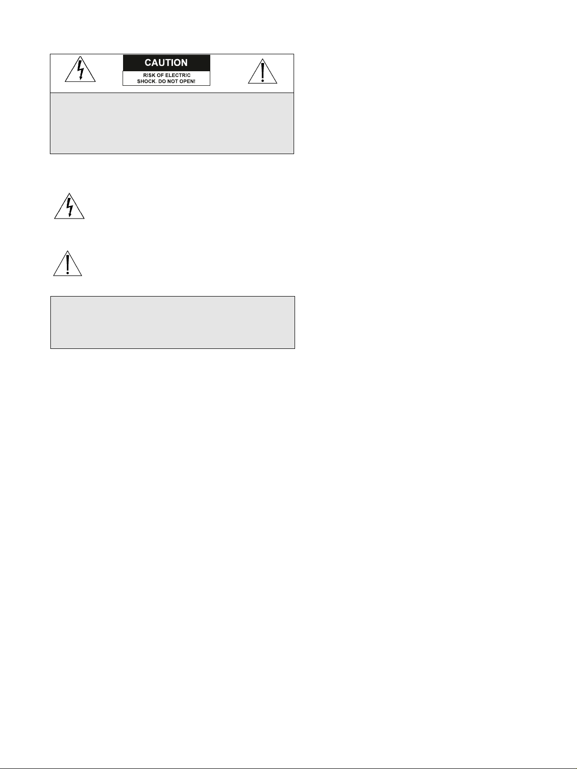
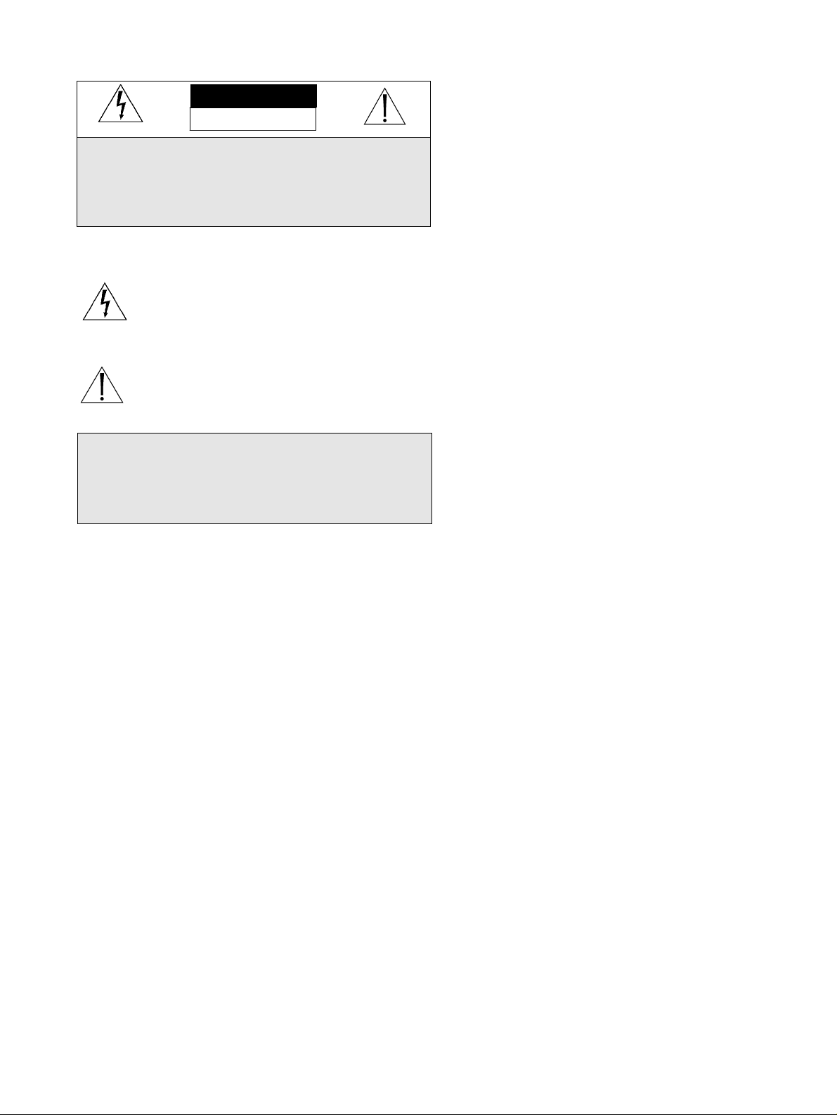
The lightning flash with an arrowhead symbol, within an
equilateral triangle, is intended to alert the user to the
presence of un-insulated "dangerous voltage" within the
product's enclosure that may be of sufficient magnitude to
constitute a risk of electric shock to persons.
The exclamation point within an equilateral triangle is
intended to alert the user to presence of important
operating and maintenance (servicing) instructions in the
literature accompanying the appliance.
CAUTION: TO REDUCE THE RISK OF ELECTRICAL
SHOCK, DO NOT OPEN COVERS. NO USER
SERVICEABLE PARTS INSIDE. REFER SERVICING TO
QUALIFIED SERVICE PERSONNEL.
WARNING
TO PREVENT FIRE OR SHOCK HAZARD, DO NOT
EXPOSE UNITS NOT SPECIFICALLY DESIGNED FOR
OUTDOOR USE TO RAIN OR MOISTURE.

1.4
1.5
CONTENTS
1 UNPACKING . . . . . . . . . . . . . . . . . . . . . . . . . .1.3
2 SERVICE . . . . . . . . . . . . . . . . . . . . . . . . . . . . . .1.3
3 CARE AND MAINTENANCE . . . . . . . . . . . . .1.3
4 DESCRIPTION . . . . . . . . . . . . . . . . . . . . . . . . .1.3
5 INSTALLATION . . . . . . . . . . . . . . . . . . . . . . . .1.4
5.1 Accessories . . . . . . . . . . . . . . . . . . . . . . . . . . . . .1.4
5.2 Disassembly . . . . . . . . . . . . . . . . . . . . . . . . . . . .1.4
5.3 Mounting the Unit . . . . . . . . . . . . . . . . . . . . . . .1.5
5.4 Camera/Lens Installation . . . . . . . . . . . . . . . . . . .1.6
5.5 Final Assembly . . . . . . . . . . . . . . . . . . . . . . . . . .1.7
1 UNPACKING
Unpack carefully. This is electro-mechanical equipment and
should be handled with care.
Check for the following items:
■ Model number of unit.
■ Hardware Kit.
(1) ¼-20 Button-Head Flange Screw
(1) Tamper-resistant Tool (basic models only)
(1) Alternate Camera Bracket
(1) Key (Locking models only)
If an item appears to have been damaged in shipment, replace it
properly in its carton and notify the shipper. If any items are
missing, notify your Philips Communication & Security
Systems Sales Representative or Customer Service.
The shipping carton is the safest container in which the unit
may be transported. Save it for possible future use.
2 SERVICE
If the unit ever needs repair service, the customer should contact
the nearest Philips Communication & Security Systems Service
Center for return authorization and shipping instructions.
3 CARE AND MAINTENANCE
There are no moving parts in this unit. Regularly scheduled
maintenance will help prolong the operation life of this unit.
Clean the viewing window as needed with a mild, non-abrasive
detergent in water and a soft cloth.
4 DESCRIPTION
The LTC 9405 series are wall or ceiling mounted security
housings designed for applications such as prisons, parking
garages and hospitals. These housings are ideal for any
application requiring secure CCTV monitoring.
LTC 9405 has an overall size of 279 mm x 165 mm x 140 mm
(11 in x 6.5 in x 5.5 in). The LTC 9405 series housings accept
camera-lens combinations up to 190 L x 68 W x 68 H mm (7.5
x 2.7 x 2.7 in).
For maximum protection and durability, the light weight cast
aluminum design of the LTC 9405 series housings provide the
strength equivalent 10 gage steel with the superior strength to
weight ratio of aluminum. The standard viewing window is
constructed of 9.5 mm (0.37 in.) clear polycarbonate treated
with a scratch-resistant coating. The removable cover provides
access to the camera and is secured with a single tamperresistant and captive screw. A special tool is provided for
turning the screw to open or close the cover. During servicing
or adjustment of the camera, the cover may be completely
removed or (if mounted on a ceiling) it may be left attached to
the top panel assembly using the "hinged slots" provided.
Attractively styled these housings are designed to be mounted
on the ceiling, on the wall horizontally or on the wall vertically.
Options include a key lock on the access panel and a clear
12.7 mm (0.5 in) viewing window.
5 INSTALLATION
This installation should be made by qualified service
personel and conform to the National Electrical Code
and applicable local codes.
Tools Required.
Allenwrench - 5/32-inch.
Wrench - 10 mm.
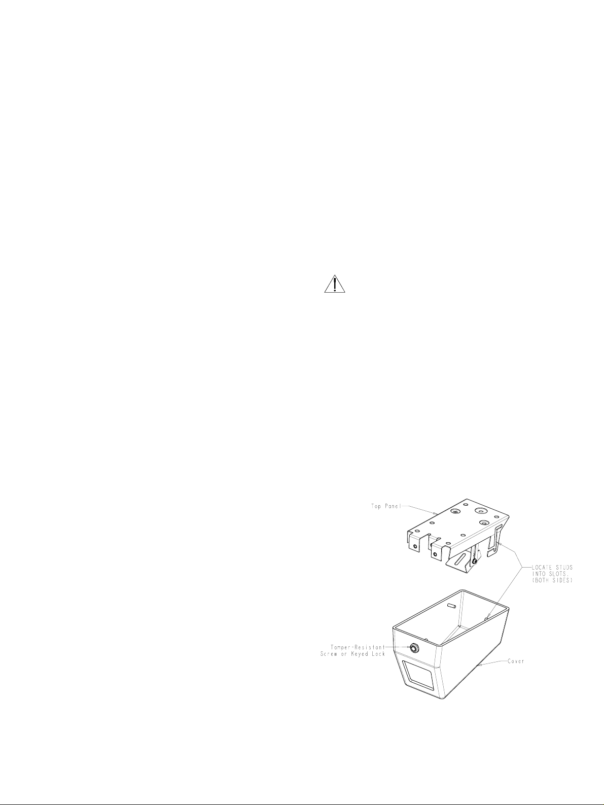
5.1 Disassembly
1. Remove the hardware kit from the shipping carton.
2. Models LTC 9405/00 and 9405/03 require the use of the
special tool to unscrew the tamper-resistant screw on the
front of the cover. See figure 1.
Models LTC 9405/01 and 9405/05 require the use of the
key to unscrew the lock on the front of the cover. See
figure 1.
Figure 1: Removing the cover
3. For all models, unscrew the screw or the lock until the front
of the cover is free from the top panel.
4. With the unit on a workbench or table, hold the cover
stationary. Remove the top panel by grasping it and pulling
it rearward, then upward for about 51 mm (2 in ), and
finally rearward again until the slots in the top panel have
cleared the studs in the cover.
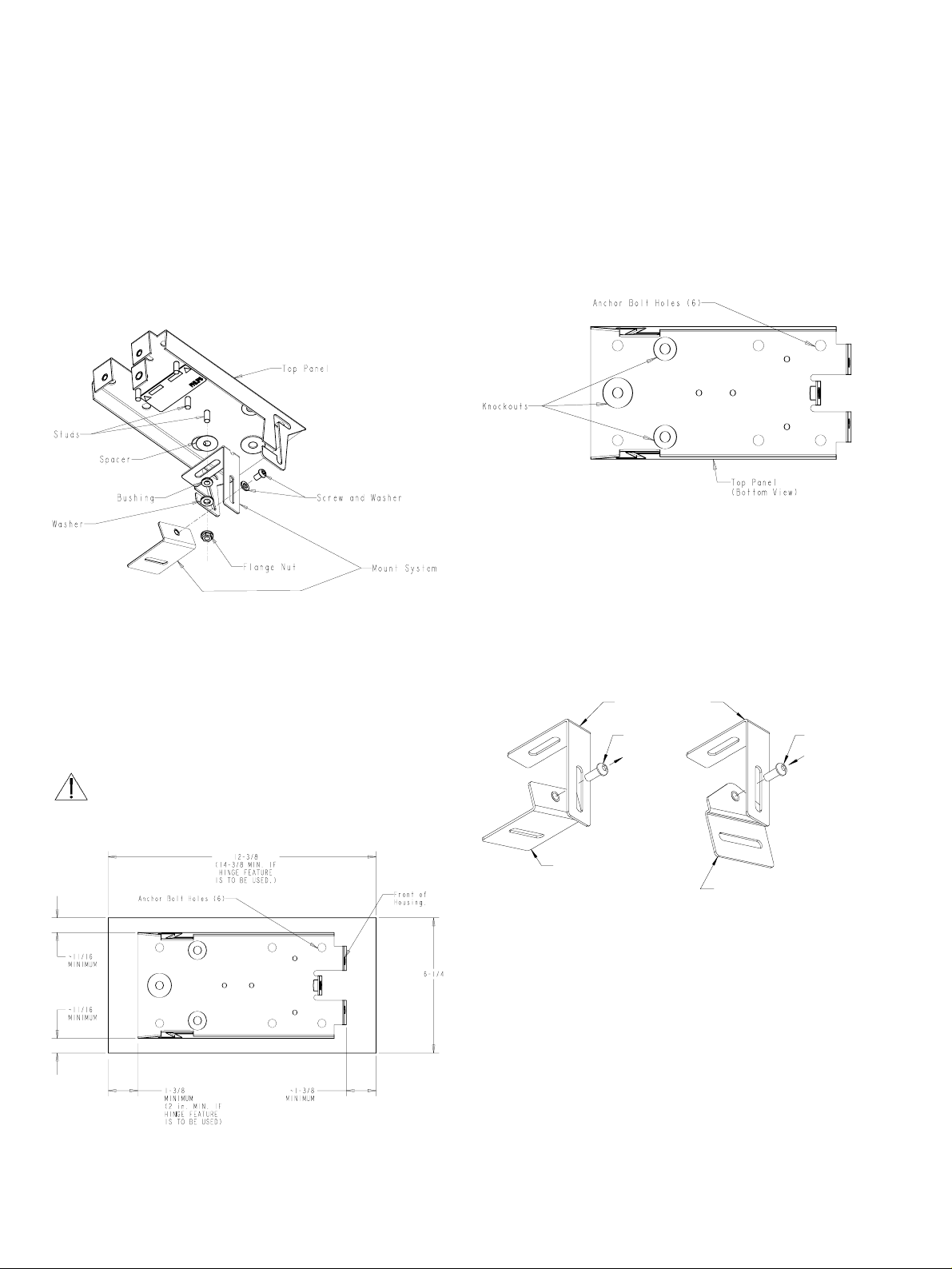
5. Unscrew the flange nut and remove the camera mount
system from the top panel. See figure 2. Do not lose the
parts, they will be needed to mount the camera and
reassemble the unit.
Figure 2: Removing the Mount System
5.2 Mounting the Unit
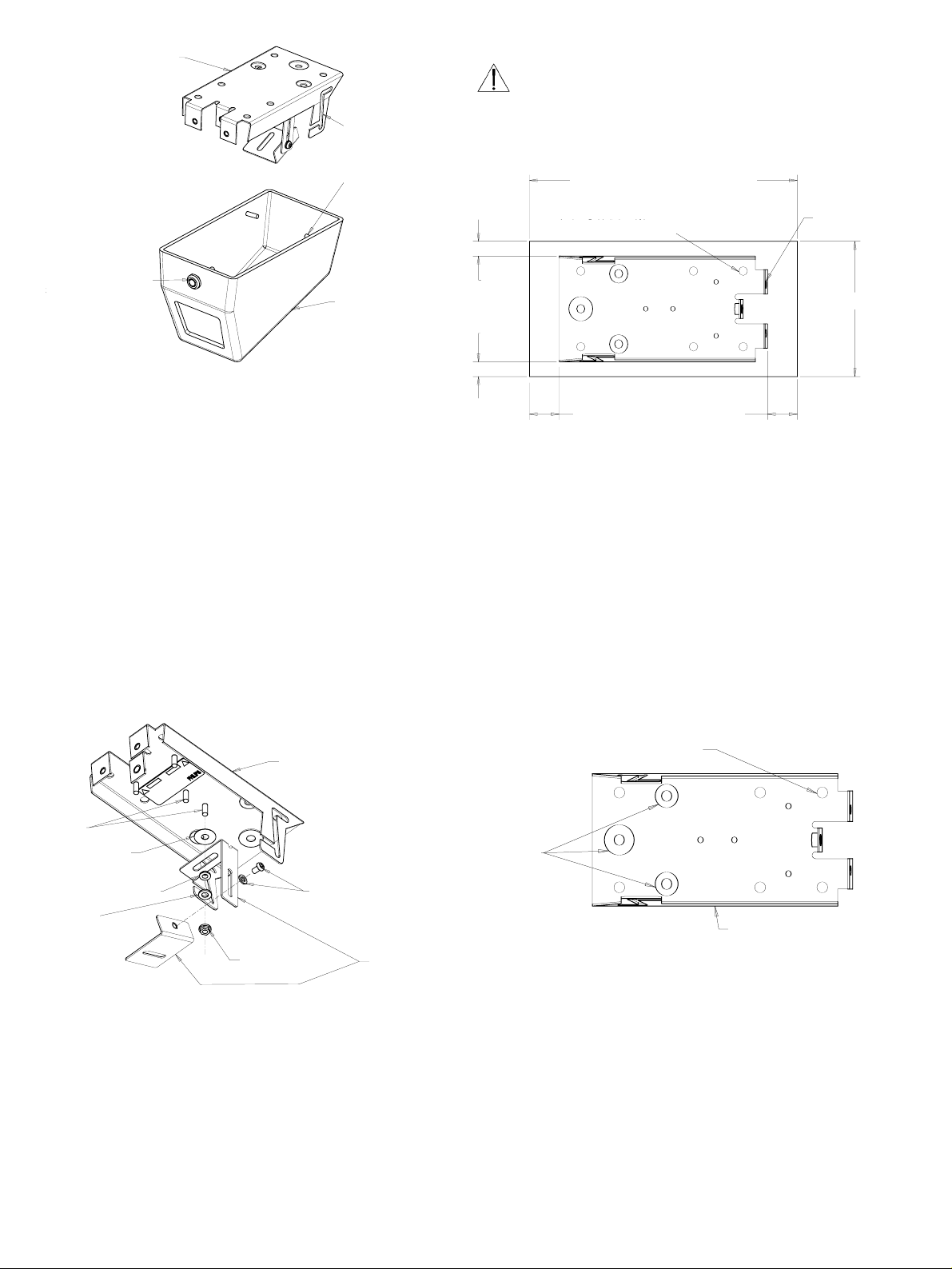
1. Position the top panel on the ceiling or wall, horizontally or
vertically, depending on the installation requirements. See
figure 3. A smooth flat surface is ideal for proper
installation. Note the minimum space requirements shown
in figure 3.
WARNING! - Do not use the hinge feature when the
unit is mounted on a wall. The cover may fall from
the top panel.
Figure 3: Positioning the Top Panel
2. Mark the anchor bolt locations on the mounting surface
using the holes in the top panel as a template. At least four
8-mm (5/16-in.) anchor bolts will be needed. Use of six
bolts is recommended.
3. Drill holes and install anchors as required by the type of
mounting surface.
4. Decide how the wiring will be routed to the unit. Two
knockouts for ½ inch conduit and one knockout for 3/4
inch conduit are provided. See figure 4.
Figure 4: Bolt Holes and Knockouts
5. Mount the top panel using the bolts and rout the wiring.
5.3 Camera/Lens Installation
1. If the installation requires that the camera be mounted
horizontally to a wall, remove the camera bracket from the
mounting system and install the alternate camera bracket
provided in the hardware kit. See figure 5.
Figure 5: Alternate Camera Mount
2. Reattach the camera mounting system to the top panel using
the same hardware that was removed in step 5 of section
5.1. Use either of the two studs near the center of the
panel, depending on the camera / lens size. See figures 6
and 7.
1.6
Mounting Bracket
Screw
Screw
Camera Bracket
Alternate
Camera Bracket
W9404408AE

Figure 6: Installing the Mount System
Figure 7: Securing the Mount System with Alternate Bracket
3. Secure the camera to the mount using the ¼-20 x ½ inch
button-head flange screw provided in the hardware kit. See
figures 8, 9 and 10.
Figure 8: Camera Mounts
Figure 9: Camera and Mount System
Figure 10: Camera Mounted with Alternate Bracket to a
Wall
5.4 Final Assembly
1. Mount the cover by aligning the two studs near the rear of
the cover with the openings of the z-shaped slots in the top
panel. Slide the cover to the rear, then upward and finally
to the rear again. Tighten tamper-resistant screw or lock
with key. See figure 11.
Figure 11: Installing the Cover
1.7
Button Head
Flange Screw
Camera
Camera
Button Head
Flange Screw
Alternate
Camera Bracket
W9404411AE
Camera
Bracket
2. Inspect the alignment of the camera / lens in the unit. The
camera / lens should be placed as close to the viewing
window as possible. Remove the cover and make
adjustments as needed and then replace the cover.
3. Secure the cover by turning either the tamper-resistant screw
(using the drive tool supplied) or the keyed lock (using the
key supplied) clockwise until the cover is in tight contact
with the top panel.
Note: Save the drive tool or the key for future use.
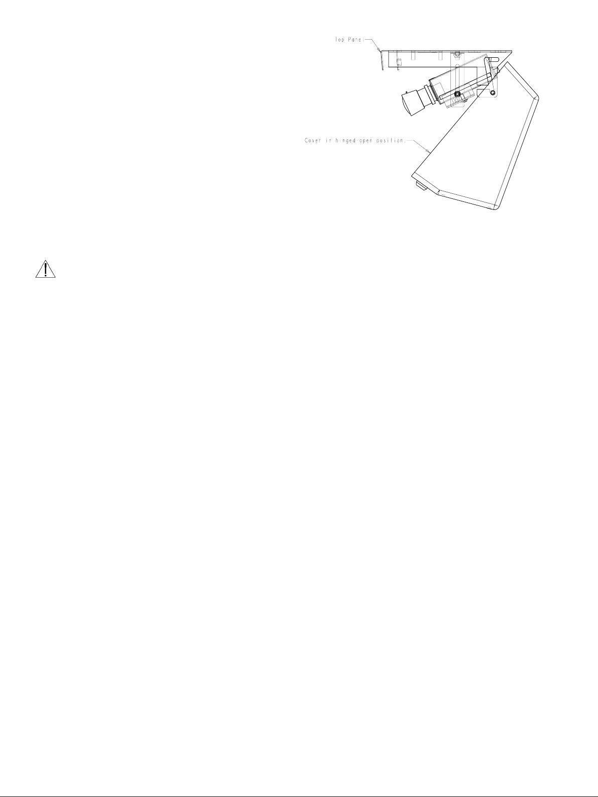
4. For installations where the unit is mounted to the ceiling,
the top cover may be hinged open for servicing or adjusting
the camera / lens. Simply allow the two studs in the rear of
the cover to rest in the bottom of the z-slots in the top
panel.
WARNING! - Do not use the hinge feature when the
unit is mounted to a wall, the cover may fall from the
top panel.
Figure 12: Cover Hinged Open
1.8
2.1
SECURITE
En raison de limitation de place, cette étiquette peut être placée sur le
dessous de l'appareil.
L'éclair fléché dans un triangle équilatéral, avertit
l'utilisateur de la présence d'une "tension dangereuse" non
isolée à l'intérieur de l'appareil et d'une valeur suffisante
pour constituer un risque d'électrocution.
Le point d'exclamation contenu dans un triangle
équilatéral, avertit l'utilisateur de la présence, dans la
documentation qui accompagne l'appareil, de consignes
d'utilisation et de maintenance importantes.
RISQUE DE CHOC ELECTRIQUE.
NE PAS OUVRIR.
ATTENTION
DANGER: POUR ÉVITER TOUT RISQUE
D'ÉLECTROCUTION, NE PAS OUVRIR LE BOÎTIER. IL
N'Y A PAS DE PIÈCES REMPLAÇABLES À
L'INTÉRIEUR. POUR TOUTE RÉVISION, S'ADRESSER
À UN TECHNICIEN SPÉCIALISÉ.
ATTENTION
POUR ÉVITER LE RISQUE D'ÉLECTROCUTION OU
D'INCENDIE, NE PAS EXPOSER À LA PLUIE OU À
L'HUMIDITÉ UN APPAREIL NON CONÇU POUR
UNE UTILISATION EXTÉRIEURE.

2.2

2.3
TABLE DES MATIERES
1 DEBALLAGE . . . . . . . . . . . . . . . . . . . . . . . . . . .2.3
2 MAINTENANCE . . . . . . . . . . . . . . . . . . . . . . .2.3
3 ENTRETIEN ET MAINTENANCE . . . . . . . . .2.3
4 DESCRIPTION . . . . . . . . . . . . . . . . . . . . . . . . .2.3
5 INSTALLATION . . . . . . . . . . . . . . . . . . . . . . . .2.3
5.1 Démontage . . . . . . . . . . . . . . . . . . . . . . . . . . . . .2.3
5.2 Montage de l'unité . . . . . . . . . . . . . . . . . . . . . . .2.4
5.3 Installation du bloc caméra/objectif . . . . . . . . . . .2.5
5.4 Montage final . . . . . . . . . . . . . . . . . . . . . . . . . . .2.6
1 DEBALLAGE
Déballez soigneusement le contenu de l'emballage. Il contient
un équipement électromécanique qui doit être manipulé avec
précaution.
Vérifiez que vous disposez des éléments suivants :
■ Le numéro de référence de l'unité.
■ Un kit matériel.
(1) Vis à tête demi-ronde ¼-20
(1) Outil de protection contre les effractions (modèles
de base uniquement)
(1) Applique de fixation amovible de la caméra
(1) Clé (modèles avec verrouillage uniquement)
Si l'un des éléments semble avoir été endommagé lors du
transport, remettez-le dans son carton d'emballage et avertissez
le transporteur. Si l'un des éléments manque, contactez votre
représentant ou votre service clientèle Philips Communication
& Security Systems.
Aucun container n'est mieux adapté que le carton d'emballage
pour transporter l'unité. Nous vous conseillons donc de le
conserver. Vous pourriez en avoir besoin ultérieurement.
2 MAINTENANCE
Veuillez contacter le service de maintenance Philips
Communication & Security Systems le plus proche de votre
domicile pour assurer la maintenance ou la réparation de l'unité.
Vous obtiendrez une autorisation et toutes les informations
utiles sur le renvoi du produit.
3 ENTRETIEN ET MAINTENANCE
Cette unité n'intègre aucune pièce détachée. Une maintenance
régulière permet d'en prolonger la durée de vie. Nettoyez la
fenêtre au moyen d'un chiffon doux et d'un produit d'entretien
non abrasif dilué dans de l'eau.
4 DESCRIPTION
Les boîtiers de protection LTC 9405 pour montage mural ou
sur plafond ont été notamment conçus pour assurer la
surveillance des prisons, des parkings ou des garages et des
hôpitaux. Cependant, ils s'adaptent parfaitement à toutes les
applications nécessitant la mise en place d'un système de
vidéosurveillance en circuit fermé.
D'un encombrement réduit de 279 x 165 x 140 mm, les
LTC 9405 prennent en charge des blocs caméra/objectif aux
dimensions maximales suivantes : 190 (l) x 68 (d) x 68 (h) mm.
Grâce à leur conception ultra-légère en aluminium fondu, les
boîtiers LTC 9405 sont d'une résistance équivalente à un acier
de calibre 10 supérieure au ratio pondéré de l'aluminium et
bénéficient ainsi d'une protection et d'une solidité optimales. La
fenêtre de visualisation standard est conçue en polycarbonate
transparent de 9,5 mm et recouvert d'une couche anti-abrasive.
Le capot amovible, fixé au moyen d'une seule vis captive antieffraction, permet d'accéder à la caméra. Un outil spécial
(fourni) permet de l'ouvrir ou de le fermer en vissant ou
dévissant la vis. Lors de l'entretien ou du réglage de la caméra, il
est nécessaire de retirer complètement le capot. Dans le cadre
d'un montage sur plafond, cependant, il doit rester attaché au
panneau de montage supérieur au moyen des pitons de fixation.
Ces boîtiers attrayants sont conçus pour un montage mural, à
l'horizontale ou à la verticale, et sur plafond. Vous disposez en
option d'un verrou situé sur le panneau d'accès et d'une fenêtre
de visualisation transparente de 12,7 mm.
5 INSTALLATION
Seul un technicien qualifié est habilité à installer cette
unité, conformément aux normes électriques en vigueur
dans votre pays.
Outils requis :
Clé à vis 5/32".
Clé à vis 10 mm.
5.1 Démontage
1. Retirez le kit matériel du carton d'emballage.
2. Pour retirer la vis anti-effraction située sur le panneau avant
du capot des modèles LTC 9405/00 et 9405/03, vous devez
utiliser l'outil spécial correspondant. Veuillez vous référer à
la figure 1.
Pour ouvrir le verrou situé sur le panneau avant du capot des
modèles LTC 9405/01 et 9405/05, vous devez utiliser la clé
correspondante. Veuillez vous référer à la figure 1.
2.4
Figure 1 : Retrait du capot
3. Quel que soit le modèle, retirez la vis ou ouvrez le verrou
afin de dégager le panneau avant du capot du panneau
supérieur.
4. Placez l'unité sur un plan de travail ou une table et
immobilisez le capot. Retirez le panneau supérieur en le
tenant fermement et en le tirant vers l'arrière, en le soulevant
vers le haut sur environ 51 mm, puis en le tirant de nouveau
vers l'arrière jusqu'à ce que les supports de fixation soient
totalement dégagés des pitons correspondant situés sur le
capot.
5. Dévissez l'écrou, puis retirez le support de montage de la
caméra du panneau supérieur. Veuillez vous référer à la
figure 2. Ne perdez aucun éléments, vous en aurez besoin
pour remettre la caméra en place et remonter l'unité.
Figure 2 : Retrait du système de montage
5.2 Montage de l'unité
1. Placez le panneau supérieur sur le plafond ou le mur, à
l'horizontale ou à la verticale, en fonction des exigences
requises par votre installation (figure 3). Pour que celle-ci
soit correcte, choisissez de préférence une surface plane et
lisse. Veuillez noter l'espace minimum requis en vous
référant à la figure 3.
AVERTISSEMENT - N'utilisez pas le système de
supports de fixation en forme de Z/pitons lorsque
vous montez l'unité sur un mur. En effet, le capot
pourrait se détacher du panneau supérieur.
Figure 3 : Installation du panneau supérieur
2. Marquez l'emplacement des boulons sur la surface de
montage au moyen des orifices situés sur le panneau
supérieur. Vous devez utiliser au moins quatre boulons de 8
mm. Nous vous recommandons cependant d'en utiliser six.
3. Percez les trous et installez les chevilles appropriées à la
surface de montage.
4. Déterminez l'acheminement des câbles jusqu'à l'unité. Cette
dernière intègre deux parois amovibles permettant le passage
d'un câble d'1/2" et une paroi amovible de 3/4". Veuillez
vous référer à la figure 4.
Figure 4 : Orifices pour boulons et parois amovibles
5. Fixez le panneau supérieur au moyen des boulons et
acheminez les câbles.
Panneau supérieur
Insérez les pitons
(situés de chaque côté)
dans les supports de
fixation en forme de Z
Vis anti-effraction ou
verrou
Capot
Panneau supérieur
Boulons
Bague
d'insertion
Bague de réduction
Rondelle
Vis et rondelle
Ecrou
Support de
montage
12-3/8 (14-3/8 min)
Si le système de supports de fixation en
forme de Z/pitons est utilisé
Panneau
avant du
boîtier
Orifices de fixation des boulons avec cheville (6)
Panneau supérieur (vue de
dessous)
Parois
amovibles
Orifices de fixation des boulons
avec cheville (6)
1-3/8 minimum
(2 in min. Si le
système de supports
de fixation en forme
de Z/pitons est
utilisé
-11/16
minimum
-11/16
minimum
-1-3/8
minimum
6-1/4
 Loading...