

Philips LTC 3963-51 User Manual

Time-lapse
Video Recorder
Eng
D
F
I
E
Instructions for Use
NL
LTC 3963/51

ENGLISH
IMPORT ANT SAFEGUARDS
1. Read Instructions — All the safety and operating instructions
should be read before the unit is operated.
2. Retain Instructions — The safety and operating instructions
should be retained for future reference.
3. Heed Warnings — All warnings on the unit and in the operating
instructions should be adhered to.
4. Follow Instructions — All operating and use instructions should
be followed.
5. Cleaning — Unplug the unit from the outlet before cleaning. Do
not use liquid cleaners or aerosol cleaners. Use a damp cloth for
cleaning.
6. Attachments — Do not use attachments not recommended by the
product manufacturer as they may cause hazards.
7. Water and Moisture — Do not use this unit near water – for
example, near a bath tub, wash bowl, kitchen sink, or laundry tub,
in a wet basement, near a swimming pool, in an unprotected outdoor installation, or any area which is classified as a wet location.
8. Accessories — Do not place this unit on an unstable stand, tripod,
bracket, or mount. The unit may fall, causing serious injury to a
person and serious damage to the unit. Use only with a stand, tripod, bracket, or mount recommended by the manufacturer, or
sold with the product. Any mounting of the unit should follow the
manufacturer’s instructions, and should use a mounting accessory recommended by the manufacturer.
An appliance and cart combination should be
moved with care. Quick stops, excessive force, and
uneven surfaces may cause the appliance and cart
combination to overturn.
9. Ventilation — Openings in the enclosure, if any, are provided for
ventilation and to ensure reliable operation of the unit and to protect it from overheating. These openings must not be blocked or
covered. This unit should not be placed in a built-in installation
unless proper ventilation is provided or the manufacturer’s
instructions have been adhered to.
10. Power Sources — This unit should be operated only from the type
of power source indicated on the marking label. If you are not
sure of the type of power supply you plan to use, consult your
appliance dealer or local power company. For units intended to
operate from battery power, or other sources, refer to the
operating instructions.
11. Grounding or Polarization — This unit may be equipped with a
polarized alternating-current line plug (a plug having one blade
wider than the other). This plug will fit into the power outlet only
one way. This is a safety feature. If you are unable to insert the
plug fully into the outlet, try reversing the plug. If the plug should
still fail to fit, contact your electrician to replace your obsolete
outlet. Do not defeat the safety purpose of the polarized plug.
Alternately, this unit may be equipped with a 3-wire groundingtype plug, a plug having a third (grounding) pin. This plug will
only fit into a grounding-type power outlet. This is a safety feature. If you are unable to insert the plug into the outlet, contact
your electrician to replace your obsolete outlet. Do not defeat the
safety purpose of the grounding-type plug.
12. Power-Cord Protection — Power-supply cords should be routed
so that they are not likely to be walked on or pinched by items
placed upon or against them, paying particular attention to cords
and plugs, convenience receptacles, and the point where they exit
from the appliance.
13. Power Lines — An outdoor system should not be located in the
vicinity of overhead power lines or other electric light or power
circuits, or where it can fall into such power lines or circuits.
When installing an outdoor system, extreme care should be taken
to keep from touching such power lines or circuits as contact with
them might be fatal. U.S.A. models only – refer to the National
Electrical Code Article 820 regarding installation of CATV
systems.
14. Overloading — Do not overload outlets and extension cords as
this can result in a risk of fire or electric shock.
15. Object and Liquid Entry — Never push objects of any kind into
this unit through openings as they may touch dangerous voltage
points or short-out parts that could result in a fire or electric
shock. Never spill liquid of any kind on the unit.
16. Servicing — Do not attempt to service this unit yourself as opening or removing covers may expose you to dangerous voltage or
other hazards. Refer all servicing to qualified service personnel.
17. Damage Requiring Service — Unplug the unit from the outlet and
refer servicing to qualified service personnel under the following
conditions.
a. When the power-supply cord or plug is damaged.
b. If liquid has been spilled, or objects have fallen into the unit.
c. If the unit has been exposed to rain or water.
d. If the unit does not operate normally by following the operating
instructions. Adjust only those controls that are covered by the
operating instructions, as an improper adjustment of other
controls may result in damage and will often require extensive
work by a qualified technician to restore the unit to its normal
operation.
e. If the unit has been dropped or the cabinet has been damaged.
f. When the unit exhibits a distinct change in performance – this
indicates a need for service.
18. Replacement Parts — When replacement parts are required, be
sure the service technician has used replacement parts specified
by the manufacturer or have the same characteristics as the original part. Unauthorized substitutions may result in fire, electric
shock or other hazards.
19. Safety Check — Upon completion of any service or repairs to this
unit, ask the service technician to perform safety checks to determine that the unit is in proper operating condition.
20. Coax Grounding — If an outside cable system is connected to the
unit, be sure the cable system is grounded. U.S.A. models only –
Section 810 of the National Electrical Code, ANSI/NFPA No. 701981, provides information with respect to proper grounding of
the mount and supporting structure, grounding of the coax to a
discharge unit, size of grounding conductors, location of
discharge unit, connection to grounding electrodes, and
requirements for the grounding electrode.
21. Lightning — For added protection of this unit during a lightning
storm, or when it is left unattended and unused for long periods
of time, unplug it from the wall outlet and disconnect the cable
system. This will prevent damage to the unit due to lightning and
power-line surges.
As the colours of the wires in the mains lead of
this apparatus may not correspond with the
coloured markings identifying the terminals in
your plug, proceed as follows:
– the wire which is coloured green and yellow
must be connected to the terminal in the
plug which is marked with the letter E or by
the earth symbol , or coloured green
or green and yellow.
– the wire which is coloured blue must be
connected to the terminal which is marked
with the letter N or coloured black.
– the wire which is coloured brown must be
connected to the terminal which is marked
with the letter L or coloured red.
WARNING — THIS APPARATUS MUST BE
EARTHED.
1
SAFETY PRECAUTIONS
RISK OF ELECTRIC
SHOCK. DO NOT OPEN!
CAUTION
CAUTION: TO REDUCE THE RISK OF ELECTRIC SHOCK,
DO NOT OPEN COVERS. NO USER SERVICEABLE PARTS
INSIDE. REFER SERVICING TO QUALIFIED SERVICE
PERSONNEL.
This label may appear on the bottom of the unit due
to space limitations.
The lightning flash with an arrowhead symbol, within an equilateral triangle, is intended
to alert the user to the presence of uninsulated “dangerous voltage” within the product’s enclosure that may be of sufficient
magnitude to constitute a risk of electric
shock to persons.
The exclamation point within an equilateral
triangle is intended to alert the user to presence of important operating and maintenance (servicing) instructions in the literature
accompanying the appliance.
WARNING
To prevent fire or shock hazard, do not expose
units not specifically designed for outdoor use
to rain or moisture.
Attention: Installation should be performed
by qualified service personnel only in accordance with the National Electrical Code or
applicable local codes.
Power Disconnect: Units with or without
ON-OFF switches have power supplied to the
unit whenever the power cord is inserted
into the power source; however, the unit is
operational only when the ON-OFF switch is
in the ON position. The power cord is the
main power disconnect for all units.
External Power Supplies
Use Only the Recommended Power Supplies.
Power supplies must comply with the
requirements of the latest version of IEC
65/VDE 0860. Substitutions may damage the
unit or cause a fire or shock hazard.
ATTENTION
OBSERVE PRECAUTIONS
FOR HANDLING
ELECTROSTATIC
SENSITIVE
DEVICES
WARNING: Electrostatic-sensitive device. Use
proper CMOS/MOSFET handling precautions to
avoid electrostatic discharge.
NOTE: Grounded wrist straps must be worn and
proper ESD safety precautions observed when
handling the electrostatic-sensitive printed circuit
boards.
1 UNPACKING
Unpack carefully. This is electronic equipment and
should be handled carefully.
Check to ensure that the following items are included:
• Model number of unit.
If an item appears to have been damaged in shipment, replace it properly in its carton and notify the
shipper. If any items are missing, notify your Philips
Communication & Security Systems Inc. Sales
Representative or Customer Service.
The shipping carton is the safest container in which
the unit may be transported. Save it for possible
future use.
2 SERVICE
If the unit ever needs repair service, the customer
should contact the nearest Philips Communication
& Security Systems Inc. Service Center for return
authorization and shipping instructions.
Service Centers
U.S.A. & Canada: 800-366-2283
Mexico & Central America: 52-5-564-2726
Europe & Middle East: 44-1932-765666
South America: 54-1-956-0837
Australia: 61-2-888-9000
New Zealand: 64-4-237-7297
220-240 V, 50 Hz Power Cords
220-240 V, 50 Hz power cords, input and output, must comply with the latest versions of
IEC Publication 227 or IEC Publication 245.
3 DESCRIPTION
4 INSTALLATION
2
FEATURES CONTENTS
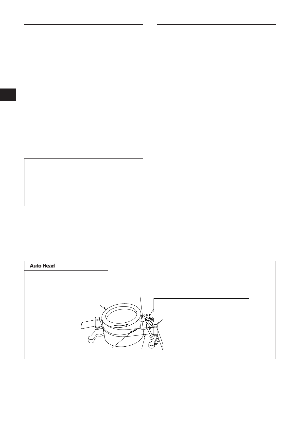
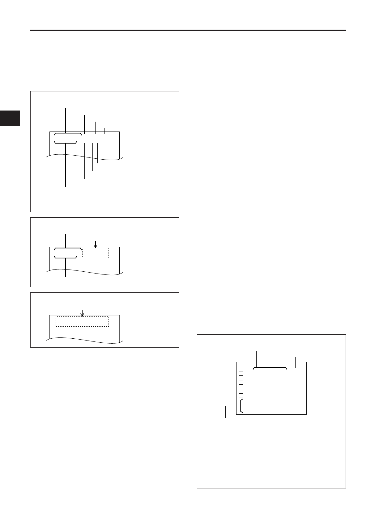
Touches the video head in the active position
Cylinder
Cleaning roller in the stand-by position
(Special material)
Tape guide
Tape
Video head
Recording
• HD (High Density) Mode Recording Only
• Eight Touch-Selectable Recording Speeds
• Automatic “Alarm-Command” Speed Up
• Recording Check
• One Shot Recording
• On-Screen and On-Tape Time/Date Information
• 7-Day Programmable On/Off Timer
• “Alarm On” Output
• Usable Audio at 09 and 27 Hour Speeds
• RS-232C Interface Connector
Playback
• Time-of-Alarm Memory and Alarm Index Search
• High Speed Visual Search
• Seven Playback Speeds
• Still Field, Field-Advance, Field-Reverse and
Reverse Playback
Security
• About 720 Hours Memory Protection
• Electronic Security Lockout
Note: This recorder has a rechargeable battery
to maintain display functions and recording
mode within 720 hours in the event of power
loss. When the recorder is received, the unit
must be connected to power source for 48
hours to assure the battery has been adequately charged.
IMPORTANT SAFEGUARDS......................................1
SAFETY PRECAUTIONS.............................................2
PRECAUTIONS............................................................4
CONTROLS AND FUNCTIONS ..................................5
INSTALLATION ...........................................................9
EXTERNAL CONNECTIONS.....................................10
CASSETTE TAPES ....................................................12
SETUP........................................................................13
SETTING THE TIME AND DATE..........................14
SETTING [OPTIONS] ITEMS................................15
SUMMER TIME FUNCTION.................................15
SETTING THE TIMER ...........................................15
SETTING THE VCR FUNCTIONS.........................17
SETTING THE BUZZER.........................................18
SETTING THE ALARM..........................................19
ALARM MEMORY RECALL AND RESET ............20
OPERATION...............................................................21
TAPE RECORDING................................................21
REC CHECK............................................................21
AUTO REC CHECK................................................21
ONE SHOT RECORDING......................................21
TIMER RECORDING..............................................21
TAPE RECYCLE .....................................................21
ALARM RECORDING............................................22
MASTER SYSTEM RESET....................................22
PLAYBACK.............................................................22
STILL PLAYBACK..................................................22
V.LOCK ADJUST...................................................22
PLAYBACK IN THE FIELD ADVANCE/
REVERSE MODES ............................................23
VISUAL SEARCH (High Speed Scan) .................23
ALARM INDEX SEARCH ......................................23
TO SECURE THE VCR ..........................................23
OPERATING THE VCR FROM A PERSONAL
COMPUTER...........................................................24
PROBLEM GUIDE......................................................28
SPECIFICATIONS ......................................................29
Auto Head Cleaning System
This system cleans the video heads automatically when a cassette is inserted and ejected or the tape is
rewound in the recycle recording mode, to prevent dirt from accumulating on the heads.
3

PRECAUTIONS
Safety
• Should any solid object or liquid fall into the cabinet, turn off the unit and have it checked by qualified personnel before operating it any further.
• To disconnect the mains lead, pull it out by the
plug. Never pull the lead itself.
Installation
• Choose a location in which air can pass through
the ventilation holes in the bottom, top and back
of the unit to prevent it from overheating.
• Do not install the unit near heat sources such as
radiators or air ducts or in a place subject to direct
sunlight, excessive dust, mechanical vibrations or
shock.
• Do not place heavy objects or heat-generating
objects on the VCR, or the cabinet could be damaged or the temperature inside the VCR could
rise, which could cause a fault.
• Never bring a magnet or magnetized object near
the VCR because it will adversely affect the performance of the VCR.
• Do not install the unit in an inclined position.
The unit is designed for operation in a horizontal
position.
Operation
• Condensation
If you pour a cold liquid into a glass, water vapor
in the air will condense on the surface of the
glass.
This is the condensation of moisture.
Condensation on the head drum, one of the most
crucial parts of the VCR, will cause damage to the
tape. The VCR should not be operated for at least
2 hours after being moved from a cold to a hot
environment to avoid condensation from occurring on the head drum.
Cleaning
• Be careful; when the surface of the case is wiped
with a volatile agent such as benzine, alcohol,
thinner, etc., or a chemically processed cloth, the
surface finish may be degraded or its coating may
peel off.
Repacking
• It is wise to save the packing materials and box in
case you ever need to ship or store your unit.
4

[FRONT]
1
3
2
4 5 6 7 8 9 10 11 12 13 14 15 16 18 1917
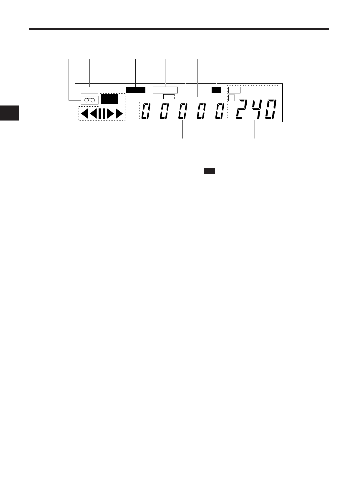
DISPLAY (See page 7)
S
CONTROLS AND FUNCTIONS
1. RESET BUTTONS
Press these buttons at the same time to clear all
(microprocessor) functions.
Press the “S” button to reset the system. (This does
not erase the stored information.)
2. CASSETTE COMPARTMENT
3. SHARPNESS CONTROL
Adjust the picture quality to hard or soft during playback.
4. TRACKING CONTROL
Adjust to optimize the picture quality during playback
at the 09 and 27 hour speeds.
5. SLOW TRACKING CONTROL
Adjust to optimize the picture quality in the SLOW
PLAY mode, e.g. speeds over 48 hours.
6. V. LOCK CONTROL
Reduces vertical jitter in the still play mode.
7. PROGRAM BUTTON
Press to select one of the six programmable functions.
8. START/STOP BUTTON
Press to start or stop the programming of a programmable function. (Press once to start the programming
sequence and a second time to stop (end) it.)
11. UP BUTTON
Press to increase, change or advance to the next
higher value.
12. V-POS (VERTICAL POSITION) BUTTON
Press repeatedly to control the vertical position of the
programmable display on the monitor.
13. H-POS (HORIZONTAL POSITION) BUTTON
Press repeatedly to control the horizontal position of
the programmable display on the monitor.
14. ALARM INDEX BUTTON
Press this button to cause the INDEX indicator to light,
and set the VCR to the visual search mode (press
F.FWD or REWIND during playback mode) in this
state; the start of the alarm recorded can be located.
15. ALARM RESET BUTTON
Press to clear POWER LOSS information. When this
button is pressed, the alarm memory is cleared.
16. COUNTER RESET BUTTON
Press to clear the digital counter to “00000”.
17. REC/PLAY HOURS BUTTONS
▲ (UP): Press to increase hours to the next
higher value.
▼ (DOWN): Press to decrease hours to the next
lower value. The tape speed will be
indicated as part of the monitor display.
9. SET BUTTON
10. DOWN BUTTON
5
Press to select the specific value which is to be
changed with the UP/DOWN buttons.
Press to decrement, change or reverse to the
previous/lower value.
18. TIMER BUTTON
Press after programming the TIMER for automatic
TIMER recording. See page 15 for TIMER programming.
19. SUMMER TIME BUTTON
Press to set the summer time. See “SUMMER TIME
FUNCTION” on page 15 for details.

20
21 222423
25 26
29
28
27
20. EJECT BUTTON
Press to remove the cassette. The EJECT button will
not operate in the RECORD mode.
21. FIELD REVERSE BUTTON
Press to reverse the tape by one field in the STILL
playback mode.
22. STILL BUTTON
Press to momentarily stop tape motion in the play
mode. The STILL function allows close inspection of
individual scenes. See the description of STILL playback on page 22.
23. FIELD ADVANCE BUTTON
Press to advance the tape one field in the STILL playback mode.
24. RECORD BUTTON
Press to start recording.
25. STOP BUTTON
Press to stop the tape. The STOP button must be
pressed to end the RECORD and PLAY mode.
26. PLAY BUTTON
Press to play recorded material in the forward direction. Pressing this during recording makes it possible
to check recordings.
27. REVERSE PLAY BUTTON
Press to play recorded material at the 09, 72, 120,
168, 240 speed in the reverse direction during the
PLAY mode.
28. FAST FORWARD/VISUAL SEARCH BUTTON
Press to activate fast forward.
Press this button during playback and a forward playback picture at high speed can be seen.
29. REWIND/VISUAL SEARCH BUTTON
Press to start rewind.
Press this button during playback and a reverse playback picture at high speed can be seen.
6
CONTROLS AND FUNCTIONS (Continued)
[DISPLAY]
30
31 32 33 34 3635
TAB
REC
ALARM
INDEX
37 39 4038
30. TAPE-IN INDICATOR
Lights when a cassette is in the compartment.
31. TAB INDICATOR
Lights when a cassette without its safety tab is loaded.
32. ALARM INDICATOR
ALARM appears during alarm recording.
ALARM flashes when alarm recording ends.
33. TAPE END INDICATOR
Lights when the tape reaches the end during recording.
Note: “TAPE END” is not displayed when you have
selected REWIND, RE-REC in the “RECYCLE FUNCTIONS” menu in the alarm display or you have
selected REWIND, STOP IF ALARM but an alarm
recording has not been made.
34. A INDICATOR
Lights when no video signal is input. Video signal
input will turn this indicator off automatically.
35. TIMER INDICATOR
This is lit during timer recording or TIMER stand-by
mode.
The indicator flashes in the following cases.
• A cassette is not loaded.
• A cassette without its safety tab is loaded.
• The timer has not been programmed.
TAPE END
TIMER
A
LOCK
SPEED
HD
37. VCR MODE INDICATORS
• appears during recording.
REC
• tt appears during the rewind mode.
• ss appears during the fast forward mode.
• tt (or ss) flashes during visual search.
• s appears during the playback mode.
• t appears during the reverse play mode.
❙❙
•
• t
appears when the STILL button is pressed
during play mode and disappears when the
STILL or PLAY button is pressed again.
❙❙
(or ❙❙s) appears while the FIELD REV (or
FIELD ADV) is held depressed in the still
playback mode.
Note: Still playback is restored when the
FIELD REV (or FIELD ADV) button is
released.
38. INDEX INDICATOR
INDEX appears when the ALARM INDEX button is
pressed.
INDEX disappears when the ALARM INDEX button is
pressed again.
INDEX flashes during alarm indexing.
39. DIGITAL COUNTER
Shows the tape counter. The counter does not count
during non-recorded sections of a tape.
40. TAPE SPEED INDICATOR
Shows the tape speed.
36. LOCK INDICATOR
LOCK appears when the recorder is in the security
lock mode.
7
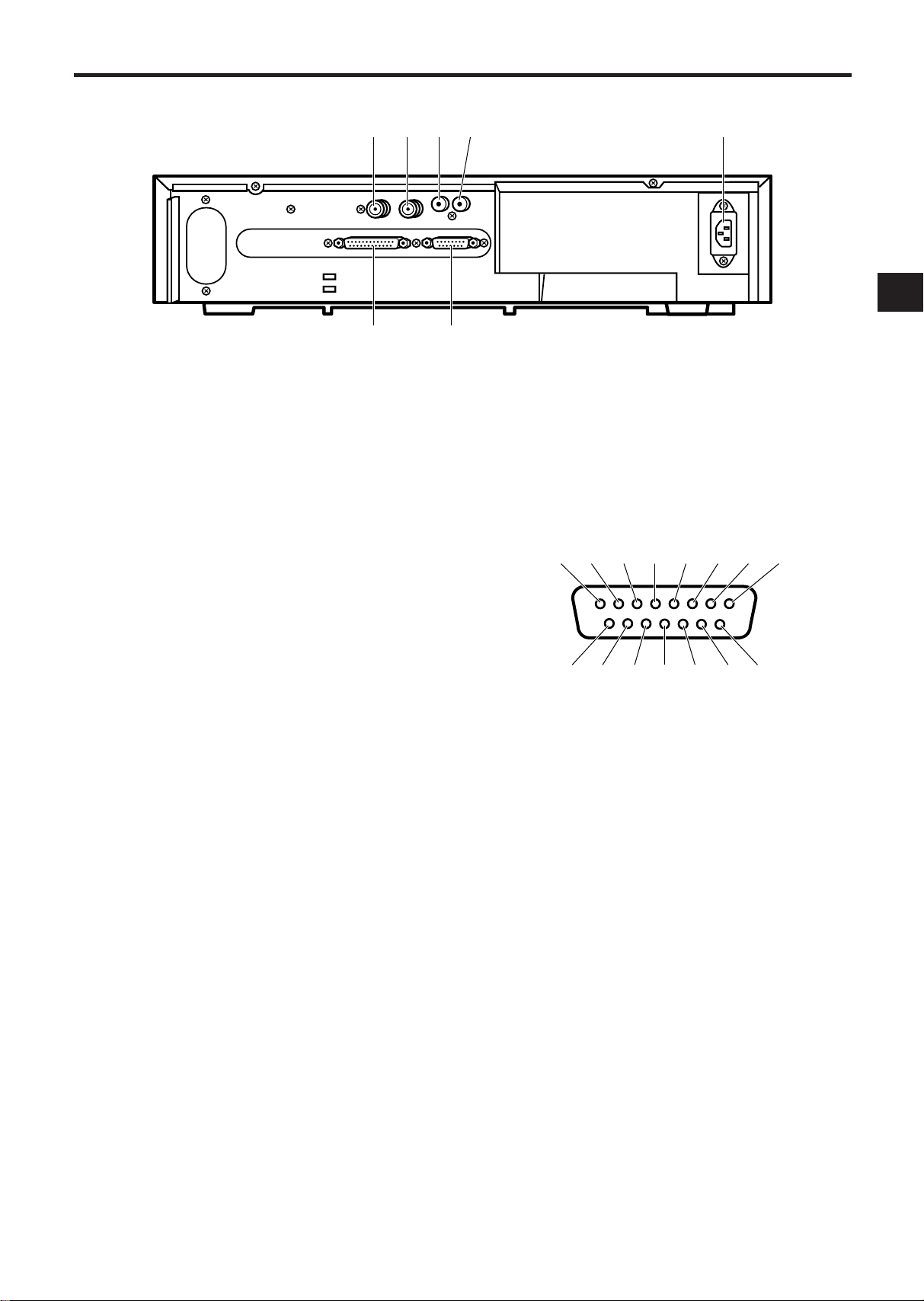
[REAR]
trewqyui
!2 !1 !0 o!3!4!5
41
42 43 4544
46
41. VIDEO IN
Receives video signal from a video camera or another
VCR.
42. VIDEO OUT
For connection to monitor.
43. AUDIO IN
Accepts an audio signal from a camera, external
sound equipment or another recorder (Line: –8 dBm,
50 Kohm, unbalanced).
44. AUDIO OUT
Provides an audio output for a monitor or another
recorder (–9 dBm, 600 ohm, unbalanced).
45. AC INLET
46. RS-232C INTERFACE (D-SUB25) JACK
Used to operate this VCR from a personal computer
on control system.
47
47. EXTERNAL INTERFACE (15-PIN) JACK
Connect an alarm switch, door sensor, etc. using the
15-pin adapter provided.
q ALARM (A) IN
w ALARM OUT
e ONE SHOT IN
r TAPE END OUT
t TAPE END RESET
y WARNING OUT
u ALARM B IN
i TIME ADJUST
o CAMERA SW OUT
!0 REC START IN
!1 REC OUT
!2 LOW TAPE OUT
!3 REMOTE IN
!4 REC CHECK IN
!5 GND
8
INSTALLA TION
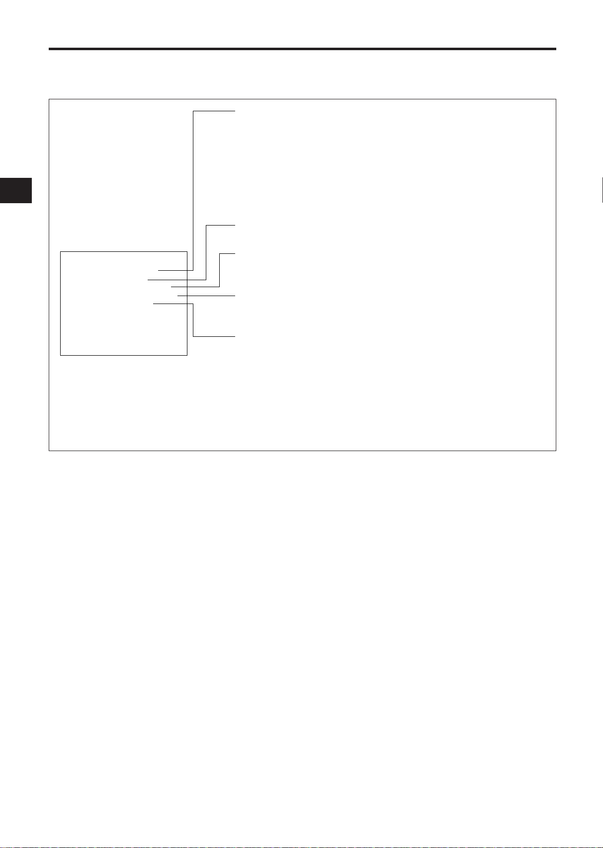
VIDEO CONNECTIONS
Use coaxial cables when connecting a camera and a
monitor to this VCR.
Note: Long cable runs to distant cameras may
cause signal deterioration and/or sync discrepancies. If these problems occur, use video line
amplifiers and/or cameras having phase-adjustable
line-locked vertical sync.
Video Input
In single camera systems, connect the camera to the
Video IN BNC terminal on the VCR rear panel. Use
of a 2:1 interlace camera is highly recommended;
otherwise, the monitor will show vertical distortion
of the TIME/DATE characters.
In multiple camera systems, connect the switcher
output to the Video IN BNC terminal. Because multiple camera systems require synchronization, use
of cameras having line-locked vertical sync or a genlocked master drive/sync source is highly recommended. The use of vertical interval switchers
is also recommended.
Video Output
Connect the monitor to the Video OUT BNC terminal
on the rear panel.
AUDIO CONNECTIONS
Note: Audio recording can be performed at the 09
and 27-hour recording speeds and audio playback at
the 09 and 27 speeds.
Audio In:
Accepts an audio signal from a camera,
external sound equipment, or another recorder
(Line: –8 dBm, 50 kohm).
Audio Out:
Provides an audio output for a monitor
or another recorder (–9 dBm, 600 ohm, unbalanced).
USING THE 15-PIN ADAPTER
Attach the wires of the alarm switch, door sensor or warning lamp to the 15-pin adapter
using screws.
After connection, connect the adapter to the
EXTERNAL INTERFACE jack on the rear of the
VCR.
See pages 10 and 11 for details.
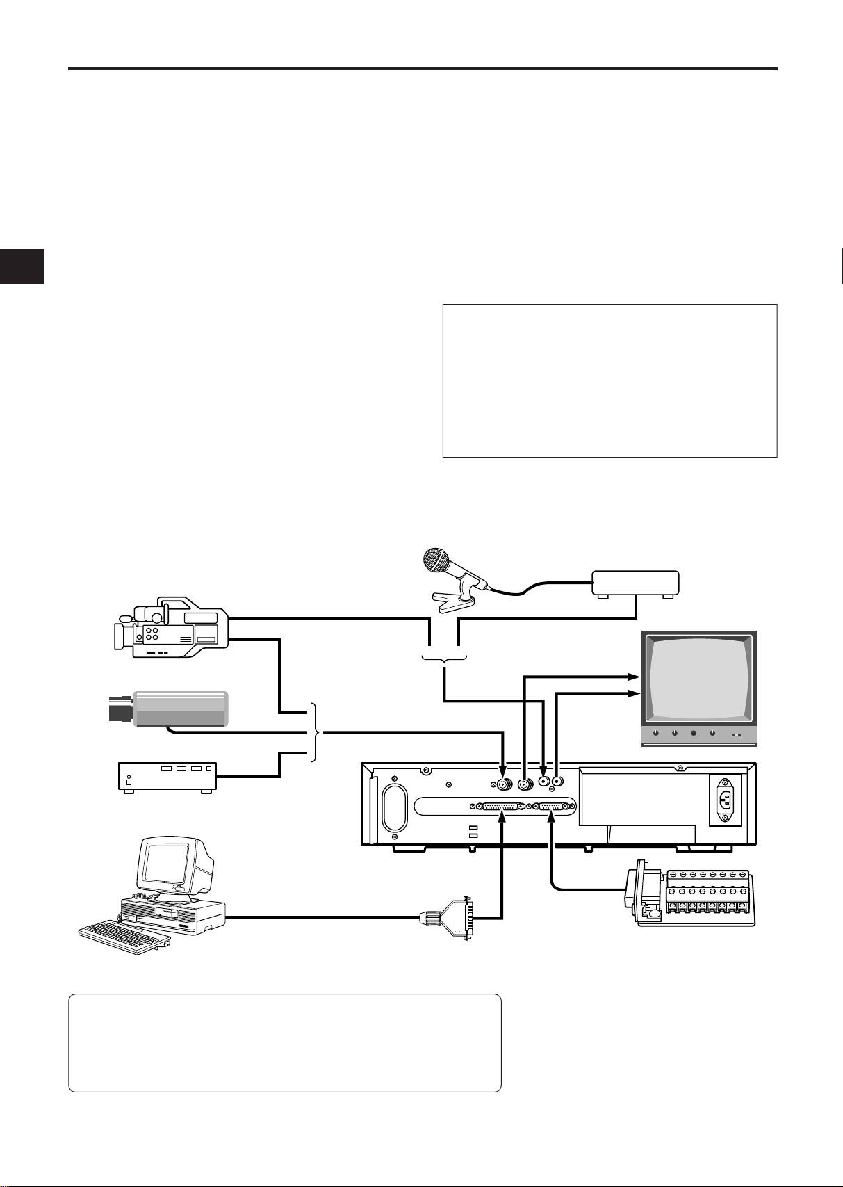
VIDEO CAMERA/RECORDER
CAMERA
SWITCHER
PERSONAL COMPUTER
(with RS-232C jack)
RS-232C reverse type cable
MICROPHONE
PREAMP
MONITOR
15-PIN ADAPTER (provided)
It is necessary to connect
*
to suit your purpose.
Functions of RS-232C Connector Pins
1. Ground 2. Data transmission
3. Data reception 4. Connected to pin 5.
6. Connected to pin 20. 7. Ground
8 ~ 19 and 21 ~ 25. Not connected.
9
Note: The RS-232C is a standard
null-modem cable that can be
purchased locally.
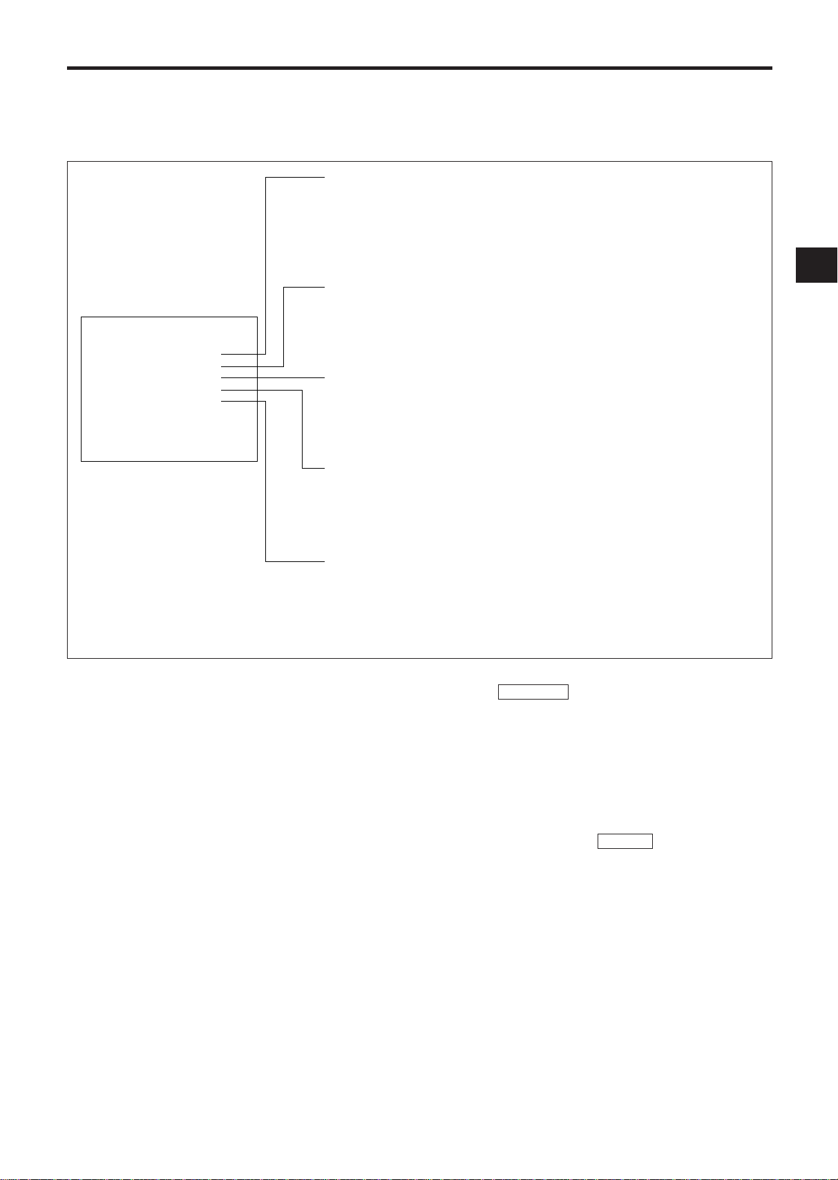
EXTERNAL CONNECTIONS
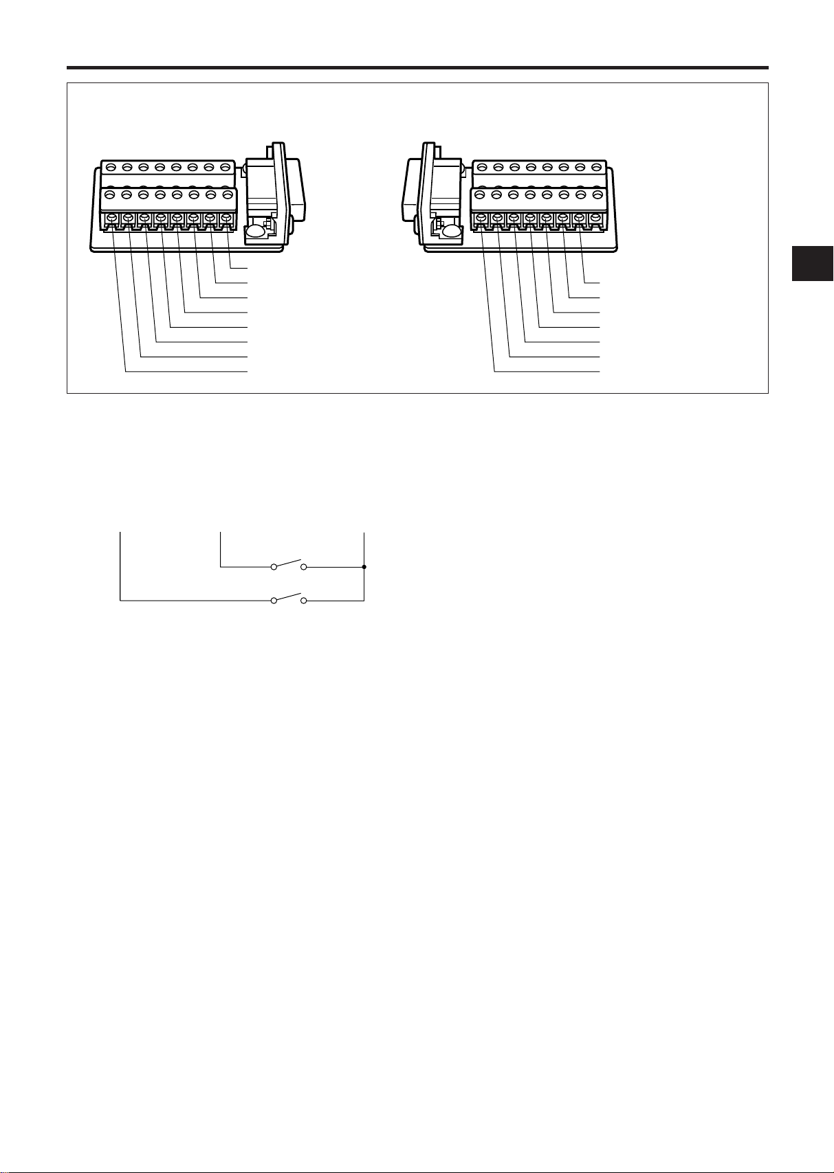
Pin Arrangement of 15-Pin Adapter
q ALARM (A) IN
w ALARM OUT
e ONE SHOT IN
r TAPE END OUT
t TAPE END RESET
o CAMERA SW OUT
!0 REC START IN
!1 REC OUT
!2 LOW TAPE OUT
!3 REMOTE IN
!4 REC CHECK IN
!5 GND
y WARNING OUT
u ALARM B IN
i TIME ADJUST
1110954321
87615141312
ALARM (A) IN/ ALARM B IN
You can connect two devices including an alarm
switch with a resistance of 1 kohm or less or a door
sensor. Connect pin q or u to pin !5 (ground)
through the switches.
ALARM (A) IN ALARM B IN GND
qu !5
Notes:
• Do not apply a voltage to pin q, u or !5.
• If an alarm is input to the ALARM (A) IN terminal
when an alarm is being input to ALARM B IN, the
input at ALARM (A) IN has priority. However, an
alarm at ALARM B IN is not accepted when an
alarm is being input to ALARM (A) IN.
• The recording conditions are different for the
alarms input to the ALARM (A) IN and ALARM B
IN terminals. See page 19 for details.
ALARM OUT
Approx. 12V is applied to pin w during an alarm
recording.
Notes:
• When you have selected “PULSE” in the “ALARM
OUT” menu in the ALARM display, approx. 12V
pulses will be applied to the output after the
alarm recording ends.
• When you have selected “DURATION” in the
“ALARM OUT” menu in the ALARM display, no
voltage is applied after the alarm recording ends.
• The output impedance is approx. 100 ohm.
ONE SHOT IN
One shot recording is possible when pin e is
shorted to pin !5.
Note: Do not apply a voltage to pin e or !5.
TAPE END OUT
Approx. 12V is applied to pin r when the tape
reaches the end.
Notes:
• This does not operate when you have selected
“REWIND, RE-REC” in the “RECYCLE FUNCTIONS” menu in the ALARM display or you have
selected “REWIND, STOP IF ALARM” and no
alarm recording has been made.
• The output impedance is approx. 100 ohm.
TAPE END RESET
The TAPE END OUT can be turned off when pin t is
shorted to pin !5.
Note: Do not apply a voltage to pin t or !5.
10
EXTERNAL CONNECTIONS (Continued)
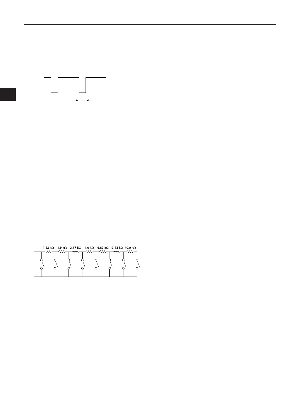
5±2 ms
0~0.4V
4.5~5.5V
!3
!5
STOP PLAY STILL REW F.ADV F.F RECMODE UP
CAMERA SW OUT
Pin o outputs the following signal each time a onefield image is recorded. You can combine this with
a video camera switcher which can be controlled
externally.
The output timing can be specified using the SELECTION MENU screen.
REC START IN
Recording is started when 5 ~ 12V is applied to pin
!0.
REC OUT
Approx. 5V is applied to pin !1 during recording.
The output impedance is 4.7 kohm at this time. The
output stops when recording is interrupted.
LOW TAPE OUT
During recording, when the digital counter counts
up to “32400”, approx. 12V is applied to pin !2. Use
this function as a reference to judge when the tape
is near its end.
The output stops when a TAPE END RESET pulse is
input or the EJECT button is pressed.
Note: The output impedance is approx. 100 ohm.
TIME ADJUST
When two or more of this VCR model are used, connect via these terminals. With only one VCR,
specify TIME ADJUST: MASTER, in [OPTIONS]
items on the CLOCK SET display. Specify TIME
ADJUST: SLAVE (default setting at the factory) for
all other VCRs. Each time “2:00:05” is reached, the
VCR set to MASTER transmits pulses for adjustment
to the VCRs set to SLAVE. When the VCRs set to
SLAVE receive these pulses, their clocks will adjust
to the same time as the clock in the VCR set to MASTER.
Note: Be sure to set only one VCR to MASTER. If no
VCR is set to MASTER, or two or more VCRs are set
to MASTER, the TIME ADJUST function will not
operate normally.
REMOTE IN
This VCR can be remote controlled when the following circuit is connected to pin !3.
The above resistance values have a tolerance of
±2%.
REC CHECK IN
Recording can be checked when pin !4 is shorted to
pin !5 during recording mode. The recorded material is played back for several seconds so that you
can check whether recording is made normally or
not.
WARNING OUT
When an abnormality has occurred in this VCR,
approx. 5V is output to pin y to warn the user.
11
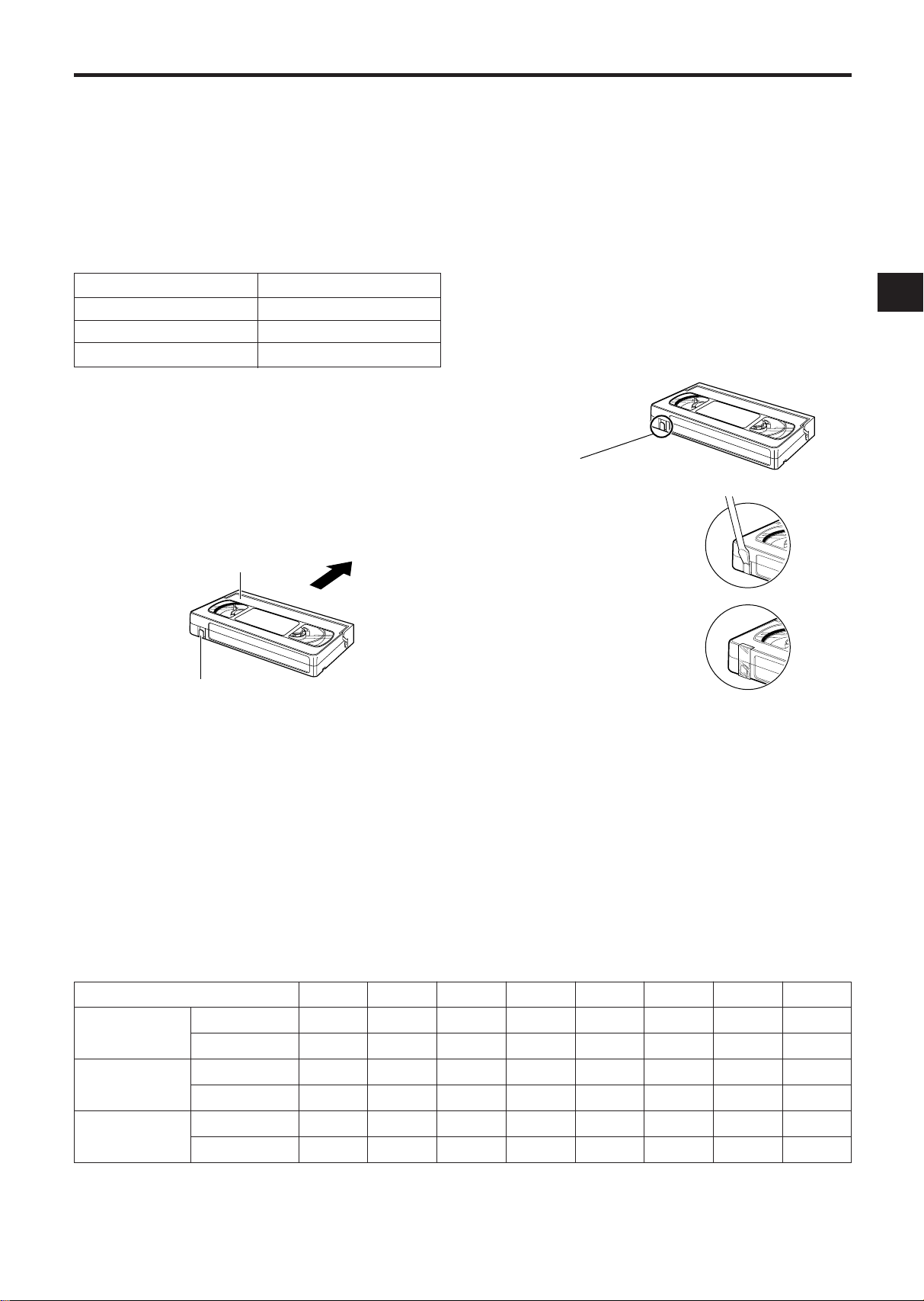
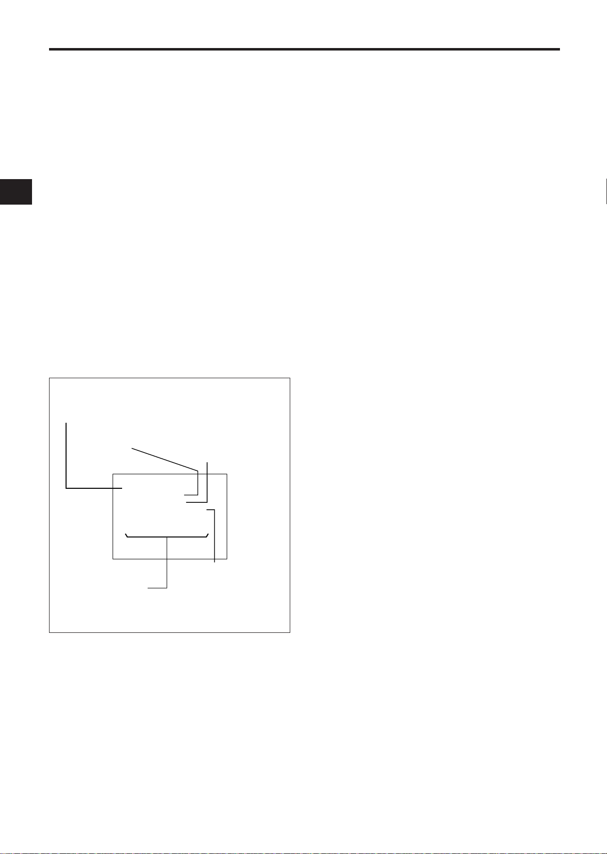
CASSETTE TAPES
SAFETY TAB SLOT
Tape Insertion Position
TOP OF CASSETTE
(THIS SIDE UP)
INSERT
SAFETY TAB
Video Cassette Safety Tab
TO PREVENT
ACCIDENTAL
ERASURE, BREAK
OFF THE TAB
TO RECORD AGAIN,
COVER THE HOLE
WITH TAPE
It is recommended that you use standard grade VHS
video tapes of the following makers:
maxell TDK Fuji
TAPE LIFE
Slower speed operation in time lapse recording
applies stress to video tape. Tapes should be
inspected and, if necessary, discarded after the total
number of complete tape passes (recording and
playback) exceeds the following limits:
Tape Speed Complete Tape Passes
09, 27 50
48, 72, 120, 168, 240 25
00 2
INSERTING A CASSETTE
Note: This is the first step in all VCR operations.
The VCR will not operate without a cassette in place.
To insert a cassette push the cassette through the
cassette compartment door until the VCR mechanism pulls it into the compartment.
The tape-in indicator turns on.
VIDEO CASSETTE SAFETY TAB
To prevent accidental erasure of recorded material,
remove the safety tab from the lower left corner of
the cassette.
Recording is impossible when the safety tab is
removed.
Notes:
• The TAB indicator lights when a cassette without
its safety tab is loaded.
• To record again on a cassette that has its safety
tab removed, cover the tab hole with tape. In the
TIMER mode, the TIMER indicator will flash on
and off if the cassette is inserted without its safety
tab slot covered or intact.
REMOVING A CASSETTE
Before removing a cassette, rewind the tape completely.
To remove a cassette, press the EJECT button. The
cassette will come partially out of the compartment
so you can pull it out.
Tape Speed Mode
Total
Recording
Hours
Pictures/
Second
Audio
E90
E180
RECORD
PLAYBACK
RECORD
PLAYBACK
00
—
—
2.9
—
No
No
09
4.5
9
50
50
Yes
Yes
TAPE LENGTH
The total recording time at each of the eight tape
speeds depends on the length of the tape used.
The table below shows:
1. The total recording time that can be recorded at
each tape speed mode on E90 and E180 tapes.
2. The pictures per second at each speed.
3. The speeds at which audio can also be recorded.
Use the table to select the tape length which gives
the best compromise between tape cost, total
recording time, and elapsed time between pictures.
27
13.5
27
16.7
16.7
Yes
Yes
48
31.5
63
7.14
7.14
No
No
72
40.5
81
5.6
5.6
No
No
120
67.5
135
3.3
3.3
No
No
168
85.5
171
2.6
2.6
No
No
Note: The values in this table are approximate.
240
121.5
243
1.9
1.9
No
No
12

SETUP
CLOCK SET
TIMER DISPLAY
SELECTION MENU 1
Initial Program Function Display Formats
M
ON:
✽✽
09
❲1❳
0
0
0
0
0
0
0
0
0
0
0
0
0
0
:00 :00
a
09
❲2❳
:00 :00
a
09
❲3❳
:00 :00
a
09
❲4❳
:00 :00
a
09
❲5❳
:00 :00
a
09
❲6❳
:00 :00
a
09
❲7❳
,
THU:
✽✽
,
TUE:
✽✽
,
FR I :
✽✽
,
SUN:
✽✽
,
W
ED :✽✽,
SAT :
✽✽
,
:00 :00
a
ELECT
:
M
ODE
SE EEADPCH S
X5
M
S
R:
EVID O
O
T
AU
W
RM:ELCA A S
AL
ENUION
❲❳
SELECTION MENU 2
ALARM DISPLAY
ALARM MEMORY DISPLAY
DULR
AR
M
:TION UMAL
AN
S
SPE D :
09
A
LAR
M
A
LAR
M
A
LAR
M
A
A
RE SIND,
W
DUFURTION
ION
A
E
YDR:AE
:OTU
YE
SET
❲❳
TOPNCIF
TCLECYRE
❲
S
❳
LAR
MMM
1
A00A
2
3
4
5
6
7
8
9
ORYE
❲❳
1–:1–19 FRI990
000:
LOCKCSET
❲❳
TYPO:E
ADJ :US SL AVETTI
M
E
OFFSD
PT I OONS
❲❳
ELECT
EN
E
SEL
TA NEPTD
OF
M
S
EO:
TR UOBL
F
F
OFF
OFF
:
ZBUZ E
O
I
CRT
I:VNEODO
E:RAU C CHECK
OF
ENUION
❲❳
F
LAR
M
A
O:TU
OF
OSEION H T
6F
BA :EUT
LEDS
RA96D00BAUD
ERC:
On-Screen displays are provided to aid setup of the
programmable functions. The six functions on the
Program Menu appear individually on the monitor
in this order.
1. CLOCK SET
2. TIMER
3. SELECTION MENU 1
4. SELECTION MENU 2
5. ALARM
6. ALARM MEMORY
Note: If the VCR is not turned on for about 720
hours after the built-in battery is fully charged (after
the VCR is turned on for more than 48 hours), the
TIME/DATE display will be cleared.
SELECTING A FUNCTION TO BE PROGRAMMED
The program menu will always begin with the
CLOCK SET function, followed by the TIMER,
SELECTION MENU 1, SELECTION MENU 2,
ALARM, and then the ALARM MEMORY functions.
Although the program menu always follows this
order, it is possible to skip any of the available functions during the selection process.
To select the desired program function (and to move
from one program function to the next), press the
PROGRAM button repeatedly until the desired function display format appears on the monitor.
After the desired function has been selected, follow
the corresponding procedure to set that function.
SETTING THE PROGRAM FUNCTION(S)
The first step in each programming procedure is:
“Press the START/STOP button”. The system
allows up to five minutes for any one function setting to be completed after the START/STOP button
is pushed. If no change/setting is entered within the
five minutes period, the unit will automatically exit
the selected program function. (If this happens, reselect the desired program function, and follow the
programming procedure for that function.)
The following procedures for setting VCR functions
assume that the desired function has already been
selected.
Note: During programming, holding the SET, UP, or
DOWN button will move/change the displayed information at a rapid rate.
13

SETTING THE TIME AND DATE
FR I1–:1 –19990
000
LOCKCSET
❲❳
TYPO:E
ADJ :US SLAV ETTI
M
E
OFFSD
PT I OONS
❲❳
TIME (HOUR, MINUTE, SECOND)
DATE (DAY, MONTH, YEAR)
DAY OF WEEK: Corrected
automatically to
match the input
date.
CLOCK SET Display Format Description
OSD TYPE (OFF, FULL or HALF)
TIME ADJUST (MASTER or SLAVE)
Use the CLOCK SET display to set the date and time.
1. Press the START/STOP button so that [CLOCK
SET] flashes on/off.
2. Press the SET button. The day flashes on/off.
3. Press the UP or DOWN button until the desired
number appears on the monitor.
4. Press the SET button. The month flashes on/off.
5. Press the UP or DOWN button until the desired
number appears on the monitor.
6. Press the SET button. The year flashes on/off.
7. Press the UP or DOWN button until the desired
number appears on the monitor.
8. Press the SET button. The hour flashes on/off.
9. Press the UP or DOWN button until the desired
number appears on the monitor.
10. Press the SET button. The minutes flash on/off.
11. Press the UP or DOWN button until the desired
number appears on the monitor.
12. Press the START/STOP button: the seconds will
start counting and the clock will start. [CLOCK
SET] will flash on/off again at this time.
13. To display the time/date you have set here on
the monitor screen, press the START/STOP button again to cause [OPTIONS] to flash, and then
proceed with step 2 in item on OSD TYPE on
page 15.
14. Press the START/STOP button three times.
• Make sure that letters [CLOCK SET] or
[OPTIONS] are not flashing.
Notes:
• Perform the same procedure as when setting the
time and date to make corrections after having
set them. The minutes flash on/off when the SET
button is pressed (in step 2 above).
• To record time and date on the tape, display them
on the monitor screen. If they are not displayed
on the monitor, they cannot be recorded on the
tape.
14
SETUP (Continued)
PROGRAM NUMBER
TIMER RECORDING TIME START/STOP
TIMER RECORDING TAPE SPEED
DAY OF WEEK AND PROGRAM NUMBER
1 :TIMER will record for the time set for PROGRAM NUMBER 1
2 :TIMER will record for the time set for PROGRAM NUMBER 2
3 :TIMER will record for the time set for PROGRAM NUMBER 3
4 :TIMER will record for the time set for PROGRAM NUMBER 4
5 :TIMER will record for the time set for PROGRAM NUMBER 5
6 :TIMER will record for the time set for PROGRAM NUMBER 6
7 :TIMER will record for the time set for PROGRAM NUMBER 7
✽ :No recording
TIMER Display Format Description
M
ON:
✽✽
09
❲1❳
0
0
0
0
0
0
0
:00
a
09
❲2❳
:00
a
09
❲3❳
:00
a
09
❲4❳
:00
a
09
❲5❳
:00
a
09
❲6❳
:00
a
09
❲7❳
,
THU:
✽✽
,
TUE:
✽✽
,
FR I :
✽✽
,
SUN:
✽✽
,
W
ED:✽✽,
SAT :
✽✽
,
:00
0
0
0
0
0
0
0
:00
:00
:00
:00
:00
:00
:00
a
SETTING [OPTIONS] ITEMS
OSD TYPE: The TIME/DATE display was not
designed to appear at the factory. If you wish to
record the time/date together with image, perform
the following procedure:
There are two types of TIME/DATE display: FULL
and HALF.
FULL
DATE
POWER LOSS (IF SENSED)
DAY OF WEEK
ALARM COUNT*
20– 2 –19991
6: 2:00 091
RECORDING SPEED (IN TOTAL HOURS)
TIME
* The ALARM Count Number records alarms from 0 to 99
and then resets to 0 and continues counting.
M
OPL NT00A
L
SECURITY LOCK (IF ACTIVATED)
TIMER (IF ON)
TIME ADJUST: When two or more of this VCR
model are connected to pins i TIME ADJUST of
each EXTERNAL INTERFACE jack, the clocks in both
VCRs can automatically be set to the same time
(TIME ADJUST function).
To use the TIME ADJUST function, set one VCR to
MASTER and any others to SLAVE.
1. Press the START/STOP button twice so that
[OPTIONS] flashes on/off.
2. Press the SET button twice so that the TIME
ADJUST: setting flashes on/off.
3. Press the UP or DOWN button to select the setting
(SLAVE or MASTER).
4. Press the START/STOP button again. The selected setting will light.
Notes:
• You can set OSD TYPE and TIME ADJUST after
you have set the date and time.
• The TIME ADJUST function operates only when
the VCRs are turned on. Therefore, turn the VCRs
on around 2:00:05. This function will not operate
if the times on the MASTER and SLAVE VCRs drift
by more than one hour and 30 minutes.
HALF
DATE
No display
20– 2 –19991
6: 2:001
TIME
OFF
No display
1. Press the START/STOP button twice so that
[OPTIONS] flashes on/off.
2. Press the SET button so that the OSD TYPE: setting flashes on/off.
3. Press the UP or DOWN button to select the setting
(OFF, FULL or HALF).
4. Press the START/STOP button again. The selected
setting will light.
Note: The position of the TIME/DATE display on the
monitor can be adjusted by using the H-POS and
V-POS button on the front panel.
15
SUMMER TIME FUNCTION
Set the summer time function when a cassette is not
loaded in this VCR.
Press the SUMMER TIME and UP buttons simultaneously in modes other than the timer recording
standby mode; the hour display will be counted up
by one.
Press the SUMMER TIME and DOWN buttons simultaneously to count the hour display down by one.
You can change the hour display in one-hour steps
without any limit by pressing the above buttons.
Note: Summer time cannot be set unless TIME/
DATE is displayed.
SETTING THE TIMER
To set the 24 Hour On/Off Timer function

1. Press the START/STOP button.
Example
•••••
Record
Time
Program number 1
Program number 2
Program number 3
When recording of program
number 3 is terminated, program
number 2 will be recorded for its
remaining time.
The program number (1) flashes on/off.
2. Press the SET button. The start hours flash on/
off.
3. Press the UP or DOWN button until the desired
number appears on the monitor.
4. Press the SET button. The start minutes flash
on/off.
5. Press the UP or DOWN button until the desired
number appears on the monitor.
6. Press the SET button. The stop hours flash on/
off.
7. Repeat steps 3 through 5 to set the stop hours
and minutes.
8. Press the SET button. The timer recording
speed flashes on/off.
9. Press the UP or DOWN button until the desired
number appears on the monitor.
10. Press the SET button after setting the timer
recording speed. The program number of the
next lower line flashes on/off.
11. Repeat steps 2 through 9 to set the program to
the other program numbers.
12. Press the SET button after setting the program
numbers (1) through (7).
The two program event locations of MON flash
on/off.
13. Press the SET button. The first program event
location of MON flashes.
14. Press the UP or DOWN button until the desired
program number appears on the monitor.
15. Press the SET button. The other program event
location of MON flashes on/off.
16. Press the UP or DOWN button until the desired
program number appears on the monitor.
Notes:
• If you do not need to timer record two events
a day, mark either event with an asterisk (✽).
• If two asterisks are displayed, no timer record-
ing is made on that day.
17. After setting two program event locations of
MON, press the SET button. The two program
event locations of the next day of the week
flashes on/off.
18. Press the SET button. The first program event
location of the next day flashes.
19. Repeat steps 12 through 16 to set the program
event locations up to SUN.
20. Press the START/STOP button when the TIMER
has been set.
Notes:
1. Programming the TIMER function does not activate it. See TIMER recording, page 21.
2. To record the time and date press the PROGRAM
button to display them.
3. When the preset START time is later than the
STOP time, the recording will be made into the
following day.
4. When the START time and STOP time are the
same, a recording will not be made.
5. When the programs for timer recording overlap
each other, recording will be switched to the program with the later recording start time.
6. When two programs have the same start time,
the program number with the earlier stop time
has priority.
■ To correct information
1. Press the START/STOP button.
2. Press the UP or DOWN button repeatedly until
the item to be corrected (Program number or
program event location of day of the week)
flashes on/off.
3. When the section to be corrected flashes on/off,
press the SET button.
• Press the SET button again so that only the
digit to be corrected flashes on/off.
4. Press the UP or DOWN button to correct the set
information.
5. After completing the correction, press the
START/STOP button.
16
SETUP (Continued)
VIDEO MODE (AUTO, COLOUR, B/W)
• Use during recording or playback if the video signal is unstable,
etc.
AUTO:
COLOUR:
B/W:
The unit automatically detects the type of the video
input or playback signal and switches to the colour
or black-and-white video signal mode, as appropriate.
Selects the colour video signal mode.
Selects the black-and-white video signal mode.
27~:
ALL:
09 ONLY:
The pulses are output during recording at 27 or a
longer speed mode.
The pulses are output during recording in all modes.
The pulses are output during recording at the 09
speed mode.
SEARCH SPEED (3, 5, 7 or 9 times the normal speed)
• You can select the visual search speed.
ONE SHOT REC (2, 4, 6, 8 FIELD)
• You can select the number of fields to be recorded during one
shot recording.
BAUD RATE (1200, 2400, 4800, 9600 BAUD)
• You can select the transmission speed with the personal
computer.
CAMERA SW (27~, ALL, 09 ONLY)
• You can select the timing with which pulses are output to
switch the camera.
SELECTION MENU 1 Format Description
ELECT
:
M
ODOE
ESLD
I
SE EEADP
E
CH S
X5
M
S
R:
ON ER
:
EC
AU
SHRT6F:
D
A0BD
0BAU
EVID O
T
96
O
T
AAU
W
RM:ECA A S
LL
ENUION
❲❳
SETTING THE VCR FUNCTIONS
The SELECTION MENU 1 screen allows you to select the VCR operations and functions to match the applications.
1. Press the START/STOP button.
The VIDEO MODE option “AUTO” flashes on/off.
2. Press the SET button repeatedly until the item
the setting of which you want to change flashes.
3. Press the UP or DOWN button to select the value
or setting you want.
4. After selecting, press the START/STOP button.
17
SETTING THE BUZZER
ELECT
EN
E
SEL
TA NEPTD
OF
M
S
EO:
TR UOBL
F
F
OFF
OFF
:
ZBUZ E
O
I
CRT
I:VNEODO
E:RAU C CHECK
OF
ENUION
❲❳
F
LAR
M
A
O:TU
OF
TAPE END (ON or OFF)
• To specify whether buzzer turns on or off, synchronized with
pin r TAPE END OUT of the EXTERNAL INTERFACE jack.
ON:
OFF:
Buzzer will keep sounding when tape reaches the end
during recording.
Buzzer will not sound even when tape reaches the end.
TROUBLE (ON or OFF)
• To specify whether buzzer turns on or off when abnormality
occurs in this VCR.
ON:
OFF:
Buzzer will keep sounding if abnormality occurs.
Buzzer will not sound even if abnormality occurs.
NO VIDEO (ON or OFF)
• To specify whether buzzer turns on or off when no video signal
is input during recording.
ON:
OFF:
Buzzer will keep sounding when video signal input stops.
Buzzer will not sound even when input stops.
AUTO REC CHECK (ON or OFF)
• To specify whether buzzer turns on or off if recording is
abnormal after the AUTO REC CHECK function.
ON:
OFF:
Buzzer will keep sounding if recording is abnormal.
Buzzer will not sound even if recording is abnormal.
ALARM OUT (ON or OFF)
• To specify whether buzzer turns on or off when alarm is output.
ON:
OFF:
Buzzer will keep sounding if alarm is output.
Buzzer will not sound even if alarm is output.
SELECTION MENU 2 Format Description
This VCR has a buzzer function.
Use SELECTION MENU 2 to select the times when you wish buzzer to sound.
Note: “OFF” is specified for all buzzer options at the factory.
1. Press the START/STOP button.
The TAPE END option “OFF” flashes on/off.
2. Press the SET button repeatedly until the item
the setting of which you want to change flashes.
3. Press the UP or DOWN button to select the value
or setting you want.
4. After selecting, press the START/STOP button.
To stop buzzer:
1. When lights in the VCR display, press
TAPE END
the EJECT button: The tape will come out and
the buzzer will stop.
2. When “A” lights in the VCR display and also “NO
VIDEO” appears on the monitor screen, the
buzzer will stop when video signal is input.
3. When “REC CHECK” appears on the monitor
screen, press the STOP button: The buzzer will
stop.
4. When alarm indicator flashes in the VCR
ALARM
display, press the ALARM RESET button: The
buzzer will stop.
5. If buzzer function varies in any of the above cases,
the VCR may be abnormal. Press the RESET buttons simultaneously: The buzzer will stop.
However, note carefully that all settings will
return to initial values set at the factory.
Note: You can also stop buzzer by switching ON to
OFF in SELECTION MENU 2.
18
SETUP (Continued)
DULR
AR
M
:TION UMAL
AN
S
SPE D :
09
A
LAR
M
A
LAR
M
A
LAR
M
A
A
RE SIND,
W
DUFURTION
ION
A
E
YDR:AE
:OTU
YE
SET
❲❳
TOPNCIF
TCLECYRE
❲
S
❳
ALARM Display Format Description
DURATION: User programmable length or time the unit
stays in the alarm record mode. (MANUAL, 5 SEC, 15
SEC, 30 SEC, 1 MIN, 3 MIN, 5 MIN, 10 MIN, 30 MIN, 60
MIN or TAPE END)
ALARM RECORDING TAPE SPEED
(09~240)
ALARM READY (YES or NO)
RECYCLE FUNCTIONS
(“REWIND, STOP IF ALARM”, “REWIND, STOP” or
“REWIND, RE-REC”)
ALARM OUT
(DURATION or PULSE)
SETTING THE ALARM
The ALARM function allows the user to set the
recording duration, speed to be recorded and tape
recycle for alarm recordings. When a contact closure occurs at the ALARM B IN input, the VCR automatically enters the RECORD mode at the pre-programmed ALARM recording speed. (See Alarm In,
page 10 for a complete description of the ALARM
sequence.) The ALARM recording duration can last
according to the set value, or until the contact closure is reopened.
The ALARM recording speed can be pre-programmed to 09~240.
The checking signal is automatically recorded on the
tape at the beginning of each ALARM recording.
Later, you can easily locate the start of each recording by using these signals when watching a recorded content. See “ALARM INDEX SEARCH” on
page 23 for details.
See page 15 if you also want to record the date/time.
The TIME/DATE display is set as follows during
ALARM display.
—ALARM stars (✽) will replace the colons (:).
— The recording speed will be changed to 09~240
which was selected at the “SPEED” setting in the
ALARM display.
Notes:
• When the ALARM recording ends, the VCR will
return to the status it was in before the alarm was
input.
• Select 09 at the “SPEED” setting when the duration is within 30 seconds. If the 27~240 speed is
selected, electronic “marks” are not recorded on
the tape and alarm index search will not operate.
1. Press the START/STOP button. The duration setting flashes on/off.
2. Press the UP or DOWN button until the desired
setting appears on the monitor. (MANUAL, 5,
15, 30 SEC, 1, 3, 5, 10, 30, 60MIN, TAPE END)
3. Press the SET button. The record speed setting
flashes on/off.
4. Press the UP or DOWN button until the desired
setting appears on the monitor. (09~240 HR.)
5. Press the SET button. The alarm ready setting
flashes on/off.
6. Press the UP or DOWN button to select the
alarm ready function. (YES or NO)
Select “YES” if you want to start alarm recording even in the normal record or stop mode.
Select “NO” if you do not want alarm recording
in the stop mode.
7. Press the SET button. The alarm out setting
flashes on/off.
8. Press the UP or DOWN button to select the
alarm out function. See “ALARM OUT” on page
10 for details. (DURATION or PULSE)
9. Press the SET button.
The RECYCLE position flashes on/off.
10. Press the UP or DOWN button to select the
mode at the end of tape. See “TAPE RECYCLE”
on page 21 for details.
11. Press the START/STOP button.
Programming for the ALARM has been completed.
19
Caution when input to ALARM (A) IN:
The conditions for recording an alarm input to
ALARM (A) IN are fixed as follows.
Note: The ALARM READY function can be specified
as YES or NO.
[Conditions for recording the input to ALARM (A) IN]
DURATION: MANUAL
MODE: 09
ALARM OUT: DURATION
RECYCLE FUNCTION: REWIND, STOP IF ALARM
 Loading...