


LRC1015, LRC1025, LRC1035
Installation instructions

90
60
50
29
50
105
1
2
1 2
1
2
3
L N
* LRC1025, LRC1035
** LRC1035
**
N L
1-10 Vdc, 20 mA
1-10 Vdc, 25/20 mA
1150 VA
-
+
l max. 30 m
LCC8011
LCC8014
LCC8012
LCC8013
l max. 30 m
l max. 125 m
LCC8024
+
-
RC5
IR
RC5
IR
L
MAINS
N N L
R ≥ 22 Ohm
C = 0.25 μF
R
C
< 3x TRIOS: Σ max. 125 m
< 5x TRIOS: Σ max. 100 m
5x TRIOS: Σ max. 85 m
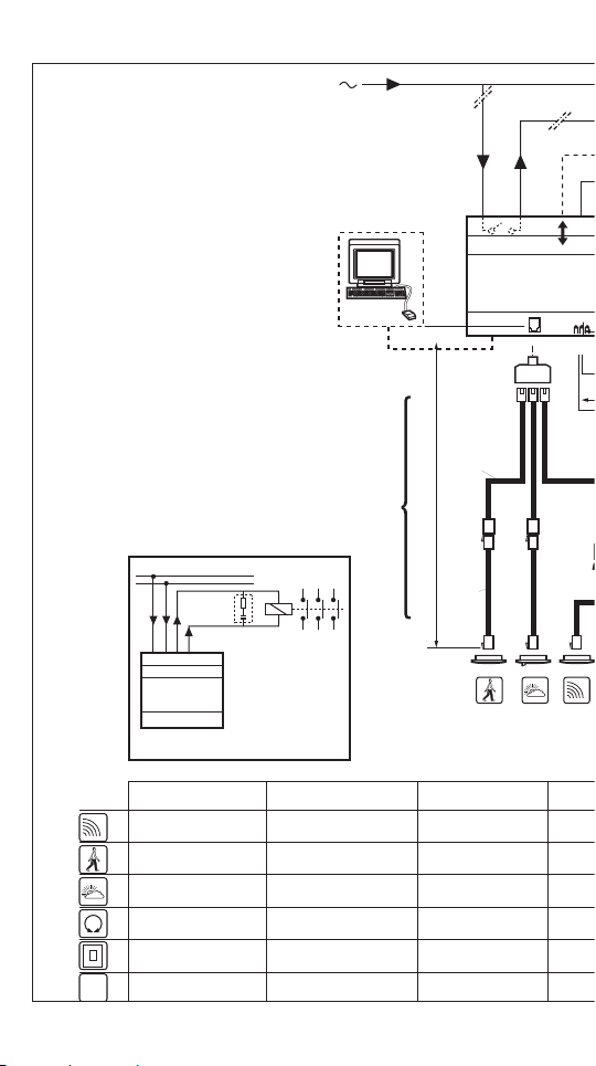
GB
Infrared receiver
Movement detector
Light sensor
Potentiometer
Push-button
Push-button interface
Legend
F
Récepteur infrarouge
Détecteur de mouvement
Cellule photo-électrique
Potentiomètre
Bouton poussoir
Interface bouton poussoir
NL
Infra-rood ontvanger
Bewegingsmelder
Lichtmeetcel
Potentiometer
Druktoets
Drukknopinterface
D
Infrarot Empfänger
Bewegungsmelder
Lichtsensor
Potentiometer
Taster
Tastermodul

***
*
1-10 Vdc, 20 mA
+
+
1-10 Vdc, 25/20 mA
1150 VA
L
N
+
L
N
+
l max. 30 m
l max. 125 m
LCC8024
+
-
RC5
IR
I
Ricevitore infrarosso
Rilevatore movimento
Fotocellula
Potenziometro
Pulsante
RC5-Interfaccia pulsanti
E
Receptor Infrarrojos
Detector de movimiento
Fotocellula
Potenciometro
Pulsador
Codicador pulsadores
S
IR-mottagare
Rörelse detector
Ljussensor
Potentiometer
Tryckknapp
Tryckknappsinterface
LRD
Cu / Fe
HF > 42 KHz
LRC1015, LRC1025 only

LNN L
8 20
A
B
B
A
1
2
230
230 Vac
LRC1015
LRC1025
LRC1035
1-10 Vdc
LRC1025
+
-
8 20
1
2

1-10 Vdc
LRC1035
8 20
2
1
1
2
++
-
1
2
21
Digital input (1/0)
LRC1015, LRC1025
LRC1035
8 20
1
2
-
+
max 125 m
digital I/O
230 V

Analogue input (1-10 Vdc)
LRC1025
LRC1035
8 20
1
2
-
+
max 30 m
1-10 V
230 V
IR
max. 5x
LCC8011
max. 5x
10 mA
50 mA (max.)
9 mA (max.)
max. 3x
max. 1x
3 mA
12 V
5 V
3x + 1x + 3x
2x + 2x + 1x =
5x + 1x + 2x =
sensor cable
230 V

IR
IR
IR
max. 5x
10 mA
max. 3x
max. 1x
10 mA
max. 6x
5 mA
∑ ≤ 50 mA
∑ ≤ 9 mA
3 mA
RC5
3x + 1x + 3x
2x + 2x + 1x =
=
RC5
5x + 1x + 2x =
sensor cable
Telejack connectors
1
2
3
6
5
4
AWG 26
1
2
3
6
5
4
RJ-12 (6p / 6c)
A
6 5 4 3 2 1
1 2 3 4 5 6
Pin/core
1
2
3
4
5
6
Colour wire
White
Black
Red
Green
Yellow
Blue
Function
+12 Vdc
GND
+5 Vdc
IR
RC5

IR adress A1
LRC 1020
Dim out
TRIOS
I II III
2
= O.K.!
1
2
3
4
5
Channel
G
1
IR address
1/B
3/D
5/F
0/A
2/C
4/E
6/G
7
Operating Mode
Group Address
Channel Address
Flashing LED
8 9
Datasheet
IRT8030

3222 609 25605
02/2008
Printed in EU
Data subject to change
http://www.philips.com/lightingcontrols
Technical information
- Mains supply 230 Vac +/- 10 %; 50/60 Hz +/- 5 %
- Output switching 1150 VA, any type of lighting load
- Output regulation LRC1015 N.A.
LRC1025 1 x 1-10 Vdc; 25 mA current sinking
LRC1035 2 x 1-10 Vdc; 20 mA current sinking
each
- Analogue input LRC1015 N.A.
LRC1025, LRC1035 screw connections for a 1-10 Vdc
(current sinking) potentiometer.
- Digital input Screw connections for push-button.
Digital input is active low
- Screw connections All screw connections are suited for solid or stranded
wires with a cross-section of 0.5 .. 2.5 mm
2
.
- Sensor input 1 modular socket for 6-pin telejack plug or branching
connector. Sensor input suited for: - IR receiver
- Light sensor
- Movement detector
- Programming input LRC1035 only: Connector (9-pin; D-sub) for
PC programming tool
- Mounting Suited for mounting on a 35 mm DIN rail. Must be
mounted inside an installation cabinet or similar
- Operating conditions Operating temp. 5 .. 55 ºC
Rel. humidity 15 .. 90 %, no condensation
- Safety
Housing Protection class IP20
Flammability class. V0
Mains part Double insulation (4 kV) between:
- mains and sensor part,
- mains and control voltage
Sensor part Basic insulation (2 kV) between
- sensor part and control voltage
Sensor cables Cables comply with signal wire rules.
Ballasts/dimmers Connected dimmers and regulating ballasts shall have at
least basic insulation.
Safety compliance IEC 669-2
 Loading...