How it Works
Log In / Sign Up
Buy Points
How it Works
FAQ
Contact Us
Questions and Suggestions
Users
Philips
Loading...
L
Lifecare PLV-100
2
Lighting Contact Centre
2
LightStrip
Lightstrip Outdoor
Lightstrip Plus
Lightstrip Plus Extension
Lightstrips
Limpiador de lentes de CD
Limpiador de VHS
LINEA
Link
LINK-51SD
LiqArt
LiqFaz
LiqFaz Filter
Liquide de nettoyage
Lirio
Lirio Aplique
3
Lirio Colgante
5
Lirio Deckenleuchte
Lirio Foco
Lirio Foco empotrable
Lirio Lampadaire
Lirio Lampe à poser
Lirio Lámpara de mesa
2
Lirio Lámpara de pie
2
Lirio Pendelleuchte
Lirio Plafón
Lirio Spot
Lirio Spot à encastrer
Lirio Suspension
Lirio Tischleuchte
Lirio Wandleuchte
Lisseur
2
LivingAmbience Lámpara de mesa
Living Color Light
LivingColors
17
LivingColors Aplique negro
LIVING COLORS AURA
3
LivingColors Bloom blanca con mando a distancia
2
LivingColors Bloom blanca sin mando a distancia
LivingColors Generation2
LIVING COLORS IRIS
2
LivingColors Lampe à poser
2
LivingColors Led Lamp Mini
LivingColors Lámpara de mesa
LivingColors Lámpara de pie baja transparente
LivingColors Mando a distancia
LivingColors Micro
24
LivingColors Mini negra
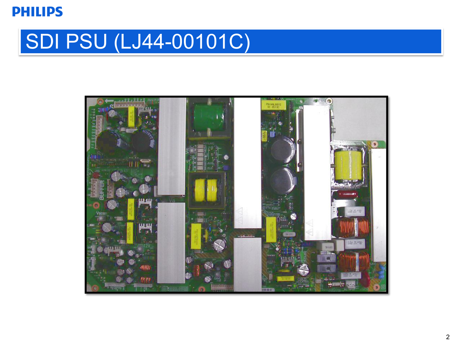
LJ44-00101C PSU
LLC1681
LLC7020
LLC7260
LLC7262
LLC7280
LLC7310
LLC7315
LLC7730
LLC7740
LLE15180X
LLE15370X
LLE16045X
LLE16120X
LLE16350X
LLE18010X
LLE18040X
LLE18100X
LLE18150X
LLE18300X
LM111
2
LM111F
LM111FE
lm111x
LM117
LM124
LM124F
LM124N
lm124x
LM139
lm139ax
LM139-BCA
LM139F
LM139N
lm1875
LM193
LM193A
LM193FE
lm193x
LM211
2
LM211D
LM211N
LM219
LM219F
LM224
LM224D
LM224F
LM224N
LM224NB
LM239
Loading...
Loading...
Nothing found
LJ44-00101C PSU
Schematic
76 pgs
3.34 Mb
0
Table of contents
Loading...
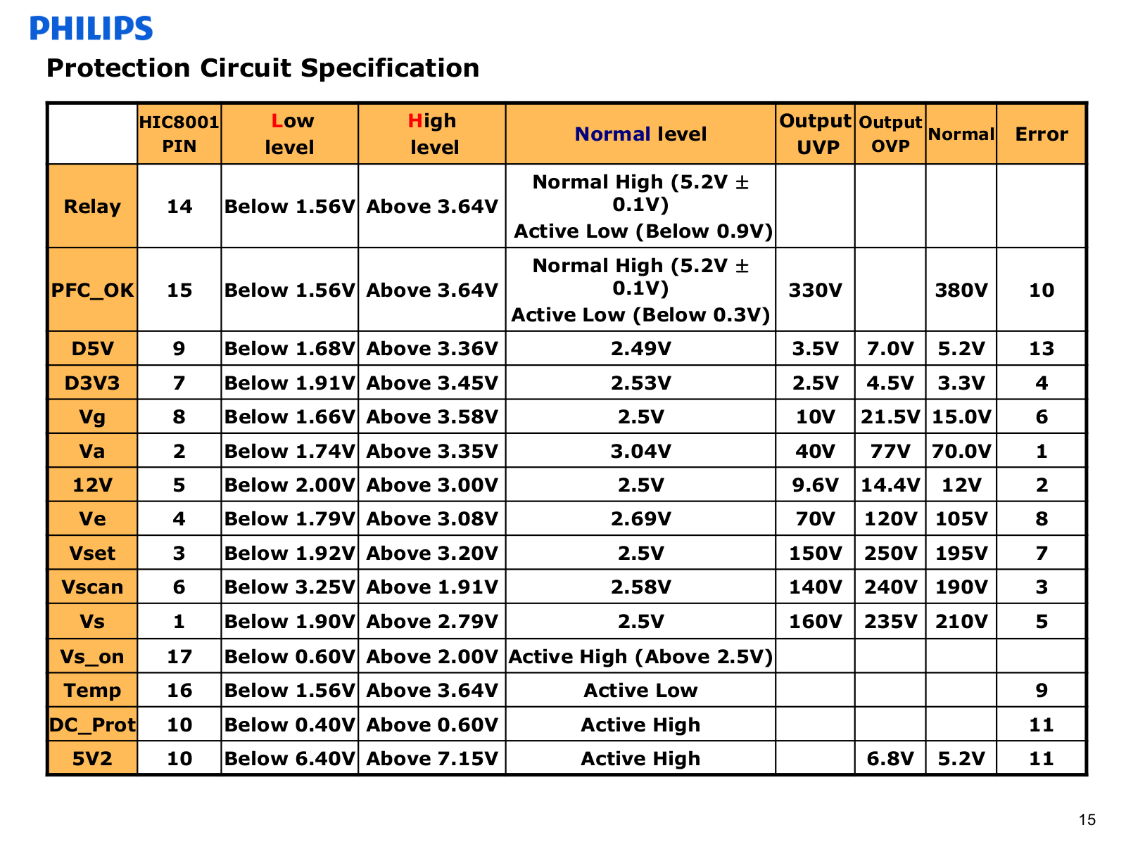
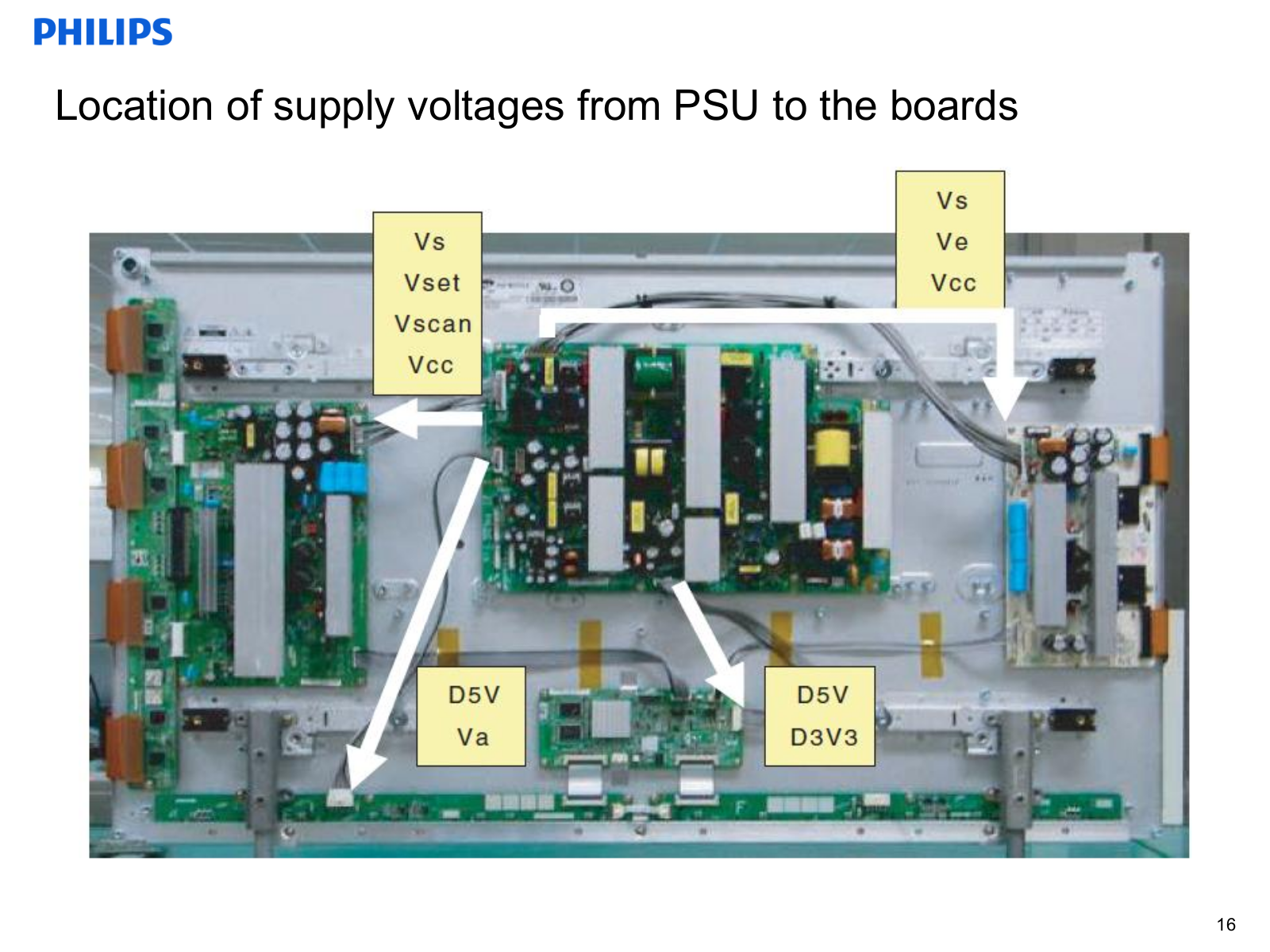
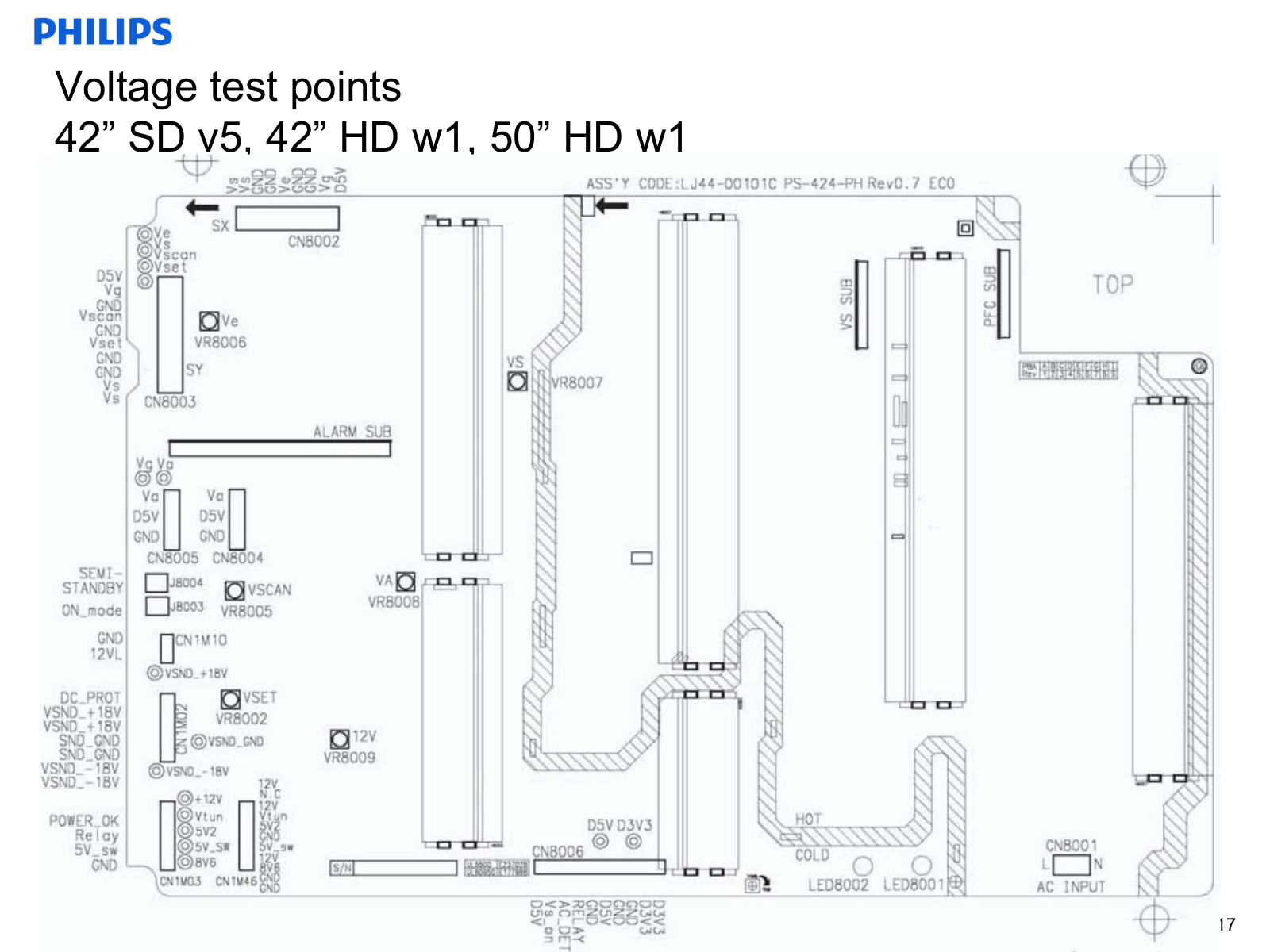
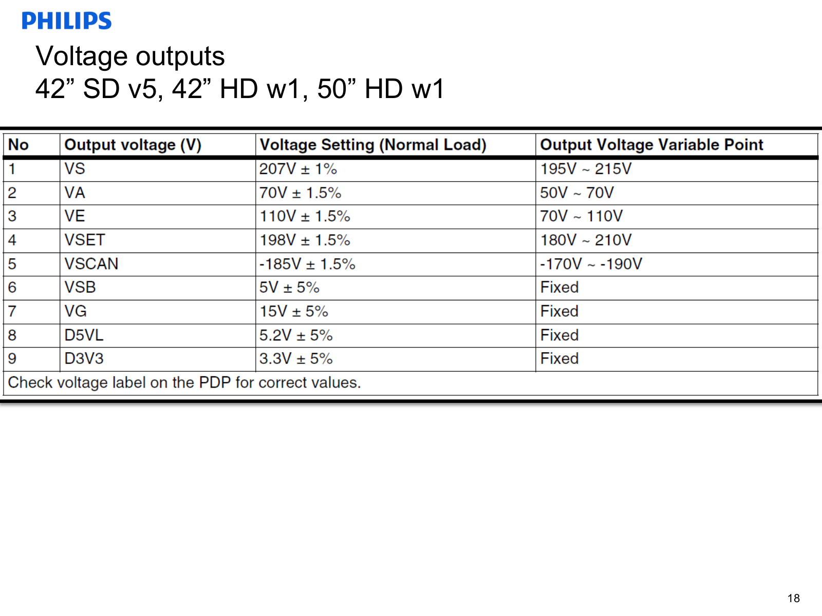
Philips LJ44-00101C PSU Schematic
...
Philips Schematic
Download
Specifications and Main Features
Frequently Asked Questions
User Manual
Download
Loading...
+
53
hidden pages
Unhide
You need points to download manuals.
1 point = 1 manual.
You can buy points or you can get point for every manual you upload.
Buy points
Upload your manuals
 Loading...