

Page 1
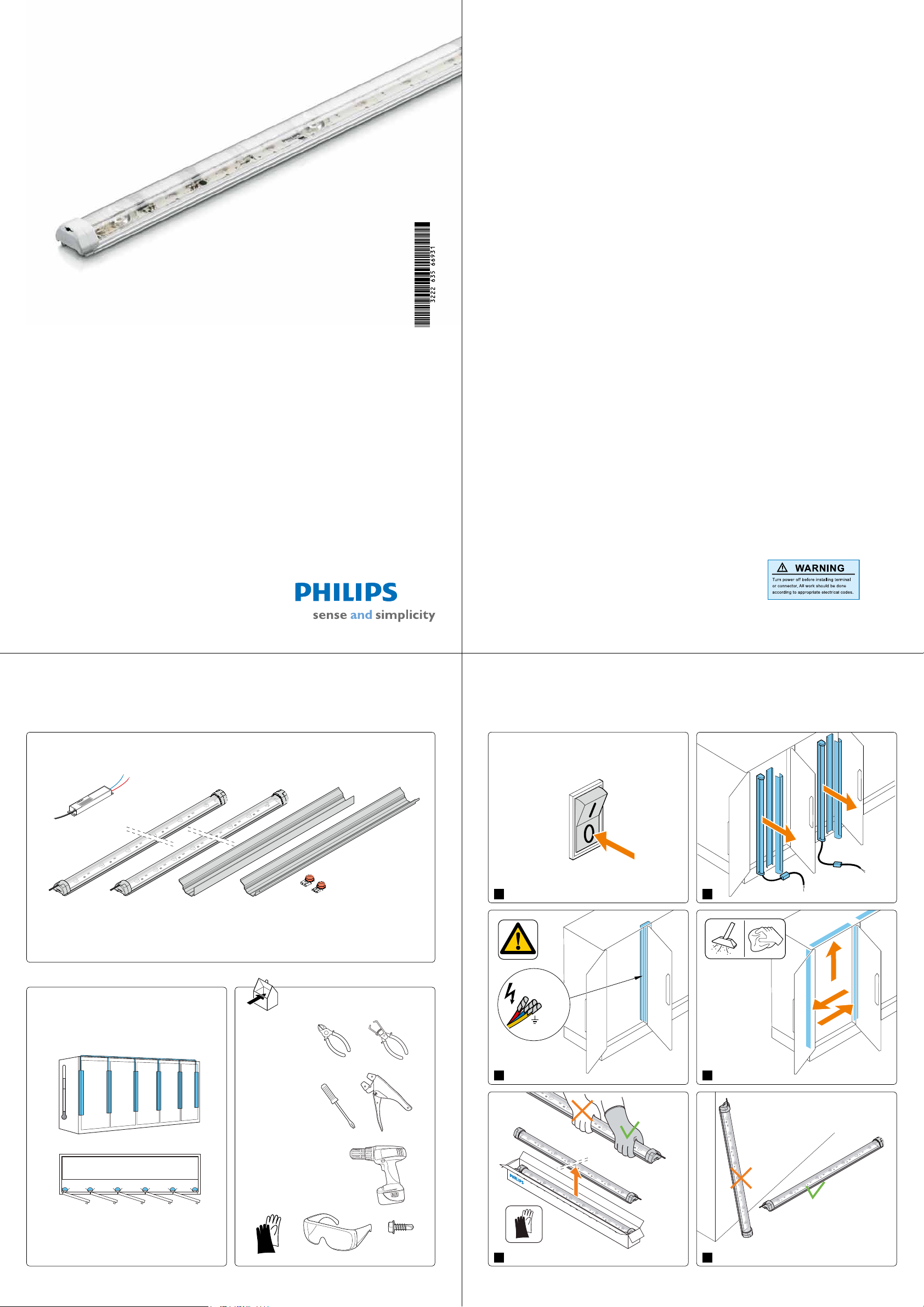
Quick Installation Guide
Xitanium LED Driver
100W - 24V DC
Mounting Profile (Center)
(CTR)
LS SB ConnectorLDM side mounting
extrusion (SD)
LDM405 HE (Center)LDM405 HE (Side)
Side
Center
Side
ediSediS Center Center Center Center
+10 °C
0 °C
-
25 °C
Afnium LED display module LDM405 HE Value-plus
2
Important
Please take the time to read this installation guide before installing the Afnium LED modules
and Xitanium LED drivers. This guide contains important information and notes regarding
product installation and operation.
Warnings
• The installation guide does not supersede local and (inter)national regulations for electrical
installations.
• The Philips Afnium LED module and Xitanium LED driver must be installed by a
professional electrician in accordance with local applicable and appropriate electrical codes
and the installation instructions provided by Philips.
• Please note that the Xitanium LED driver should be built into an enclosure
(mullion/kickplate) [ Tcase max 90 ºC (194 F)].
• The Philips Afnium LED module is designed to be connected to a circuit from a class II
power source with energy-limited supply. These products have not been evaluated for use
when connected to a power source that does not comply with class II voltage and energylimited supplies. Connection to input voltage will damage the module. Although the module
is fully insulated and unsafe situations are unlikely to occur, the module will be damaged
beyond repair if it is connected to input voltage.
• Before installation, maintenance or cleaning, always rst switch off or disconnect the power
and follow appropriate safety procedures.
• Before removing any lens covers or uorescent lamps, always rst switch off or disconnect
the input power to the lighting system.
• Do not tape the Philips Afnium LED module behind the display case mullion or door frame.
• Take care not to damage the existing (heating) wiring in the door frame when installing the
Afnium LED system.
• Do not attempt to replace the power cable to the Philips Afnium LED module because
this cable is permanently attached to the module.
• Do not make sharp bends with electrical wires.
• Please note that the electrical wire colors may differ based on the installed or selected
refrigerated system. The position of the (original) ballast may also differ.
• Due to the variety of designs and brands of refrigerated cases, you may need to use
customized brackets to t the specic type you are using. If you require further support,
please contact your local Philips sales organization.
• This product is designed for damp and dry locations only.
Product and tools
Cleaning
Use a damp cloth and a mild cleaning agent. Do not wipe the module with a dirty or very
wet dishcloth or towel because they may leave residue that can damage the unit.
Do not use abrasive cleaners, scouring pads, steel wool, bleach or cleaners containing bleach
as that these products can scratch and damage the unit.
3
4
Start
Module Placement
1 2
3 4
5 6
Page 2

Side Side
Click
Click
Click
Module Installation
CenterCenter
A
A
A
A
A
Tcase max. 70 ˚C
Switch
Connector
Xitanium LED Driver
100 W/24 V DC
Side
Center
Center
Center
Side
Load driver to maximum of 80 watts
Installation side module / Installation center module
3. After the pro le installation, cover any
4. Remove entire
plastic lm over
mirror from the side
mounting pro le after
installation of the
side mounting pro le.
Peel from one end to
another. Be sure not
to leave ngerprints
8
9
on mirror.
5. Insert top of LED
module into the
mounting pro le (one
side at a time).
7
7. Feed wires into
8. Snap remaining
9. Seal all holes
1. Position the mounting
pro le just above bottom
wiring hole and center it
within the mullion.
2. Af x the mounting pro le to
the mullion by driving at least
six self-tapping screws along
its length (top, center and
bottom).
Note: DO NOT drive screws
through components within
mullion.
remaining holes with NSF-approved tape or
the screws from the removed TL system.
Note: DO NOT make sharp bends with
electrical wires.
bottom mullion hole.
exposed module
into the mounting
pro le.
(including the wire
hole) using NSFapproved silicone
or tape or the
screws used in the
removed TL system.
5
6
Wiring diagram
Quantity of Xitanium LED drivers needed per case
Type Light color Power (Watt) Quantity of Xitanium LED drivers
Value-plus LDM405 HE 1500mm(59”) NW Neutral White 17 12 1 1 1 2 2
Value-plus LDM405 HE 1700mm(67”) NW Neutral White 20 14 1 1 2 2 2
Example: Xitanium LED driver conguration for Value-plus LDM405 HE 67”,
20 W center and 14 W side modules
100 W 100 W 100 W
100 W 100 W 100 W 100 W
Center Side 2 doors 3 doors 4 doors 5 doors 6 doors
100 W
6. Slide LED module
down until the
pro le meets the end
cap. (When af xed
properly, the upper
end cap will support
the module and not
allow it to slide any
lower.)
10
11
7
Ordering information
Type Light color 12NC
Value-plus LDM405 HE 1500mm(59”) NW 12W Neutral White 929000 640313
Value-plus LDM405 HE 1500mm(59”) NW 17W Neutral White 929000 640213
Value-plus LDM405 HE 1700mm(67”) NW 14W Neutral White 929000 640513
Value-plus LDM405 HE 1700mm(67”) NW 20W Neutral White 929000 640413
LDM side mounting extrusion 59” 929000 641313
LDM side mounting extrusion 67” 929000 641513
©2012 Royal Philips Electronics
All rights reserved.
Form No. 3222 635 66931
LE-6130-D 02/2012
Philips Lighting Electronics
10275 West Higgins Road
Rosemont IL 60018
Tel: 800-322-2086 Fax: 888-423-1882
Customer Support/Technical Service: 800-372-3331
OEM Support: 866-915-5886
 Loading...