

Page 1
LC07 chapter 1 introduction
Hans Munsters
Philips CE / Euroservice
March 2007
<< introduction >>
<< introduction >>
SERVICE TRAINING
PERSONAL NOTES:
PERSONAL NOTES:
© Copyright reserved 2002 Philips Consumer Electronics Euroservice
<< introduction >>
chapter: 1 page: 1
Page 2
chassis LC7 is successor of chassis LC4
Analogue LCD LC7.1E LA
Analogue PDP LC7.1E PA
Digital LCD LC7.2E LA
Digital PDP LC7.2E PA
LCD 26” to 52”
Plasma 42” to 50”
<< introduction >>
<< introduction >>
SERVICE TRAINING
Philips CE Europe, Euroservice, March 2007
Introduction chapter 1, Slide 2
There will be analogue and digital sets.
Digital sets are able to receive also the analogue channels.
LC7 will be able to drive LCD and PDP panels.
PERSONAL NOTES:
PERSONAL NOTES:
© Copyright reserved 2002 Philips Consumer Electronics Euroservice
<< introduction >>
chapter: 1 page: 2
Page 3
<< introduction >>
<< introduction >>
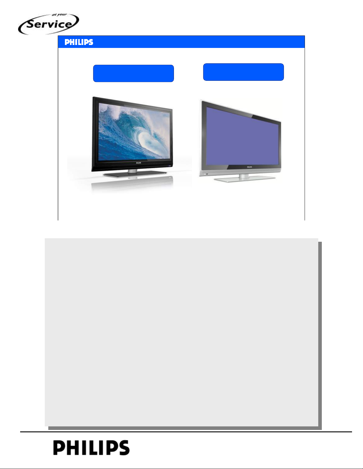
New styling ME7
SERVICE TRAINING
Entry Core Range PDP
Philips CE Europe, Euroservice, March 2007
Entry Core Range LCD
Introduction chapter 1, Slide 3
Example of styling to be used with LC7 chassis.
For plasma sets the bezel will be narrow.
PERSONAL NOTES:
PERSONAL NOTES:
© Copyright reserved 2002 Philips Consumer Electronics Euroservice
<< introduction >>
chapter: 1 page: 3
Page 4
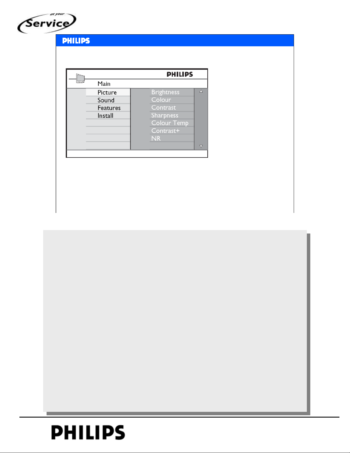
Menu in LC7
1000 pages txt
Clock synchronised from DVB-T transport stream
<< introduction >>
<< introduction >>
SERVICE TRAINING
Autoformat via SCART or WSSB
No Pixel plus in menu (picture processing is based on 50Hz)
Philips CE Europe, Euroservice, March 2007
Introduction chapter 1, Slide 4
Example of the menu used in LC7.
1000 pages txt is used (subpages are visible at the bottom).
Clock in digital set is taken from DVB-T channel
There is no black bar detection, autoformat via status pin 8
and WSSB.
PERSONAL NOTES:
PERSONAL NOTES:
© Copyright reserved 2002 Philips Consumer Electronics Euroservice
<< introduction >>
chapter: 1 page: 4
Page 5
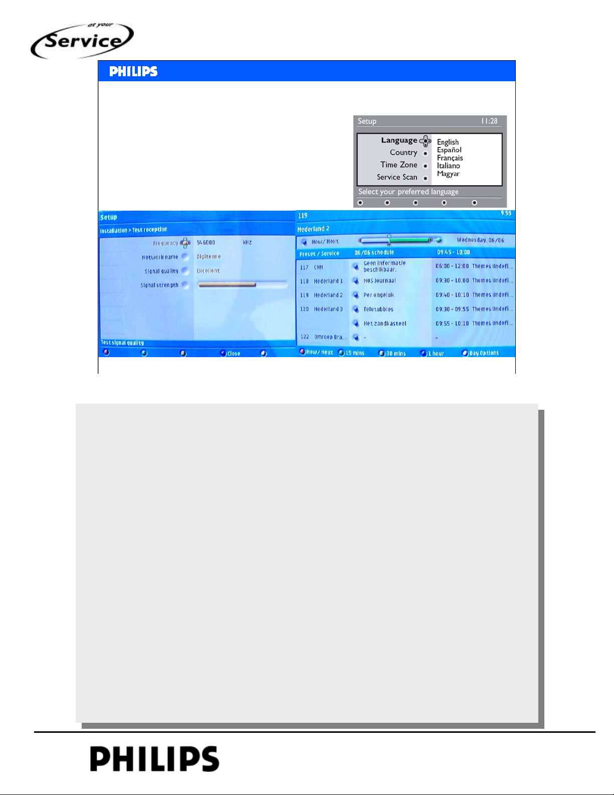
DVB-T reception with LC7
• IBO is used (like LC4 and FTx)
• A/D button on remote control
• Electronic Program Guide
•No SPDIF
<< introduction >>
<< introduction >>
SERVICE TRAINING
Philips CE Europe, Euroservice, March 2007
Introduction chapter 1, Slide 5
Digital mode menu examples.
In digital mode language and country can be changed.
For LC7 there is no digital audio output.
PERSONAL NOTES:
PERSONAL NOTES:
© Copyright reserved 2002 Philips Consumer Electronics Euroservice
<< introduction >>
chapter: 1 page: 5
Page 6
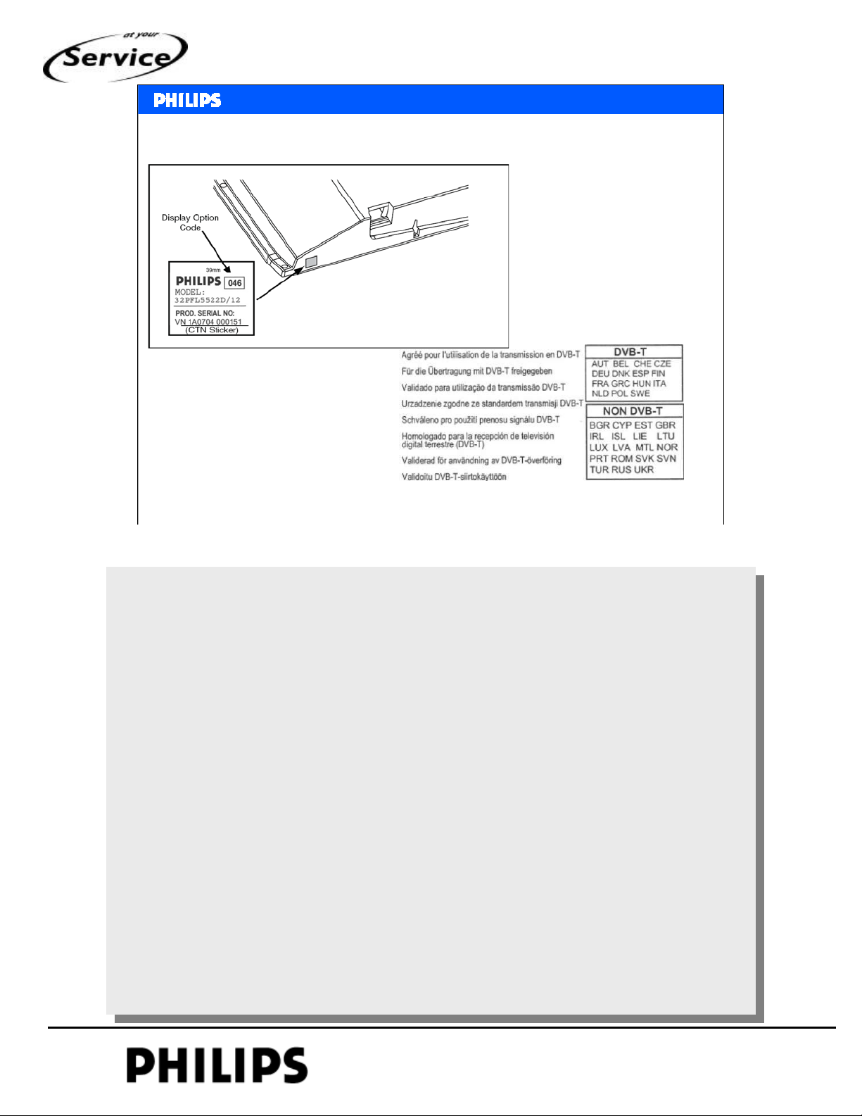
Identification
DVB-T sticker
<< introduction >>
<< introduction >>
SERVICE TRAINING
Philips CE Europe, Euroservice, March 2007
Introduction chapter 1, Slide 6
At the bottom side of the set there is the identification
plate.
On this sticker is the typenumber, serial number and display
code.
On the rear cover is also the sticker for DVB-T countries.
PERSONAL NOTES:
PERSONAL NOTES:
© Copyright reserved 2002 Philips Consumer Electronics Euroservice
<< introduction >>
chapter: 1 page: 6
Page 7
<< introduction >>
<< introduction >>
Digital Analogue
Flat TV 2007 Europe – Core Range
Q4 Top A
BIPLANE DVB-T, 1080P, Pixel Plus 4HD, HD Clear LCD, SD DNM, Ambilight 4
USB, 1080p input, TVTV EPG, Swivel stand
Q4 Top B
MS7 DVB-T, 1080P, Pixel Plus 4HD, HD Clear LCD, SD DNM, Ambilight 3
USB, 1080p input, TVTV EPG, Swivel stand
Q3/Q4 Step
MS7 (32-37-42” LCD), STEP 2K6 (42-50” PDP)
DVB-T, 1080P (37-42” LCD), 100Hz (32” LCD), Pixel Plus 4HD, HD DNM, Ambilight 2
USB, 1080p input, TVTV EPG, Swivel stand
Q2/Q3 Entry+
ME7LB (RHCM-26”) LC06, DVB-T, Pixel Plus, 3D CF, 2
HDMI,1000p
ME7LE (32-42”) BJ, DVB-T, Pixel Plus 2HD, SD DNM, 2 HDMI,
1200p, USB
ME7LB BJ, Pixel Plus 2HD, SD DNM,
2HDMI, 1200p, USB
Q2 Entry
ME7LA, (26-47” LCD), ME7PB (42-50” PDP)
LC06, DVB-T, 1080P (47”), DCC, 3D CF, 2 HDMI,1000p
ME7LA, (26-42” LCD), ME7PB (42” PDP)
LC06, DCC, 3D CF, 2 HDMI,1000p
ME7 (15-23” LCD)
DCC, 2D CF, 1 HDMI, 100p
Q1 Promo
ME7 cost (15-19” LCD)
CC, 2D CF, DVI, 100p
Philips CE Europe, Euroservice, March 2007
Oct-07 Oct-07 Oct-07 Oct-07
15PFL5122
Jul-07
15PFL4122
15”
20PFL5322
20PFL5122 23PFL5322
June-07
19PFL5322
Jul-07
June-07
19PFL432220PFL4122
20” 42w
19/20w 23w 26w 32w 37w 42P
TTM: July
CR: 725
26PFL7532D
32PFL5622D
CR for/05 (UK MHEG1.06) follows /12 (Continental Europe) by 2 weeks
TTM: May
CR: wk714
26PFL5522D 32PFL5522D 37PFL5522D
TTM: May
CR: wk718
26PFL5322 32PFL5322 37PFL5322 42PFL532242PFP5332
TTM: sept.
CR: 732
26PFL3312 32PFL3312
32PFL9632D
TTM: Mar
CR: wk707
32PFL7562D
TTM: Mar
CR: wk706
32PFL7332
TTM: March
CR: 705
TTM: March
CR: 710
TTM: sept.
CR: 732
1080p
May-07 Jun-07
37PFL9732D
Aug-07
ME6
ME6
ME6
TTM: May
CR: wk716
TTM: Oct
CR: wk735
37PFL7532
TTM: May
CR: wk711
TTM: May
CR: wk716
TTM: sept.
CR: 732
37PFL3312
42PFP9532D
TTM: May
CR: wk716
37PFL7662D
TTM: Jun
CR: wk719
TTM: May
CR: wk717
TTM: sept.
CR: 732
42PFP3312
37PFL9632D
37PFL7562D
1080p
Apr-07
42PFL9832D
1080p
42PFL9732D
HD PDP
Jul-07 Aug-07Aug-07Jul-07
42PFL9632D
TTM: Apr
CRV: wk713
HD
42PFL7562D
TTM: Apr
CR: wk714
42PFL7332
TTM: March
CR: wk710
42PFL5522D42PFP5532D 50PFP5532D
TTM: April
CR: wk713
TTM: sept
CR: 732
42PFL3312
CFD
MFD
HD PDP
50PFP9532D
TTM: June
CR: 724
HD
42PFL7682D
TTM: June
Crov: wk721
50w >50w47w
UD
TTM: Aug
CR: 728
52PFL7642D
>50w
Ex EU
1080p
May-07
47PFL9832D
1080p
Jun-07
47PFL9732D
TTM: Apr
CR: wk713
1080p
42PFL7662D
TTM: Sept
Crov: wk734
1080p
47PFL6522D
47PFL5522D
Introduction chapter 1, Slide 7
SERVICE TRAINING
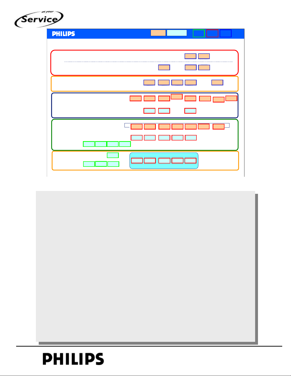
This is range overview for flat-tv 2007, but not all sets
confirmed yet.
UD = Upmarket Displays
MFD = Mainstream Flat Display
CFD = Commodity Flat Display
PERSONAL NOTES:
PERSONAL NOTES:
© Copyright reserved 2002 Philips Consumer Electronics Euroservice
<< introduction >>
chapter: 1 page: 7
Page 8
<< introduction >>
<< introduction >>
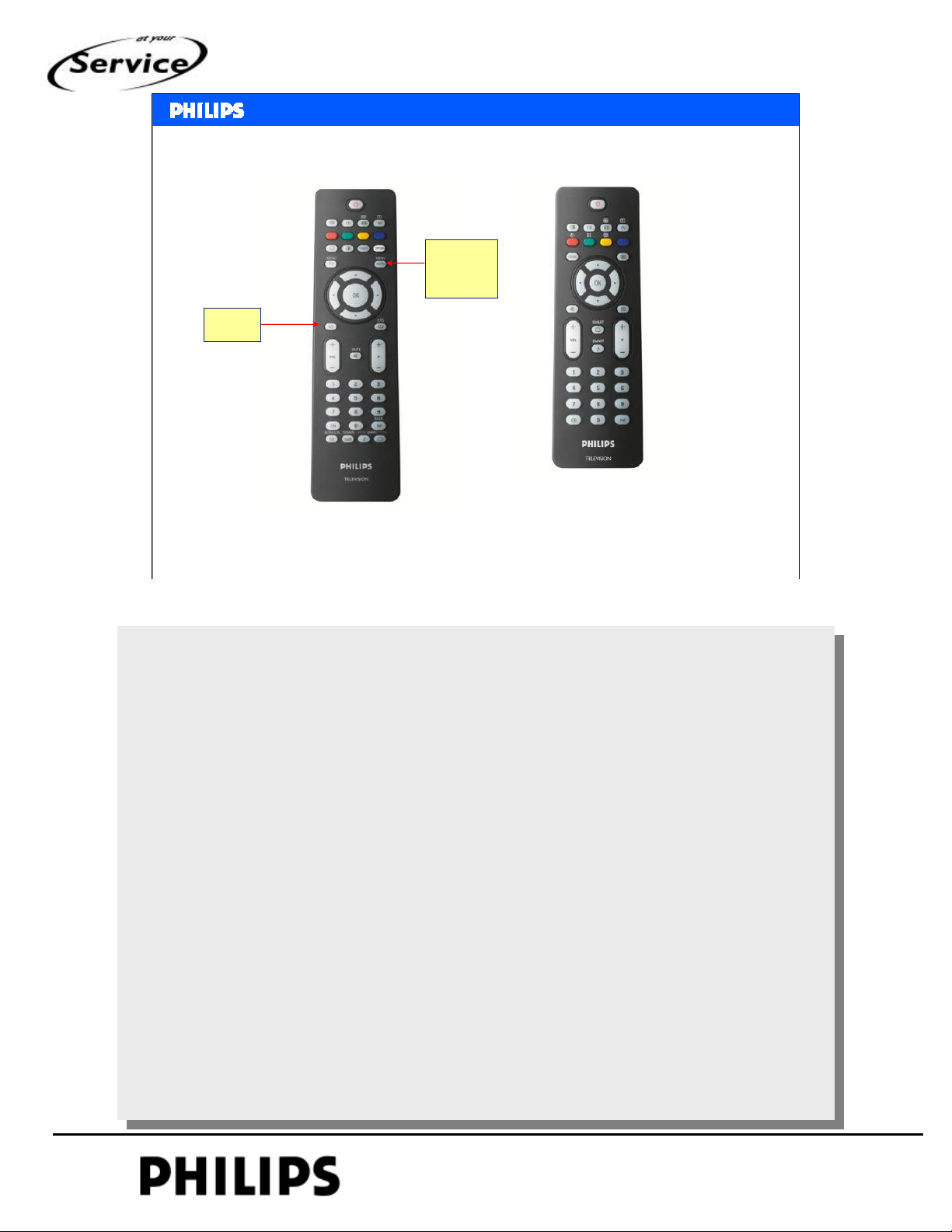
2 types of remote control are used
Digital
menu
A/D
SERVICE TRAINING
For digital sets
RC2034301 313923814201
Philips CE Europe, Euroservice, March 2007
LC7 analogue and BJ3.1E
RC2034302 313923814221
Introduction chapter 1, Slide 8
For sets analogue only is the used remote control more
simple.
This simple remote control is also used in UFD, because in
main stream you must switch between analogue and digital
mode.
PERSONAL NOTES:
PERSONAL NOTES:
© Copyright reserved 2002 Philips Consumer Electronics Euroservice
<< introduction >>
chapter: 1 page: 8
Page 9
New features
• 1080p full HD
• all LC7 sets will support 1080p
• LED ambilight (option)
<< introduction >>
<< introduction >>
SERVICE TRAINING
Philips CE Europe, Euroservice, March 2007
Introduction chapter 1, Slide 9
Extra features will be introduced later.
1080P hardware for sets with 1080P display
1080P is supported by LC7, but not mentioned in the spec.
Optional is ambilight (will be used in AP)
PERSONAL NOTES:
PERSONAL NOTES:
© Copyright reserved 2002 Philips Consumer Electronics Euroservice
<< introduction >>
chapter: 1 page: 9
Page 10
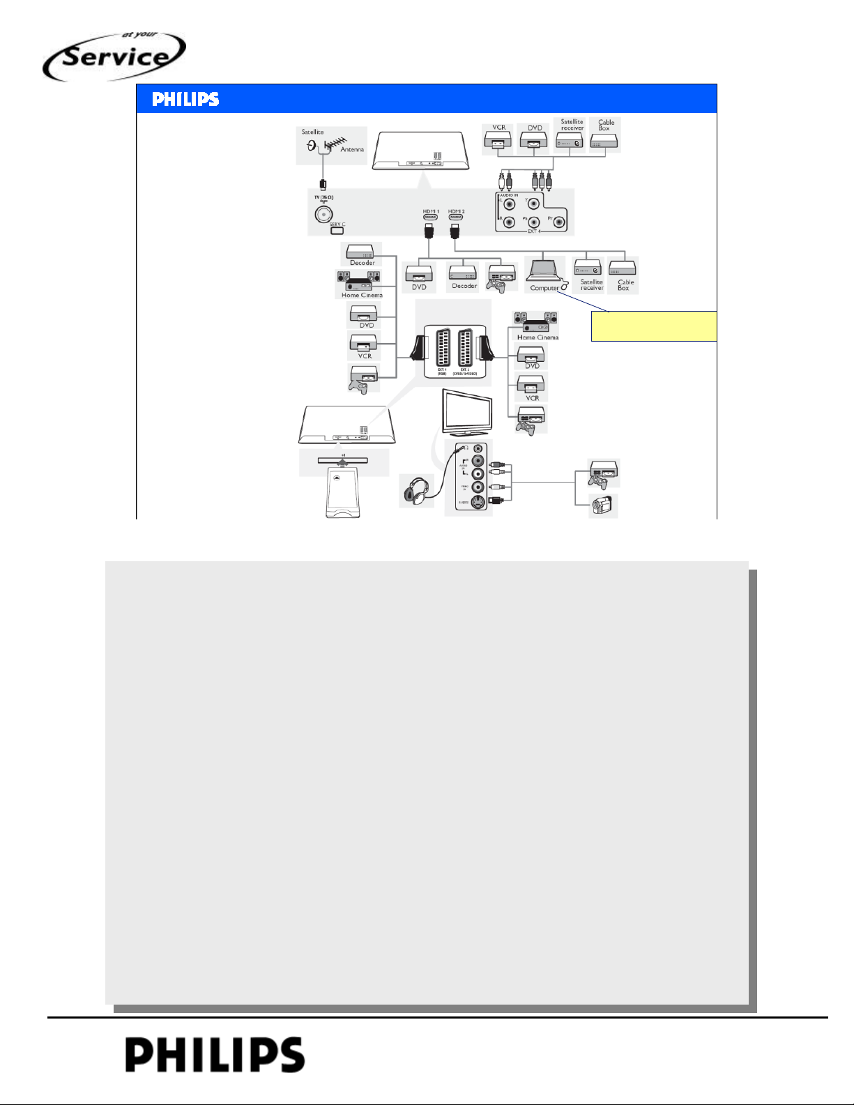
Connectivity
diagram
<< introduction >>
<< introduction >>
no VGA (EU)
SERVICE TRAINING
Philips CE Europe, Euroservice, March 2007
Introduction chapter 1, Slide 10
Connectivity diagram.
Advise how to connect different sources.
Also PC is indicated, is only possible via HDMI (audio via
side connection)
PERSONAL NOTES:
PERSONAL NOTES:
© Copyright reserved 2002 Philips Consumer Electronics Euroservice
<< introduction >>
chapter: 1 page: 10
Page 11
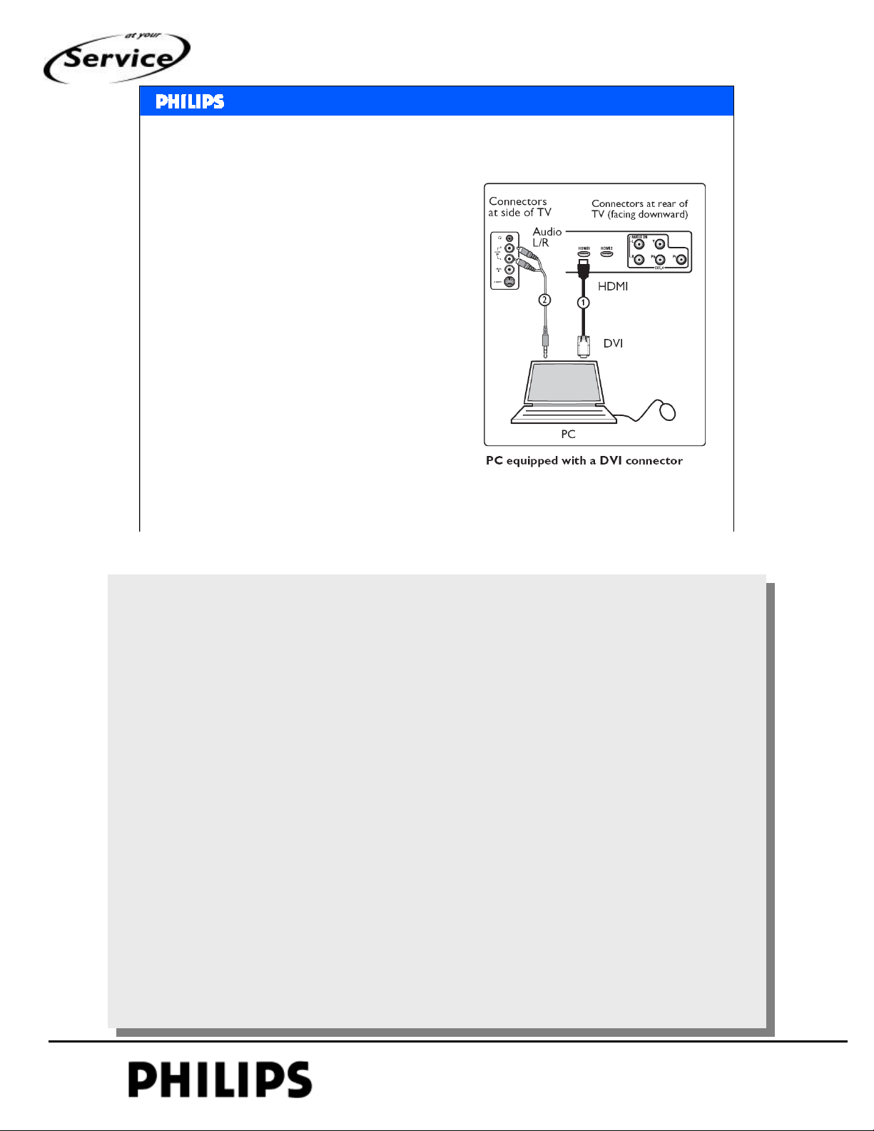
Connect PC to the tv
• Via DVI – HDMI cable
• Audio via EXT3 (front)
<< introduction >>
<< introduction >>
SERVICE TRAINING
Philips CE Europe, Euroservice, March 2007
Introduction chapter 1, Slide 11
PERSONAL NOTES:
PERSONAL NOTES:
© Copyright reserved 2002 Philips Consumer Electronics Euroservice
<< introduction >>
chapter: 1 page: 11
Page 12
<< introduction >>
<< introduction >>
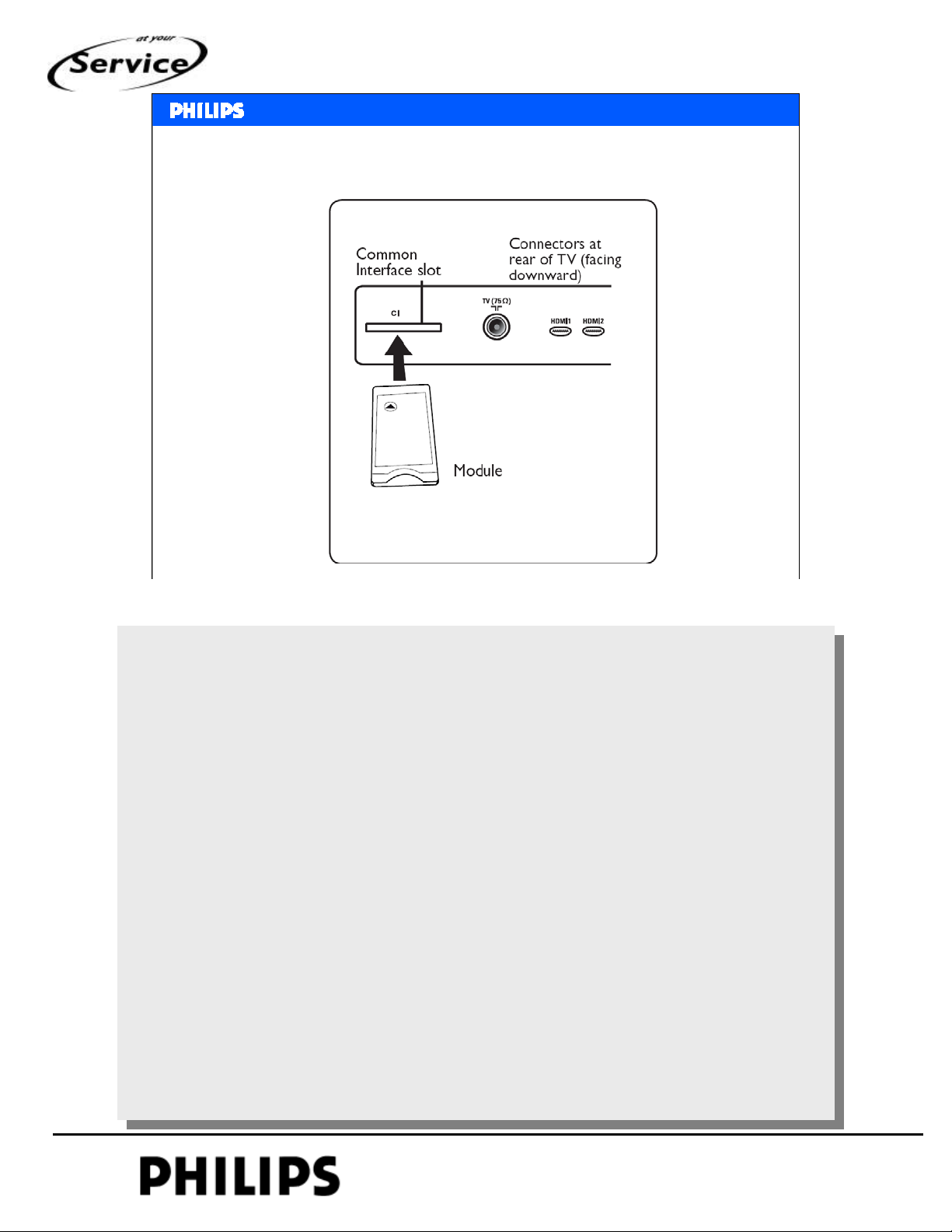
Conditional Access Module
SERVICE TRAINING
Philips CE Europe, Euroservice, March 2007
Introduction chapter 1, Slide 12
Some countries use scrambled DVB-T.
Different coding systems are used, this is decoded via the
module.
This module (Conditional Access Module = CAM) with
smart card can be inserted in the common interface slot.
CAM is not delivered with the set, must be supported by
the local provider.
PERSONAL NOTES:
PERSONAL NOTES:
© Copyright reserved 2002 Philips Consumer Electronics Euroservice
<< introduction >>
chapter: 1 page: 12
Page 13
<< introduction >>
<< introduction >>
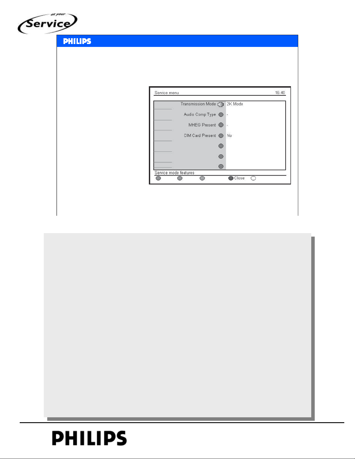
CAM detection in Digital Customer Service Menu
In DCSM there is
information about CAM
detection
1,2,3,6,5,4
Or via digital menu:
Information line, then
SERVICE TRAINING
Green Red Yellow 9759
Philips CE Europe, Euroservice, March 2007
Introduction chapter 1, Slide 13
In the Digital Customer Service mode is an indication
whether the CAM is inserted well.
If your CAM is defective then in this menu is also indicated
NO.
PERSONAL NOTES:
PERSONAL NOTES:
© Copyright reserved 2002 Philips Consumer Electronics Euroservice
<< introduction >>
chapter: 1 page: 13
Page 14
<< introduction >>
<< introduction >>
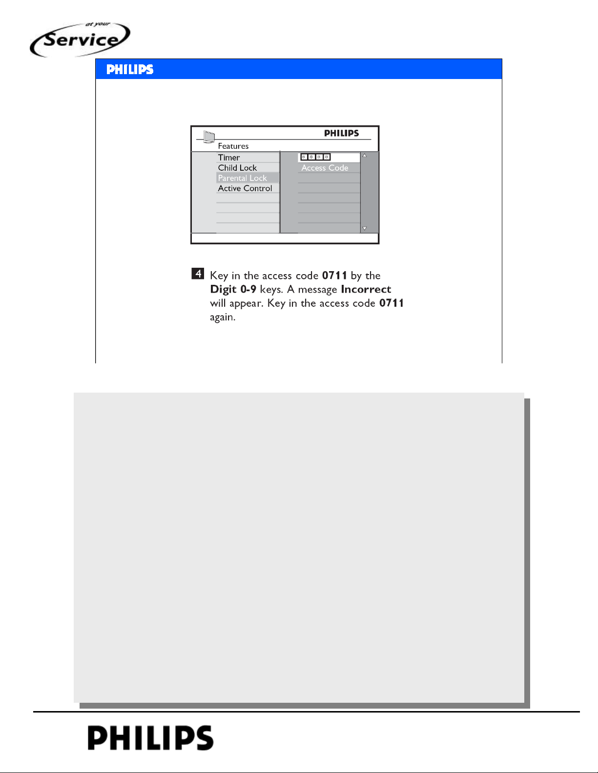
Access code 0711
SERVICE TRAINING
Philips CE Europe, Euroservice, March 2007
Introduction chapter 1, Slide 14
There is an option for parental control (code).
If code is lost, then there is universal code for deblocking.
PERSONAL NOTES:
PERSONAL NOTES:
© Copyright reserved 2002 Philips Consumer Electronics Euroservice
<< introduction >>
chapter: 1 page: 14
Page 15
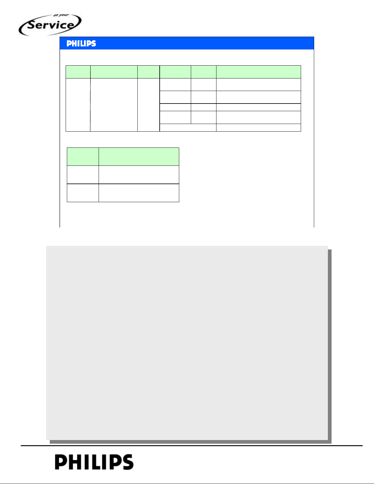
Supported RF transmission
StrokeCountryRegion
/10Europe (Whole)
EUROPE
Supported AV Playback format
Continental Europe
(excluding UK &
Ireland, including
Eastern Europe)
Supported FormatRegion
PAL BG, SECAM, NTSC MEUROPE,
/12
Color
System
SECAM
PAL
Sound
Standard
BGPAL/SECAM/05UK & Ireland
L/ L’
L
DKPAL/ SECAM
<< introduction >>
<< introduction >>
Sound System
NICAM Stereo/ Mono/ Dual,
2CS Stereo/ Dual, FM Mono
NICAM Stereo/ Mono/ Dual, AM Mono
NICAM Stereo/ Mono/ Dual, FM MonoIPAL
NICAM Stereo/ Mono/ Dual,
2CS Stereo/ Dual, FM Mono
MPEG-Audio PCM, 44.1kHz 16bitsDVB-T (For Digital Set)
SERVICE TRAINING
AP,CHINA,
LATAM
Philips CE Europe, Euroservice, March 2007
PAL BG, PAL M, PAL N, NTSC M, NTSC
4.43, PAL 60, SECAM
Overview of supported standards.
No AC3 support
Introduction chapter 1, Slide 15
PERSONAL NOTES:
PERSONAL NOTES:
© Copyright reserved 2002 Philips Consumer Electronics Euroservice
<< introduction >>
chapter: 1 page: 15
Page 16
<< introduction >>
<< introduction >>
SERVICE TRAINING
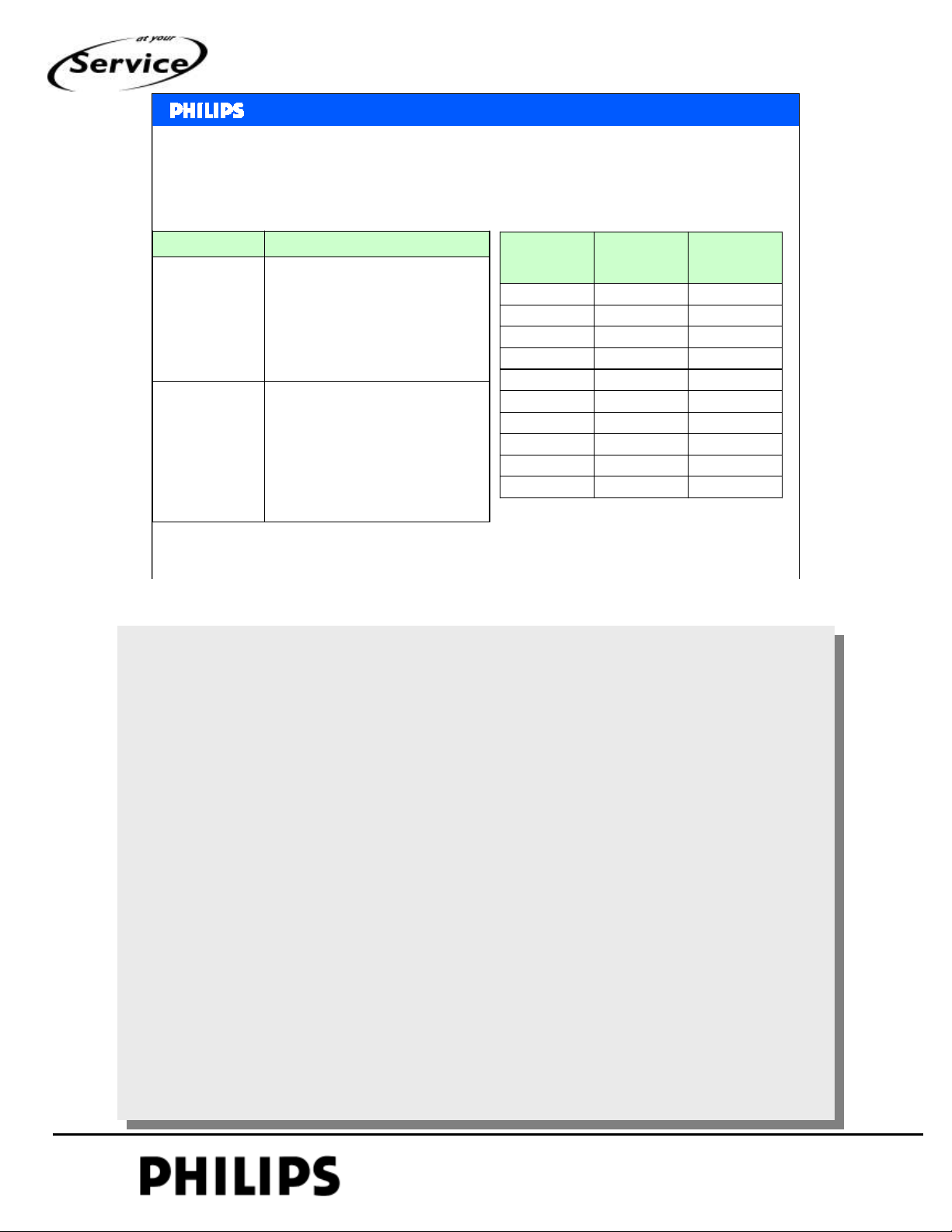
Supported format (YPbPr)Supported HDMI format
640x480 @60Hz, 72Hz, 75Hz, 85Hz
800x600 @ 60Hz, 72Hz, 75Hz, 85Hz
PC Format
Video Format
Philips CE Europe, Euroservice, March 2007
1024x768 @60Hz, 70Hz, 75Hz, 85Hz
720(1440) x 480i @60Hz,
720(1440) x 576i @50Hz,
1920 x 1080i@50Hz, 60Hz
1920x 1080p@50Hz, 60Hz
Signal FormatMode
720x400 @70Hz
1280x768 @60Hz
1280x1024@60Hz
1360x768 @60Hz
720 x 480p @60Hz
720 x 576p @50Hz,
1280 x 720p @ 60Hz,
1280 x 720p @50Hz
Signal
Format
Horizontal
Frequency
(kHz)
Introduction chapter 1, Slide 16
Vertical
Frequency
(Hz)
59.9415.734480i
6031.500480P
5015.625576i
5031.250576P
5037.500720P
6045.000720P
5028.1251080i
6033.751080i
50Hz56.251080P
60Hz67.51080P
PERSONAL NOTES:
PERSONAL NOTES:
© Copyright reserved 2002 Philips Consumer Electronics Euroservice
<< introduction >>
chapter: 1 page: 16
Page 17
<< introduction >>
<< introduction >>
SERVICE TRAINING
PERSONAL NOTES:
PERSONAL NOTES:
© Copyright reserved 2002 Philips Consumer Electronics Euroservice
<< introduction >>
chapter: 1 page: 17
Page 18
<< mechanical and
<< mechanical and
blockdiagrams
blockdiagrams
Chapter 2 Mechanical and block diagrams
Hans Munsters
Philips CE / Euroservice
>>
>>
SERVICE TRAINING
March 2007
PERSONAL NOTES:
PERSONAL NOTES:
© Copyright reserved 2002 Philips Consumer Electronics Euroservice
<< mechanical and blockdigrams >>
chapter: 2 page: 1
Page 19
<< mechanical and
<< mechanical and
blockdiagrams
blockdiagrams
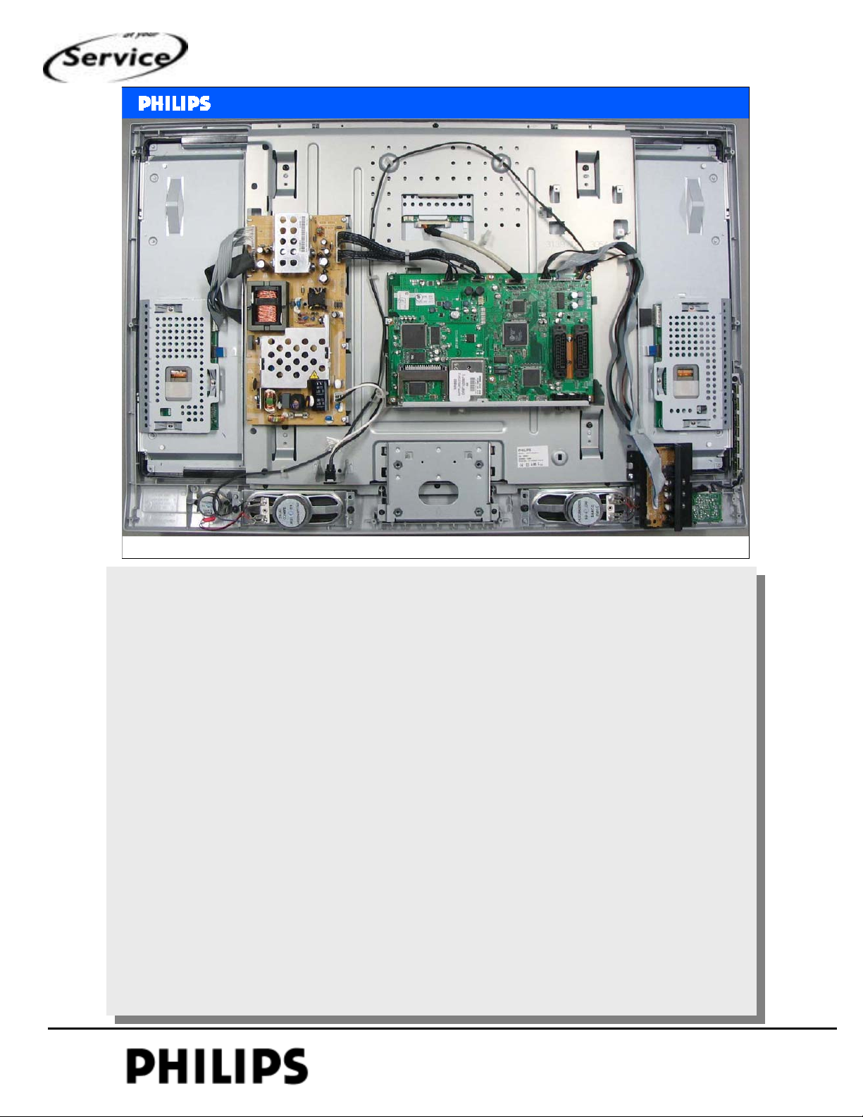
Wiring of 32PFL5522D
>>
>>
SERVICE TRAINING
Philips CE Europe, Euroservice, March 2007
Picture of 32” LCD set.
In the middle the SSB without screening.
On the left side of SSB there is the power supply.
Right bottom side front input and local keyboard.
Mechanical and blockdiagram, chapter: 2, Slide 2
PERSONAL NOTES:
PERSONAL NOTES:
© Copyright reserved 2002 Philips Consumer Electronics Euroservice
<< mechanical and blockdigrams >>
chapter: 2 page: 2
Page 20
<< mechanical and
<< mechanical and
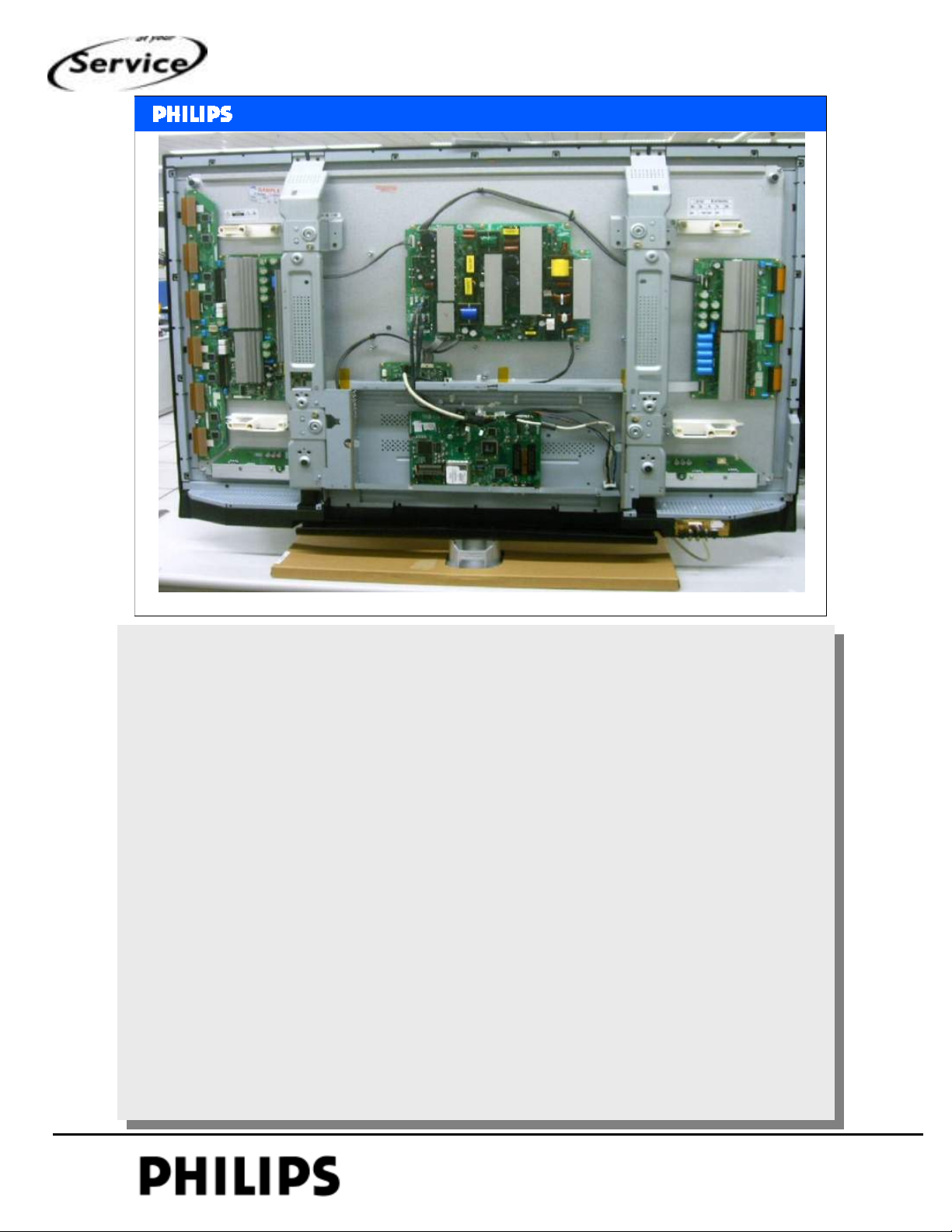
Rear side of 42” PDP-set
blockdiagrams
blockdiagrams
>>
>>
SERVICE TRAINING
Philips CE Europe, Euroservice, March 2007
Example of a plasma set with SDI display.
In the middle again the SSB.
If the rear cover is removed, there is direct access to the SSB.
There is no top screening.
Mechanical and blockdiagram, chapter: 2, Slide 3
PERSONAL NOTES:
PERSONAL NOTES:
© Copyright reserved 2002 Philips Consumer Electronics Euroservice
<< mechanical and blockdigrams >>
chapter: 2 page: 3
Page 21
<< mechanical and
<< mechanical and
Dual LVDS out to
display
blockdiagrams
blockdiagrams
1080P module
12V supply
>>
>>
SERVICE TRAINING
Single LVDS
Philips CE Europe, Euroservice, March 2007
LVDS input from SSB, via 1080P board up scaled.
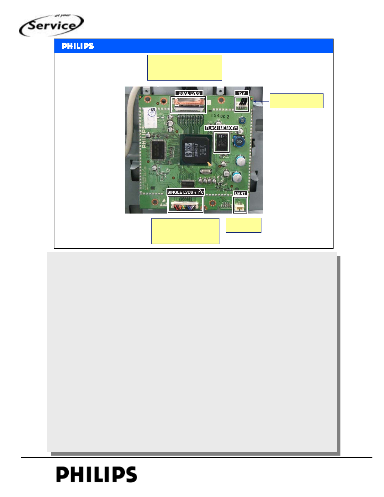
LVDS out to display is dual LVDS output, which is able to drive full-HD panel.
The module needs 12V supply voltage and I2C control from SSB.
UART can be used for software upgrading of this module.
JTAG is debug connector used by development.
from SSB
UART
Mechanical and blockdiagram, chapter: 2, Slide 4
PERSONAL NOTES:
PERSONAL NOTES:
© Copyright reserved 2002 Philips Consumer Electronics Euroservice
<< mechanical and blockdigrams >>
chapter: 2 page: 4
Page 22
<< mechanical and
<< mechanical and
blockdiagrams
blockdiagrams
Component side SSB
>>
>>
SERVICE TRAINING
Philips CE Europe, Euroservice, March 2007
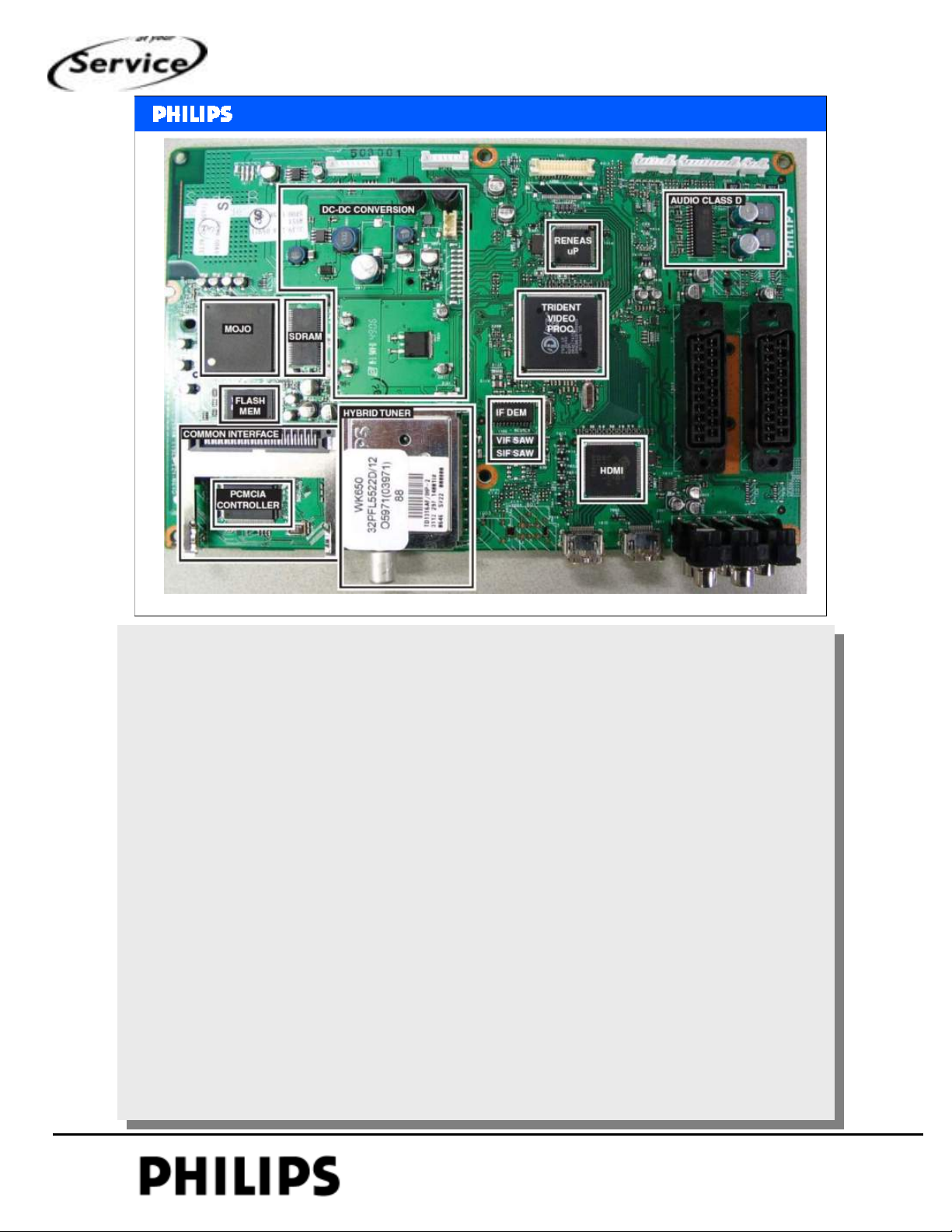
Top side of the SSB with indication of the key components.
In the middle there is the Trident video processor.
Above it the Renesas uP.
Right top there is the audio amplifier.
The left part of the SSB is for digital reception. In LC4 this was the IBO-part, this is now
integrated on board.
The same chipset for digital is used (MOJO).
Between digital and Trident there is the DC-DC conversion.
Mechanical and blockdiagram, chapter: 2, Slide 5
PERSONAL NOTES:
PERSONAL NOTES:
© Copyright reserved 2002 Philips Consumer Electronics Euroservice
<< mechanical and blockdigrams >>
chapter: 2 page: 5
Page 23
<< mechanical and
<< mechanical and
blockdiagrams
blockdiagrams
Solder side
>>
>>
SERVICE TRAINING
Philips CE Europe, Euroservice, March 2007
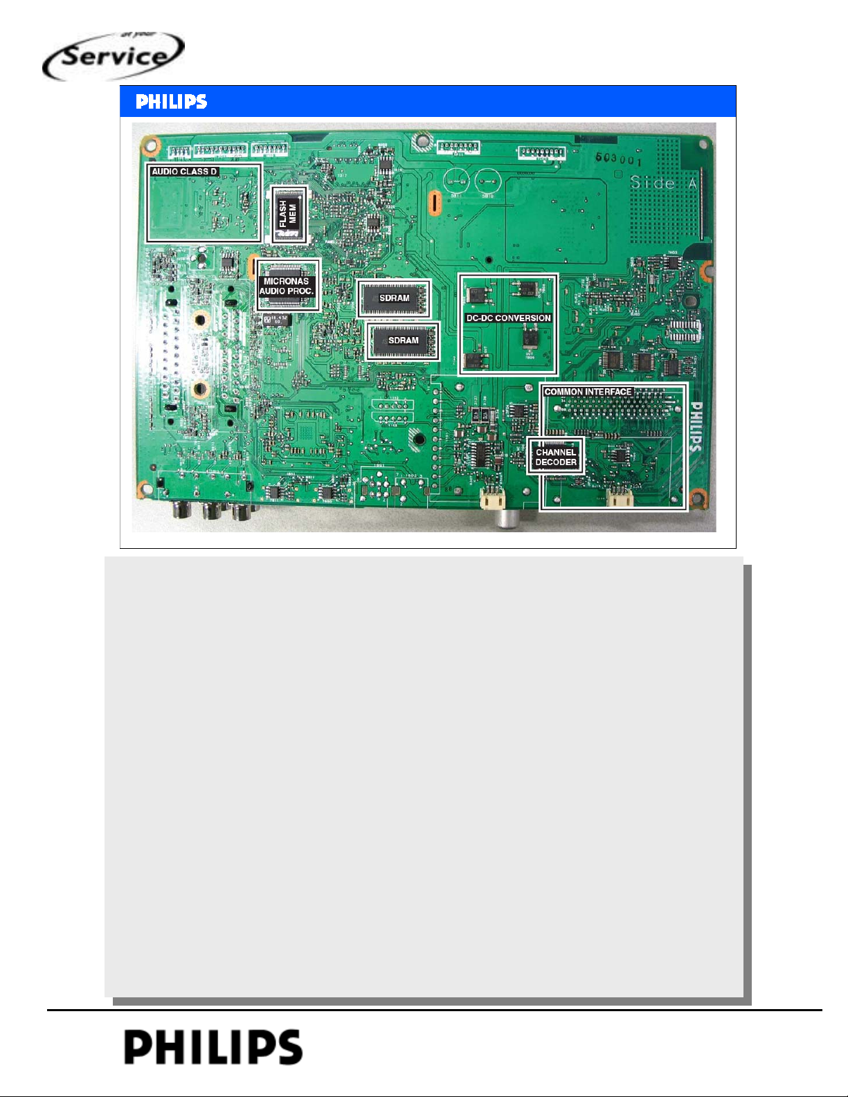
Copper side.
Flash MEM in this chip is the software of the set.
Micronas is the audio demodulator.
2x SDRAM is the for the video processor
Right hand side there is again the digital part.
Common Interface is indicated (PCMCIA connector)
The channel decoder is on this side.
2 connectors for Compair.
At the tuner for I2C communication with the Renesas uP (upgrade main SW)
At the digital part UART communcation with MOJO
Mechanical and blockdiagram, chapter: 2, Slide 6
PERSONAL NOTES:
PERSONAL NOTES:
© Copyright reserved 2002 Philips Consumer Electronics Euroservice
<< mechanical and blockdigrams >>
chapter: 2 page: 6
Page 24
<< mechanical and
<< mechanical and
blockdiagrams
blockdiagrams
block diagrams
>>
>>
SERVICE TRAINING
Philips CE Europe, Euroservice, March 2007
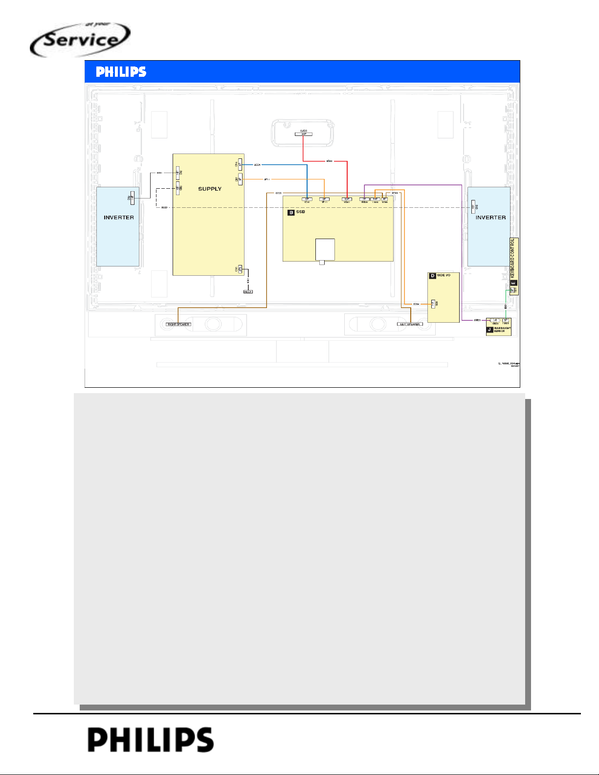
Wiring diagram for the (32 inch) LCD-set.
From power supply 2 cables to the inverters.
With EEFL (External Electrode Fluorescent Light) there are 2 small inverters.
LVDS cable pos.nr. 8G51
Mechanical and blockdiagram, chapter: 2, Slide 7
PERSONAL NOTES:
PERSONAL NOTES:
© Copyright reserved 2002 Philips Consumer Electronics Euroservice
<< mechanical and blockdigrams >>
chapter: 2 page: 7
Page 25
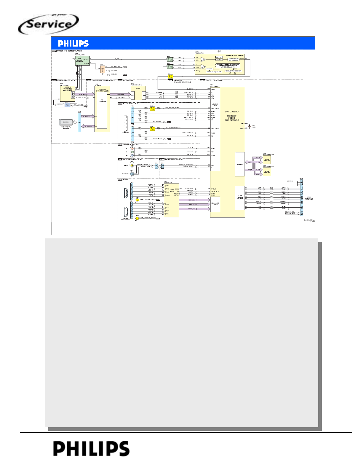
<< mechanical and
<< mechanical and
blockdiagrams
blockdiagrams
Block diagram video
>>
>>
SERVICE TRAINING
Philips CE Europe, Euroservice, March 2007
Block diagram video.
From tuner to IF-demodulator (VIF and SIF), output from IC7113 is CVBS.
All video inputs go to the Trident, also from IBO-part.
2 scart connectors and you can see at which pins are the signals.
For the 2 HDMI there is a HDMI-receiver used (in this chip are also the HDCP-keys).
Output from this chip is digital to the Trident
The Trident chip does the complete video processing (I/O switching, multi standard colour
decoding, txt decoder and LVDS output).
At the LVDS output is also Vdisp (5V or 12V depending which display is used).
There is also indicated I2C (this is only used for FHP-panel)
Mechanical and blockdiagram, chapter: 2, Slide 8
PERSONAL NOTES:
PERSONAL NOTES:
© Copyright reserved 2002 Philips Consumer Electronics Euroservice
<< mechanical and blockdigrams >>
chapter: 2 page: 8
Page 26
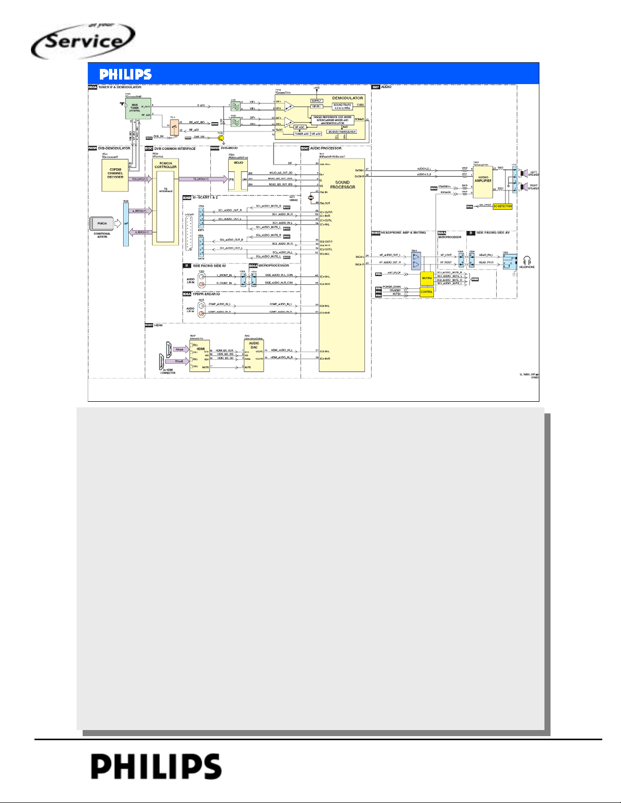
<< mechanical and
<< mechanical and
blockdiagrams
blockdiagrams
Block diagram audio
>>
>>
SERVICE TRAINING
Philips CE Europe, Euroservice, March 2007
Block diagram audio.
Also here from tuner to the same IF-demodulator.
Audio output pin 12 is sound-IF (FM modulated signal), this is fed to the audio processor
MSP4450.
Audio from IBO is processed by the MOJO and the output is I2S format (clock, data and
word select).
At the bottom is again HDMI. The audio from the HDMI source is converted from I2S
format to analogue.
Via this way to the pins 57 and 58 of IC7411.
There are 2 outputs from the audio-IC:
Pins 26,27 via the amplifier to the speakers
Pins 23,24 for the headphone output
Mechanical and blockdiagram, chapter: 2, Slide 9
PERSONAL NOTES:
PERSONAL NOTES:
© Copyright reserved 2002 Philips Consumer Electronics Euroservice
<< mechanical and blockdigrams >>
chapter: 2 page: 9
Page 27
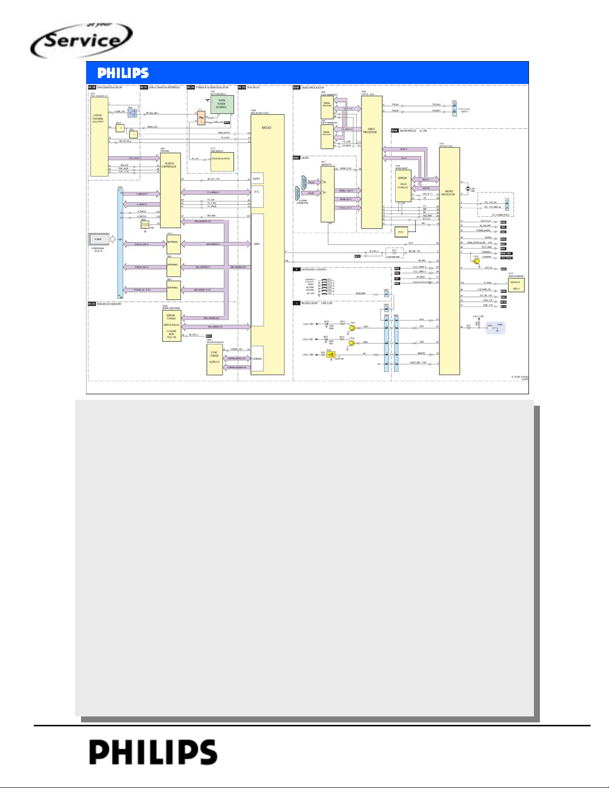
<< mechanical and
<< mechanical and
Block diagram control & clock
blockdiagrams
blockdiagrams
>>
>>
SERVICE TRAINING
Philips CE Europe, Euroservice, March 2007
On the right side there is the micro processor.
The uP is supplied with 3V3 and on pin 10 is the POR (reset is made with 7312).
Connected to the uP is IC7315, the nvm where all analogue settings are stored (also
option codes, alignments)
At pin 25 is SDM (service default mode)
There are 2 standby lines: STANDBY and STANDBYn
STANDBYn to audio amplifier (and optional to PDP (FHP only))
SATNDBY to supply and for muting audio
Communication between RENESAS and TRIDENT via parallel bus.
The MOJO (DVB-T part) is addressed via I2C from RENESAS.
The communication on DVB-T is via MOJO.
Mechanical and blockdiagram, chapter: 2, Slide 10
PERSONAL NOTES:
PERSONAL NOTES:
© Copyright reserved 2002 Philips Consumer Electronics Euroservice
<< mechanical and blockdigrams >>
chapter: 2 page: 10
Page 28
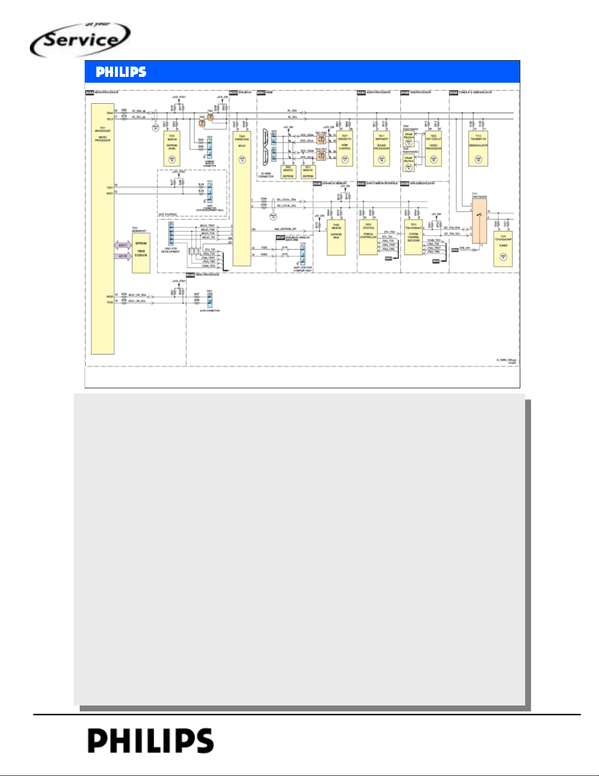
<< mechanical and
<< mechanical and
blockdiagrams
blockdiagrams
I2C overview
>>
>>
SERVICE TRAINING
Philips CE Europe, Euroservice, March 2007
On the left side is the RENESAS uP. This is the master that controls the set.
Nvm (7315) is connected to the uP, if set is in standby 7320 and 7321 will block to save power consumption.
Connector 1314 is for connection with Compair and 1311 is UART connector only used by development.
At the MOJO is UART connector for communication with Compair.
I2C local is the internal I2C bus for the DVB-T circuitry.
Also connected here another nvm (7H03) for DVB-T part.
2 more nvm’s for HDMI input, in these nvm is the EDID (Extended Display Identification Data).
On the same I2C bus are the other tv-IC’s.
There is indication about error codes. In this way there is a quick indication which circuitry has to be
checked.
The tuner can be addressed from COFDM (IC7F01) Æ digital mode
or from Renesas in analogue mode.
1G51 is the LVDS connector, I2C is used with FHP displays.
Mechanical and blockdiagram, chapter: 2, Slide 11
PERSONAL NOTES:
PERSONAL NOTES:
© Copyright reserved 2002 Philips Consumer Electronics Euroservice
<< mechanical and blockdigrams >>
chapter: 2 page: 11
Page 29
<< mechanical and
<< mechanical and
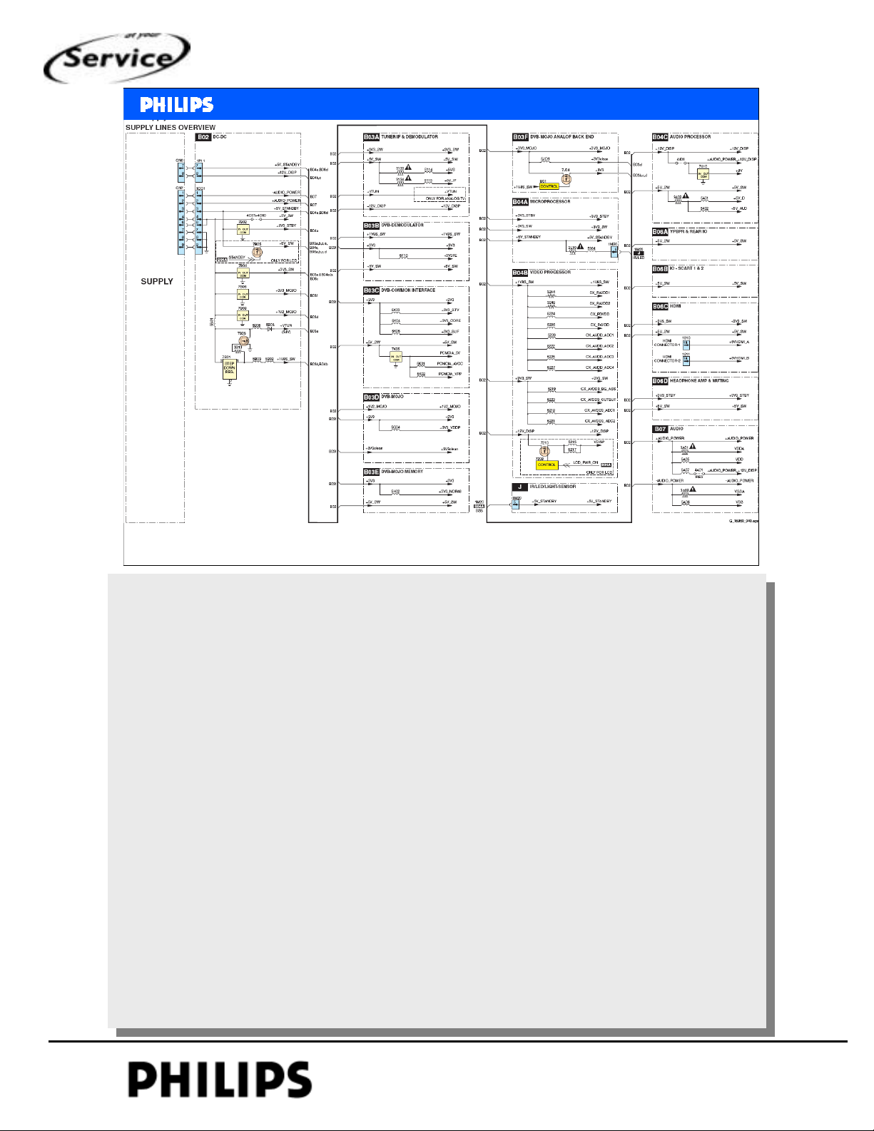
Overview of supply lines
blockdiagrams
blockdiagrams
>>
>>
SERVICE TRAINING
Philips CE Europe, Euroservice, March 2007
On left side the power supply
Mechanical and blockdiagram, chapter: 2, Slide 12
PERSONAL NOTES:
PERSONAL NOTES:
© Copyright reserved 2002 Philips Consumer Electronics Euroservice
<< mechanical and blockdigrams >>
chapter: 2 page: 12
Page 30
<< mechanical and
<< mechanical and
blockdiagrams
blockdiagrams
>>
>>
SERVICE TRAINING
PERSONAL NOTES:
PERSONAL NOTES:
© Copyright reserved 2002 Philips Consumer Electronics Euroservice
<< mechanical and blockdigrams >>
chapter: 2 page: 13
Page 31
<< Power Supply>>
<< Power Supply>>
Chapter 3 Power supply
Hans Munsters
Philips CE / Euroservice
SERVICE TRAINING
March 2007
PERSONAL NOTES:
PERSONAL NOTES:
© Copyright reserved 2002 Philips Consumer Electronics Euroservice
<< power supply >>
chapter: 3 page: 1
Page 32
<< Power Supply>>
<< Power Supply>>
OVERVIEW (26” TO 47” LCD)
SERVICE TRAINING
Inverter
(Master)
Philips CE Europe, Euroservice, March 2007
LC07 SSB
PSU
AC
Inlet
Bolt-on
Inverter
(Slave)
< Power Supply >, chapter: 3, Slide 2
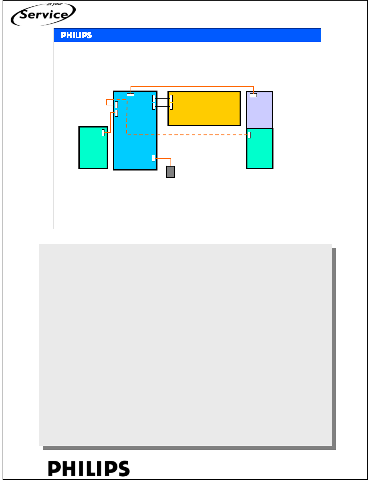
The power supply is board swap (no diagrams available).
The PSU powers the SSB, inverter (LCD backlight) and bolt-on module.
2 inverters are indicted (master,slave).
PERSONAL NOTES:
PERSONAL NOTES:
© Copyright reserved 2002 Philips Consumer Electronics Euroservice
<< power supply >>
chapter: 3 page: 2
Page 33
<< Power Supply>>
312242724571
(
)
<< Power Supply>>
LCD PSU DIVERSITY
SERVICE TRAINING
Screen
26" & 32" LCD
37" & 42" LCD
47" LCD
42" PDP 996500045386 SDI Global 90 ~ 265
50" PDP Global 90 ~ 265
Philips CE Europe, Euroservice, March 2007
Screen
Type
12 nc Region
313912878521
(DELTA)
312242724431
(PPS)
313912878451
(DELTA)
312242724521
(PPS)
PPS
313912878921
(DELTA)
Europe 198 ~ 265
Global 90 ~ 265
Global 90 ~ 265
Global 90 ~ 265
Operating
Voltage Range
< Power Supply >, chapter: 3, Slide 3
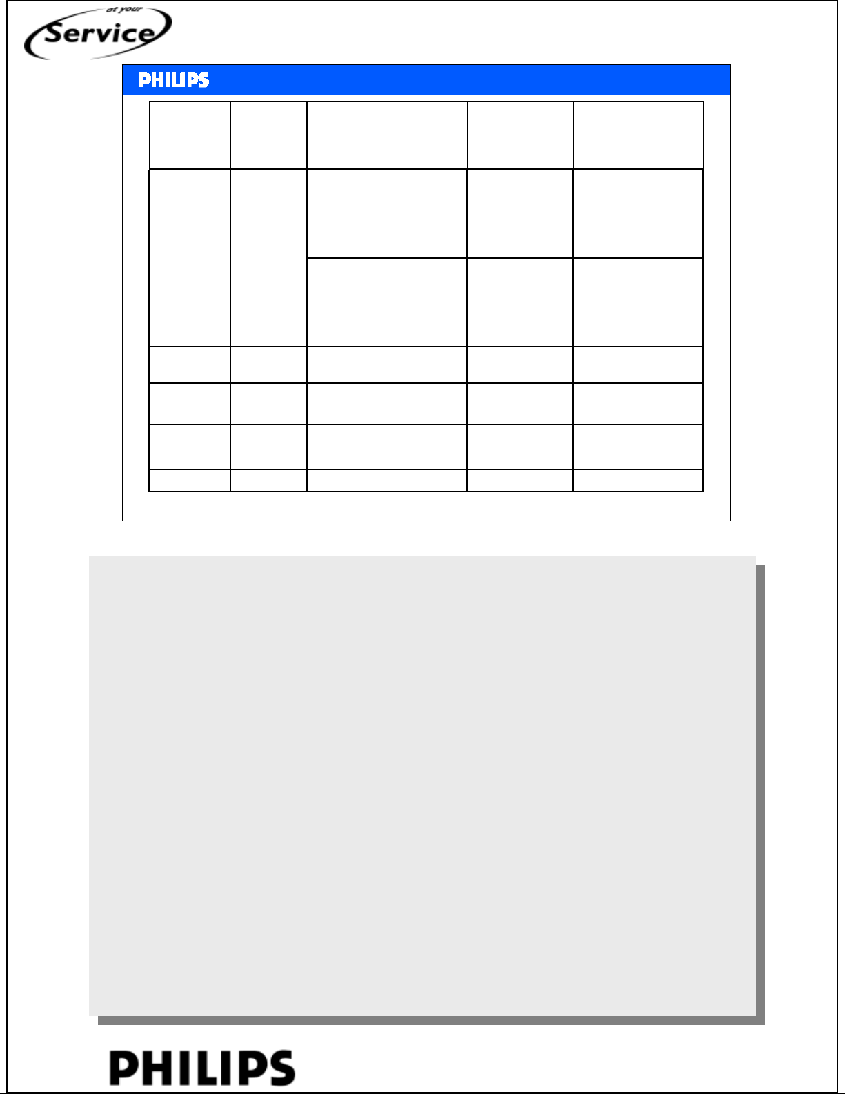
Overview of used power supplies (LCD and plasma).
PERSONAL NOTES:
PERSONAL NOTES:
© Copyright reserved 2002 Philips Consumer Electronics Euroservice
<< power supply >>
chapter: 3 page: 3
Page 34
Connectors
To Inverter
<< Power Supply>>
<< Power Supply>>
26” / 32” PSU (DELTA)
Connectors
To Bolt-on
Module
Connectors
to LC07 SSB
SERVICE TRAINING
LLC
Philips CE Europe, Euroservice, March 2007
Delta is one the used suppliers.
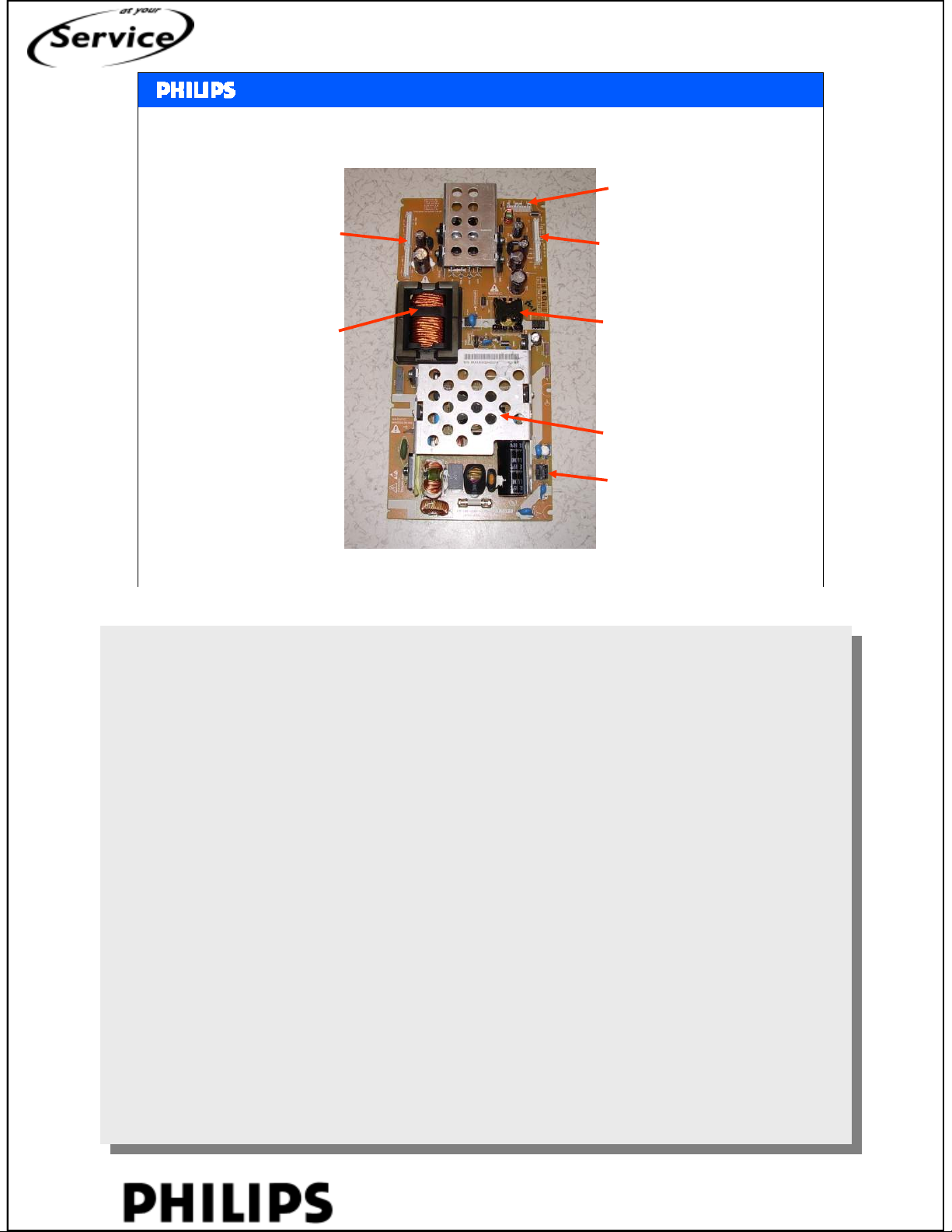
Here is indication what is on the power supply.
Flyback
PFC
AC Input
Connector
< Power Supply >, chapter: 3, Slide 4
PERSONAL NOTES:
PERSONAL NOTES:
© Copyright reserved 2002 Philips Consumer Electronics Euroservice
<< power supply >>
chapter: 3 page: 4
Page 35
<< Power Supply>>
<< Power Supply>>
37” / 42” PSU (PPS)
SERVICE TRAINING
Connectors
To Bolt-on
Module
Flyback
PFC
Philips CE Europe, Euroservice, March 2007
Connectors
to LC07 SSB
Connectors
To Inverter
LLC
AC Input
Connector
< Power Supply >, chapter: 3, Slide 5
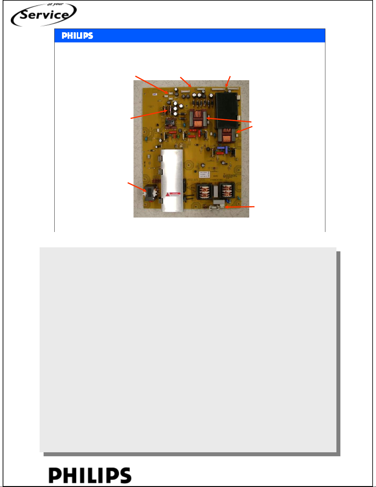
Picture of the power supply for big LCD-sets.
This supply is from Philips Power Solutions (PPS).
PERSONAL NOTES:
PERSONAL NOTES:
© Copyright reserved 2002 Philips Consumer Electronics Euroservice
<< power supply >>
chapter: 3 page: 5
Page 36
<< Power Supply>>
<< Power Supply>>
47” PSU (DELTA)
SERVICE TRAINING
Connectors
To Inverter
LLC
PFC
Philips CE Europe, Euroservice, March 2007
Connectors
To Bolt-on
Module
Connectors
to LC07 SSB
Flyback
AC Input
Connector
< Power Supply >, chapter: 3, Slide 6
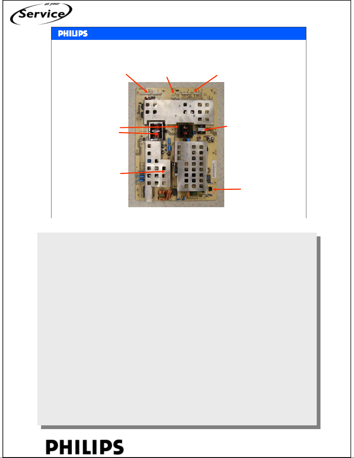
Power supply for 47” LCD-set.
PERSONAL NOTES:
PERSONAL NOTES:
© Copyright reserved 2002 Philips Consumer Electronics Euroservice
<< power supply >>
chapter: 3 page: 6
Page 37
<< Power Supply>>
<< Power Supply>>
B02 – DC DC CONVERTER BLOCK DIAGRAM
7B02
7B05
7B01
7B03
7B04
7B06
SERVICE TRAINING
Philips CE Europe, Euroservice, March 2007
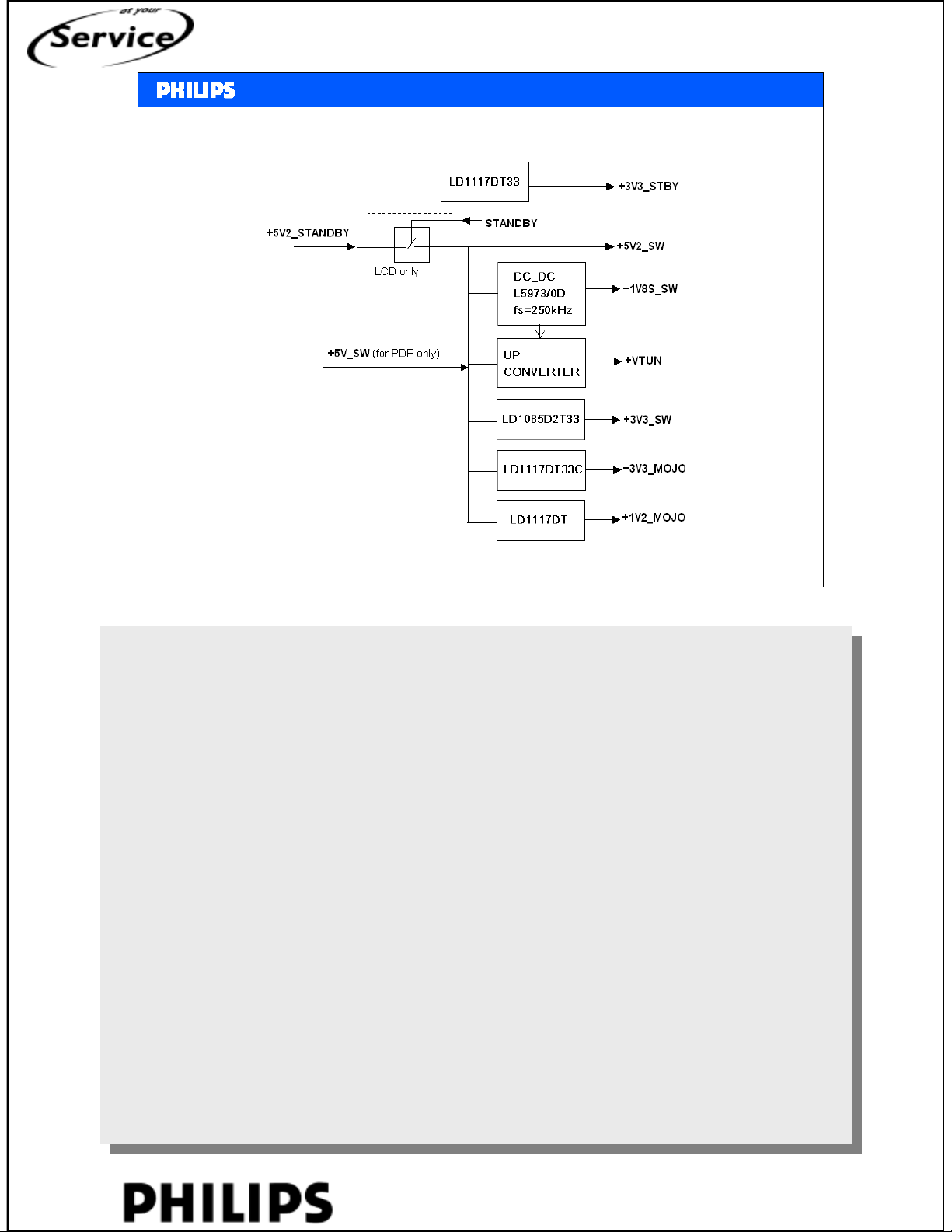
Power supply part on the SSB.
Input is 5V, from this various voltages are derived.
5V standby is always present (also in off-mode).
7B08
< Power Supply >, chapter: 3, Slide 7
PERSONAL NOTES:
PERSONAL NOTES:
© Copyright reserved 2002 Philips Consumer Electronics Euroservice
<< power supply >>
chapter: 3 page: 7
Page 38
<< Power Supply>>
<< Power Supply>>
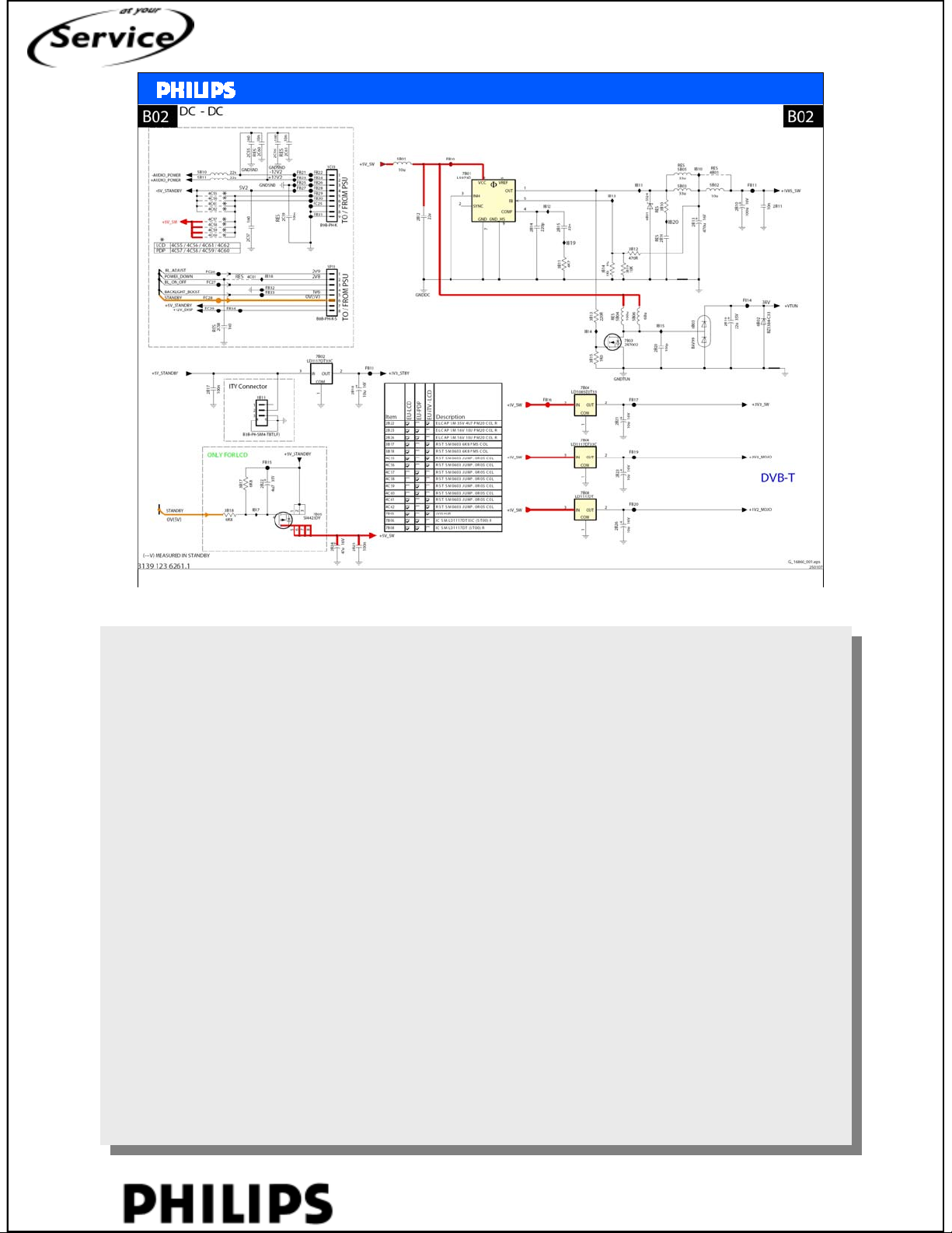
Diagram B02 DC-DC converter
SERVICE TRAINING
Philips CE Europe, Euroservice, March 2007
2 connectors to the power supply (1C01 and 1P11).
1-1P11 backlight dimming
3-1P11 backlight on/off
5-1P11 backlight boost (not used in LC7)
6-1P11 is the standby line
From the 5V_SW 1,8V and Vtun is made.
IC7B01 is serial switch mode, at pin 1 is block wave. This block is also used to drive
FET 7B03 to make the Vtun (33V).
< Power Supply >, chapter: 3, Slide 8
PERSONAL NOTES:
PERSONAL NOTES:
© Copyright reserved 2002 Philips Consumer Electronics Euroservice
<< power supply >>
chapter: 3 page: 8
Page 39
<< Power Supply>>
<< Power Supply>>
SERVICE TRAINING
PERSONAL NOTES:
PERSONAL NOTES:
© Copyright reserved 2002 Philips Consumer Electronics Euroservice
<< power supply >>
chapter: 3 page: 9
Page 40
Chapter 9 Service modes
Hans Munsters
Philips CE / Euroservice
March 2007
<< Service mode >>
<< Service mode >>
SERVICE TRAINING
PERSONAL NOTES:
PERSONAL NOTES:
© Copyright reserved 2002 Philips Consumer Electronics Euroservice
<< Service mode >>
chapter: 09 page: 1
Page 41
<< Service mode >>
<< Service mode >>
Software Clustering:
Analogue LCD - LC71EL1_vX.XX
Analogue PDP - LC71EP1_vX.XX
Digital LCD - LC72EL1_vX.XX
Digital PDP - LC72EP1_vX.XX
Digital LCD - LC72ELH_vX.XX 1080p display
where X.XX denotes the software version
SERVICE TRAINING
Philips CE Europe, Euroservice, March 2007
<service modes>, chapter: 9, Slide 2
PERSONAL NOTES:
PERSONAL NOTES:
© Copyright reserved 2002 Philips Consumer Electronics Euroservice
<< Service mode >>
chapter: 09 page: 2
Page 42
Panel Diversity
Philips CE Europe, Euroservice, March 2007
<< Service mode >>
<< Service mode >>
NVM Option Code
Panel TypeSourceScreenPanel ID
Panel_242" LCD11
Panel_142" PDP HD16
Panel_242" PDP HD17
Panel_318
(Location 400 Dec)
045LPL : LC260W-SLB2Panel_126" LCD1
067AUO : T260XW02 V7Panel_226" LCD2
068CMO : V260B1Panel_326" LCD3
046LPL : LC320W01-SL06Panel_132" LCD4
050AUO : T315X02VDPanel_232" LCD5
069CMO : V315B1Panel_332" LCD6
071LPL : LC370WX1-SLB1Panel_137" LCD7
072AUO : T370XW02 V5Panel_237" LCD8
-ReservedPanel_39
073LPL : LC420WX3-SLA1Panel_142" LCD10
076AUO : T420XW01 V5
-ReservedPanel_342" LCD12
075LPL : LC470WU2-SLA1Panel_147" LCD 1080P13
082T470HW01 V0Panel_247" LCD 1080P14
-ReservedPanel_315
083SDI : HD W2
084LG : HD X4
-Reserved
085SDI : HD W2Panel_150" PDP HD19
086LG : HD X4Panel_250" PDP HD20
-ReservedPanel_321
Address 400 there can
be checked which display
is programmed
<service modes>, chapter: 9, Slide 3
SERVICE TRAINING
PERSONAL NOTES:
PERSONAL NOTES:
© Copyright reserved 2002 Philips Consumer Electronics Euroservice
<< Service mode >>
chapter: 09 page: 3
Page 43
SDM mode:
To Enter: 062596 menu
To Exit: standby
SAM mode:
To Enter: 0 6 2 5 9 6 follow by i+
To Exit: standby
CSM mode:
To Enter: Using RC to key in 1 2 3 6 5 4
To Exit: Press Menu on RC
<< Service mode >>
<< Service mode >>
Service modes
SERVICE TRAINING
Display code 062598 menu xxx
Philips CE Europe, Euroservice, March 2007
<service modes>, chapter: 9, Slide 4
PERSONAL NOTES:
PERSONAL NOTES:
© Copyright reserved 2002 Philips Consumer Electronics Euroservice
<< Service mode >>
chapter: 09 page: 4
Page 44
<< Service mode >>
<< Service mode >>
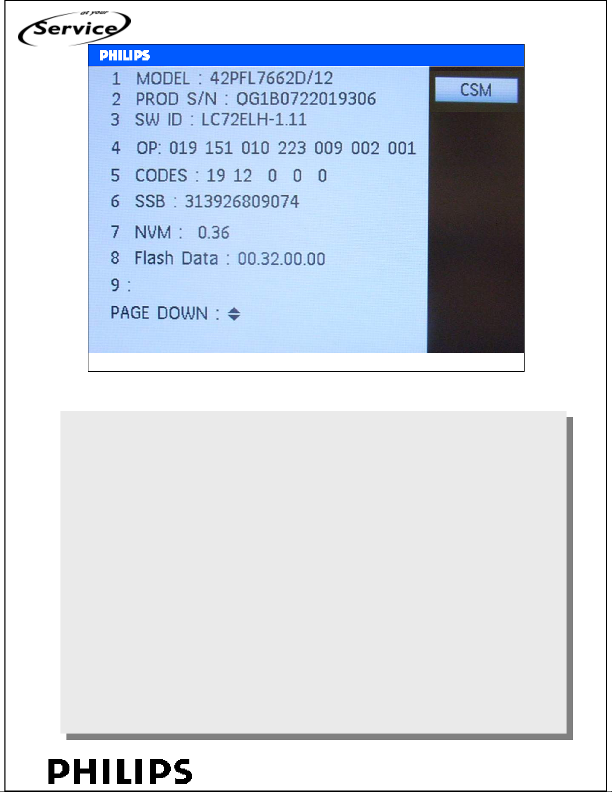
Customer Service Mode page 1
SERVICE TRAINING
Philips CE Europe, Euroservice, March 2007
1. MODEL. Type number, e.g. 42PFL7662/12. (*)
1. MODEL. Type number, e.g. 42PFL7662/12. (*)
2. PROD S/N. Product serial no., e.g. QG1B0722019306. (*)
2. PROD S/N. Product serial no., e.g. QG1B0722019306. (*)
3. SW ID. Software cluster and version is displayed.
3. SW ID. Software cluster and version is displayed.
4. OP. Option code information.
4. OP. Option code information.
5. CODES. Error buffer contents.
5. CODES. Error buffer contents.
6. SSB. Indication of the SSB order code (12nc). (*)
6. SSB. Indication of the SSB order code (12nc). (*)
7. NVM. The NVM software version no.
7. NVM. The NVM software version no.
8. Flash Data. PQ (picture quality) and AQ (audio quality)
8. Flash Data. PQ (picture quality) and AQ (audio quality)
data version. This is a sub set of the main SW.
data version. This is a sub set of the main SW.
9. Reserved for display 12nc.
9. Reserved for display 12nc.
<service modes>, chapter: 9, Slide 5
PERSONAL NOTES:
PERSONAL NOTES:
© Copyright reserved 2002 Philips Consumer Electronics Euroservice
<< Service mode >>
chapter: 09 page: 5
Page 45
<< Service mode >>
<< Service mode >>
Customer Service Mode page 2
SERVICE TRAINING
Philips CE Europe, Euroservice, March 2007
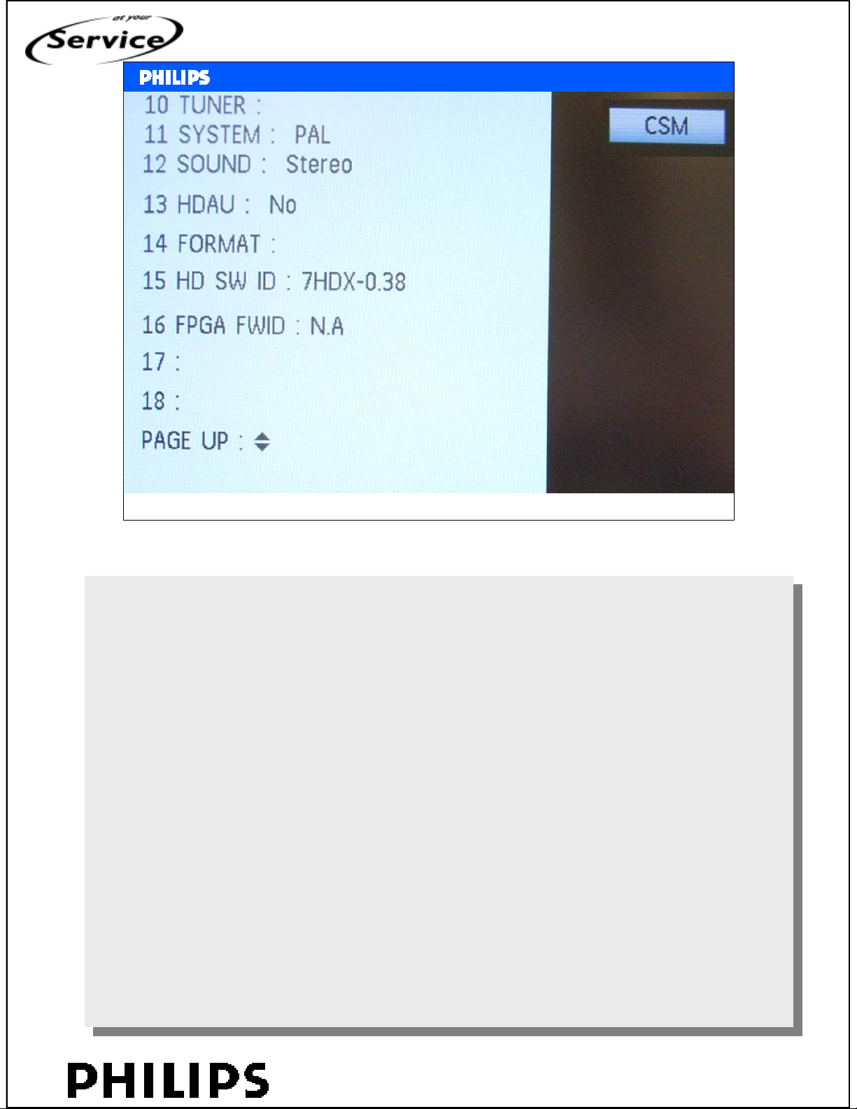
10. TUNER. Indicates the tuner signal condition: “Weak” when
10. TUNER. Indicates the tuner signal condition: “Weak” when
signal falls below threshold value, “Medium” when signal is
signal falls below threshold value, “Medium” when signal is
at mid-range, and “Strong” when signal falls above
at mid-range, and “Strong” when signal falls above
threshold value.
threshold value.
11. SYSTEM. Gives information about the video system of the
11. SYSTEM. Gives information about the video system of the
selected transmitter (PAL/SECAM/NTSC).
selected transmitter (PAL/SECAM/NTSC).
12. SOUND. Gives information about the audio system of the
12. SOUND. Gives information about the audio system of the
selected transmitter (MONO/STEREO/NICAM).
selected transmitter (MONO/STEREO/NICAM).
13. HDAU. HDMI audio stream detection. “YES” means audio
13. HDAU. HDMI audio stream detection. “YES” means audio
stream detected. “NO” means no audio stream present.
stream detected. “NO” means no audio stream present.
Only displayed when HDMI source is selected.
Only displayed when HDMI source is selected.
14. FORMAT. Gives information about the video format of the
14. FORMAT. Gives information about the video format of the
selected transmitter (480i/480p/720p/1080i50, 1080p30,….).
selected transmitter (480i/480p/720p/1080i50, 1080p30,….).
15. HD SW ID. Software version of the 1080p full HD module
15. HD SW ID. Software version of the 1080p full HD module
(when present).
(when present).
16. FPGA FWID. Software for ambilight software
16. FPGA FWID. Software for ambilight software
<service modes>, chapter: 9, Slide 6
PERSONAL NOTES:
PERSONAL NOTES:
© Copyright reserved 2002 Philips Consumer Electronics Euroservice
<< Service mode >>
chapter: 09 page: 6
Page 46
<< Service mode >>
<< Service mode >>
Service Default Mode
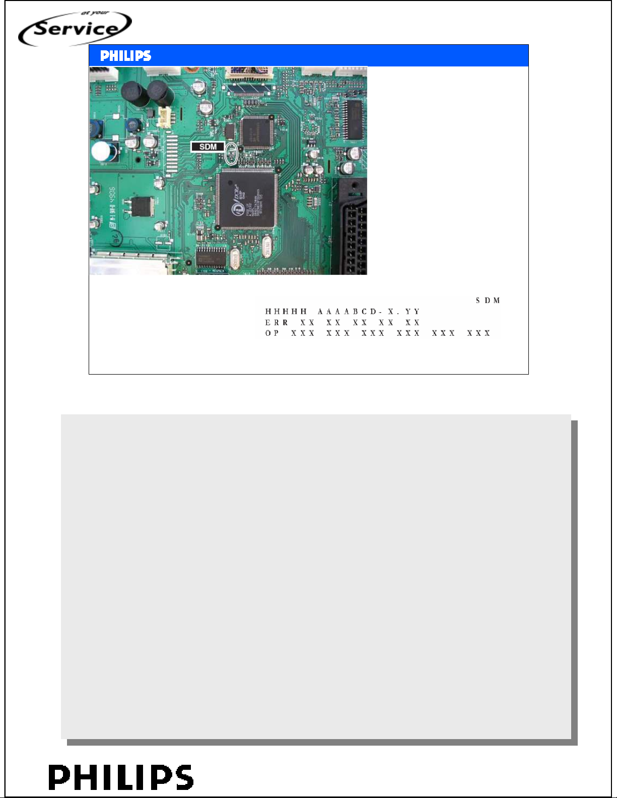
If the 2 contacts for
SDM are shortened
at start up, then SDM
is activated
Or:
062596 menu
SERVICE TRAINING
Philips CE Europe, Euroservice, March 2007
Short one of the “Service” jumpers on the TV board during
Short one of the “Service” jumpers on the TV board during
cold start. Then press the mains button (remove the short after start-up). Caution:
cold start. Then press the mains button (remove the short after start-up). Caution:
Activating SDM by shorting “Service” jumpers will override
Activating SDM by shorting “Service” jumpers will override
the DC speaker protection (error 1), the General I2C error
the DC speaker protection (error 1), the General I2C error
(error 4), and the Trident video processor error (error 5).
(error 4), and the Trident video processor error (error 5).
When doing this, the service-technician must know exactly
When doing this, the service-technician must know exactly
what he is doing, as it could damage the television set.
what he is doing, as it could damage the television set.
<service modes>, chapter: 9, Slide 7
PERSONAL NOTES:
PERSONAL NOTES:
© Copyright reserved 2002 Philips Consumer Electronics Euroservice
<< Service mode >>
chapter: 09 page: 7
Page 47
<< Service mode >>
<< Service mode >>
Service Alignment Mode
SERVICE TRAINING
Philips CE Europe, Euroservice, March 2007
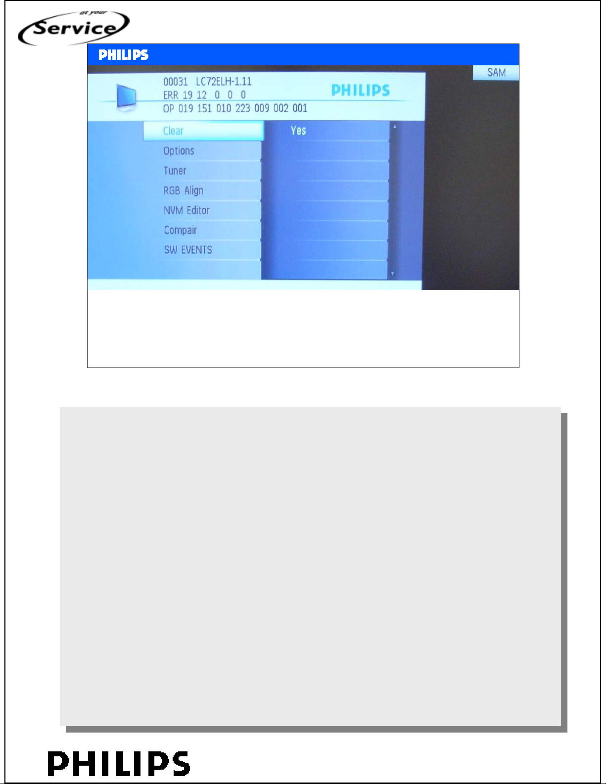
1. 00031. This represents the run timer. The run timer counts normal operation hours, but does
1. 00031. This represents the run timer. The run timer counts normal operation hours, but does
not count Stand-by hours.
not count Stand-by hours.
2. LC72ELHH-1.11. Software Identification, Version, and Cluster for the SW name definition.
2. LC72ELHH-1.11. Software Identification, Version, and Cluster for the SW name definition.
3. SAM. Indication of the Service Alignment Mode.
3. SAM. Indication of the Service Alignment Mode.
4. ERR (ERRor buffer). Shows all errors detected since the last time the buffer was erased. Five
4. ERR (ERRor buffer). Shows all errors detected since the last time the buffer was erased. Five
errors possible.
errors possible.
5. OP (Option Bytes). Used to read-out the option bytes.
5. OP (Option Bytes). Used to read-out the option bytes.
6. Clear. Erases the contents of the error buffer. Select the CLEAR menu item and press the
6. Clear. Erases the contents of the error buffer. Select the CLEAR menu item and press the
MENU RIGHT key. The content of the error buffer is cleared.
MENU RIGHT key. The content of the error buffer is cleared.
7. Options. Used to set the option bits.
7. Options. Used to set the option bits.
8. Tuner. Used to align the tuner.
8. Tuner. Used to align the tuner.
9. RGB Align. Used to align the White Tone.
9. RGB Align. Used to align the White Tone.
10. NVM Editor. Can be used to change the NVM data in the television set.
10. NVM Editor. Can be used to change the NVM data in the television set.
11. ComPair. Can be used to switch the television to “In Application Programming” mode (IAP),
11. ComPair. Can be used to switch the television to “In Application Programming” mode (IAP),
for software uploading via ComPair. Caution: When this mode is selected without ComPair
for software uploading via ComPair. Caution: When this mode is selected without ComPair
connected, the TV will be blocked.
connected, the TV will be blocked.
12. SW Events. Not useful for Service. This can be used by development to monitor SW
12. SW Events. Not useful for Service. This can be used by development to monitor SW
behaviour during stress test.
behaviour during stress test.
<service modes>, chapter: 9, Slide 8
PERSONAL NOTES:
PERSONAL NOTES:
© Copyright reserved 2002 Philips Consumer Electronics Euroservice
<< Service mode >>
chapter: 09 page: 8
Page 48
<< Service mode >>
<< Service mode >>
Diversity programming of SSB
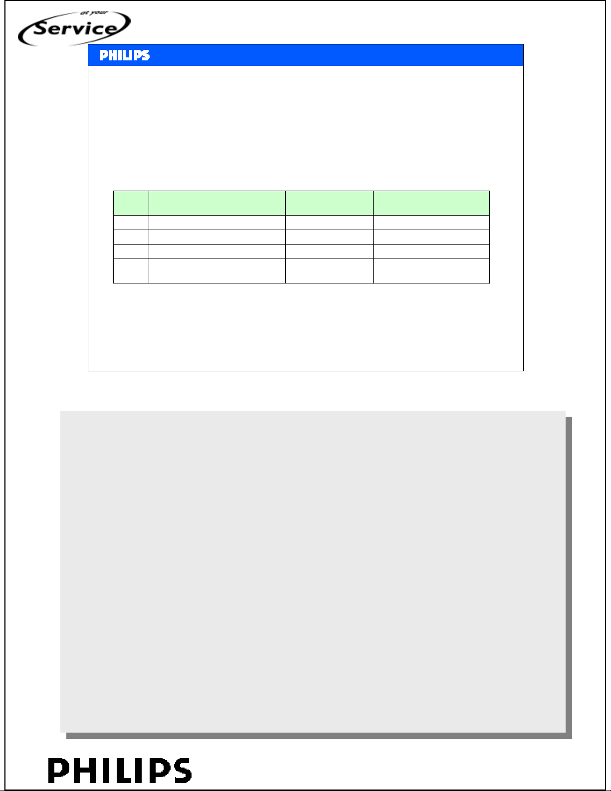
Before start up the sets, the SSB MUST load with the following diversity
related info:
SERVICE TRAINING
DescriptionsNo.
Location (Dec)
400Panel Option Code3
4
(Smart Sound profile)
Philips CE Europe, Euroservice, March 2007
Here is indicated on which addresses the value is stored.
Here is indicated on which addresses the value is stored.
i.e. the type number is stored on the addresses 200 until 212.
i.e. the type number is stored on the addresses 200 until 212.
407Option 7
RemarkTV NVM
i.e. 32PFL5522D/12200 - 212Product Model1
i.e. SV10003 30003215 - 228Serial No2
<service modes>, chapter: 9, Slide 9
PERSONAL NOTES:
PERSONAL NOTES:
© Copyright reserved 2002 Philips Consumer Electronics Euroservice
<< Service mode >>
chapter: 09 page: 9
Page 49
<< Service mode >>
<< Service mode >>
Option codes
SERVICE TRAINING
Philips CE Europe, Euroservice, March 2007
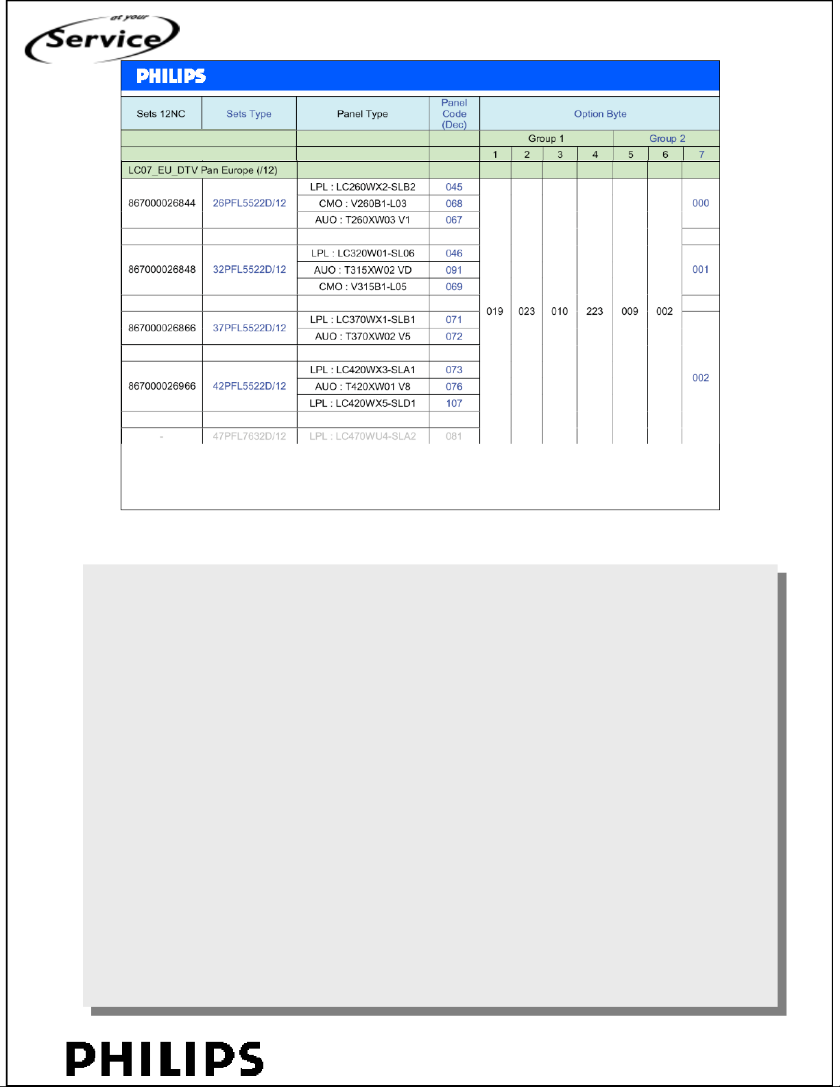
Option code table.
Option code table.
Last code is indication for screen size.
Last code is indication for screen size.
Every display has its own code, i.e. 32PFL5522D/12 with LPL-panel (code 46).
Every display has its own code, i.e. 32PFL5522D/12 with LPL-panel (code 46).
<service modes>, chapter: 9, Slide 10
PERSONAL NOTES:
PERSONAL NOTES:
© Copyright reserved 2002 Philips Consumer Electronics Euroservice
<< Service mode >>
chapter: 09 page: 10
Page 50
<< Service mode >>
<< Service mode >>
• Tuner AGC
– 15 (digital no alignment)
– For analogue only try 15
– Perfect alignment: insert IF and check voltage at
pin 1 of the tuner (analogue only)
SERVICE TRAINING
alignments
Philips CE Europe, Euroservice, March 2007
The analogue tuner UV1318S can also use the default value
The analogue tuner UV1318S can also use the default value
of “15”, however in case of problems use the following method
of “15”, however in case of problems use the following method
(use multimeter and RF generator):
(use multimeter and RF generator):
• Apply a vision IF carrier of 38.9 MHz (105 dBuV = 178
• Apply a vision IF carrier of 38.9 MHz (105 dBuV = 178
mVrms) to test point F111 (input via 50 ohm coaxial cable
mVrms) to test point F111 (input via 50 ohm coaxial cable
terminated with an RC network of series 10nF with 120
terminated with an RC network of series 10nF with 120
ohm to ground).
ohm to ground).
• Measure voltage on pin 1 of the tuner.
• Measure voltage on pin 1 of the tuner.
• Adjust AGC (via SAM menu: TUNER -> AGC), until voltage
• Adjust AGC (via SAM menu: TUNER -> AGC), until voltage
on pin 1 is 3.3 +0.5/-1.0 V.
on pin 1 is 3.3 +0.5/-1.0 V.
• Store settings and quit SAM.
• Store settings and quit SAM.
<service modes>, chapter: 9, Slide 11
PERSONAL NOTES:
PERSONAL NOTES:
© Copyright reserved 2002 Philips Consumer Electronics Euroservice
<< Service mode >>
chapter: 09 page: 11
Page 51
<< Service mode >>
<< Service mode >>
White drive
SERVICE TRAINING
Philips CE Europe, Euroservice, March 2007
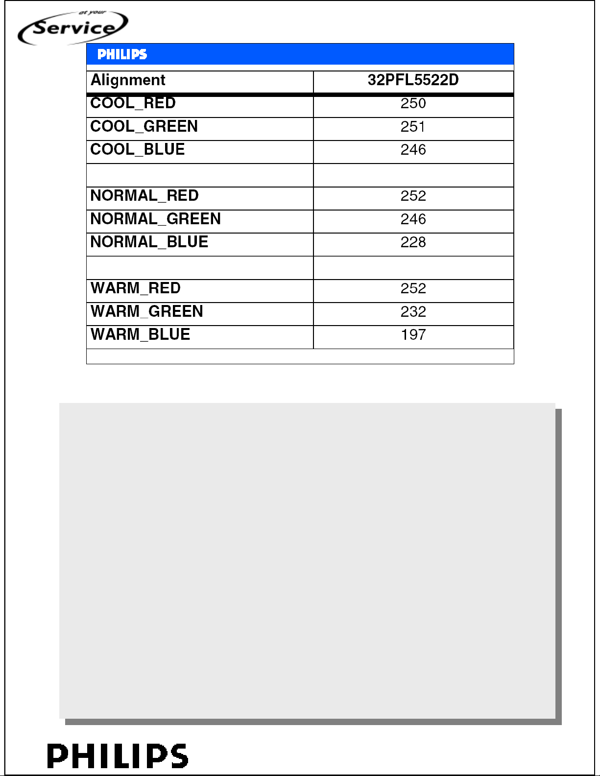
Indication is given for 32PFL5522D.
Indication is given for 32PFL5522D.
For perfect alignment colour analyser should be used.
For perfect alignment colour analyser should be used.
<service modes>, chapter: 9, Slide 12
PERSONAL NOTES:
PERSONAL NOTES:
© Copyright reserved 2002 Philips Consumer Electronics Euroservice
<< Service mode >>
chapter: 09 page: 12
Page 52
How to Program LC07 SW ?
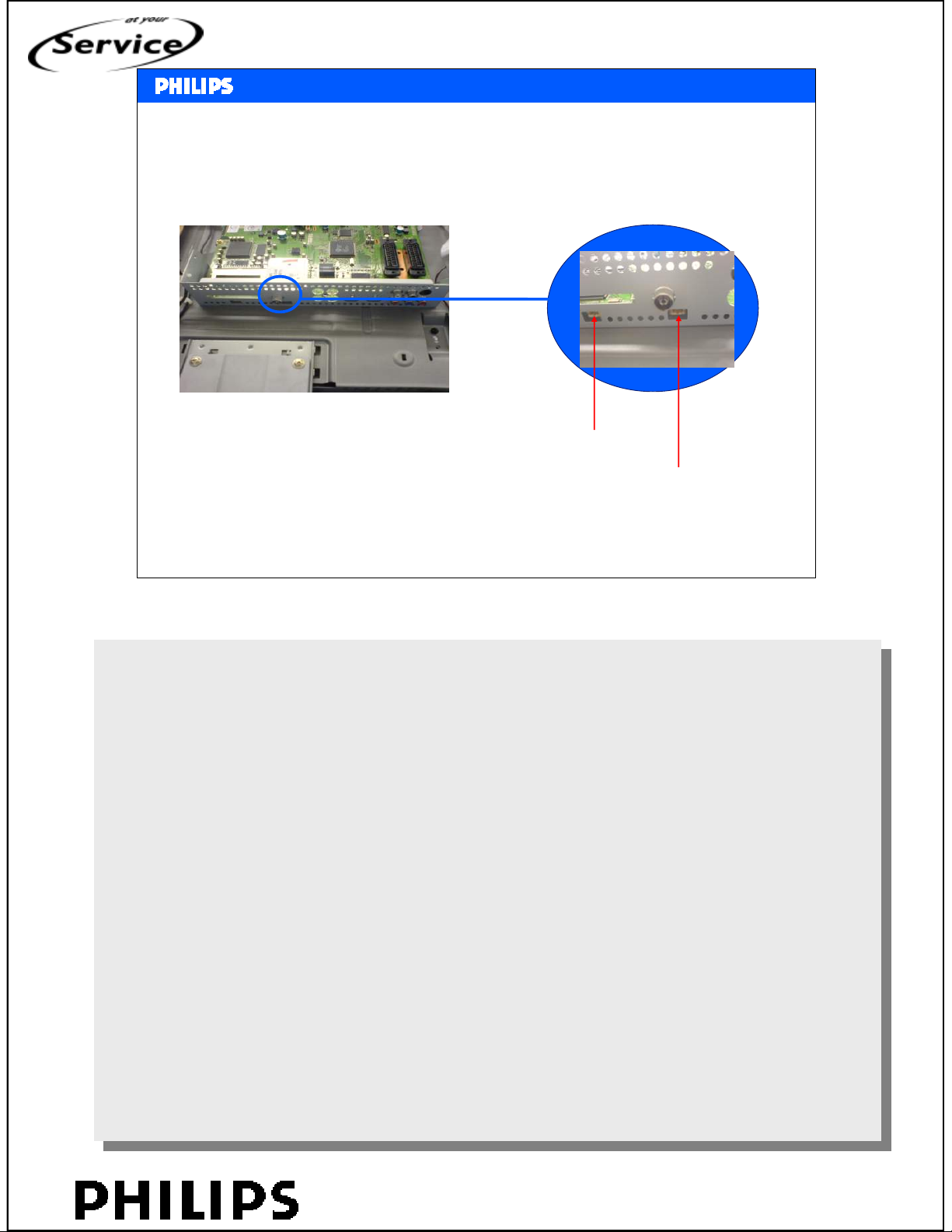
Behind the TV set connection for Compair
<< Service mode >>
<< Service mode >>
UART
Compair I2C
SERVICE TRAINING
Philips CE Europe, Euroservice, March 2007
Software update via Compair.
Software update via Compair.
The Compair program makes ues of the I2C connector.
The Compair program makes ues of the I2C connector.
UART is used for communication with the DVB-T hardware.
UART is used for communication with the DVB-T hardware.
Compair can update the software via UART.
Compair can update the software via UART.
<service modes>, chapter: 9, Slide 13
PERSONAL NOTES:
PERSONAL NOTES:
© Copyright reserved 2002 Philips Consumer Electronics Euroservice
<< Service mode >>
chapter: 09 page: 13
Page 53
<< Service mode >>
<< Service mode >>
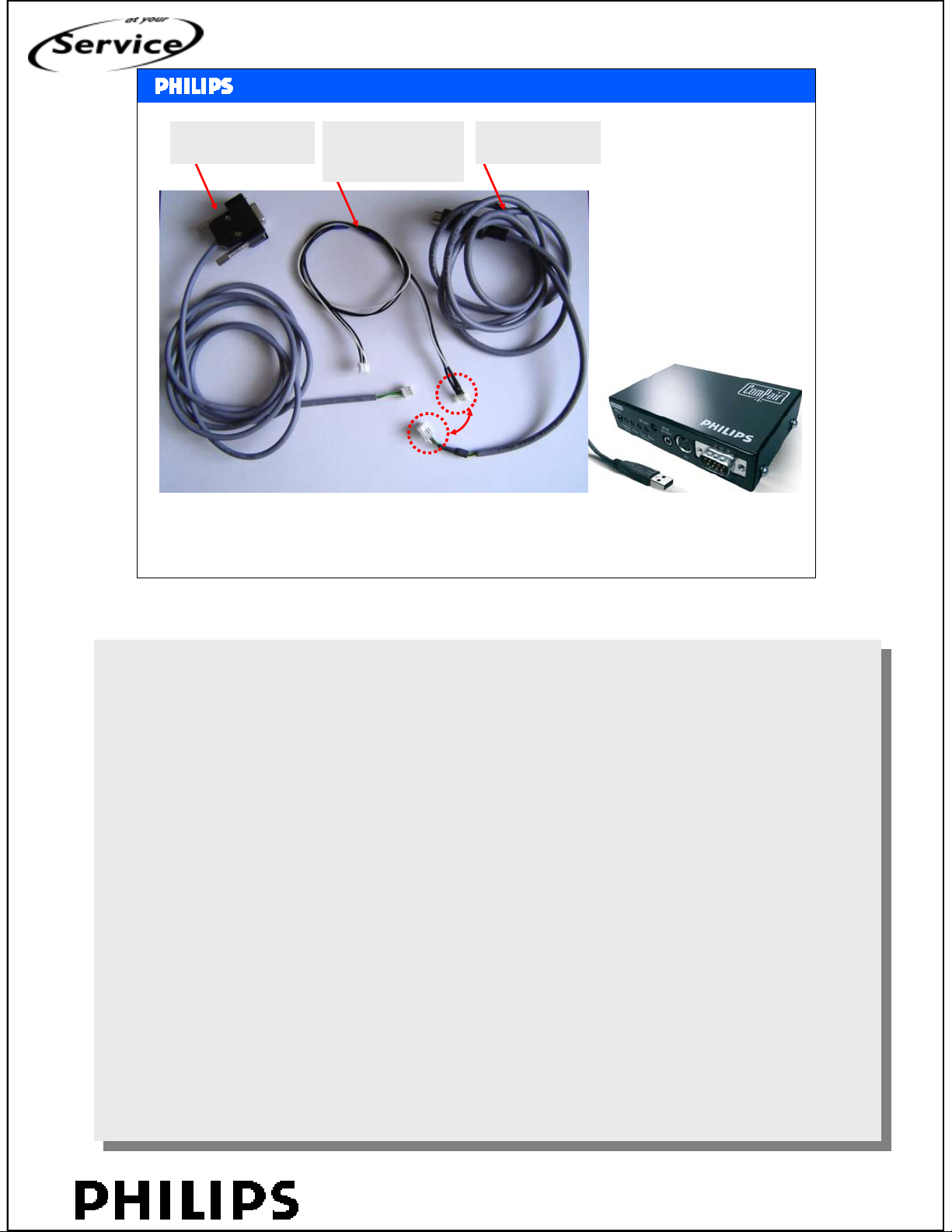
ComPair & UART Connector
SERVICE TRAINING
ComPair UART Cable
3122 785 90630
ComPair Interface
Philips CE Europe, Euroservice, March 2007
I²C Adaptor Cable
with small connector
3139 131 03791
ComPair I²C cable
3122 785 90004
<service modes>, chapter: 9, Slide 14
ComPair order codes (EU/AP/LATAM):
ComPair order codes (EU/AP/LATAM):
ComPair II order codes:
ComPair II order codes:
• ComPair II interface: 3122 785 91020.
• ComPair II interface: 3122 785 91020.
• ComPair32 CD (update): 3122 785 60160.
• ComPair32 CD (update): 3122 785 60160.
• ComPair interface cable: 3122 785 90004.
• ComPair interface cable: 3122 785 90004.
• ComPair interface extension cable: 3139 131 03791.
• ComPair interface extension cable: 3139 131 03791.
• ComPair UART interface cable: 3122 785 90630.
• ComPair UART interface cable: 3122 785 90630.
PERSONAL NOTES:
PERSONAL NOTES:
© Copyright reserved 2002 Philips Consumer Electronics Euroservice
<< Service mode >>
chapter: 09 page: 14
Page 54
<< Service mode >>
<< Service mode >>
SERVICE TRAINING
Philips CE Europe, Euroservice, March 2007
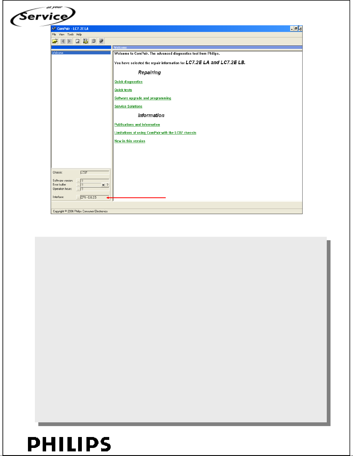
new interface detected
<service modes>, chapter: 9, Slide 15
PERSONAL NOTES:
PERSONAL NOTES:
© Copyright reserved 2002 Philips Consumer Electronics Euroservice
<< Service mode >>
chapter: 09 page: 15
Page 55
<< Service mode >>
<< Service mode >>
SERVICE TRAINING
Philips CE Europe, Euroservice, March 2007
<service modes>, chapter: 9, Slide 16
PERSONAL NOTES:
PERSONAL NOTES:
© Copyright reserved 2002 Philips Consumer Electronics Euroservice
<< Service mode >>
chapter: 09 page: 16
Page 56
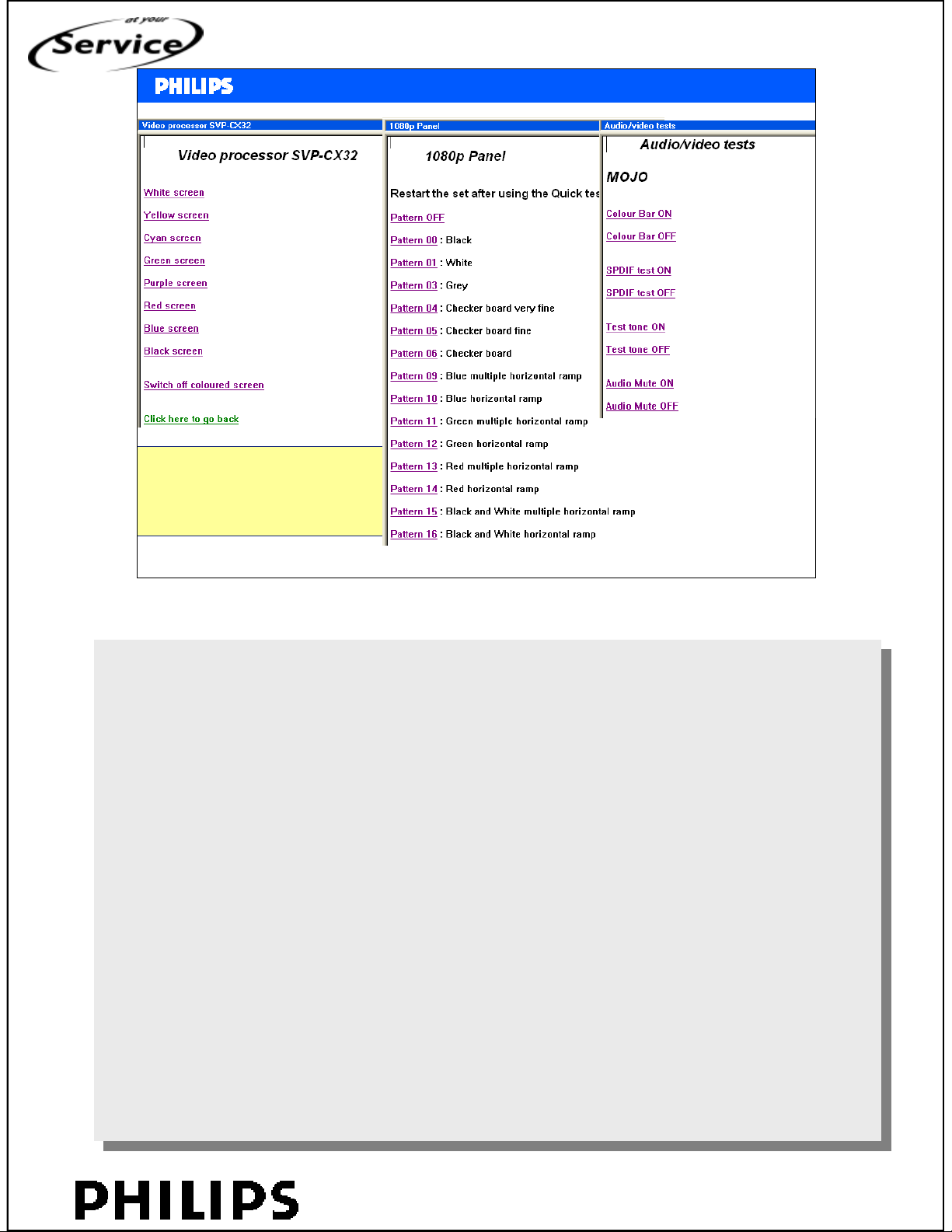
Various test pictures can
<< Service mode >>
<< Service mode >>
SERVICE TRAINING
be generated, from
trident, 1080p or MOJO
Philips CE Europe, Euroservice, March 2007
<service modes>, chapter: 9, Slide 17
PERSONAL NOTES:
PERSONAL NOTES:
© Copyright reserved 2002 Philips Consumer Electronics Euroservice
<< Service mode >>
chapter: 09 page: 17
Page 57
<< Service mode >>
<< Service mode >>
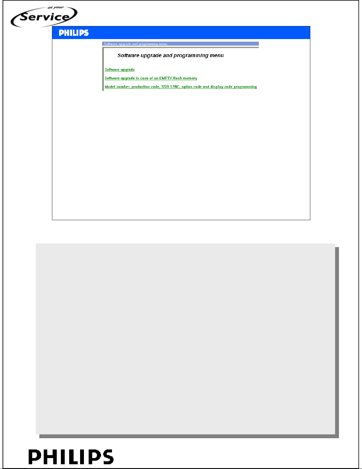
Select upgrade of the software or upgrade in case of empty flash *
(then there is no feedback that the set is in Compairmode)
If software upgrade is completed (inclusive nvm), then type
number, serial number, SSB, options have to be checked or
programmed
Check in CSM
SERVICE TRAINING
Philips CE Europe, Euroservice, March 2007
*
9322 212 72668 Empty flash does not work
<service modes>, chapter: 9, Slide 18
PERSONAL NOTES:
PERSONAL NOTES:
© Copyright reserved 2002 Philips Consumer Electronics Euroservice
<< Service mode >>
chapter: 09 page: 18
Page 58
<< Service mode >>
<< Service mode >>
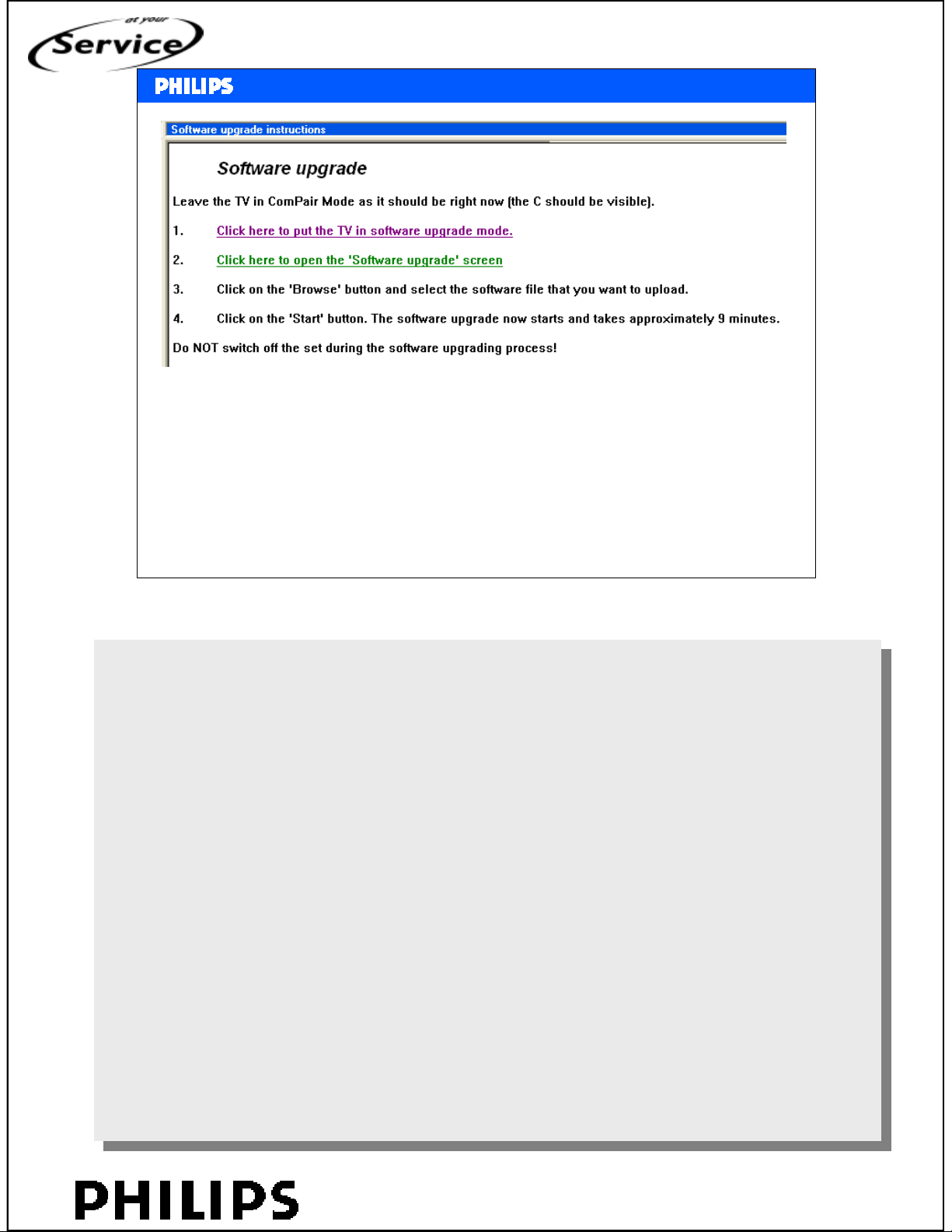
If the tv is in upgrade mode then the red LED is on
Shorten I2C connector, in case something went wrong.
SERVICE TRAINING
TV-set is now also in upgrade mode
Follow the procedure for empty flash
Philips CE Europe, Euroservice, March 2007
<service modes>, chapter: 9, Slide 19
PERSONAL NOTES:
PERSONAL NOTES:
© Copyright reserved 2002 Philips Consumer Electronics Euroservice
<< Service mode >>
chapter: 09 page: 19
Page 59

<< Service mode >>
<< Service mode >>
1. software upgrade,
2. nvm
3. Typenumber
4. Serialnumber
5. SSB
6. Options
SERVICE TRAINING
Philips CE Europe, Euroservice, March 2007
<service modes>, chapter: 9, Slide 20
PERSONAL NOTES:
PERSONAL NOTES:
© Copyright reserved 2002 Philips Consumer Electronics Euroservice
<< Service mode >>
chapter: 09 page: 20
Page 60
<< Service mode >>
<< Service mode >>
Upgrade nvm
• Set is in factory mode Æ V-/P- local keyboard
• Check displaycode
• Disconnect all cables after upgrade!!
SERVICE TRAINING
Philips CE Europe, Euroservice, March 2007
<service modes>, chapter: 9, Slide 21
PERSONAL NOTES:
PERSONAL NOTES:
© Copyright reserved 2002 Philips Consumer Electronics Euroservice
<< Service mode >>
chapter: 09 page: 21
Page 61
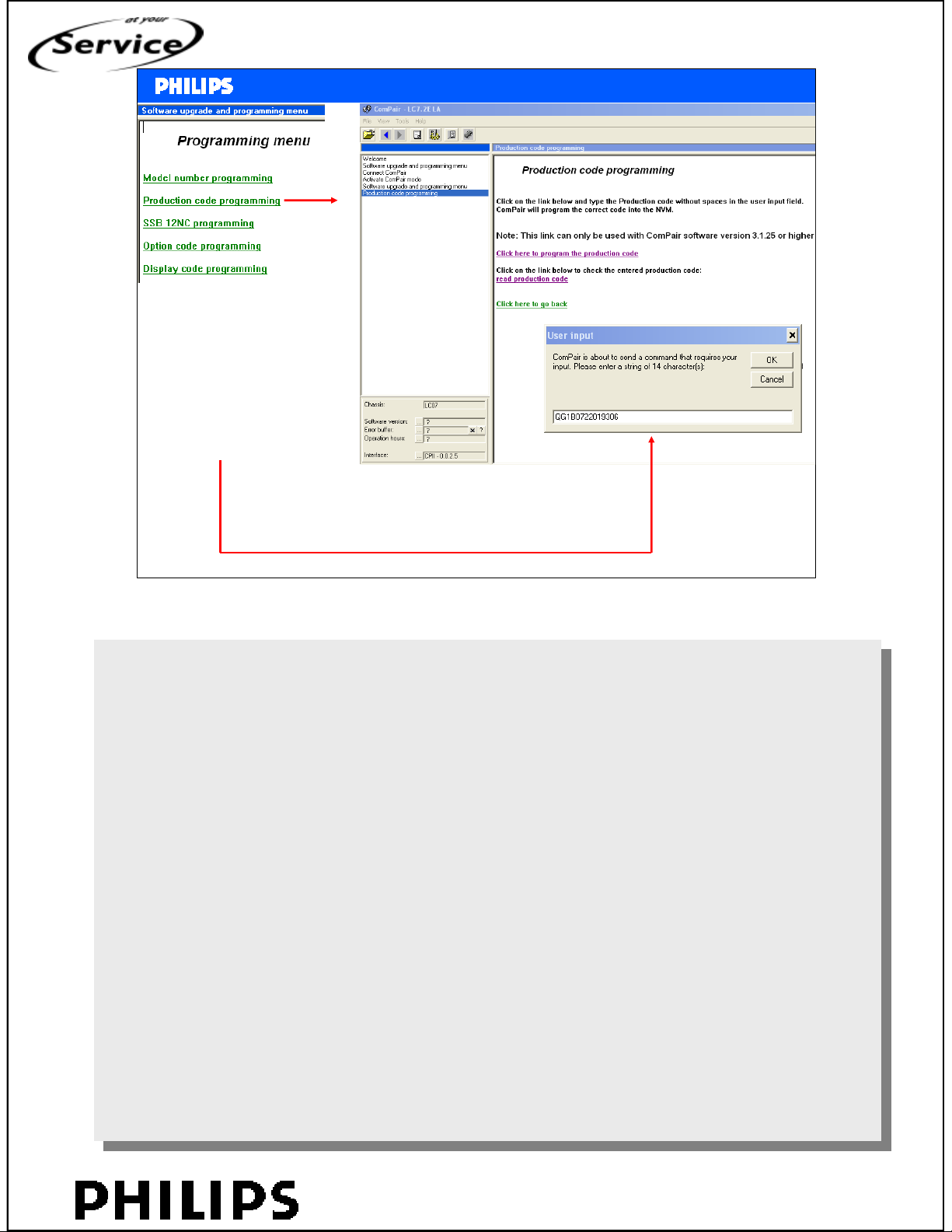
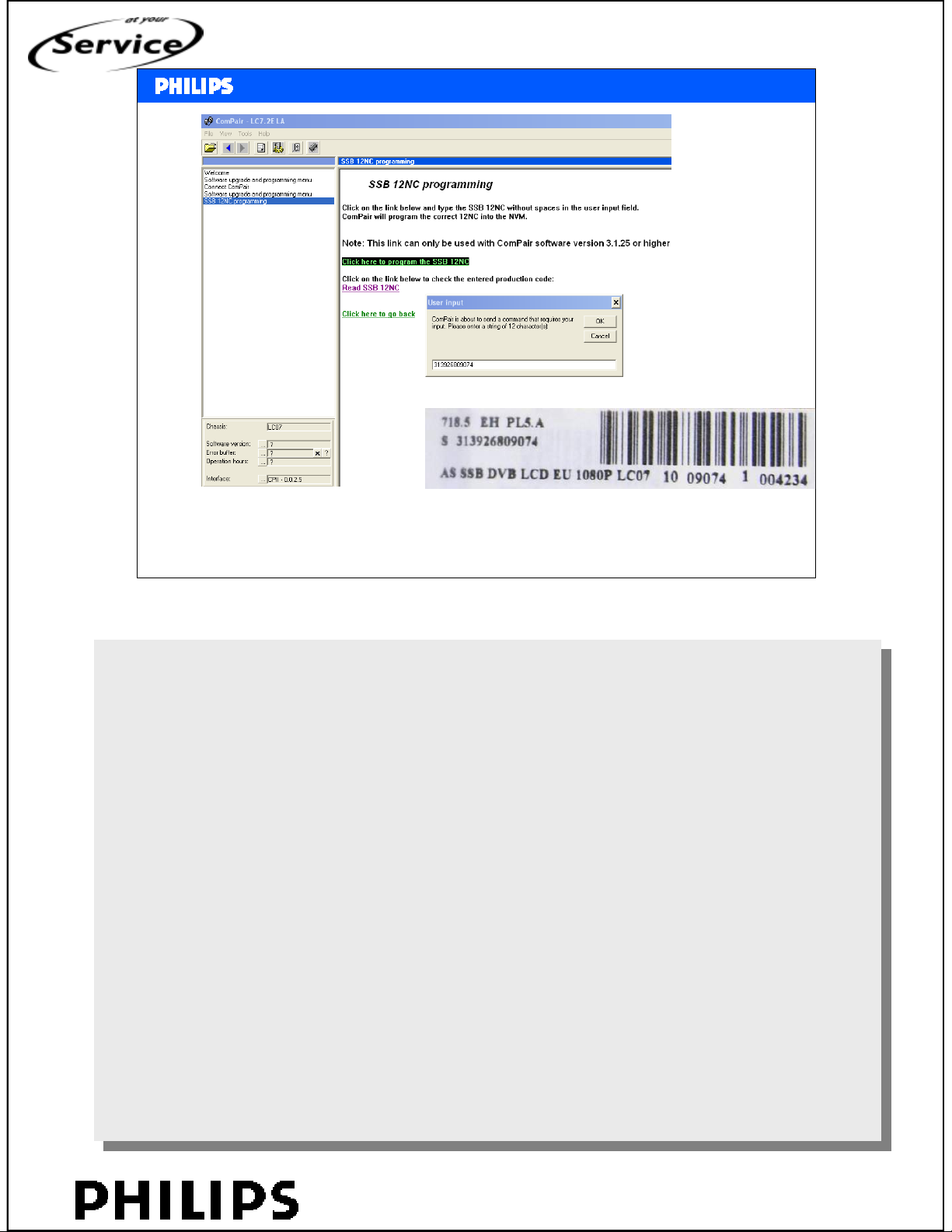
Pop-up screen will appear
where the serial number
can be entered
<< Service mode >>
<< Service mode >>
SERVICE TRAINING
Philips CE Europe, Euroservice, March 2007
<service modes>, chapter: 9, Slide 22
PERSONAL NOTES:
PERSONAL NOTES:
© Copyright reserved 2002 Philips Consumer Electronics Euroservice
<< Service mode >>
chapter: 09 page: 22
Page 62
<< Service mode >>
<< Service mode >>
SERVICE TRAINING
In the pop-up menu the 12NC can be entered
Philips CE Europe, Euroservice, March 2007
<service modes>, chapter: 9, Slide 23
PERSONAL NOTES:
PERSONAL NOTES:
© Copyright reserved 2002 Philips Consumer Electronics Euroservice
<< Service mode >>
chapter: 09 page: 23
Page 63
<< Service mode >>
<< Service mode >>
IBO software
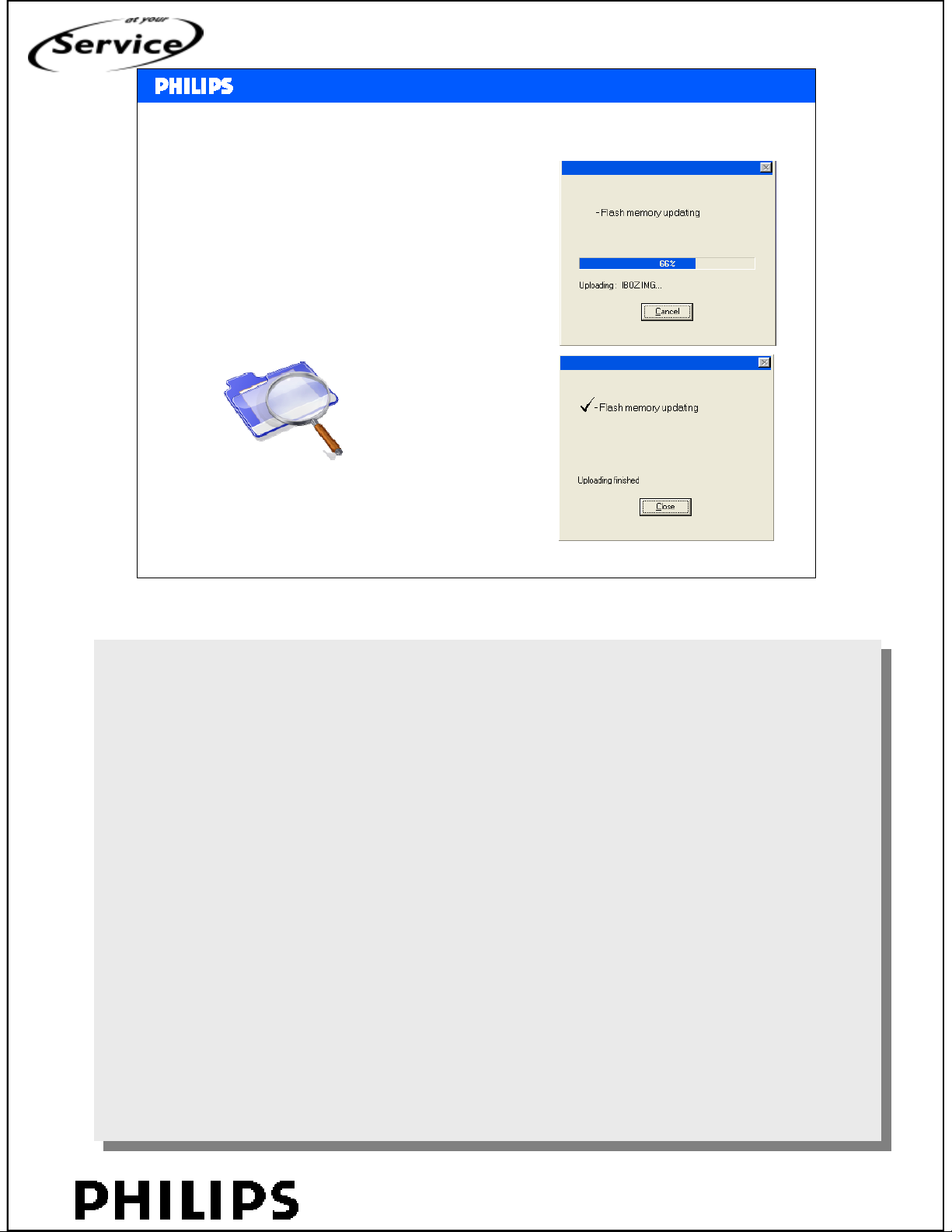
• Software upgrade for IBO (PCMCIA, OAD or Compair
• Nvm file (hyper terminal)
SERVICE TRAINING
Philips CE Europe, Euroservice, March 2007
<service modes>, chapter: 9, Slide 24
PERSONAL NOTES:
PERSONAL NOTES:
© Copyright reserved 2002 Philips Consumer Electronics Euroservice
<< Service mode >>
chapter: 09 page: 24
Page 64
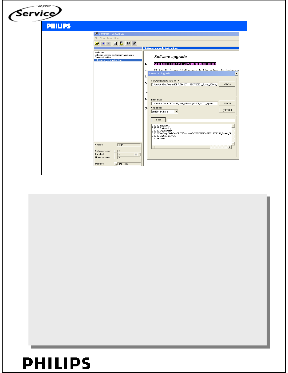
Via UART
connection on
1080p board
<< Service mode >>
<< Service mode >>
Software upgrade 1080p
SERVICE TRAINING
Philips CE Europe, Euroservice, March 2007
<service modes>, chapter: 9, Slide 25
PERSONAL NOTES:
PERSONAL NOTES:
© Copyright reserved 2002 Philips Consumer Electronics Euroservice
<< Service mode >>
chapter: 09 page: 25
Page 65

<< Service mode >>
<< Service mode >>
Nvm upgrade 1080p board
SERVICE TRAINING
Philips CE Europe, Euroservice, March 2007
<service modes>, chapter: 9, Slide 26
PERSONAL NOTES:
PERSONAL NOTES:
© Copyright reserved 2002 Philips Consumer Electronics Euroservice
<< Service mode >>
chapter: 09 page: 26
Page 66
<< Service mode >>
<< Service mode >>
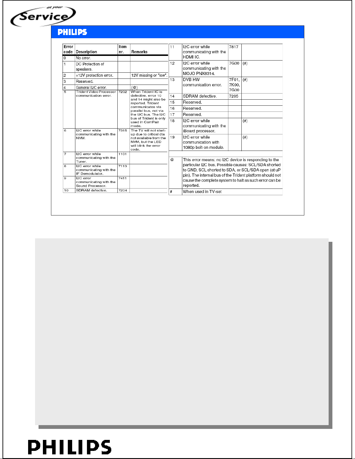
Error codes
SERVICE TRAINING
Philips CE Europe, Euroservice, March 2007
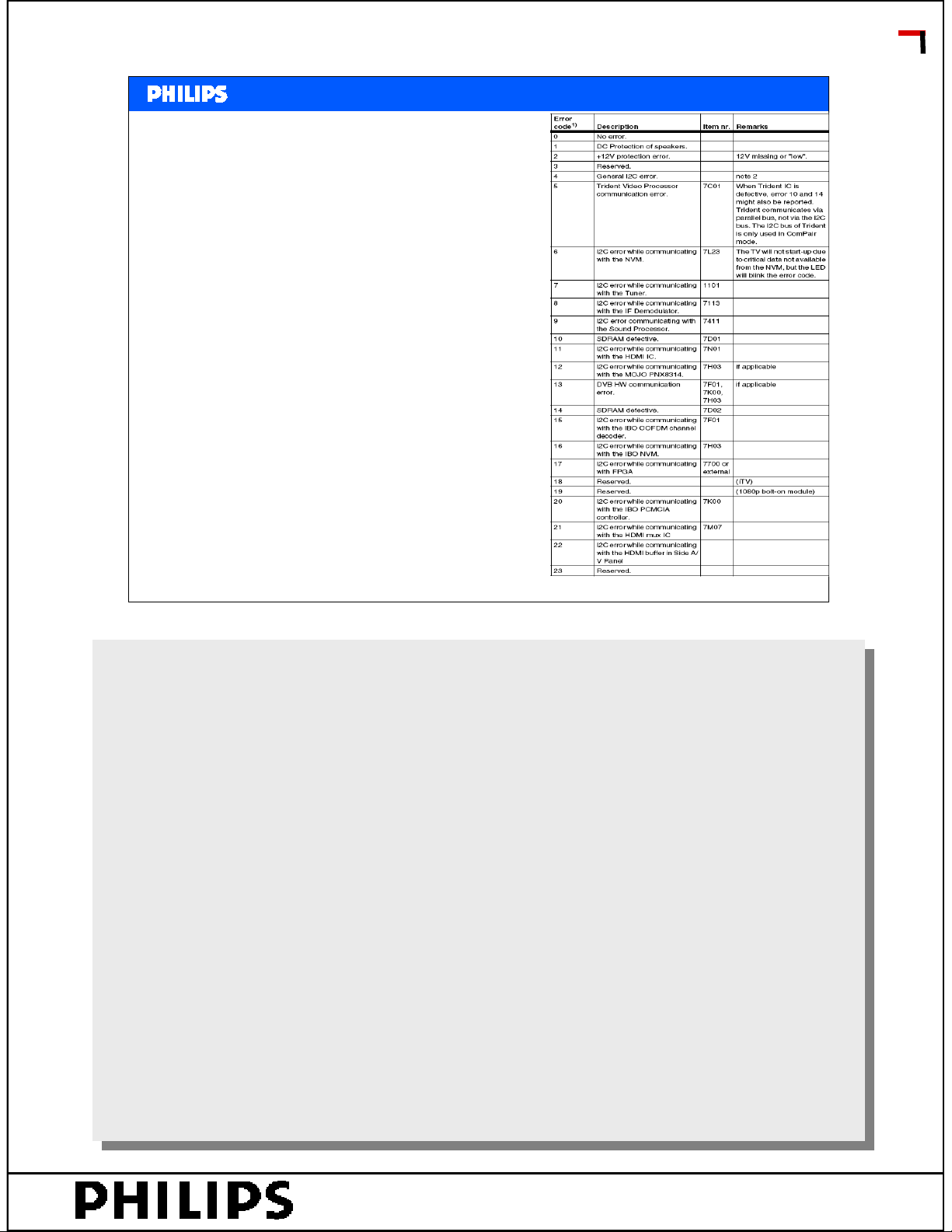
Error codes for LC7.
Error codes for LC7.
If there are problems with digital part, mostly there will be error 12.
If there are problems with digital part, mostly there will be error 12.
MOJO is the MPEG2 decoder, but also the processor for the digital part.
MOJO is the MPEG2 decoder, but also the processor for the digital part.
Error 6 means: no communication with nvm.
Error 6 means: no communication with nvm.
If there is any shortcircuit on I2C, this will also generate error 2.
If there is any shortcircuit on I2C, this will also generate error 2.
There are serial resistors on I2C, disconnect the resistors to determine which IC is causing the
There are serial resistors on I2C, disconnect the resistors to determine which IC is causing the
problem.
problem.
<service modes>, chapter: 9, Slide 27
PERSONAL NOTES:
PERSONAL NOTES:
© Copyright reserved 2002 Philips Consumer Electronics Euroservice
<< Service mode >>
chapter: 09 page: 27
Page 67
<< Service mode >>
<< Service mode >>
SERVICE TRAINING
PERSONAL NOTES:
PERSONAL NOTES:
© Copyright reserved 2002 Philips Consumer Electronics Euroservice
<< Service mode >>
chapter: 09 page: 28
Page 68
Hans Munsters
Philips CE - Euroservice
mainstream
August 2007
Frond End Filtering
<< chassis LC7 >>
<< chassis LC7 >>
SERVICE TRAINING
PERSONAL NOTES:
PERSONAL NOTES:
© Copyright reserved 2007 Philips Consumer Electronics Euroservice
<< front end filtering >>
page: 1
Page 69
• No picture
– Try other sources (scart, analogue or digital)
– Is there menu? Try OSD (i+)
– Only sound? Æ display problem ?
– Backlight?
• Stripes or 1 line constant visible?
• Teletext problem?
– All presets?
– Only 1 preset, then try to retune
– 10 pages memory, can be feature
<< chassis LC7 >>
<< chassis LC7 >>
Possible problems
SERVICE TRAINING
– Txt from other source? Æ settopbox or sattuner. Switch to other
external source to refresh txt-memory.
– Wrong characters? Check country selection
Philips CE Europe, Euroservice, August 2007 Front end filtering, slide2
PERSONAL NOTES:
PERSONAL NOTES:
© Copyright reserved 2007 Philips Consumer Electronics Euroservice
<< front end filtering >>
page: 2
Page 70
• Check LED
– No LED
– Only red
– Green
– Blinking? Æ error code
• Error 1 audio
• Error 2 power supply?
• Error 12 DVB-T
<< chassis LC7 >>
<< chassis LC7 >>
No function or partly working
SERVICE TRAINING
• Error 19 1080p module
Philips CE Europe, Euroservice, August 2007 Front end filtering, slide3
PERSONAL NOTES:
PERSONAL NOTES:
© Copyright reserved 2007 Philips Consumer Electronics Euroservice
<< front end filtering >>
page: 3
Page 71
Problem solved with new software?
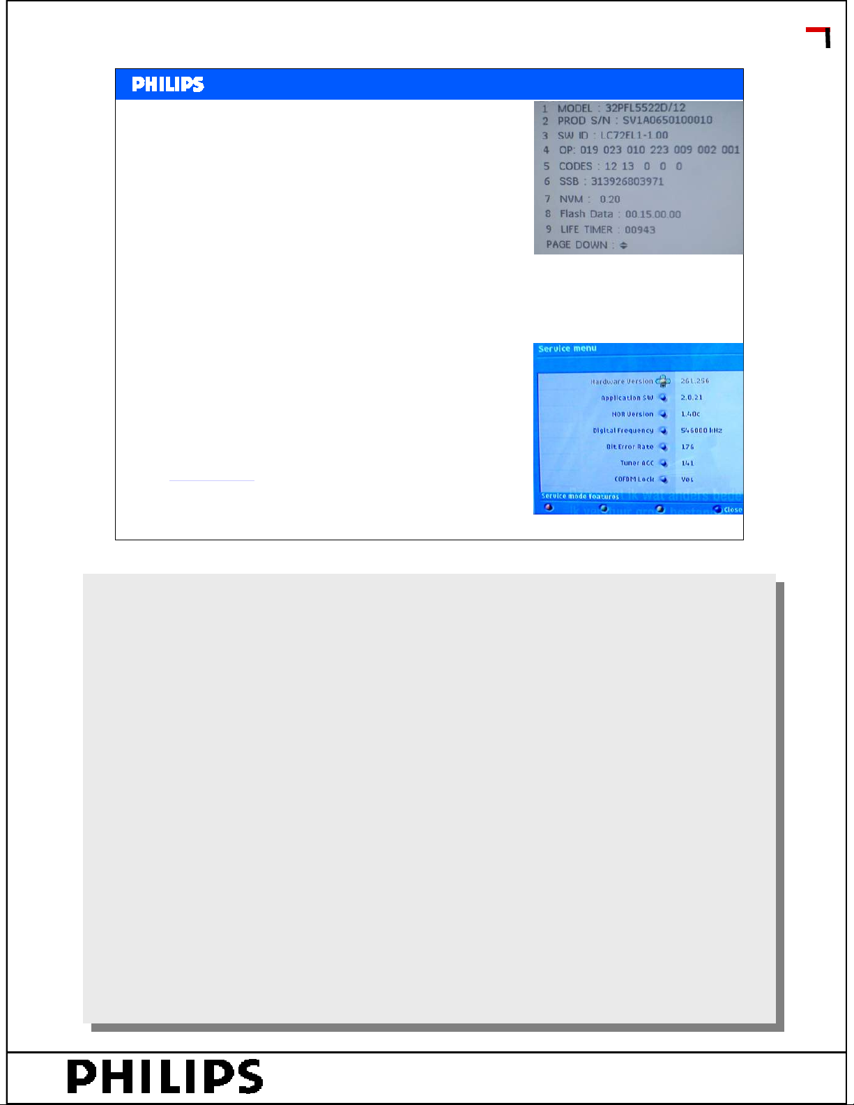
• Check software version
– Analogue or digital mode?
• Analogue - -main software (compair)
– Check version via CSM 1,2,3,6,5,4
• Digital (memory card)
– Check software via DCSM 1,2,3,6,5,4
– Via digital menu select info
<< chassis LC7 >>
<< chassis LC7 >>
SERVICE TRAINING
Release notes?
Philips CE Europe, Euroservice, August 2007 Front end filtering, slide4
PERSONAL NOTES:
PERSONAL NOTES:
© Copyright reserved 2007 Philips Consumer Electronics Euroservice
<< front end filtering >>
page: 4
Page 72
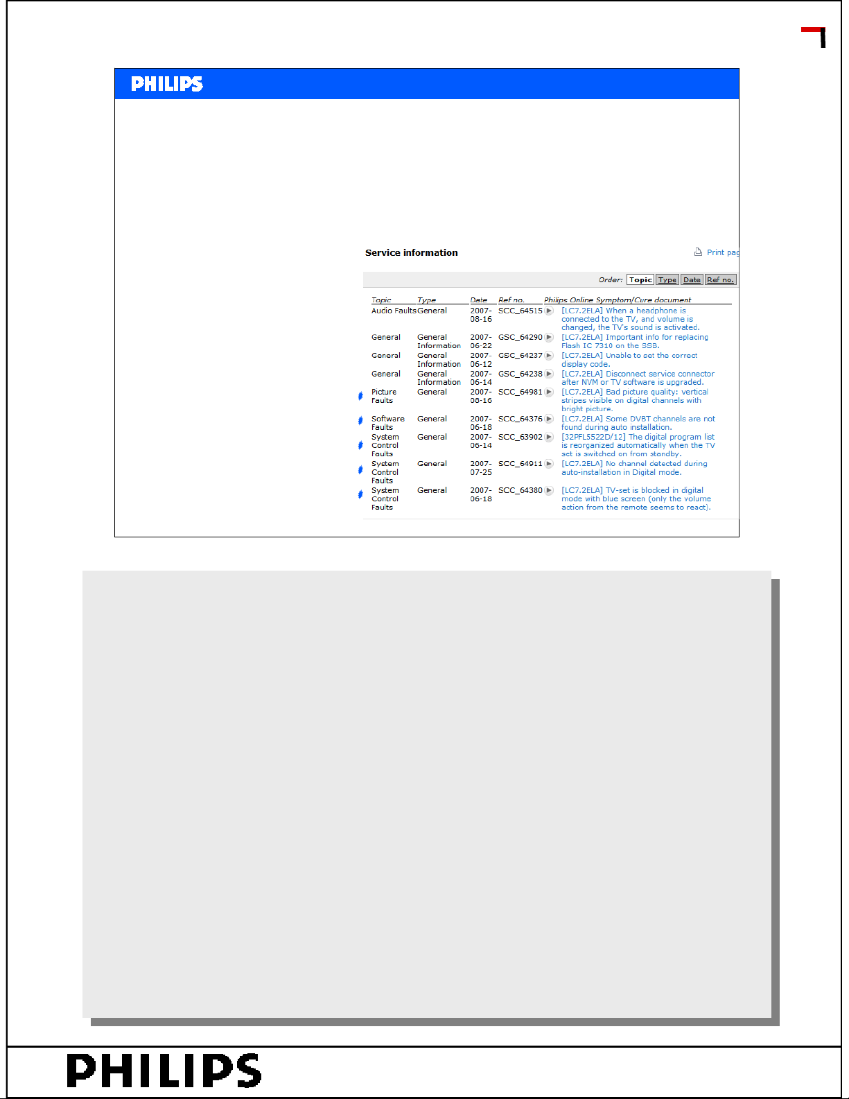
• Some channels not ok?
– Check antenna connection, try other tv
– Retune channels
– V+/- back in virgin mode
• Problem only in digital mode?
– Check symptom-cure
<< chassis LC7 >>
<< chassis LC7 >>
Tuning problem
SERVICE TRAINING
Philips CE Europe, Euroservice, August 2007 Front end filtering, slide5
PERSONAL NOTES:
PERSONAL NOTES:
© Copyright reserved 2007 Philips Consumer Electronics Euroservice
<< front end filtering >>
page: 5
Page 73
<< chassis LC7 >>
<< chassis LC7 >>
Remote is not working
• Factory mode?
– Vol – and P- (local keyboard) to disable factory mode
– ‘F’ is displayed on screen
• Volume at max?
– Keyboard defect?
• Virgin mode
– Vol – and Vol + (local keyboard)
SERVICE TRAINING
Philips CE Europe, Euroservice, August 2007 Front end filtering, slide6
PERSONAL NOTES:
PERSONAL NOTES:
© Copyright reserved 2007 Philips Consumer Electronics Euroservice
<< front end filtering >>
page: 6
Page 74
<< chassis LC7 >>
<< chassis LC7 >>
Problems with HDMI
• Try other resolutions
• PC-mode or video mode?
• Overscan – underscan
• Can customer try other set? (or in the shop?)
SERVICE TRAINING
Philips CE Europe, Euroservice, August 2007 Front end filtering, slide7
PERSONAL NOTES:
PERSONAL NOTES:
© Copyright reserved 2007 Philips Consumer Electronics Euroservice
<< front end filtering >>
page: 7
Page 75
Problems with component input
• What does customer use?
– 1fH, 2fH, …
• Try sync via side I/O
– Picture? Æ 1fH
– No picture Æ 2 or 3fH (higher frequency)
• Check settings in DVD-player
– Try RGB or CVBS
• Try other tv
<< chassis LC7 >>
<< chassis LC7 >>
SERVICE TRAINING
Philips CE Europe, Euroservice, August 2007 Front end filtering, slide8
PERSONAL NOTES:
PERSONAL NOTES:
© Copyright reserved 2007 Philips Consumer Electronics Euroservice
<< front end filtering >>
page: 8
Page 76
<< chassis LC7 >>
<< chassis LC7 >>
SERVICE TRAINING
PERSONAL NOTES:
PERSONAL NOTES:
© Copyright reserved 2007 Philips Consumer Electronics Euroservice
<< front end filtering >>
page: 9
Page 77
Chassis LC7.1E – LC7.2E
The LC7.x is a new mainstream tv-chassis introduced in the year 2007 (LC7.1 is the
analogue range, LC7.2 is the digital range). It is the successor of the LC4.x chassis, and
covers a screen size of 26 to 52 inch for LCD and 42 to 50 inch for Plasma sets with a
new styling called “ME7”.
Some key components are:
• Audio: Sound processing is via multi-standard sound processor MSP4450 (7411)
• Video: Video processing is with the Trident video processor SVP CV32-LF (7202).
For analogue reception, a standard IF demodulator is used, whereas digital input signals
(DVB-T) are processed through a COFDM channel decoder together with an MPEG
decoder (integrated on the SSB).
A so-called “Renesas” microprocessor performs the control functionality.
Important features of this chassis are:
• AmbiLight: LED AmbiLight (optional)
• 1080p Full HD (where applicable).
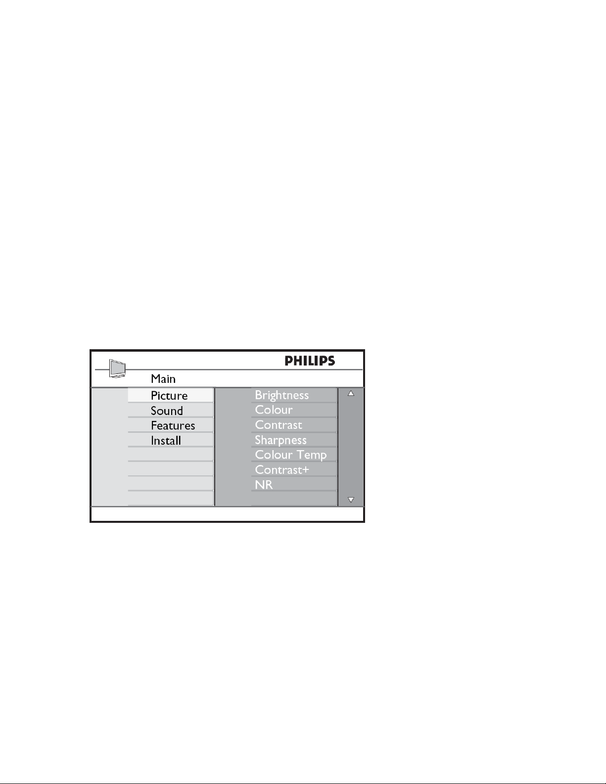
The user interface for LC7 (analogue mode):
The menu looks similar as used in chassis L06 (CRT-set), but 100Hz features are not
present here. LC7 has 1000 pages txt, so there is big memory.
For picture format switching there is no black bar detection, auto format is via signalling
bits or via status on pin 8 of scart.
Via A/D button on the remote you can switch to digital mode.
The digital menu is the same as used in LC4 or FTx2:
Page 78
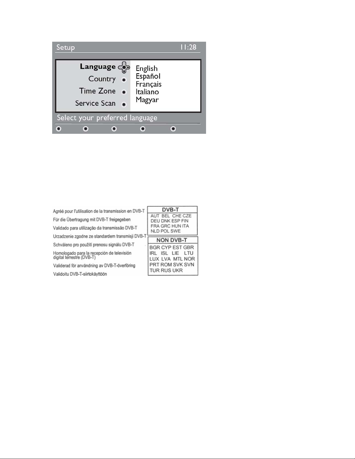
So there are 2 menu buttons on the RC (analogue menu or digital menu).
There is no longer SPDIF output.
At the rear side of a digital set there is a sticker for DVB-T or non-DVB-T countries.
This is indication of validation in those countries. If non-DVB-T country is selected the
digital reception is disabled (introduced with software R0C44).
If non dvb-t country is selected then it is still possible to switch to digital mode, but no
digital channels are stored.
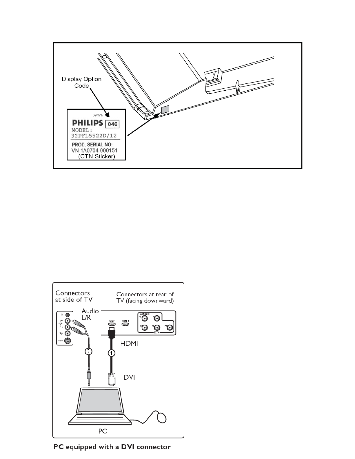
At the bottom side of the set there is sticker with typenumber, serialnumber.
Also the display code is mentioned here. If there is no picture, then a quick check could
be to reprogram display code (via 062598 menu xxx).
But attention, in CSM typenumber and serialnumber are reset.
Page 79
LC7 is used as main stream product, for lower end CFD (Commodity Flat Display) is
used. At this moment different chassis are used:
LC4.1E AC update of LC4.1E AB
LC7.2E LB small change compared with LC7.2 LA
TPS1.0E LCD-set with chassis from TPV
In LC7 there are 2 scart connectors, EXT1 is full scart (with RGB) and EXT2 is meant
for DVDR (YC is on EXT2).
2 HDMI connectors are used and LC7 has also component input (1fH/2fH supported).
At the side is input for CVBS, YC and audio i.e. from camera.
There is also the headphone connector. LC7 has only 1 volume control, there is no
separate control for headphone.
For Europe there is no VGA
connection, but computer can be
connected via DVI-HDMI cable.
Audio from PC should be connected to
front.
Page 80
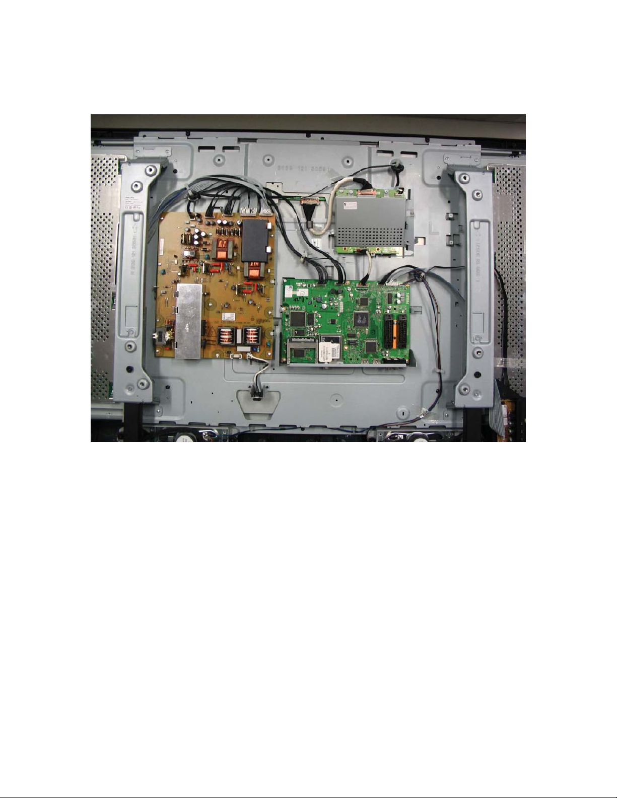
Mechanical setup of the set.
In LC7 there are only few boards. On the SSB is the DVB-T (IBO) module integrated.
Compared with LC4 there is only 1 tuner, this is so-called hybrid tuner. It is used for
analogue and digital reception.
The audio amplifier (class D) is on the SSB.
The SSB has to be repaired on component level (complete board cannot be ordered).
In sets with full HD display, the 1080P panel is added.
LVDS signal from SSB (single LVDS) is fed to the 1080P board, output is dual LVDS to
the LCD-panel.
The 1080P board is supplied with 12V and IIC is via the LVDS connector.
Page 81
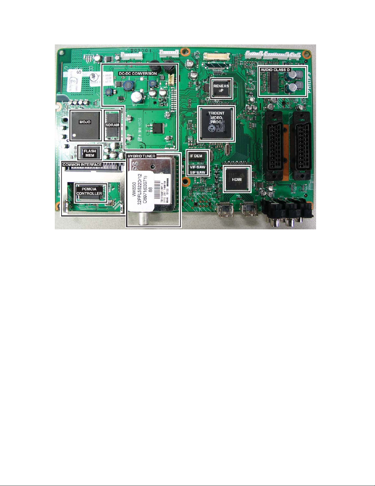
In this picture the components are indicated. Basic concept of chassis LC7 is built with
Renesas (main uP) and Trident (video processor). There are 2 HDMI connectors, via
HDMI chip selection is made. (in this chip the HDCP-keys are integrated)
On the left side is the DVB-T part, it is the same hardware as used in LC4.
The audio amplifier is without cooling plate, because of class D (high efficiency).
Page 82
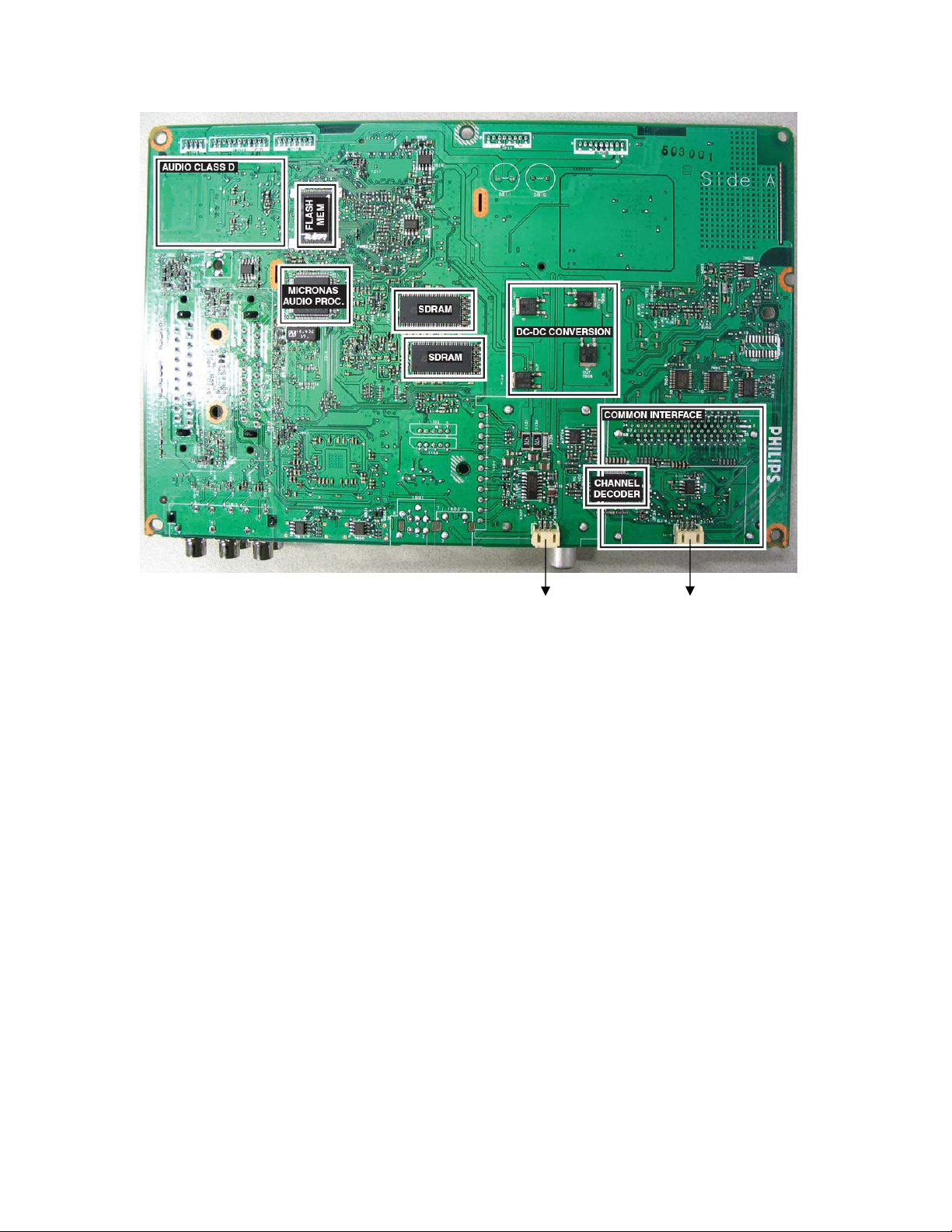
I2C UART
This is the rear side of the SSB.
Here is the audio processor, the IC is from micronas.
Above it is the flash mem indicated, here is the main software of the set.
2x SDRAM is used for the Trident video processor, this is used to store the video signal
so the Trident can do calculations on the video signal i.e. scaling, widescreen switching
or picture improvements like pixel plus.
The memory is also used for storing 1000 txt pages.
Channel decoder does the tuning in DVB-T mode.
I2C connector is used for Compair, i.e. for software upgrading.
The UART connector is used for the DVB-T part of LC7.
Page 83
Power supply
312242724571
(
)
The power supply is handled as black box.
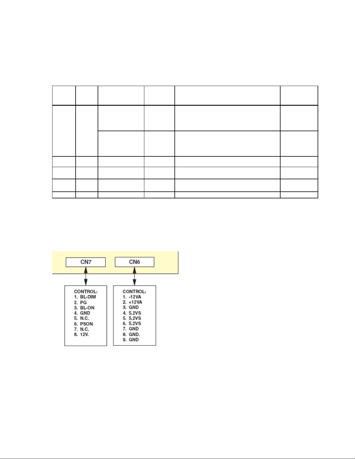
This means that the service policy for all power supplies in LC7 is board swap.
In this table the versions are indicated:
Screen
& 32" LCD
26"
37" & 42" LCD
47" LCD
42" PDP 996500045386 SDI Global Reuse 2K6 wit h mi nor m odification 90 ~ 265
50" PDP Global Reuse 2K6 with minor modification 90 ~ 265
Screen
Type
12 nc Re gi on PSU Description/ Type Numbe r
313912878521
(DELTA)
312242724431
(PPS)
313912878451
(DELTA)
312242724521
(PPS)
PPS
313912878921
(DELTA)
Europe
Global LC06 Integrated P S U 2632" - ROW 90 ~ 265
Global LC06 Integrated PSU 3742" GLOBAL 90 ~ 265
Global LC06 Integrated PS U 47" GLOBAL 90 ~ 265
LC06 Integrated w/o bol t-on PSU 2632" Europe
Operating
Voltage Range
198 ~ 265
For LCD use is made of 2 suppliers: Delta and Philips Power Solutions. With Plasma sets
power supply is dependent on the used pdp.
Measure the voltages at the connectors of the power supply, to have a quick indication
whether the supply is ok. The power supply can also operate without load.
One remark for digital set:
If set is switched into standby, then there is semi standby.
This is not indicated by the LED’s, but after about 10 minutes the set will switch to
standby (low power consumption). In semi standby the power consumption is +/- 20W.
Semi standby is used in LCD, but also with PDP.
This semi standby mode is used to scan for new channels and to check whether new
software is available.
Page 84
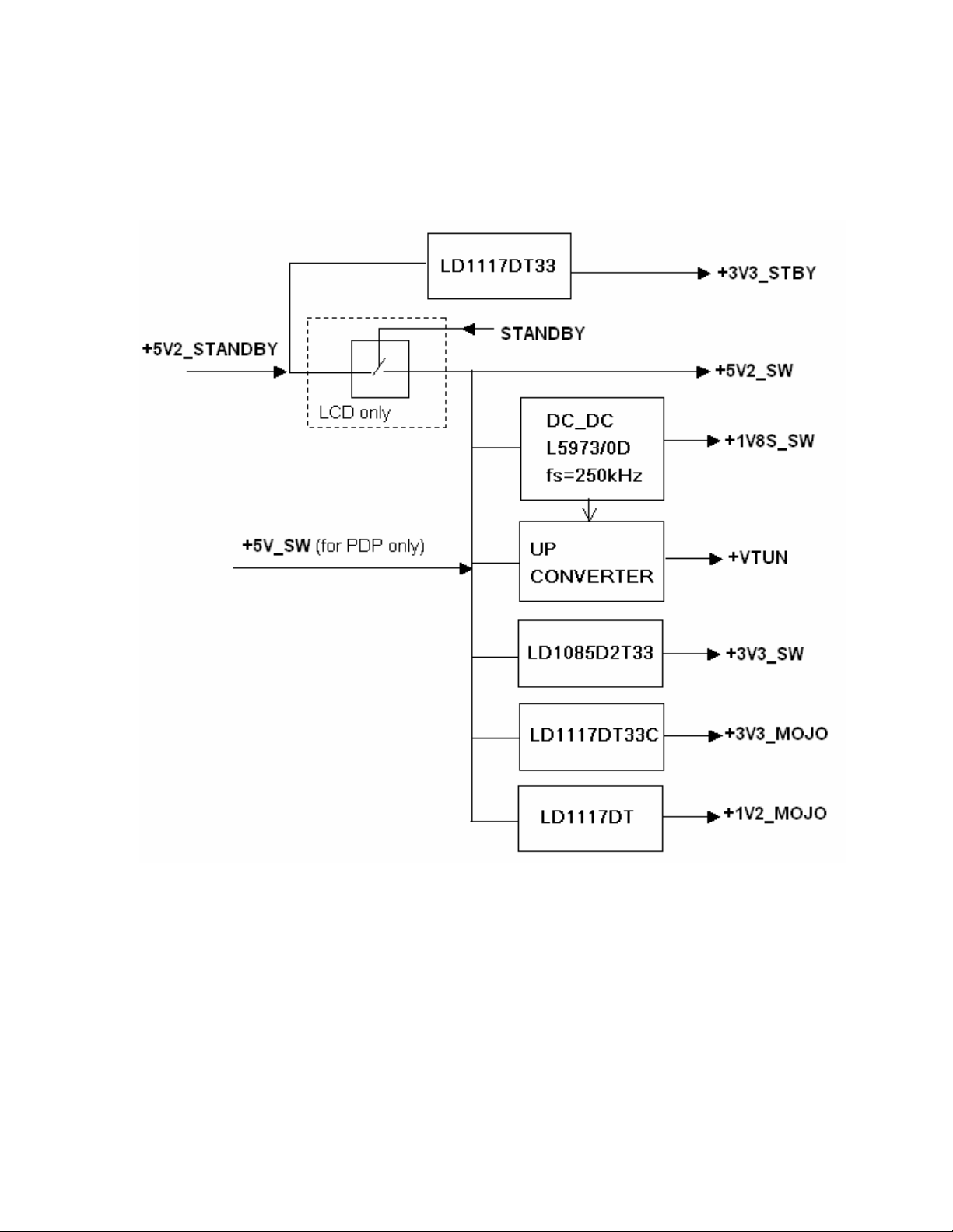
On the SSB is part of the power supply. From the 5V_SW several voltages are derived.
In this part there is one serial switch mode (L5973D) and the rest are voltage stabilisers
(except for Vtun).
The DC-DC converter is a serials switch mode supply. It works at switching frequency
of 250kHz.
5V2_SW can be from power supply, in case of PDP-set. In case of LCD-sets then the
switching is on the SSB.
In standby mode the 3V3_STBY remains present, therefore only the Renesas is active
during standby.
Page 85
Tuning and IF
V
A
7113
IF demodulator
RF AGC_analog
CVBS
SIF
RF AGC_digital
IIC_analog
IIC_digital
Supply
+5V/+33V
4MHz clock
To COFDM
1101
tuner
IF AGC
ideo
SAW
udio
SAW
RFAGC
7111
Switch
IC
IIC
Digital IF
36.16MHz
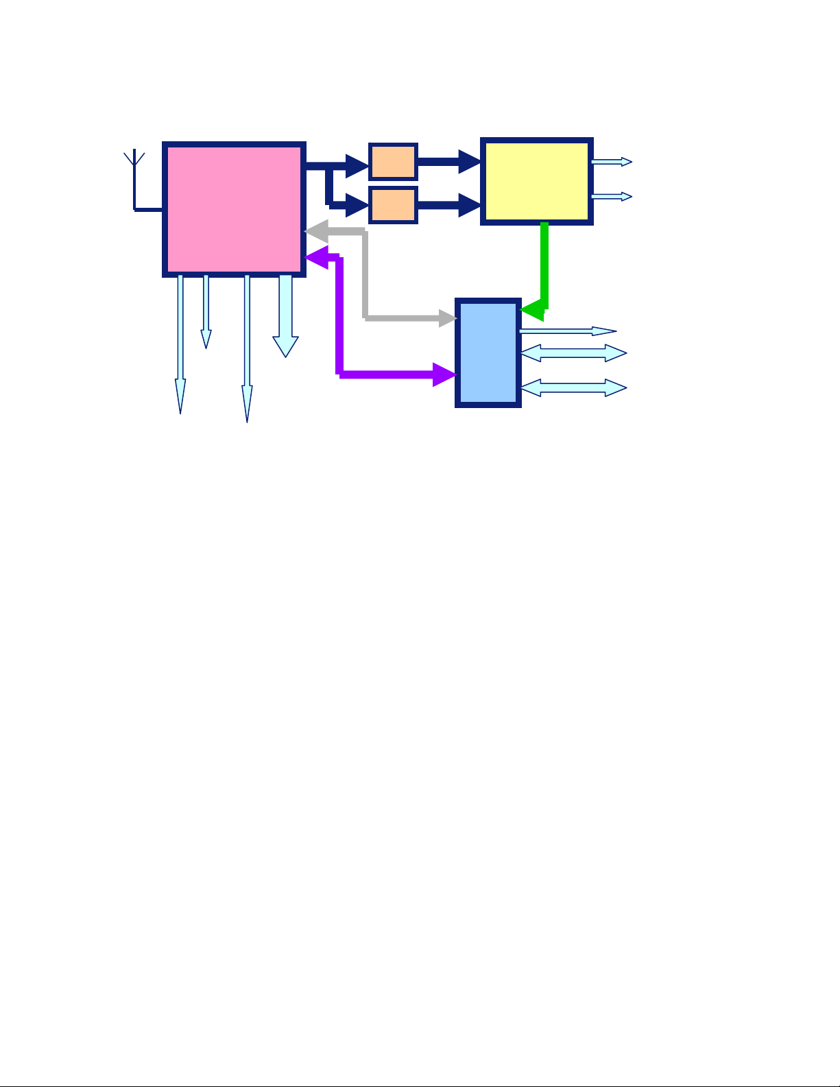
In chassis LC7 there is a hybrid tuner (1101), it is used for analogue and digital tuning.
Via IC7111 the I2C bus is switched, IIC analogue is from the Renesas and IIC is from the
channel decoder.
For analogue reception RF AGC is used, but for digital this is inside the tuner and then
IF AGC is used. (analogue tuner or hybrid tuner are not interchangeable)
The DVB-T hardware is based on the IBO module which is also used in LC4 chassis.
The main control of DVB-T is the MOJO chip. The Renesas communicates with the
MOJO via the IIC bus and the MOJO controls via local IIC the DVB-T part.
The DVB-T cell on the SSB is built around the “MOJO” MPEG decoder PNX8314HS
(item 7G00) and receives the signal from the COFDM Channel Decoder TDA10046
(item 7F01). The (hybrid) tuner TD1316AF (item 1101) supports digital (DVB-T)
reception and transports the signal via the VIM_IBO and VIP_IBO lines. The digital data
stream exits the DVB-T cell when it is fed to the Trident SVP CX32 Video Processor
(item 7202). A Common Interface (CI) slot allows reception of encoded signals when
Page 86
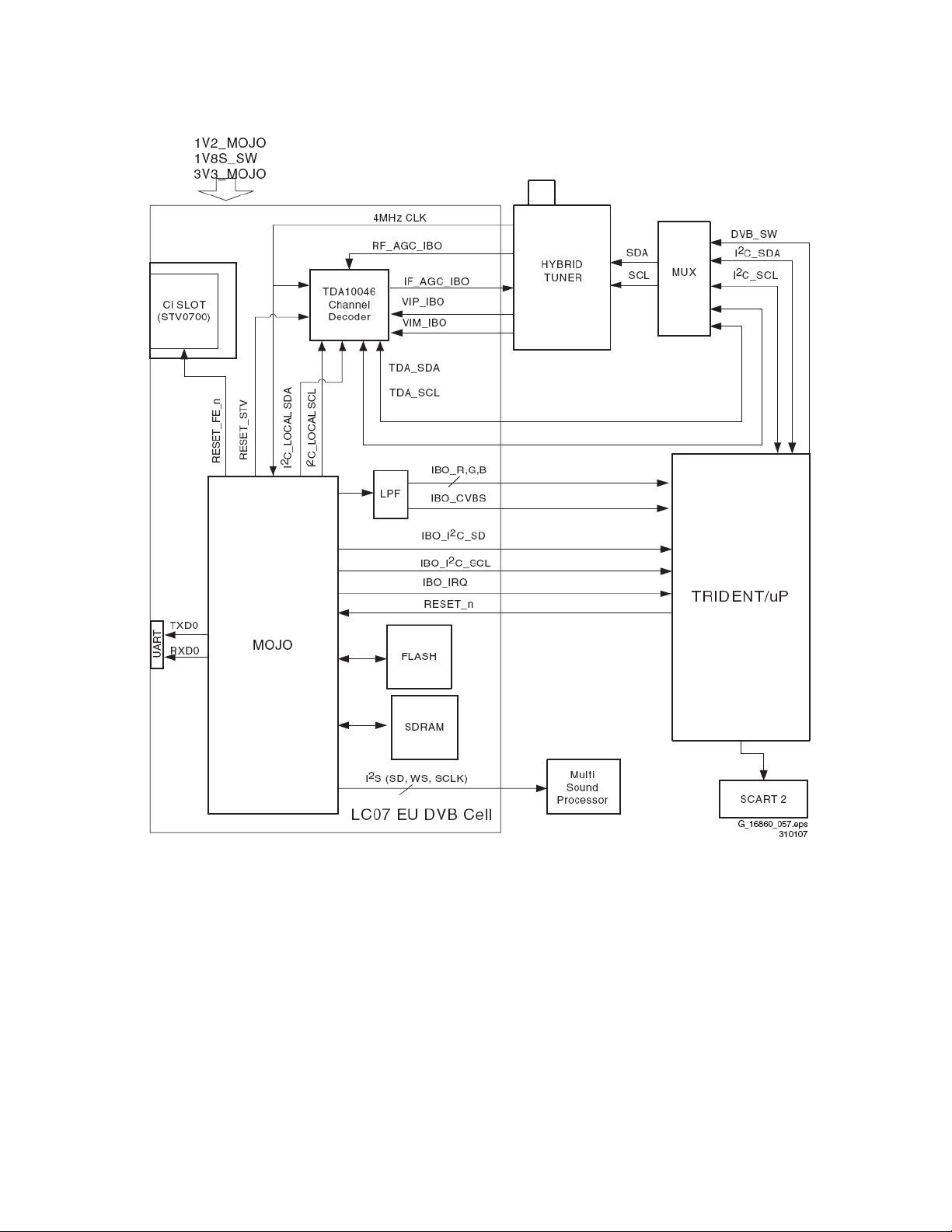
used with a Conditional Access Module (CAM) in combination with a smart card.
Common Interface (CI)
Introduction
The digital sets of this chassis are provided with a special slot called Common Interface
(CI). Together with a Conditional Access Module (CAM) and a smart card, it is possible
to receive scrambled TV programs.
The removable smart card, distributed by the provider, allows you to tune digital
scrambled channels.
Implementation
1. The receiver receives the digital data stream.
2. The data flows into the Conditional Access Module, which contains the content
provider's unscrambling algorithms.
Page 87
3. This module verifies the existence of a smart card that contains the subscriber's
authorization code.
4. If the authorization code is accepted, the CAM unscrambles the data and returns the
data to the MOJO.
(if the code is not accepted, the data remains scrambled, restricting access).
5. The MOJO then decodes the data and outputs it for viewing.
The internal voltages that are used are:
• 5 V (+5V_SW)
• 3.3 V (+3V3_MOJO)
• 1.2 V (+1V2_MOJO)
• 1.8 V (+1V8S_SW).
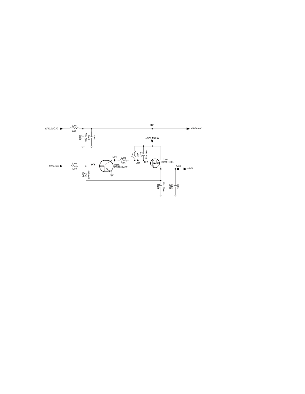
During start-up, it is important that the +1V8S_SW line comes up earlier than the
+3V3_MOJO line. In order to implement this, a delay circuit is added. TS7J05 switches
the MOSFET 7J04 “on” and “off”.
The diode (item 6J03) performs a short-circuit protection for the +3V3 output stage.
Page 88
Video processing
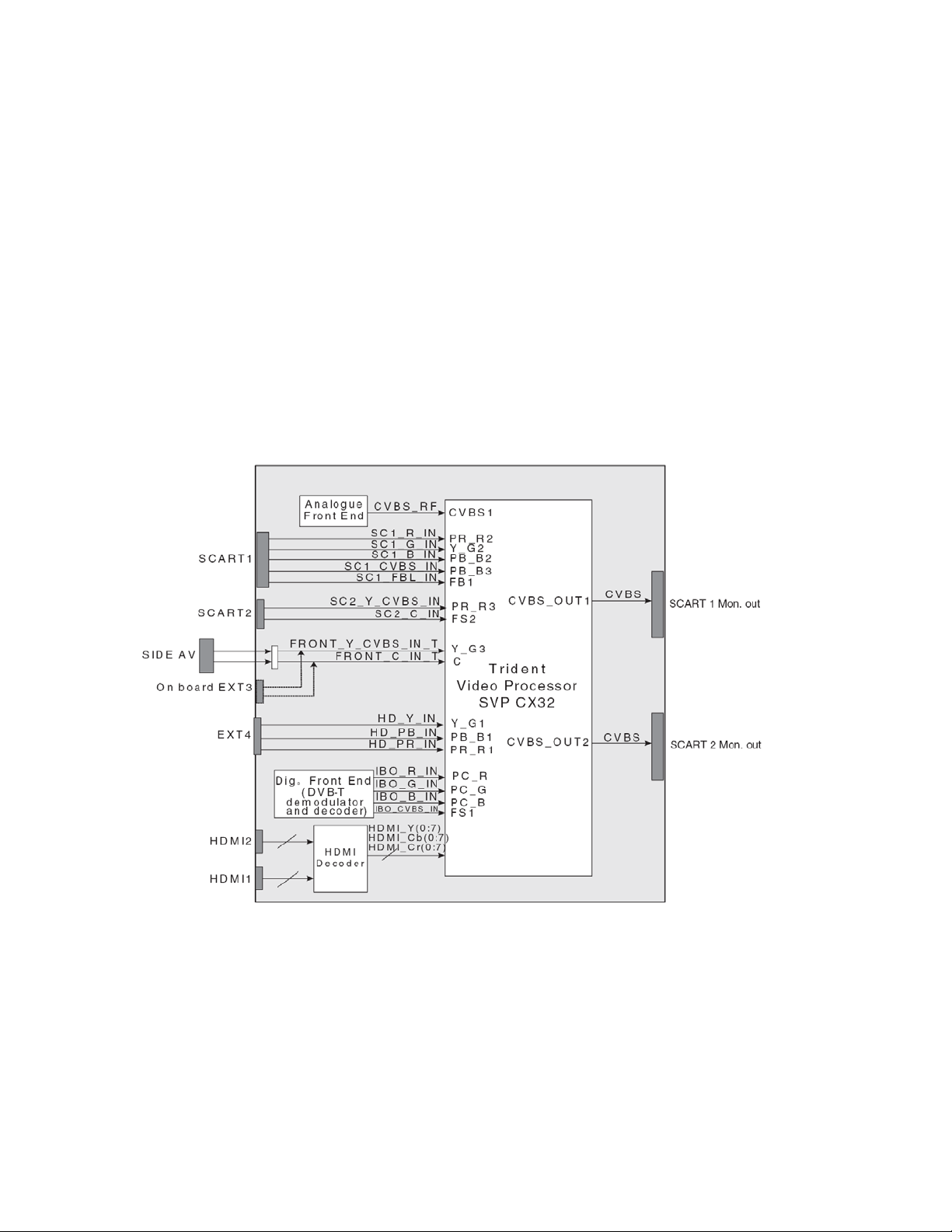
The video processing is completely handled by the Trident SVP
CX32 video processor features:
• CVBS-input for analogue signals.
• RGB-input for digital (DVB-T) signals.
• Motion and “edge-adaptive” de-interlacing.
• Integrated ADC.
• Built-in 8-bit LVDS transmitter.
• Colour stretch.
• Skin colour enhancement.
• 3D Digital Comb Video Decoder.
• Interlaced and Progressive Scan refresh.
• TeleText decoding.
• OSD and VBI/Closed Caption.
For analogue reception, a CVBS signal coming from the analogue front-end is fed to the
video processor via pin CVBS1. In the video processor is the multi standard video
processor (PAL/SECAM/NTSC).
During digital reception, the video signal coming from the MPEG decoder (MOJO) is fed
to the video processor via pins FS1, PC_RGB.
The video processor has also direct input for the SCART1 & 2 input, side AV, EXT4
(HD where applicable) and HDMI1 & 2 input.
Page 89
There are 2 CVBS outputs. SCART1 there is always the tuner signal (also for DVB-T
mode) and SCART2 is meant for recording (WYSIWYG). The source that is displayed,
is also available via SCART2 output.
Other output is LVDS for LCD or plasma display.
The Trident is supplied with the 3V3_SW and 1V8_SW (in standby the Trident is off). It
has its own oscillator of 14MHz connected to pins 204-205.
The reset for the Trident is on pin 86. This is from the uP.
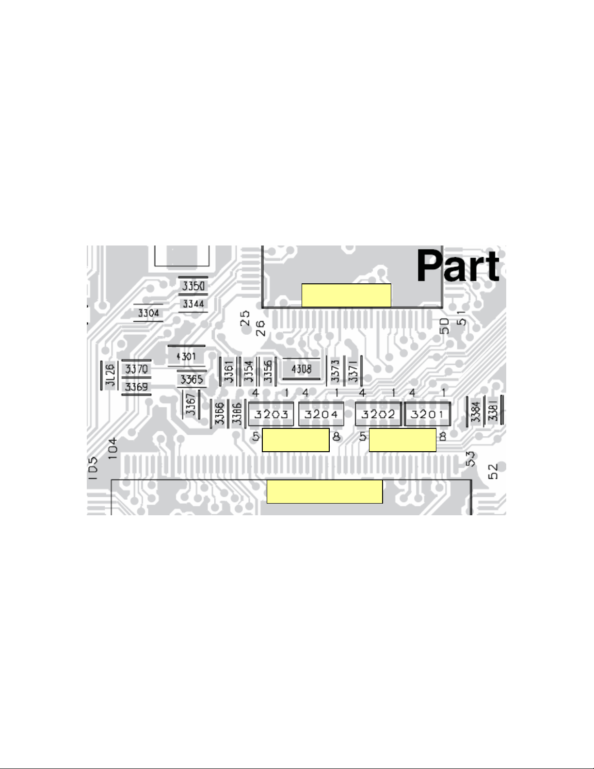
Communication between Trident and Renesas is via I2C bus and via parallel bus because
that is faster. There are series resistors on this bus and there it is possible to check for
activity on the bus.
uP
address data
Trident
The resistors are 3201, 3202, 3203 and 3204.
Two memories are connected to the video processor to store video content and for
storage of txt-pages.
Output from the Trident is LVDS, via filters to the screen. Depending on the used
display there can be different resolution.
i.e 1024x768 (PDP-panel) or 1366x768 (LCD-panel).
If 1080P display is used, then mostly the output from Trident is 1366x768. Except if the
input signal is 1080i, this is forwarded by the Trident. The 1080P panel takes care of the
de-interlacing.
Page 90
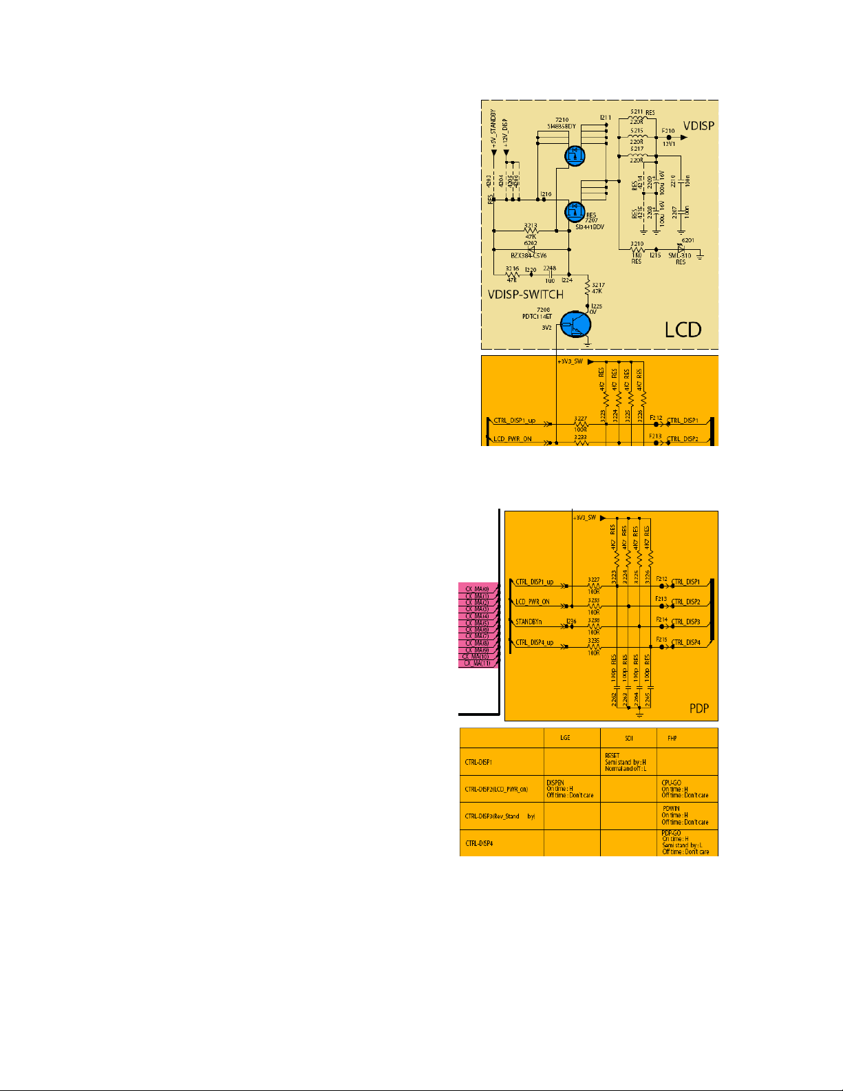
In this circuitry the 12V display is switched, this
voltage is used on the LVDS connector for the
logic board of the LCD or plasma panel.
LCD_PWR_ON is from the uP to switch on the
12V. There is a small delay in the switching of this
voltage and that generates a reset on the logic
board.
If F the FET 7210 has a leakage or short circuit
then the 12V is still present, but in some cases the
reset is not generated. This causes no picture on
the display.
LED 6201 is optional, not used in LC7.
There are 4 control lines for display, these are used for PDP-sets.
Depending on used brand (LGE, SDI or FHP),
different lines are used.
i.e. for SDI only CTRL-DISP1_up is used, at
pdp-side this line is named CTRL_DISP1. This
line is used to reset the logic board of the PDP.
Page 91
Audio processing
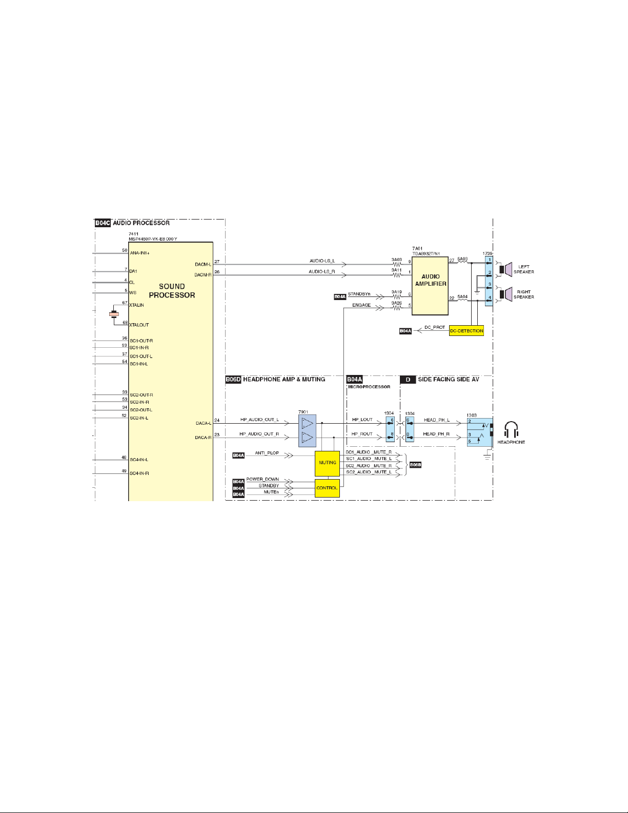
The audio processor used in LC7 is the MSP4450. All inputs are fed directly to the
MSP4450. Source select, FM demodulation, sound control is all in IC7411. The MSP4450
is supplied with 8V on pin 39. This 8V is derived from the +12V display. The MSP is also
supplied with 5V on pins 12,13 (digital) and 61,62 (analogue).
The IC makes use of its own crystal of 18MHz and needs a reset on pin 19 (low is reset),
this is controlled from the Renesas uP.
There are 2 outputs for SCART and on pins 26,27 is L/R for the amplifier.
At pins 23,24 is also variable level sound for headphone. If customer uses volume
control then both outputs are controlled together (there is no separate control for
headphone).
IC7A01 is the class D amplifier TDA8932T. It combines a good performance with a high
efficiency. Therefore no cooling plate required for this IC.
With pin 6 the amplifier is switched on, that is controlled by the uP. Pin 5 is used to
mute the amplifier via mute control circuitry.
In case of too high DC voltage for the loudspeakers, the protection is activated. The set
will switch off and via the led error 1 is indicated.
Page 92
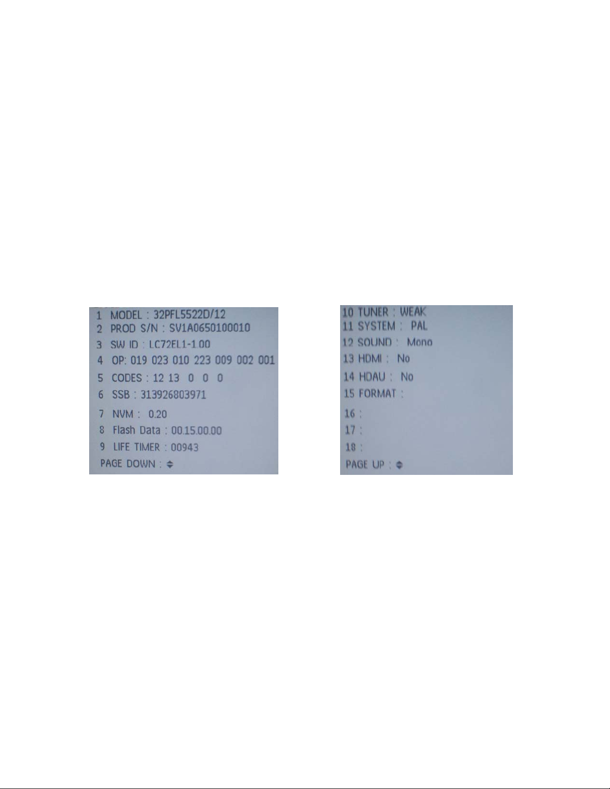
Service modes
Different service modes are used:
1. Customer service mode access via 1,2,3,6,5,4
2. Service default mode access via 0,6,2,5,9,6, menu
3. Service alignment mode access via 0,6,2,5,9,6, i+
4. Program display code 062598 menu xxx (xxx = the display code, see type plate)
Customer Service Mode (CSM) displays the status of the set. With this overview is
indicated which software is used in the set and for picture-sound settings. CSM in LC7 is
2 pages, with cursor up-down it is possible to navigate between the 2 pages.
This is in analogue mode:
Lines 1&2 there are type- and serial number displayed. If the display code is changed via
062598 menu xxx then these 2 lines have to be reprogrammed.
SW ID = software version.
LC7xEL is for LCD-sets
LC7xEP is for pdp-sets
LC7xELH is for 1080p sets
OP are the option codes (these are printed on the type plate)
CODES are the error codes
SSB is assembly number for the small signal board, to identify which board is in the set.
NVM there is indicated which version of nvm file is used
Flash data is part of the software for audio and picture quality settings
Life timer are the operation hours of the set
Tuner indicates quality of received signal
System is the detected colour system (PAL/SECAM/NTSC)
Sound mono, stereo, nicam
HDMI connected? Yes/no
Page 93
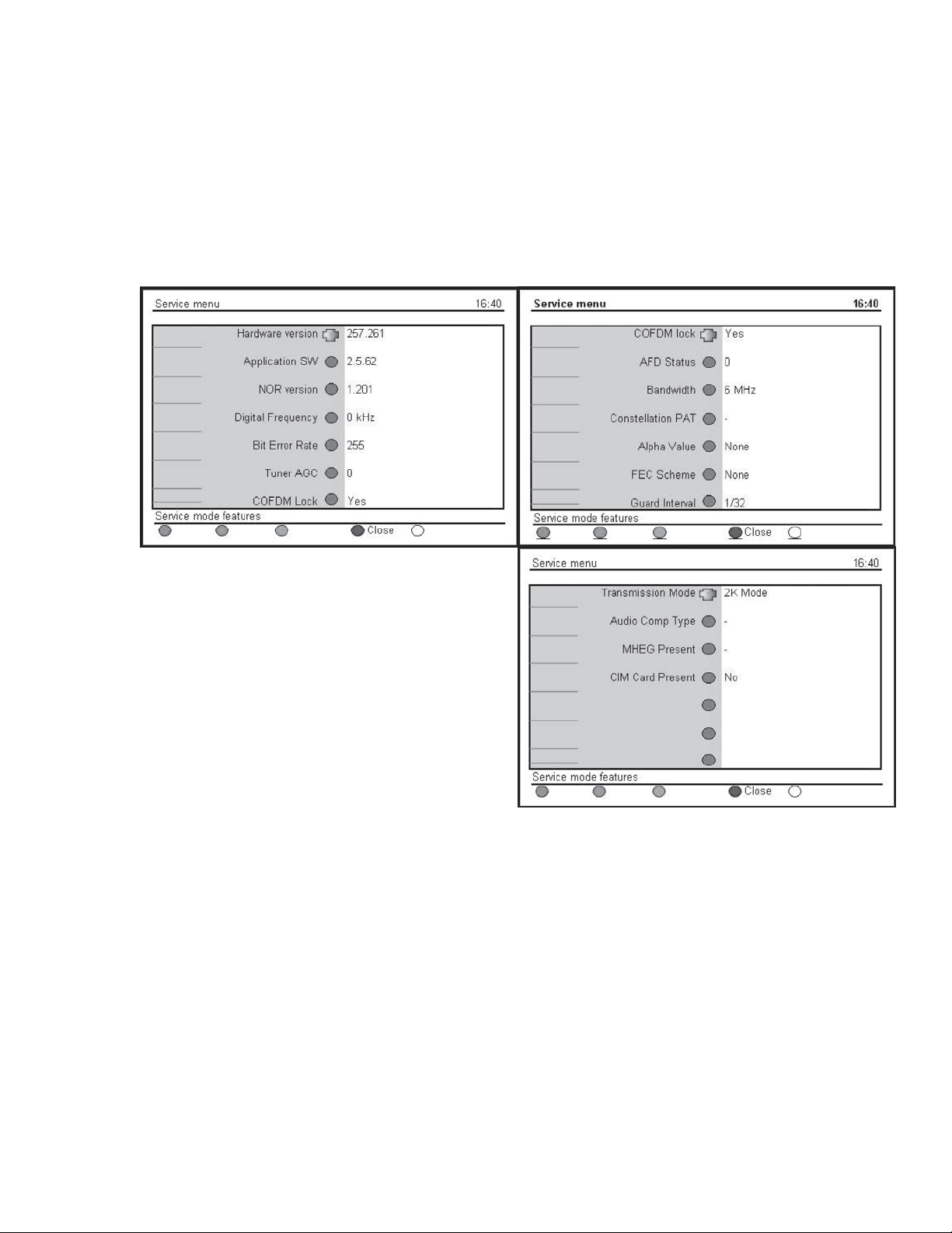
HDAU gives information about audio via HDMI
Format gives information about the video format (480i/480p/720p/1080i).
Lines 16 – 18 are optional.
Can be used to identify software version for 1080p panel or for ambilight.
There is also CSM in digital mode. This can also be entered via 1,2,3,6,5,4 or via the
digital menu. There go to information and then use this key sequence: Green Red
Yellow 9,7,5,9.
Hardware version identifies which hardware f
DVB-T is used in this set
Application SW is the software for DVB-T
NOR is the boot software for DVB-T
Digital frequency is the tuned freq.
Bit error rate gives impression for quality of
received signal
Bandwidth, mostly 8MHz is used
FEC, guard interval is transmitter dependent
Transmission mode 8k is used
MHEG is only used in UK at this moment
(more graphics in txt mode).
CIM Card present, indicates whether the CAM is detected. In case an encrypted channel
is not decoded, this can be used to check that the CAM is detected.
Service default mode
Via 062596 menu default mode is entered or short one of the “Service” jumpers on the
TV board during cold start. Then press the mains button.
Caution: Activating SDM by shorting “Service” jumpers will override the DC speaker
protection (error 1), the General I2C error (error 4), and the Trident video processor
error (error 5).
When doing this, the service-technician must know exactly what he is doing, as it could
damage the television set.
Tuning is 475,25 MHz.
or
Page 94
Set linear video and audio settings to 50%, but volume to 25%.
• All service-unfriendly modes (if present) are disabled:
– (Sleep) timer.
– Blue mute/Wall paper.
– Auto switch “off” (when there is no “ident” signal).
– Hotel or hospital mode.
– Child lock or parental lock
– Skipping, blanking of “Not favourite”, “Skipped” or “Locked” presets/channels.
– Automatic storing of Personal Preset or Last Status settings.
– Automatic user menu time-out (menu switches back/OFF automatically.
– Auto Volume levelling (AVL).
Menu explanation:
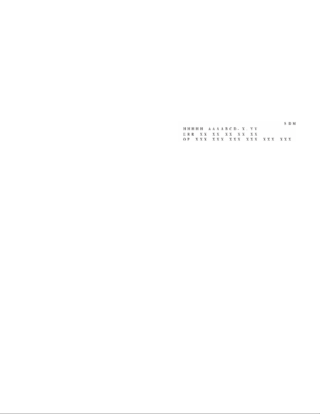
• HHHHH: Are the operating hours (in decimal).
• AAAABCD-X.YY: Software Identification, Version, and Cluster
• SDM: The character “SDM” to indicate that the TV set is in Service mode.
• ERR: Shows all errors detected since the last time the buffer was erased. Five errors
are possible.
• OP: Used to read-out the option bytes. See “Options” for a detailed description.
Service menu
062596 i+ to enter the service menu.
 Loading...