

Page 1
DP 6000 DIGITAL PAGING SYSTEM
INSTALLATION
INSTRUCTION
94
3922 988 58011 May 1999. Page 1
PS -Micro
Mobile Alarm Transmitters
LBB 6030/xx - LBB 6035/xx
Table of contents Page
Introduction ........................................................................ 1
Type Numbers ...................................................................3
Power supply .....................................................................3
Recommended battery types .............................................3
Replacing the batteries ......................................................3
Low Battery warning ..........................................................4
Battery charging .................................................................4
Operating Controls and alarm procedures .........................4
ON/OFF and Rack procedures .......................................... 4
Location Detection .............................................................5
Alarm procedures ...............................................................5
GS (Geprüfte Sicherheit) Approved Systems .................... 6
Installer Programming ........................................................6
Programming the addresses ..............................................7
Programming the Opcodes ................................................7
Description of Opcodes and their functions .......................8
Bleep patterns and LED indications....................................13
Diagnostics ........................................................................14
Field Coverage Test ...........................................................15
Application Guidelines. ......................................................15
Checkcalls ..........................................................................15
Transmission of location calls. ...........................................15
Storage racks .....................................................................16
Systems with speech .........................................................16
Inform the user ...................................................................16
1. I
NTRODUCTION
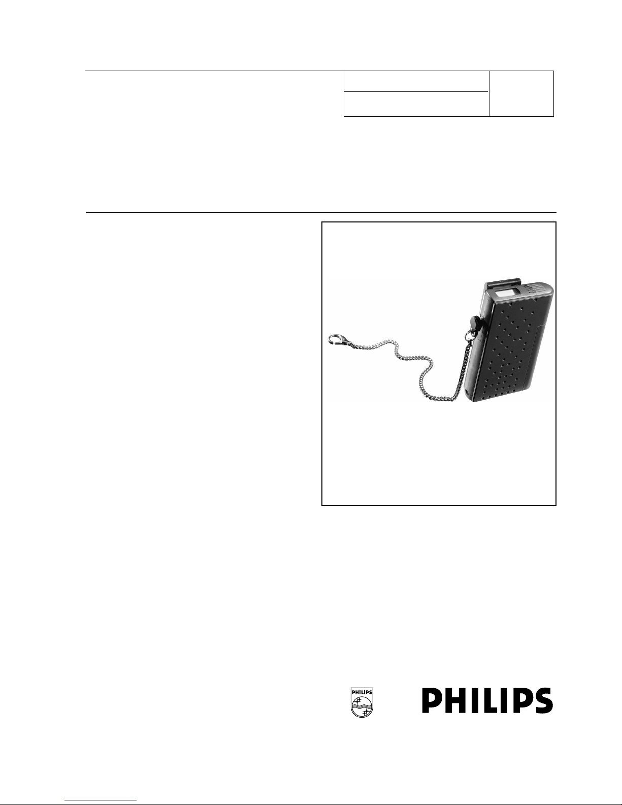
Intended for use in a Philips Personal Security system, the mobile alarm transmitters LBB 6030 - LBB 6035
provide a means of personal security for people working in potentially hazardous and dangerous locations.
The mobiles are capable of transmitting three types of calls to a central operator: Alarm calls, Check-in calls and Status
calls. Alarms calls are initiated by the mobile or b y the user in an alarm state. Such calls are initiated manually by the user
(Manual and Tear-out alarm) and automatically by the mobile when in a motionless/angled state (i.e. No-move and Not
vertical). Check-in calls are calls sent periodically to the central control to check the operational status of the mobile. Status calls are sent to indicate the status of the mobile, for example - Mobile IN or OUT of rack, Low battery indication (this
state is sent with each check-in call when low battery state is detected), OFF state transmitted after 1 hour of low battery
state.
Philips
Communication &
Security Systems
Page 2
DP 6000 DIGITAL PAGING SYSTEM INSTALLATION INSTRUCTION 94
May 1999. Page 2
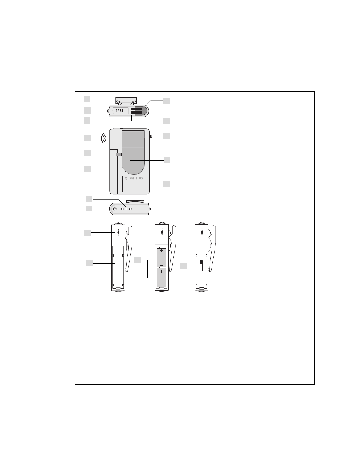
FIGURE 1. Layout PS-Micro mobile alarm transmitters
1
2
3
Key to Symbols
A Clip attachment
B Tear-out alarm socket
C Label placement (mobile ID address)
D Manual alarm/reset button
E LED indicator
F Sliding lock battery cover
G Battery cover
H Charging contacts
J Sticker placement
K Battery placement (see recommeded battery types)
L Programming/battery type sliding switch
M Battery cover locking screw
N Audible output
A
B
F
G
C
D
E
B
J
A
H
G
K
L
M
N
N
Page 3

INSTALLATION INSTRUCTION 94 DP 6000 DIGITAL PAGING SYSTEM
May 1999. Page 3
1.1 Type Numbers
This Installation Instruction covers the following type numbers:
LBB 6030/xx Mobile with Manual alarm
LBB 6031/xx Mobile with Manual alarm and location detection
LBB 6032/xx Mobile with Manual, Not-vertical and No-move alarm
LBB 6033/xx Mobile with Manual, Not-vertical, No-move alarm and location detection
LBB 6034/xx Mobile with Manual, Not-vertical, No-move and Tear-out alarm
LBB 6035/xx Mobile with Manual, Not-vertical, No-move, Tear-out alarm + location detection
/xx indicates the operational frequency of the mobile.
2. P
OWER
SUPPLY
The power to the mobiles is supplied by two LRI sized rechargeable or non-rechargeable batteries (fig. 1 K) or by a
single 3 V (non-rechargeable) lithium type Sanyo CR12600 SE battery. The choice between rechargeable and nonrechargeable batteries is made by a 3-position switch located inside the mobiles battery compartment (fig. 1L). See
also section 2.2.
WARNING: Never charge non-rechargeable batteries. Always place the programming switch in the middle position (2) (fig. 1L) for these kind of batteries.
2.1 Recommended battery types
Rechargeable: LBB 5931/02 or batteries with identical specification
Non-rechargeable batteries: Philips Alkaline type LR1 LBB 5312/00 or identical specification
Sanyo type CR12600 SE (1 per mobile)
NOTE: When placed in a Philips storage or charging rack type LBB 6150/00, /01, /02 and LBB 6152/00
the mobile receives its power from the charging/storage rack and not from the batteries, however batteries are needed for full operation in a rack.
2.2 Replacing the batteries
1. Opening the battery cover
• To open the battery cover, slide the battery cover lock (fig.1 F) in the direction of the clip.
• Use the special tool delivered with the mobile to unscrew the locking screw (fig. 1M) located underneath the
battery cover.
• Slide the battery cover (fig.1G) downwards
• Remove the battery(s)
2. Battery type selection
• Remove the battery(s) (fig.1K)
• Locate the 3-position slide switch at the rear of the battery housing (fig. 1L).
• Upper Position 1 = Programming/diagnostics mode only
• Middle Position 2 = Non rechargeable disposable batteries
• Lower Position 3 = Rechargeable batteries
3. Battery replacement
• Place the new battery(s) in the correct position (fig.1K) If rechargeable batteries are used ensure the batteries
are charged before using the mobile.
• Close and lock the battery cover.
NOTE: Nev er lea v e dead batteries in the mobile and ne v er lea v e batteries in the mobile during transportation.
Page 4

DP 6000 DIGITAL PAGING SYSTEM INSTALLATION INSTRUCTION 94
May 1999. Page 4
2.3 Low Battery warning
A visible and audible low battery warning facility (see section Bleep P attern and LED Indication Chapter 5) built-in to
the mobile indicates when the battery voltage drops below a certain level. This level for rechargeable batteries is
2.2 V*, for non-rechargeable batteries this level is 1.35 V*. The low battery state is transmitted to the central control
with each check-in call. When new batteries are placed in the mobile, the mobile will switch-ON and emit a confirmation bleep.
*The values given are measured under loaded conditions.
2.4 Battery charging
The mobile has three contacts (fig.1H) used for charging and programming the mobile when placed in its charging/
storage rack.
3. O
PERATING
C
ONTROLS
AND
ALARM
PROCEDURES
3.1 ON/OFF and Rack procedures
The Mobile has no ON/OFF s
witch. When the mobile is placed in a storage/charging rack in its normal operating
mode (i.e the battery/program switch is placed in position 2 (middle position) or 3 (lower position) (Fig.1L) it will emit
a confirmation bleep and generate a first status-call sequence with N-repetitions (opcode setting 1Q). After that it
will enter the normal status calls transmit mode. If the mobile receiv es (at any time) a reply-call from the central desk
via the rack interface, it will cancel its remaining repetitions and enter into the a state, were no more calls will be
transmitted until the mobile is removed from its storage/charging rack. The mobile however will still monitor the rack
interface. Should the central control desk send a request call for this mobile then the mobile will again begin its inrack check-in calls procedure.
All the sensors including the location receiver (if placed) are functionaly disabled once the mobile is placed in its
storage/charging rack. The last two received locations will remain stored. When removed from its storage/charging
rack, the mobile will begin a status call sequence with the in_ rack bit set to 0 and the ON bit set to 1.
NOTE: When the mobile is placed in a single storage rack LBB 6152/00, the mobile acts as if it was placed in a
standard storage rack (provide absence indication etc..).
If the mobile is placed in a storage/charging rack in an alarm state, it will reset the alarm state and transmit a status-
call with the reset alarm status. If after 5 seconds the mobile is still in the storage/charging rac k it will restart the call
sequence and transmit a call (N-times repeated) with the reset alarm status and the rack bit set. If however the
mobile is removed from the storage/charging rack within 5 seconds of placing it in its rack, it will complete its resetalarm calls repetition without changes, as though it hadn’t been placed in a storage/charging rack.
When the mobile is placed in a storage/charging rack in a pre-alarm state, this state will be reset. In this case if the
mobile is still in the rack after 5 seconds it will begin a status-call sequence with the rack bit set. If however it is taken
out of its rack within 5 seconds it will only reset the pre-alarm state without starting an in-rack status call sequence.
When the battery/program switch is in the ‘Program’ position and the mobile is powered by batteries, it will emit a
confirmation bleep and enter into the ‘Diagnostic_Standby’ mode. In this mode no calls will be transmitted and the
mobile will only react when the Manual alarm button is pressed, or when placed in a storage/charging rack. For a
description of the diagnostic mode refer to Chapter 6.
When the battery/program switch is in the ‘Program’ position and the mobile is in a storage/charging rack (with or
without batteries) it will emit a confirmation bleep and enter into the ‘Program’ mode. In this mode when the manual
alarm button is pressed for more than 2 seconds the mobile will reset all its settings to default and generate a ‘Program’ bleep on completion and return back to the ‘Program’ mode. For a description of the programming refer to
Chapter 4.
Page 5

INSTALLATION INSTRUCTION 94 DP 6000 DIGITAL PAGING SYSTEM
May 1999. Page 5
NOTE: Before (re)progr amming the mobiles in an activ e system, the installer must ‘disable’ the mobile in
the central control desk to prevent a central alarm state, because the desk will not receive any check-in
calls from the mobile.
When taken out of the rack after programming, the program switch should be returned to its normal position
(rechargeable or no-rechargeable batteries). After replacing the battery(s) the mobile will switch ON and gener ate a
confirmation bleep and begin a status call sequence (with N repetitions) with the rack-bit off. On completion the
mobile will proceed with normal check-in calls until its status changes.
When a location receiver is installed , the default ‘last’ and ‘bef ore last’ location codes in memory will be ‘FFFFF’ until
valid location codes are received.
If the mobile is placed in a rack without a ‘Tear-out’ connector, and then removed again, the ‘Tear-out’ function will
only be activated after the connector is placed. This procedure is not applicable for GS approved systems.
3.2 Location Detection
The last two different locations visited by the mobile are kept in the memory. The locations of the mobile are transmitted to the central with each check-in/status call and with each alarm call. The mobile can be programmed in one
of the following ways to transmit location information:
1. Locations are transmitted with check-in and alarm calls only (default). This method is recommended due to the
reduction of calls in the system.
2. Locations are always transmitted instantly on the detection of a new location. This method is not recommended
due to the large number of calls generated in systems employing a large number of mobiles and location transmitters.
3. If the mobile has NOT been programmed to transmit the location instantly, a digit can be programmed in to the
mobile opcode to identify whether the location of the mobile should be transmitted instantly or not. This digit
should be identical to the first address digit programmed in the location transmitter. This method gives numerous
possibilities (e.g. guard tour).
4. Independant of the mobile programming, if the location transmitters address begins with ‘F’, the mobile will always
transmit location information instantly when passing the relevant transmitter. Furthermore depending on the
value of the second address digit of the location transmitter the mobile can give an audible indication to the user
(for additional information see section 8.2 Transmission of location calls).
NOTE: When the mobile is in an alarm state it will always transmit all new locations directly to the central indepen-
dent of how the mobile is programmed .
3.3 Alarm procedures
3.3.1 Manual Alarm button
Press the manual alarm button for at least two second to start an alarm procedure. The mobile will emit an alarm
bleep and its LED will flash. To reset the alarm see 3.3.5 ‘RESET’ alarm procedures.
NOTE: The alarm tone of manual/tear-out alarm can be programmed to be enabled or disabled.
3.3.2 No-Move / Not Vertical Alarm.
No-Move and Not Vertical alarms and pre-alarms are generated automatically when the mobile is in any of the following situations:
Page 6

DP 6000 DIGITAL PAGING SYSTEM INSTALLATION INSTRUCTION 94
May 1999. Page 6
1. The mobile remains motionless (No-move) and does not move for a pre-determined time.
2. The mobile remains motionless at an angle of more than 75 degrees from vertical (Not vertical) for a pre-deter-
mined time (in this case the mobile is programmed so that No-move and Not-vertical are coupled and both
alarms should be enabled).
3. The mobile remains at an angle of more than 75 degrees from vertical for a pre-determined duration.
To reset either of the alarms move the mobile from its stationary position or follow one of the RESET procedures
(see 3.3.5 RESET alarm procedures).
3.3.3 Tear-out Alarm
The tear-out alarm and pre-alarm is generated automatically once the tear-out plug is removed from its position. The
alarm can be programmed as a silent alarm or with an audible bleep. The alarm can be reset by replacing the tearout plug (not valid for GS approved systems) or by placing the mobile in to its storage/charging rack.
3.3.4 Pre-alarms
To indicate that a No-move, Not-verical or Tear-out alarm is about to be transmitted, the mobile can be programmed
to emit a pre-alarm (cricketed-tone). During this pre-alarm state, an alarm can be reset by either moving the mobile
from its stationary position, replacing its tear-out plug, or by pressing the alarm button for a short period. Using this
procedure reduces the possibility of false alarms.
3.3.5 RESET alarm procedures
To reset an alarm, proceed in one of the following ways (not valid for Tear-out alarm see 3.3.3):
- Press the Alarm/Reset button once to reset the audible alarm bleep (the alarm remains active as a silent
alarm). Press the Alarm/Reset button for the second time to reset the active alarm. If the opcode is programmed for a silent alarm the alarm can be reset by pressing the Alarm/Reset button once only (<1 second).
- Place the mobile in its charging/storage rack (for GS appro v ed systems this method is the only method to reset
an alarm).
NOTE: During the audible alarm bleep the no move sensor is NOT ACTIVE.
3.4 GS (Geprüfte Sicherheit) Approved Systems
The mobiles can be used in systems with or without GS approval. If the GS mode is enabled in the opcode all the
alarms that are active in the mobile require testing when a mobile is taken out of its storage rack. Mobile also needs
to be tested after 23 hours of continuous operation and when the batteries have been changed. This test should be
performed to check that the alarm functions of the mobile are functioning correctly. In GS mode the central control
should receive a check-in call at least every 10 minutes from each operational mobile in the system. Refer to the
LBB 6509 Software manual for operational procedures.
4. I
NSTALLER
P
ROGRAMMING
The settings of the mobile can be programmed by an alphadesk PC or other compatible DP6000 encoder connected
via the DP6000 bus-line to the mobiles storage/charging rack LBB 6150/00 or LBB 6150/01. The mobile must be
placed in the programming mode. To place the mobile in its programming mode place the 3-position slide switch
(fig.1L) to its upper position (1) and then place it in its storage/charging rack. The mobile receives via the DP6000
encoder programming information via the contacts on the rack. The slave rack (LBB 6150/00) should be connected
to the DP6000 bus line via the Master charging rack LBB 6150/01.
The programmed data will remain stored in the mobile until it is overwritten or set to default. Programming should be
carried out by the installer or system manager responsible for allocating mobile addresses.
Page 7

INSTALLATION INSTRUCTION 94 DP 6000 DIGITAL PAGING SYSTEM
May 1999. Page 7
Initializing the mobile
1. Place the mobile in its storage/charging rack (ensure the switch is set to the programming position).
2. Press the ‘Manual’ alarm button for more than 2 seconds.
3. The mobile will generate a program bleep after initialization and all the setting will be set to default values.
4. When the ‘Manual’ alarm button is not pressed, all the old settings will remain and can be overwritten by the
relevant data string.
5. Each time an address/opcode is programmed a bleep tone is generated by the mobile (only with batteries fitted).
4.1 Programming the addresses
4.1.1 Via the Alphadesk
1. Enter the ‘Edit’ menu in the user program
2. Select the ‘Receiver’ menu item
3. Select ‘program Addresses’
4. Enter the mobile ‘Address’ number 1 and Address digits
4.1.2 Via the LBB 580x desk
1. Press the program key followed by the ‘0’ key. The desk is now in the programming mode.
2. The desk display shows RAD:
3. Enter the address as follows: 1 A
3
A
2
A
1
A
0
(A
x
= address digit)
4.2 Programming the Opcodes
4.2.1 Via a PC fitted with the LBB 6000 card:
To program the functions of the mobile, 2 different operation codes (Opcodes) are used. Each Opcode consists of 6
Hex digits where each digit determines one or a group of functions.
Each digit of the operation code is represented by the letters P, Q, R, S, T, U, and the function or group of functions
assigned to each digit is described in chapter 4.3:
1. Enter the ‘Edit’ menu in the user program
2. Select the ‘receiver’ menu item
3. Select ‘program opcodes’
4. Enter the ‘opcode’ number M
5. M = 3 if operation code 1 is to be programmed in the mobile
6. M = 4 if operation code 2 is to be programmed in the mobile
7. Enter the opcode (HEX value): PQRSTU
4.2.2 Via the LBB 580x desk
1. Press the program key followed by the Opcode number M
M = 3 if operation code 1 is programmed in the mobile
M = 4 if operation code 2 is programmed in the mobile
2. Enter the opcode hexadecimal value: P Q R S T U
(for the description of the opcodes and their functions see page 8).
Page 8

DP 6000 DIGITAL PAGING SYSTEM INSTALLATION INSTRUCTION 94
May 1999. Page 8
4.3 Description of Opcodes and their functions
4.3.1 OPCODE 1
(P) Interval Timing between Check calls
Opcode 1 (P) sets the interval timing between check calls. The digit entered in this opcode is dependant on the
number of mobiles used in the system. The value entered should be according to the value given in the ‘PS-Micro
Scanning Repeat Assistant’ located under ‘Channels’ in the PS6000 Editor of the LBB 6509 or LBB 6507 software
package.
* The 4.5 second timing between check calls is only meant for field coverage tests (see Chapter 7).
To avoid collision of mobiles that are quasi-synchronized transmitting calls, the check call timing (according table 1)
is implemented as a typical timing with a randomized deviation of ±2 seconds. So a check call every 60 seconds will
be a randomized time of between 58 and 62 seconds with a mean-time of 60 seconds. This randomizing will be
omitted at the field-coverage test (setting 4.5 sec.). The default timings (check call every 2 minutes and 3 call repetitions (Opcode setting 1Q) are suitable for a moderate system with approx. 15 mobiles.
(Q) Call Repetition
Opcode 1(Q) sets the number of times the alarm and status-call is repeated (0 - 15 times). When N = 0,1, 2 or 3 the
call will be repeated three times. The timing of the call repetition is dependent on the address that is programmed in
the mobile. This is done to prevent collision with alarm and location calls initiated simultaneously. This value is also
given in the PS-Micro Scanning Repeat Assistant LBB 6509 or LBB 6507 software package.
(R) Not Used
Table 1: Timing between check-in calls
Digit
(HEX 0 - F)
check-in /status call
0 none
1 4.5 sec. (*)
2 30 sec.
3 45 sec.
4 60 sec.
5 90 sec.
6 2 min.
7 3 min.
8 5 min.
9 10 min.
A 15 min.
B 30 min.
C 1 hour
D 2 hour
E 3 hour
F 4 hour
Page 9

INSTALLATION INSTRUCTION 94 DP 6000 DIGITAL PAGING SYSTEM
May 1999. Page 9
(S) Not Used
(T) Location detection/ System ID
Bit 3: Location detection enable/disable (1 = enable, 0 = disabled)
Bit 2: Location transmission mode. Location transmission from the mobile to the central control desk can be set
to take place directly after the mobile has received a new location, or only when the mobile transmits a
check-in call to the control desk. The reason for this programmable option is to provide the installer with the
possibility to avoid too many uncontrolled location calls in very busy systems. In systems using many
mobiles and/or location transmitters it is advisable to set the transmission of locations when the mobile
transmits a check-in call.
(1 = direct transmit, 0 = only with check-in calls)
Bit 1: System ID (range HEX 0 - HEX 3) The System identity is transmitted with the ‘mode word’ in the DP6000
code to separate two neighbouring systems which are operated on the same frequency. This feature can
only be used in future systems when this function has also been implememted in the central desk. At
present the system ID digit should be set to ‘0’.
Bit 0: System ID (range HEX 0 - HEX 3) (see Bit 1).
(U) Location digit
Enter location digit (range 0 - F (Hex)) (refer to Chapter 3.2 for a description).
4.3.2 OPCODES 2
(P) Turn on time No-move/Not-vertical alarm
Opcode digit 2(P) sets the turn on time of the No-move/Not-vertical pre-alarm in steps of 5 seconds. The mobile
should detect the No-move / Not-vertical status during the time set before it enters in to the pre-alarm status, range
0 - 75 seconds in steps of 5 seconds. Enter digits (Hex) 0 - F.
(Q) Pre-alarm time No-move/Not-vertical alarm
Opcode digit 2(Q) sets the pre-alarm time of the No-move/Not-vertical alarm in steps of 5 seconds. The mobile
should go through a prealarm status before the real alarm is transmitted to the central control unit , range 0 - 75 seconds in steps of 5 seconds. Enter digits (Hex) 0 - F.
(R) Pre-alarm time Tear-out alarm
Opcode digit 2(R) sets the time a prealarm status should occur before a real alarm is transmitted to the central control, range 0 - 75 seconds in steps of 5 seconds. Enter digits (Hex) 0 - F.
(S) Options mobile mode
Bit 3: GS procedure enable/disable (1 = enabled, 0 = disabled)
Bit 2: No-move coupled with Not-vertical alarm: If enabled, only a No-mov e alarm is generated if a No-mov e and
a Not-vertical alarm situation is present (1 = coupled, 0 = not coupled)
Bit 1: Not used
Bit 0: Not used
(T) Alarm settings
Bit 3: No-move alarm enable/disable (1 = enabled, 0 = disabled)
Bit 2: Not-vertical alarm enable/disable (1 = enabled, 0 = disabled)
Bit 1: Tear out enable/disable (1 = enabled, 0 = disabled)
Bit 0: Not used
(U) Silent settings
Bit 3: Manual alarm silent: (1 = silent, 0 = with audible bleep signal). Manual alarm with audible bleep signal to
enable rescuers to locate the individual at risk.
Bit 2: Tear-out alarm silent (1 = silent)
Bit 1: Not used
Bit 0: Not used
Page 10

DP 6000 DIGITAL PAGING SYSTEM INSTALLATION INSTRUCTION 94
May 1999. Page 10
OPERATION CODE 1
Interval timing between check-in calls
Range (0 - F) Refer to Table 1
Call repetition ‘N’ (No. of times an alarm/status call is
repeated)
N = No of call repetitions (Range 0 - F)
Not used
Not used
- Location detection enable (0 = disabled, 8 = enabled)
- Location mode (4 = direct transmission, 0 = transmission only with check-in calls)
- System identity (range HEX 0 - HEX 3)
(future use)
Location digit (range 0 - F)
=
P
6
=
P
=
Q
2
=
Q
=
R
0
=
R
0
=
S
0
=
S
0
0
0
0
0
=
T
0=
=
T
Options
8
4
2
1
=
U
15
=
U
= HEX F
Default settings
Page 11

INSTALLATION INSTRUCTION 94 DP 6000 DIGITAL PAGING SYSTEM
May 1999. Page 11
OPERATION CODE 2
Turn on time No-move/Not vertical
(0 - F, steps of 5 seconds)
Pre-alarm time, no-move / Not-vertical alarm
(0 - F, steps of 5 second
Pre-alarm time Tear-out alarm
(0 - F, steps of 5 seconds)
- GS procedure enabled (0 = Off, 8 = enabled)
- No-move coupled with Not-vertical
(0 = not coupled, 4 = coupled)
- Not used
- Not used
- No-move alarm (8 = enabled, 0 = disabled)
- Not-vertical alarm (4 = enabled, 0 = disabled)
- Tear-out (2 = enabled, 0 = disabled)
- Not used
- Manual alarm (0 = loud, 8 = silent)
- Tear-out (0 = loud, 4 = silent)
- Not used
- Not used
=
P
6
=
P
=
Q
6
=
Q
=
R
1
=
R
0
4
0
0
=
S
4
=
=
S
Options
8
4
2
1
0
0
0
0
=
T
0
=
=
T
Options
8
4
2
1
0
0
0
0
=
U
0
=
=
U
Options
8
4
2
1
Default settings
Page 12

DP 6000 DIGITAL PAGING SYSTEM INSTALLATION INSTRUCTION 94
May 1999. Page 12
TOTAL VALUES OF OPCODES INSTALLED
OPCODE 1
OPCODE 2
QPRSTU
26 000F
66 1400
Default:
Default:
Page 13
INSTALLATION INSTRUCTION 94 DP 6000 DIGITAL PAGING SYSTEM
May 1999. Page 13
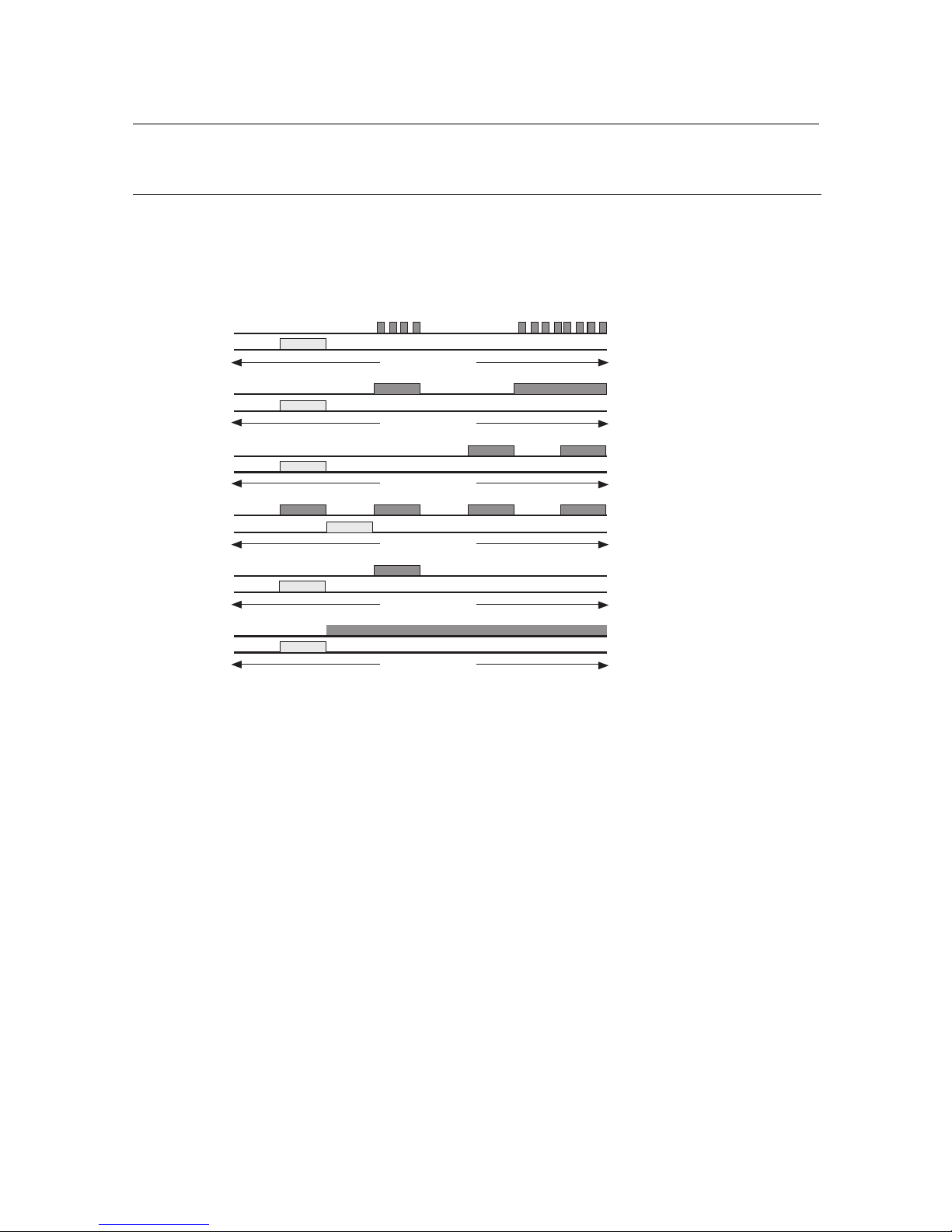
5. BLEEP PATTERNS AND LED INDICATIONS
The following LED/bleep patterns are available:
* If the mobile detects an error in its transmission output the error bleep is audible
Bleep
8*133 msec.
8*133 msec.
8*33 msec.
8*33 msec.
8*33 msec.
8*133 msec.
PRE-ALARM BLEEP (cricketed bleep)
ALARM
LOW BATTERY
ERROR
CONFIRM BLEEP
PROGRAMMING
LED
Bleep
LED
Bleep
LED
Bleep
LED
Bleep
LED
Bleep
LED
*
Until reset
Until reset
Every 60 seconds
Until reset
One time
One time
Page 14

DP 6000 DIGITAL PAGING SYSTEM INSTALLATION INSTRUCTION 94
May 1999. Page 14
6. D
IAGNOSTICS
To place the mobile in its diagnostic mode proceed as follows:
1. Remove the batteries from the mobile
2. Place the sliding battery/program switch to the diagnostic position (position 1 (Fig.1L)).
3. Replace the batteries (a confirmation bleep should be heard), the mobile is now in its diagnostic standby mode.
4. Press the manual alarm b utton for less than 2 seconds (2 x confirmation bleeps) to enter the mobile into the Location Monitor mode. In this mode , after reception of e v ery valid location code, the mobile generates a confirmation
bleep. If no location receiver is installed in the mobile nothing will happen.
5. Press the manual alarm button again for less than 2 seconds (3 x confirmation bleeps), the mobile will enter into
its Sensor Test mode. In this mode the T ear-out, No-mo ve and Not-vertical sensors can be tested (if installed) as
follows:
• 1 second after removing the tear-out plug the mobile will generate a confirmation bleep and LED indication.
After replacing the tear-out plug into its socket this test can be repeated.
• 5 seconds after being in the No-move state, the mobile will illuminate the LED. Moving the mobile from its sta-
tionary position will restart the test sequence.
• 1 second after being in the Not-vertical state, the mobile will generate a pre-alarm bleep. Moving the mobile
upright will restart the test sequence.
NOTE: The coupling setting of the No-move/Not-vertical will be ignored. Therefore when laid flat, the
mobile in its Not-vertical state will generate a pre-alarm bleep after 1 second and in its No-move state will
illuminate the LED after ±5 seconds.
6. Press the manual alarm button again for the third time, for less than 2 seconds (4 x confirmation bleeps), the
mobile enters the Transmitter Test mode. In this mode the transmitter will be ON continuously, modulated by a
DP6000 “F” code. Using this method the frequency, deviation and transmitted power can be observed. The LED
illuminates constantly during this test.
7. Press the manual alarm button again for the fourth time for less than 2 seconds (5 x confirmation bleeps). The
mobile will enter the “Transmit address and opcodes” mode. In this mode the mobile transmits a call periodically
accompanied with an LED flash with its own address and the two opcodes in the alpha message as follows:
- address = address set in the alarm transmitter
- codinf = 0
- modeword
- alpha message $3FP
1Q1R1S1T1U1
$4FP2Q2R2S2 T2 U
2
This information can be viewed on the monitor of the alphadesk after setting “Display calls” enabled in the
system editor of the LBB 6000.
Example:
A mobile with address 0001 and opcode setting as default will transmit a call with address 0001 and the alpha
message 3F62000F 4F661400.
8. Press the manual alarm button again f or the fifth time (1 x confirmation bleep) to place the mobile back in the diagnostic standby mode. When placed in a storage/charging rack while in the diagnostic mode, the mobile will enter
into the programming mode. If the alarm button is pressed for longer than 2 seconds during any test, the mobile
re-enters the diagnostic standby mode (1 x confirmation bleep). The mobile will not transmit any check-in/status
or alarm-calls while in the diagnostic standby mode.
Opcode 1 Opcode 2
Page 15

INSTALLATION INSTRUCTION 94 DP 6000 DIGITAL PAGING SYSTEM
May 1999. Page 15
7. FIELD COVERAGE TEST
When the time interval for check-in calls for a mobile is set to 4.5 seconds (opcode setting = 1) the alphadesk will
respond to these calls with an acknowledge call via the paging line to a pager with the the same address as the
mobile alarm transmitter and as alpha message the address digits of the two locations which were originally sent by
the mobile alarm transmitter.
This feature can be used to perform a field cover age test by walking around the site with a mobile alarm transmitter
and a paging receiver. The paging receiver (or transceiver) can be set to the monitor mode or it should be programmed on the same address as the mobile alarm transmitter.
8. APPLICATION GUIDELINES.
8.1 Checkcalls
Always use the Scanning repeat assistant in the LBB6509 software module to determine the timing of the check-in
calls and the number of repeats of the alarms and directly transmitted location calls. Independent of the outcome of
the calculation of this program the minimum number of repeats that the mobile will transmit will be 3.
To minimise the probability of collisions between calls always enter the repeat time for as long as possible. So
always start with a proposal for the maximum repeat time. Only when the customer insists on a shorter failure detect
time should you decrease the repeat time in the mobile. Never use a shorter repeat time than the result produced
from the calculation of the ‘Scanning Repeat assistant’.
If possible don’t program all mobiles in the system for the shortest repeat time necessary. Due to different working
practices it may not be necessary for all mobile in the system to have equal failure detect times.
The above will improve system occupation making the system less busy. If system occupation is kept as low as possible, the probability for collisions is kept to a minimum.
If the system consists of a mix of different types of PS-mobiles (e.g. PS-Micro, PS-pagers and PS-transceivers)
always make the calculation with the total number of mobiles and the shortest failure detect time that is used.
8.2 Transmission of location calls.
The preferred setting for the transmission of location calls is with chec k-in calls only (progr am setting of opcode digit
1T, second bit set to 0). In case of an alarm, the mobile will always send its last two locations with the alarm call. As
long as the mobile stays in alarm condition it will send newly received locations directly to the central which leads to
an update in the alarm text screen (not of the graphical screen). This mak es it possib le to k eep trac k of a person that
has raised an alarm.
If the alarm call is activated, the new locations will also be transmitted to the assigned paging receiver(s) address
programmed to receive the rerouted alarm call.
If direct transmission of locations is required in a system, minimise the number of mobiles and the number of locations with which this function is performed. The following possibilities are available to achieve this:
Page 16

DP 6000 DIGITAL PAGING SYSTEM INSTALLATION INSTRUCTION 94
May 1999. Page 16
8.2.1 Location transmitter addresses starting with F.
Independent of the programming of the mobile this location will be transmitted directly to the central.
Furthermore, depending on the value of the second address digit of the location transmitter the mobile can give an
audible indication to the user as follows:
Location address starts with FF.
The mobile will emit a bleep signal until it is placed in a storage rack and the location is sent directly to the central.
NOTE: During the bleep signal the no move sensor is NOT ACTIVE.
Location address starts with FE.
The mobile will emit a bleep signal until it is reset by a short press on the Alarm/Reset button and the location is sent
directly to the central.
NOTE: During the bleep signal the no move sensor is NOT ACTIVE.
Location address starts with FD.
The mobile will give an attention bleep to the user (One short bleep signal) and the location is sent directly to the
central.
Location address starts with F0 to FC.
The mobile will transmit the location directly to the central without drawing the attention of the mobile user.
NOTE: Once the audible indication has been reset after passing a relevant location transmitter, this signal will not
be initiated again for as long as this location address is still in the memory of the mobile. Therefore it is advisable to
place a location transmitter with a different address in the area of the storage racks to refresh the location memory
of the mobile before it is stored in its rack.
8.2.2 Direct transmission of location dependant on first location address digit.
If the location address does not begin with F the mobile can be programmed (opcode 1U) to transmit a certain location directly if the location address starts with the digit that is programmed here. In this way the installer can determine that certain locations are only transmitted directly by certain mobiles (e.g. for guard tour applications).
The mobile will transmit the location directly to the central without alerting the mobile user.
8.3 Storage racks
Try to prevent placing more than one mobile in or out of the storage rack simultaneously, this may lead to collision of
the in/out rack call.
Preferably, use storage racks that are connected to the central via the paging line. When a mobile is placed in a rack
it will transmit an in-rack call to the central which will be acknowledged by the central via the DP6000 line. In this
case the mobile will detect this response call via its rack contacts and it will stop sending calls until it is taken out of
the rack again, or until it is called again by the central via the paging line (which is detected again via the rack contacts of the mobile).
This will limit the number of calls in the system and reduce the chance of collisions in the system.
8.4 Systems with speech
In systems where talk back speech is used, it is preferred to hav e the talk bac k on a diff erent frequency channel and
on separate talk-back lines.
Page 17

INSTALLATION INSTRUCTION 94 DP 6000 DIGITAL PAGING SYSTEM
May 1999. Page 17
If a different frequency channel is not possible the talk back speech will be disturbed by random calls from the PSMicro mobiles and the speech signal may disturb the calls from these mobiles. Therefore always minimise the use of
talk-back speech (e.g. only use speech in alarm situations or use the PS-Micro mobiles during the day and the
transceiver during the night).
8.5 Inform the user
Always give proper instructions to the users of the mobiles as well as to the users of the central. Ensure that these
instructions are included in the delivery conditions. It is essential that the users know what they can and what they
cannot expect from the system.
It is very easy to create customer specific ‘action guidance pages’ (help text in case of alarm) in the alphadesk P.C.
software. This action guidance text can inform the central operator how to deal with incoming alarms.
 Loading...