

Philips KV-S5055C Service Manual
Order Number KM71005571CE
Category Number G14
High Speed Color Scanner
Model No. KV-S5055C
© Panasonic System Networks Co., Ltd. 2010
Unauthorized copying and distribution is a violation
of law.

TABLE OF CONTENTS
PAG E PAG E
1 GENERAL PRECAUTIONS -------------------------------------4
1.1. Safety Precautions-----------------------------------------4
1.2. Electrical Tests ----------------------------------------------4
1.3. Standard for Repair Service -----------------------------4
1.4. For Service Technicians ----------------------------------5
1.5. About Lead Free Solder (PbF: Pb free) --------------5
1.6. About RoHS -------------------------------------------------5
2 SPECIFICATIONS -------------------------------------------------6
3 COMPONENT IDENTIFICATION ------------------------------8
3.1. Main Part Names and Locations ----------------------8
3.2. Control Panel---------------------------------------------- 10
4INSTALLATION--------------------------------------------------- 11
4.1. Minimum Space Requirements ----------------------- 11
4.2. Included Accessories------------------------------------ 12
4.3. Installing Double-feed Prevention Roller ----------- 13
4.4. When Scanning Documents of Different
Sizes Together --------------------------------------------15
4.5. DIMM Module Extension ------------------------------- 17
4.6. Installing DIMM Modules ------------------------------- 19
4.7. Connecting the Scanner to a Personal
Computer--------------------------------------------------- 20
4.8. System Requirements ---------------------------------- 21
4.9. Installing the Driver and Software-------------------- 21
5 SECTIONAL VIEW----------------------------------------------- 22
5.1. Bottom Block ----------------------------------------------22
5.2. Back Block ------------------------------------------------- 23
5.3. Upper Block------------------------------------------------ 24
5.4. Lower Block------------------------------------------------ 25
6 MECHANICAL FUNCTION ------------------------------------ 27
6.1. Paper Feed Mechanism (Auto) ----------------------- 27
6.2. Paper Feed Mechanism (Manual) ------------------- 29
6.3. Paper Feed Operation ----------------------------------30
6.4. Glass Cleaning Mechanism (Auto) ------------------ 32
6.5. Detecting Bent Paper ----------------------------------- 32
7 MAINTENANCE -------------------------------------------------- 33
7.1. Maintenance Chart--------------------------------------- 33
7.2. Cleaning ---------------------------------------------------- 34
7.3. Replacing Limited Life Parts--------------------------- 41
8 DISASSEMBLY INSTRUCTIONS---------------------------- 43
8.1. Disassembly Flowchart --------------------------------- 43
8.2. Bottom Block ----------------------------------------------46
8.3. Back Block ------------------------------------------------- 47
8.4. Upper Block------------------------------------------------ 50
8.5. Lower Block------------------------------------------------ 62
9 SERVICE UTILITY & SELF TEST --------------------------- 86
9.1. Main Menu Indication for Service Utility ------------ 86
9.2. List of Functions for Service Utility------------------- 87
9.3. Operation--------------------------------------------------- 89
9.4. Scanner Self-test --------------------------------------- 103
10 TROUBLESHOOTING ---------------------------------------- 106
10.1. Troubleshooting-1 (with no error message on
PC)--------------------------------------------------------- 106
10.2. Troubleshooting-2 (with an error message on
PC)--------------------------------------------------------- 107
10.3. Requirement After Parts Replacement ----------- 121
11 CIRCUIT DESCRIPTION------------------------------------- 122
11.1. Block Diagram-1 (Image Processing) ------------- 122
11.2. Block Diagram-2 (Board) ----------------------------- 123
11.3. Explanation of Connector----------------------------- 124
12 SCHEMATIC DIAGRAM --------------------------------------132
12.1. CONTROL Board ---------------------------------------133
12.2. PANEL and SENSOR Boards -----------------------159
12.3. RELAY and SENSOR Boards -----------------------168
12.4. DRIVE Board -------------------------------------------- 175
12.5. POWER Board ------------------------------------------179
13 CIRCUIT BOARD -----------------------------------------------180
13.1. CONTROL Board ---------------------------------------181
13.2. PANEL Board--------------------------------------------183
13.3. DFP HOME SENSOR Board ------------------------183
13.4. ENDING SENSOR Board ----------------------------184
13.5. PAPER FEED SELECT SENSOR Board--------- 184
13.6. BENT RELAY Board -----------------------------------184
13.7. BENT PAPER SENSOR R(L) Board---------------185
13.8. BENT PAPER SENSOR R(R) Board -------------- 185
13.9. BENT PAPER SENSOR S(L) Board---------------185
13.10. BENT PAPER SENSOR S(R) Board --------------185
13.11. USS RELAY Board------------------------------------- 186
13.12. USR RELAY Board-------------------------------------187
13.13. USR SENSOR Board----------------------------------188
13.14. SLIP DETECT SENSOR Board---------------------188
13.15. STARTING SENSOR Board ------------------------- 188
13.16. USS / WAITING SENSOR Board------------------- 189
13.17. DRIVE Board -------------------------------------------- 190
13.18. POWER Board ------------------------------------------192
13.19. CCD (F) Board and CCD (B) Board --------------- 194
14 PARTS LOCATION AND MECHANICAL PARTS
LIST ----------------------------------------------------------------196
14.1. Exterior ---------------------------------------------------- 197
14.2. Main Chassis 1 ------------------------------------------199
14.3. Main Chassis 2 ------------------------------------------201
14.4. Sub Chassis 1 -------------------------------------------204
14.5. Sub Chassis 2 -------------------------------------------207
14.6. Board Box ------------------------------------------------ 209
14.7. Packing---------------------------------------------------- 211
14.8. TOOL ------------------------------------------------------213
15 REPLACEMENT PARTS LIST------------------------------ 214
15.1. CONTROL Board ---------------------------------------215
15.2. PANEL Board--------------------------------------------239
15.3. DFP HOME SENSOR Board ------------------------239
15.4. ENDING SENSOR Board --------------------------- 239
15.5. PAPER FEED SELECT SENSOR Board--------- 239
15.6. BENT RELAY Board -----------------------------------239
15.7. BENT PAPER SENSOR R(L) Board---------------239
15.8. BENT PAPER SENSOR R(R) Board -------------- 240
15.9. BENT PAPER SENSOR S(L) Board---------------240
15.10. BENT PAPER SENSOR S(R) Board --------------240
15.11. USS RELAY Board------------------------------------- 240
15.12. USR RELAY Board-------------------------------------242
15.13. USR SENSOR Board----------------------------------243
15.14. SLIP DETECT SENSOR Board---------------------243
15.15. STARTING SENSOR Board ------------------------- 244
15.16. USS / WAITING SENSOR Board------------------- 244
2

15.17. DRIVE Board -------------------------------------------- 244
15.18. POWER Board ------------------------------------------ 247
3
1 GENERAL PRECAUTIONS
1.1. Safety Precautions
1. Before servicing, unplug the power cord to prevent electrical shock hazard.
2. When replacing parts, use only manufacture’s recommended components for safety.
3. Check the condition of power cord. Replace if wear or damage is evident.
4. After servicing, be sure to restore the wire dressing, insulation barriers, insulation papers, shields, etc.
5. Before returning the serviced equipment to the customer, perform the following electrical tests to prevent shock hazard.
6. The power supply unit in this scanner contains dangerous levels energy.
1.2. Electrical Tests
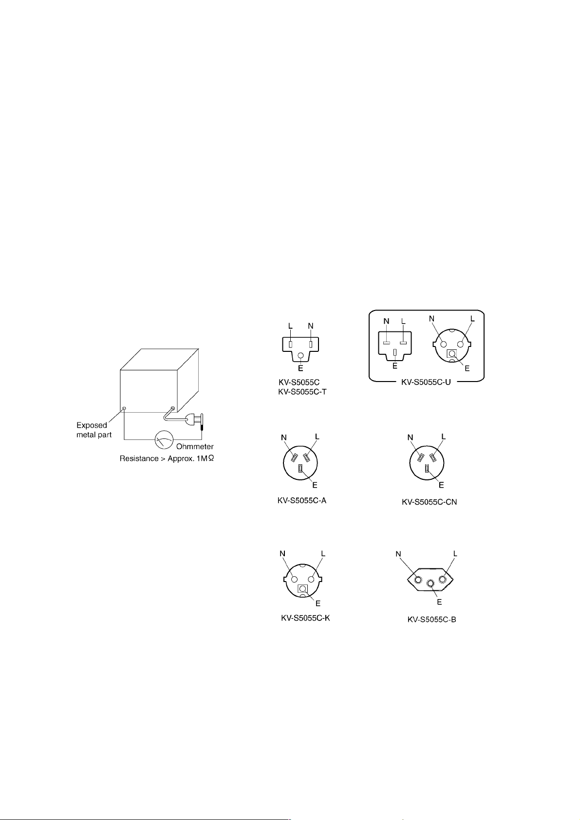
1. Unplug the power cord and check for continuity between the earth ground connection on the plug and the metal cabinet.
There should be zero ohm resistance found.
2. With the unit unplugged, short the AC Live-Neutral of the plug with a jumper wire.
3. Turn ON the power switch.
4. Measure the resistance value with an ohmmeter between the jumpered AC plug and each exposed metal cabinet part, such
as screwheads, etc.
Note
Some exposed parts may be isolated from the chassis by design. They read infinity.
5. If the measurement is less than 1 MΩ, there may be a danger of electric shock.
Note
This hazardous condition must be corrected before the unit is returned to the end user.
1.3. Standard for Repair Service
Repair service shall be provided in accordance with repair technology information such as service manual
so as to prevent fires, injury or electric shock, which can be caused by improper repair work.
1. When performing repairs, neither the products nor its parts or components shall be modified.
2. If cable assembly is supplied as the smallest unit when servicing, make sure to replace
the cable assembly.
4
1.4. For Service Technicians
ICs and LSIs are vulnerable to static electricity.
When repairing, the following precautions will help to prevent recurring malfunctions.
1. Cover plastic parts with aluminum foil.
2. Ground soldering irons.
3. Use a conductive mat on the worktable.
4. Do not hold IC or LSI pins with bare fingers.
1.5. About Lead Free Solder (PbF: Pb free)
Note
• In the information below, Pb, the symbol for lead in the periodic table of elements, will refer to standard solder or solder
that contains lead.
• We will use PbF when discussing the lead free solder used in our manufacturing process which is made from Tin (Sn),
Silver (Ag), and Copper (Cu).
• This model, and others like it, manufactured using lead free solder will have PbF stamped on the PCB. For service and
repair work we suggest using the same type of solder.
Distinction of PbF PCB
• PCBs manufactured using lead free solder will have a PbF stamp on the PCB.
Caution
• PbF solder has a melting point that is 50 ° - 70 °F, (30 ° - 40 °C) higher than Pb solder.
Use a soldering iron with temperature control and adjust it to 700 ° ± 20 °F (370 ° ± 10 °C).
• Exercise care when using higher temperature soldering irons: Do not heat the PCB for too long time in order to
prevent solder splash or damage to the PCB.
• PbF solder will tend to splash if it is heated much higher than its melting point, approximately 1100 °F (600 °C).
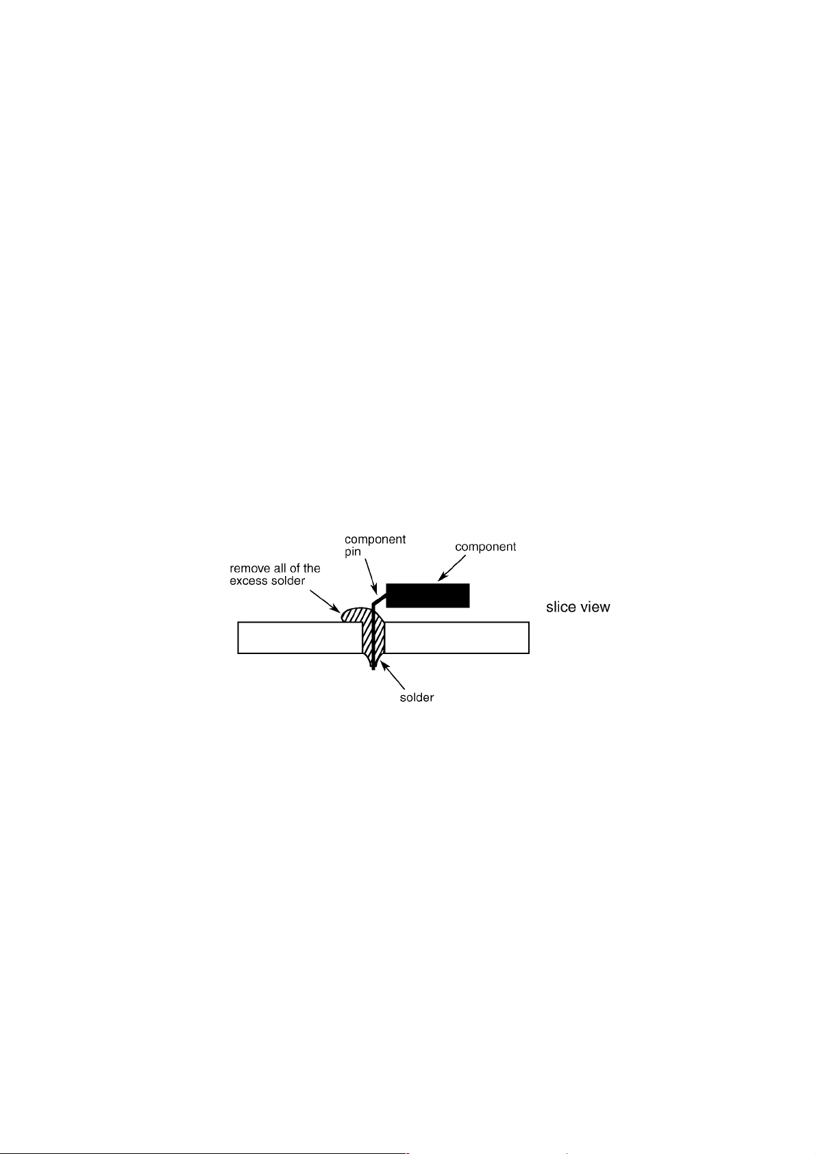
• When applying PbF solder to double layered boards, check the component side for excess solder which may flow onto
the opposite side (See figure below).
1.5.1. Suggested Pb free solder
We recommend you to use the following solder when re-soldering components for repair. Before using other Pb free solder than the
following solder, make sure to confirm that the solder maker (you use) has the license agreement for Pb free solder.
Supplier: Senju Metal Industry Co., Ltd. (http://www.senju-m.co.jp)
Part Description in Senju: EcoSolder RMA02 P3 M705 Series
1.6. About RoHS
This product is fully compliant with the national laws transposed from the EU Directive on the restriction of the use of certain
hazardous substances (RoHS) in electrical and electronic equipment, effective 1st July 2006 in the EU countries.
In order for the product to comply with the RoHS Directive, the six particular substances (lead, mercury, cadmium, hexavalent
chromium, polybrominated biphenyls, and polybrominated diphenyl ethers) have been either totally eliminated or limited to the
concentration level below maximum allowed. Consequently spare parts have been changed to RoHS-compliant parts where
applicable.
Due to the application of RoHS legislation to spare parts, non-compliant spare parts cannot be used to repair compliant products put
on the EU market on or after 1st July 2006. Therefore make sure to order and use RoHS-compliant spare parts listed in this
manual.
5

2 SPECIFICATIONS
Item Model No.
Scanner Scanning Face Duplex
Scanning Method CCD and LED for Front side
Scanning Width 305 mm (12.0 in.)
Readout Speed
Resolution Main scanning direction: 100 - 600 dpi (1 dpi step)
Image Output Binary, Grayscale, Color, MultiStream (Binary and Color, Binary and Grayscale)
Tonal Gradation Dither (64 step gradation), Error diffusion (64 step gradation), Grayscale (8 bit), Color (24 bit)
Image Control Image emphasis, Dynamic threshold, Automatic separation, Invert, White level from paper
Other Functions Patch code detection (Kodak patch 2,3,T), Double feed detection
Paper Size
*2
Thickness 0.04 to 0.2 mm (1.6 to 7.9 mils)
CCD and LED for Back side
Black & White: 50 ppm / 100 ipm (A4, 300 dpi, Portrait)
Black & White: 70 ppm / 140 ipm (A4, 200 dpi, Portrait)
Color (JPEG): 50 ppm / 100 ipm (A4, 300 dpi, Portrait)
Color (JPEG): 70 ppm / 140 ipm (A4, 200 dpi, Portrait)
Sub-scanning direction: 100 - 600 dpi (1 dpi step)
Optical resolution is 600 dpi.
48 x 70 mm (1.9 x 2.8 in.) to 297 x 432 mm (11.7 x 17 in.)
*1
KV-S5055C Series
Note: 1 mil = 1 / 1000 in.
Weight
20 to 157 g/m
Note: 1 lb. = 3.75 g/m
Detection Empty, Jam, Double-feed detection, and Bent-paper detection
Interface USB 2.0 (Connector type: B)
Hopper Capacity
Memory Size 32 MB (Standard)
200 sheets [75 g/m
2
(5.3 to 41.8 lb.)
2
(20 lb.)]
2
Note: Additional Memory
Up to 1 GB
Unit External Dimensions
(Width x Depth x Height)
Weight 18 kg (40 lb.)
Power Requirement AC 100 V to AC120 V, 50 / 60 Hz
Power
consumption
Environment Operating Temperature and
Humidity
Storage Temperature and
Humidity
Accessories Power cord, USB cable, Double-feed Roller Prevention Roller,Cleaning Paper, Blower,
PbF (Pb Free) Applied to PCB assemblies CONTROL, DRIVE, POWER, CCD(F), CCD(B),LED, USS RELAY, USR
Maximum
(Scanning)
Minimum
(Standby)
Sleep Mode 3.5 W or less (AC 100 V to 120 V)
468 x 444 x 339 mm (18.5 x 17.5 x 13.4 in.)
AC 100 V to AC240 V, 50 / 60 Hz
1.0 A (AC 100 V to 120 V)
0.5 A (AC 220 V to 240 V)
0.4 A (AC 100 V to 120 V)
0.2 A (AC 220 V to 240 V)
3.5 W or less (AC 220 V to 240 V)
Temperature: 15 °C to 30 °C (59 °F to 86 °F)
Humidity: 20 % to 80 %RH
Temperature: 0 °C to 40 °C (32 °F to 104 °F)
Humidity: 10 % to 80 %RH
Shading Sheet, CD-ROM (Installation Manual, Operation Manual, Device driver, ISIS, TWAIN
Image Capture Plus, Quick Scan Pro Demo, User Utility, Control Sheet, Warranty Information(U.S.A.
only)), Printed materials (Installation Manual, Safety Guide)
RELAY, USR SENSOR, SLIP DETECT SENSOR, STARTING SENSOR, USS/WAITING SENSOR,
PANEL, DFP HOME SENSOR, ENDING SENSOR, PAPER FEED SELECT SENSOR, BENT
RELAY, BENT PAPER SENSOR R(L), BENT PAPER SENSOR R(R), BENT PAPER SENSOR S(L),
and BENT PAPER SENSOR S(R) Boards
Note: Distinction of PbF PCB
PCBs manufactured using lead free solder will have a PbF stamp on the PCB.
Option
*3
Roller Cleaning Paper (KV-SS03)
*3
Imprinter Unit (KV-SS014)
*3
Ink Cartridge (KV-SS021)
*4
Roller Exchange Kit (KV-SS039)
Flatbed Scanner (KV-SS080)
6

Note:
*1
: KV-S5055C Series
Model Area Serial No. Power Cord
KV-S5055C USA D36 xxxx 1001 For 100 to 120 V
KV-S5055C-J USA (made in Japan) D56 xxxx 1001 For 100 to 120 V
KV-S5055C-U Europe, Russia D50 xxxx 1001 For 220 to 240 V
KV-S5055C-K Korea D53 xxxx 1001 For 220 to 240 V
KV-S5055C-T Taiwan D54 xxxx 1001 For 100 to 120 V
KV-S5055C-CN China D57 xxxx 1001 For 220 to 240 V
KV-S5055C-B Brasil D52 xxxx 1001 For 220 to 240 V
*2
: The scanning speed depends on the test environment. In addition, it differs depending on the host computer operating
environment or applications.
*3
: KV-SSxxx (All Area except for China)
KV-SSxxx-CN (Only for China)
(xxx: 03, 014, or 021)
*4
: KV-SS039 (Except for Europe, Russia, and, China)
KV-SS039-U (For Europe and Russia)
KV-SS039-CN (For China)
7
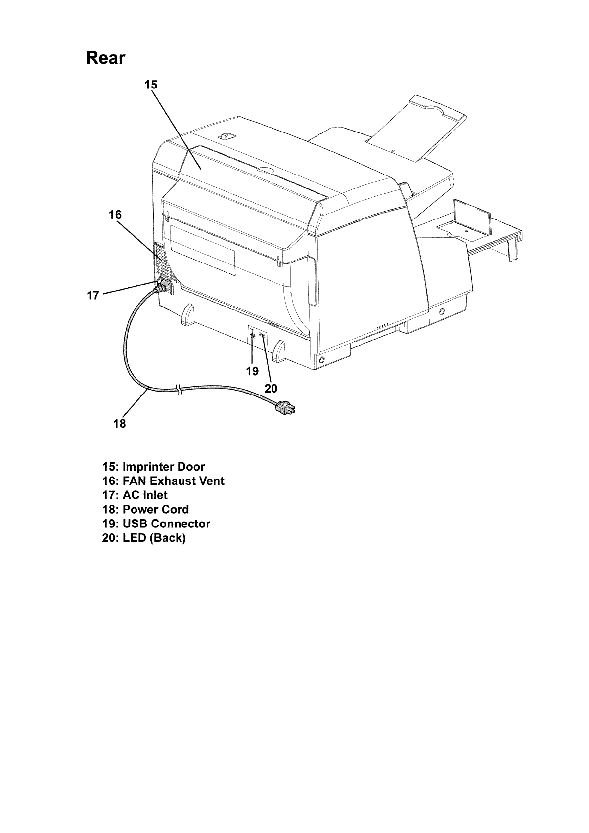
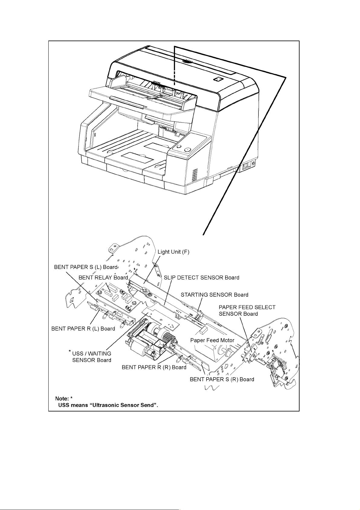
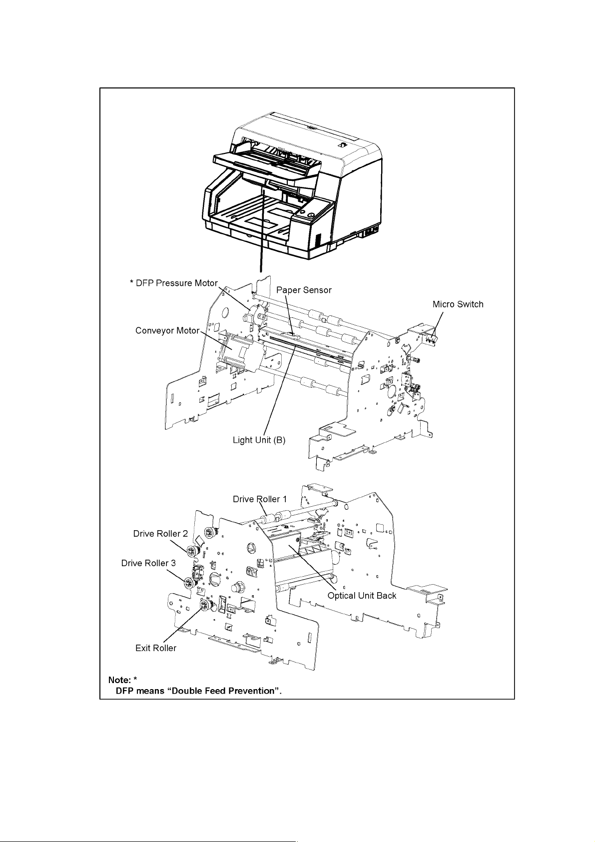
3 COMPONENT IDENTIFICATION
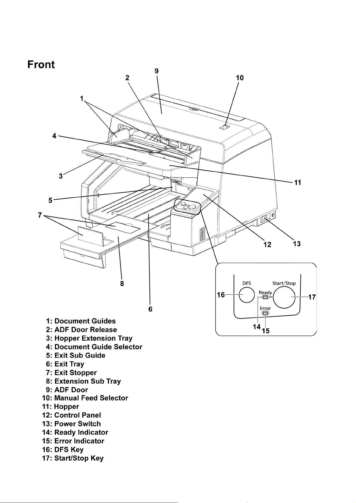
3.1. Main Part Names and Locations
8
9
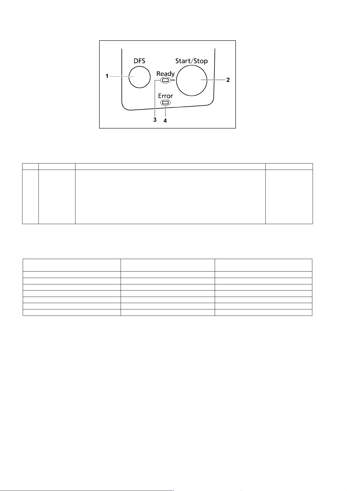
3.2. Control Panel
Fig.3.2.1 Function of Control Panel keys and indications
Name Operation Remarks
1 DFS (Double-
feed Skip) key
2 Start/Stop key (1) Push this key to start scanning if you set [Wait Key] to "Manual Feed Mode" in your
3 Ready Indicator This indicator shows the scanner status.
4 Error Indicator This indicator lights when an error occurs.
When a double-feed occurs, push this key to continue scanning the double-feed detected
sheet and the following sheet on the Hopper.
application software.
(2) During scanning, push this key to stop scanning.
(3) If you push this key when a double feed occurs, the sheet that was detected as a double
feed will be ejected from the scanner without being scanned. Scanning will stop.
Fig.3.2.2 Scanner status
Ready Indicator Error Indicator Status
(Green) (Red)
ON OFF Ready
ON Blink (Slow) Caution*
OFF ON Error
Blink (Slow) OFF Sleep
Blink (Slow) Blink (Slow) Caution* / Sleep
Blink (Fast) OFF Warming up
Blink (2 times consecutively) OFF Double Feed Skip mode
Note:*
This status indicates one of the following.: "Clean rollers", "Clean Reference Plates", or "Replace rollers"
To determine the specific condition, execute "Service Utility", and then check the status message.
10
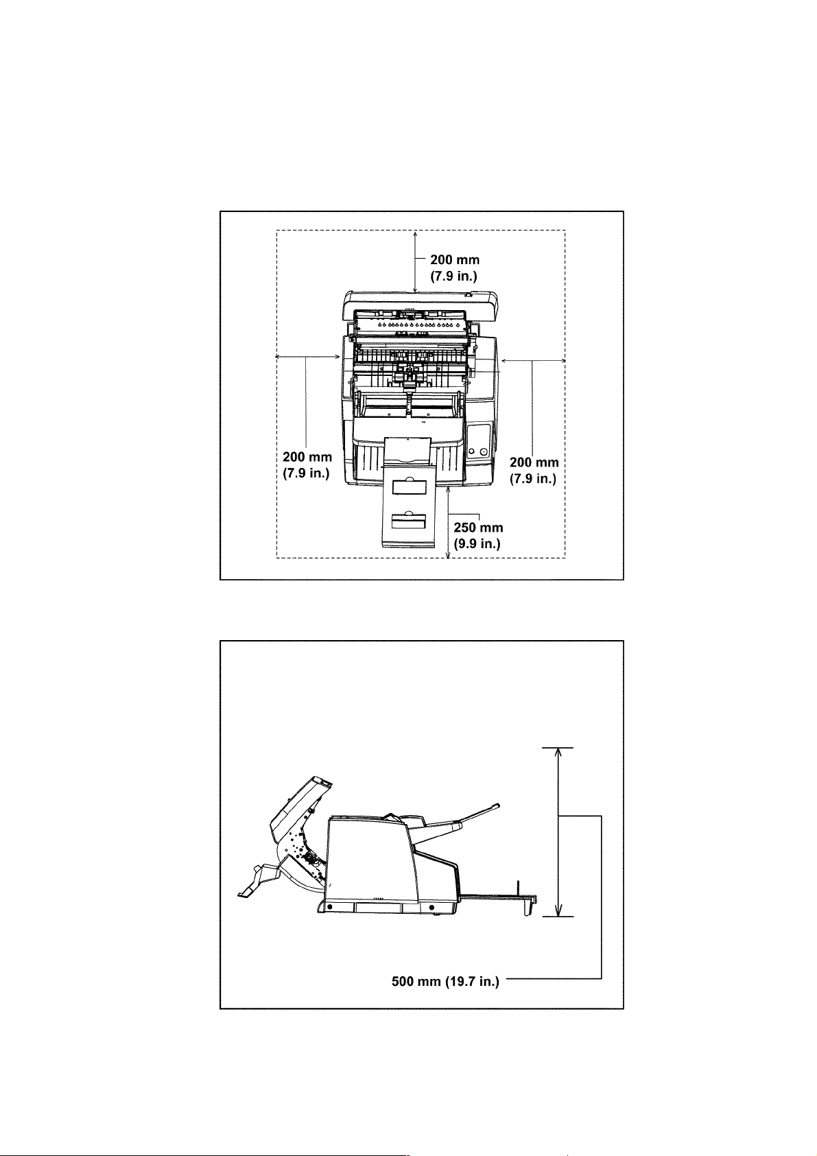
4INSTALLATION
4.1. Minimum Space Requirements
Be sure to maintain the recommended space requirements for proper ventilation.
Fig.4.1.1 Dimensions for proper ventilation
Top View
Left-side View
11
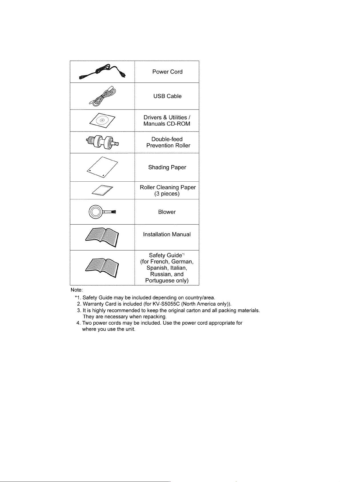
4.2. Included Accessories
Confirm that the following items are included with the scanner.
12
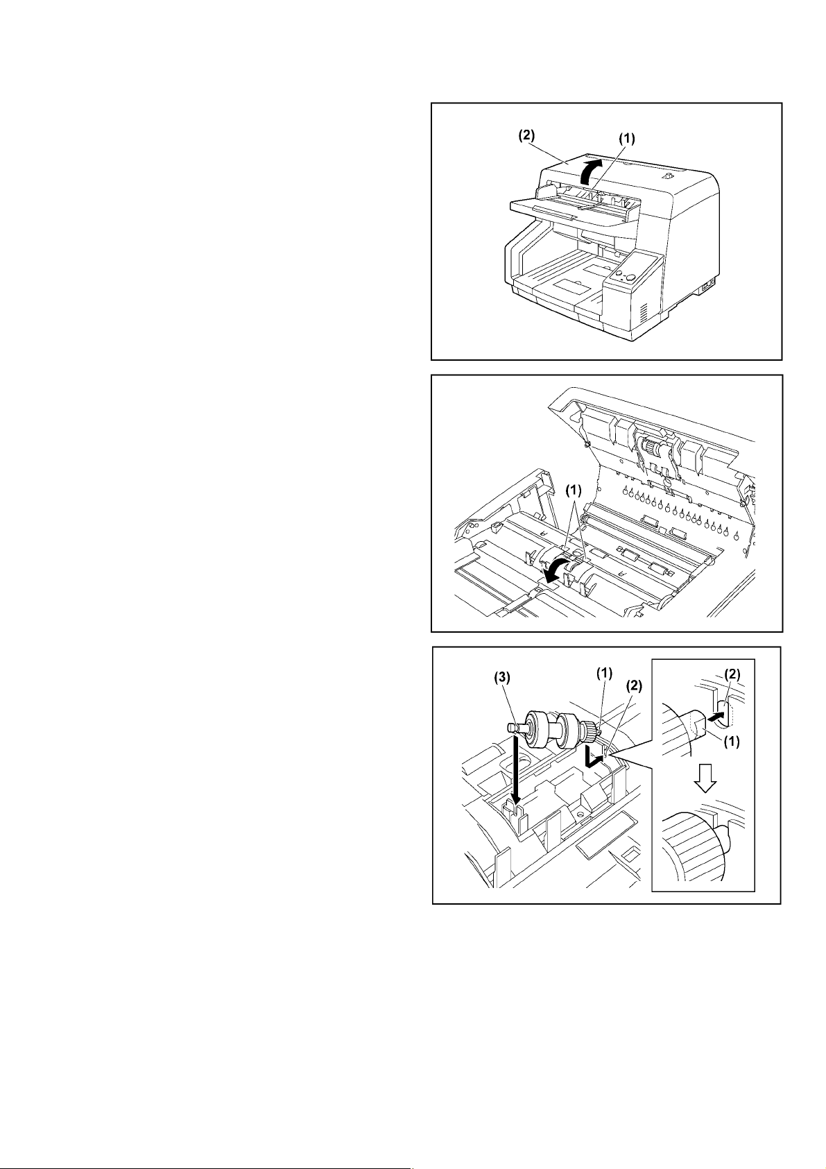
4.3. Installing Double-feed Prevention Roller
1. Remove all packing tape.
2. Push the ADF Door Release (1) to open the ADF door (2).
3. Pull towards you and remove the Double-feed Prevention
Roller Cover by using the indent (1).
4. Install the Double-feed Prevention Roller.
• Align the shaft that is shaped as indicated by (1) with the
notch in the roller mount (2), and then insert the shaft in the
notch. Push the shaft on the opposite side (3) until it clicks into
place.
Note
After you install the Double-feed Prevention Roller, make sure
that the shaft is inserted into the tab, and that the shaft will not
rotate or move. If the roller is not installed correctly, it may
cause double feeding or a paper jam.
13
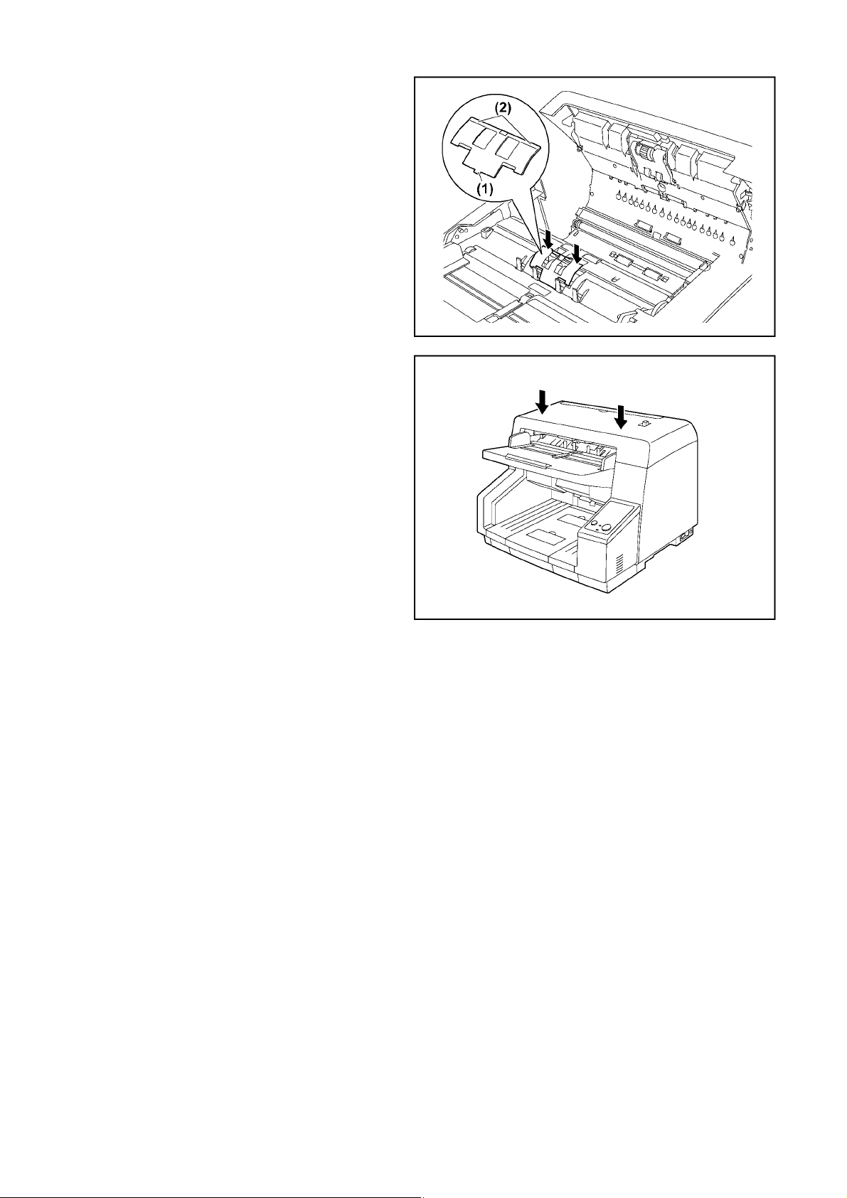
5. Insert the protrusion (1) of the Double-feed Prevention Roller
Cover into the holes on the main unit, and then push in the
part of the roller cover indicated by (2) in the direction indicated
by the arrows until it clicks into place.
Note
Make sure that the Double-feed Prevention Roller Cover does
not stick up.
If the cover is not closed properly, paper jams or damage to
the paper may occur.
6. Close the ADF Door.
• Push both sides of the ADF Door down slowly until it clicks into
place.
14
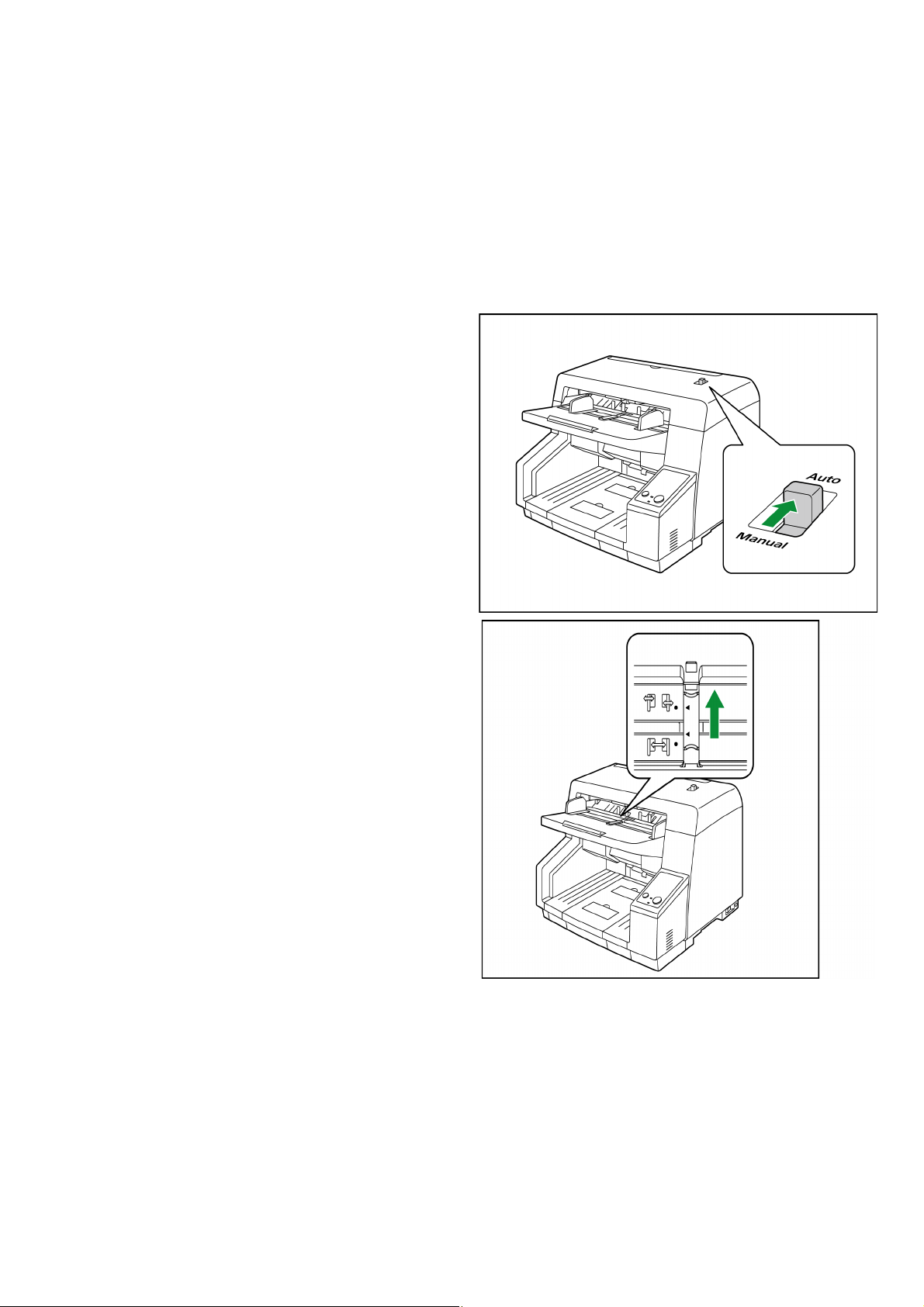
4.4. When Scanning Documents of Different Sizes Together
Note
See the following conditions for scanning documents of different sizes together.
• Document thickness
The ratio of the thickness between the thickest paper and thinnest paper must be less than 1.5.
• Document size
The ratio of the largest paper size to the smallest paper size must be less than 1.5. (The minimum size is A6)
For example, if A4 is the smallest paper set on the Hopper, the maximum size for other documents to be scanned together
is A3.
1. Set the Manual Feed Selector to "AUTO".
2. Slide the Document Guides Selector in the direction of the
arrow to unlock the Document Guides so that the guides
can be slid independently from each other.
15
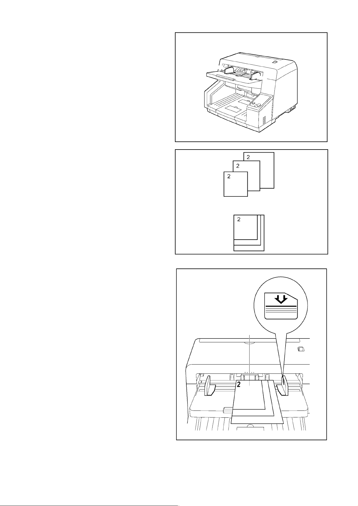
3. Spread the Document Guides as far apart as they will go.
4. Align the documents along one side of the guides.
5. Slide the Document Guides to align the document position so
that the center of the smallest sheet can be fed into the center
of the paper slot.
Note: Adjusting the left and right Document Guides to
their original position
1. Slide the Document Guides Selector to unlock the
Document Guides.
2. Spread the Document Guides as far apart as they will
go.
3. Slide the Document Guides Selector to lock the
Document Guides.
16

4.5. DIMM Module Extension
A maximum of 1024 MB (total size for front and back sides) extended memory may be required depending on the combination of
the paper size, mode, and resolution. To determine how much extended memory is required for a certain configuration, refer to
Fig. 4.5.1 and Fig. 4.5.2.
Note 1:
If configurations requiring a lot of memory (high resolution, color mode, etc.) are used with
KV-S5055C Series, the scanning will be suspended intermittently while the data is
being transferred to the computer.
As a result, the images may be disrupted slightly due to the effect of suspending the scanning.
In cases like this, the image quality will be improved by installing additional memory in the scanner.
To determine the amount of memory that is required to avoid suspending the scanning, refer to Fig.4.5.1. and Fig.4.5.2.
Note 2:
Originally, CONTROL Board has 32 MB memory built in.
Note 3:
For the additional memory, the scanner requires the same type of memories for each side (Front and Back)
to be installed at the same time. (For example: “128” means that you must install 128 MB of memory for front-side
scanning and 128 MB of memory for back-side scanning.)
Note 4: Recommended memory
(1) 144 pin SDRAM (Unbuffered SO-DIMM)
(2) Non ECC
(3) + 3.3 V ± 0.3 V power supply
(4) Frequency / CAS Latency: 100 MHz / CL=2 or 133 MHz / CL=2
(5) Support for Full Page Burst
(6) Memory size: 128 MB, 256 MB, or 512 MB
(7) Height: Less than 31.75 mm (1.25 in.)
Note 5: “X”
“X” in the Fig. 4.5.1 and Fig. 4.5.2 means the scanning will be suspended intermittently (START/STOP function
will operate.) even if the maximum amount of memory (total 1024 MB) is installed.
17

Fig.4.5.1: Additional memory size -1
(Unit: MB)
*1
: 305 mm x 2,540 mm (12.0 x 100 in.)
Mode Size dpi
100 200 300 400 500 600
Binary
*1
SC's Max
0 0 128 128 128 128
Double Letter 00000128
Legal 000000
Letter 000000
A3 00000128
A4 000000
A5 000000
A6 000000
B4 000000
B5 000000
B6 000000
8 bit Gray
*1
SC's Max
128 128 128 256 512 512
Double Letter 0 128 128 128 128 128
Legal 0 0 128 128 128 128
Letter 0 0 128 128 128 128
A3 0 128 128 128 128 128
A4 0 0 128 128 128 128
A5 0 0 0 128 128 128
A6 00000128
B4 0 0 128 128 128 128
B5 0 0 0 128 128 128
B6 0000128128
24 bit Color
*1
SC's Max
256512XXXX
Double Letter 128 128 256 256 512 X
Legal 128 128 128 256 256 256
Letter 128 128 128 256 256 256
A3 128 128 256 256 512 X
A4 128 128 128 256 256 256
A5 0 128 128 128 256 256
A6 0 128 128 128 128 128
B4 128 128 128 256 256 512
B5 0 128 128 128 256 256
B6 0 128 128 128 128 256
18
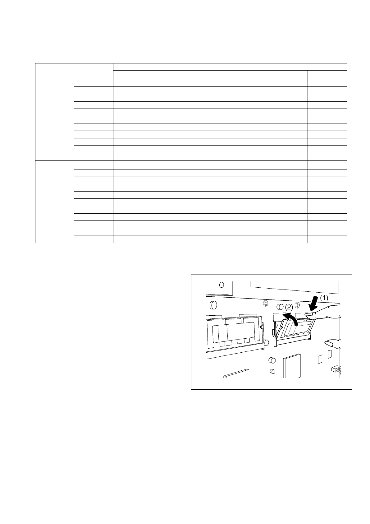
Fig.4.5.2: Additional memory size -2
(Unit: MB)
*1:
305 mm x 2,540 mm (12.0 x 100 in.)
Mode Size dpi
100 200 300 400 500 600
Binary + 8 bit
Gray
*1
SC's Max
Double Letter 0 128 128 128 128 128
128128XXXX
Legal 0 128 128 128 128 128
Letter 0 0 128 128 128 128
A3 0 128 128 128 128 128
A4 0 0 128 128 128 128
A5 0 0 0 128 128 128
A6 0 0 0 0 128 128
B4 0 0 128 128 128 128
B5 0 0 128 128 128 128
B6 0 0 0 128 128 128
Binary +
24 bit Color
*1
SC's Max
256512XXXX
Double Letter 128 128 256 256 512 X
Legal 128 128 128 256 256 256
Letter 128 128 128 256 256 256
A3 128 128 256 256 512 X
A4 128 128 128 256 256 256
A5 0 128 128 128 256 256
A6 0 128 128 128 128 128
B4 128 128 128 256 256 512
B5 0 128 128 128 256 256
B6 0 128 128 128 128 256
4.6. Installing DIMM Modules
1. Remove the Cover Plate. (See 8.2.1.)
2. Insert the DIMM Module into the memory slot (CN0017) on the
CONTROL Board in the direction of the arrow (1), and then
push the module down in the direction of the arrow (2) until
the notches of the module on both sides lock into place.
3. Insert another DIMM Module similarly into the other memory
slot (CN0018) on the CONTROL Board.
19
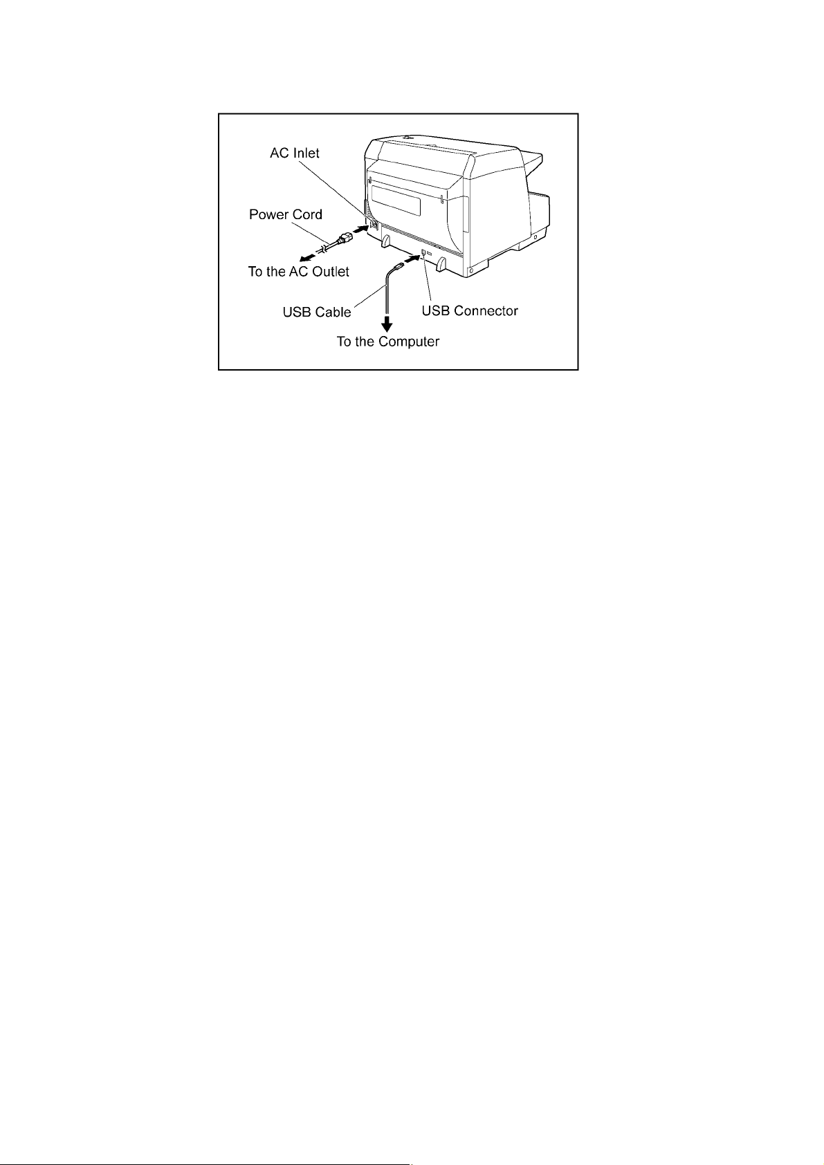
4.7. Connecting the Scanner to a Personal Computer
Connect the accessories’ Power Cord and USB cable to the back of the unit.
Caution:
1. Only use the Power Cord and USB Cable enclosed in this scanner.
2. Be sure to connect the scanner directly to the USB interface port on the PC.
We cannot guarantee that the scanner will work properly if it is connected to a USB hub.
20

4.8. System Requirements
When using the scanner, the minimum system requirements are as follows.
Computer IBM PC/AT or compatible machine with a CD-ROM drive
CPU
Operating System
Interface USB 2.0
Memory 1 GB
Hard Disk Drive 5 GB free space is required.
Note
1. The above system requirements may not meet the requirements of all operating systems and bundled
application software.
2. The scanning speed differs depending on the host computer’s operating environment or application.
3. If you connect the scanner to a USB hub, it is not guaranteed to work.
Abbreviations
• Windows
• Windows® XP refers to the Microsoft® Windows® XP operating system (hereafter Windows XP).
• Windows Vista® refers to the Microsoft® Windows Vista® operating system (hereafter Windows Vista).
• Windows® 7 refers to the Microsoft® Windows® 7 operating system (hereafter Windows 7).
Trademarks
1. Intel and Intel Core are trademarks of Intel Corporation in the U.S. and other countries.
2. Microsoft, Windows, and Windows Vista are either registered trademarks or trademarks of Microsoft
Corporation in the United States and/or other countries.
3. All other trademarks identified herein are the property of their respective owners.
®
refers to the Microsoft® Windows® operating system (hereafter Windows).
Intel® Core™ 2 Duo, 1.8 GHz or higher
®
Windows
XP (64 bit Edition is not supported.), Windows Vista®, or Windows®7
4.9. Installing the Driver and Software
Following the instructions in the scanner’s Installation Manual, install the scanner driver and software that is included on
the enclosed CD-ROM.
21
5 SECTIONAL VIEW
5.1. Bottom Block
22
5.2. Back Block
23
5.3. Upper Block
24
5.4. Lower Block
5.4.1. Mechanical Parts
25

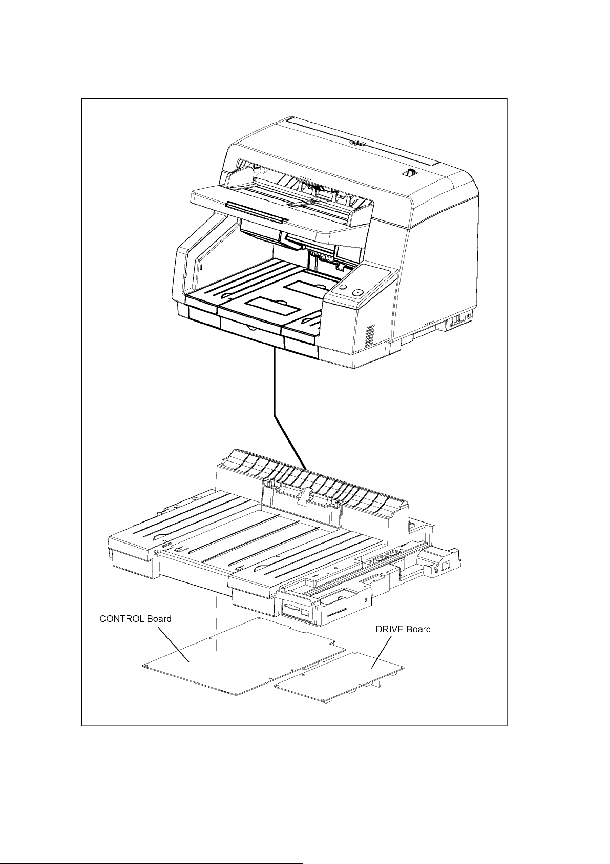
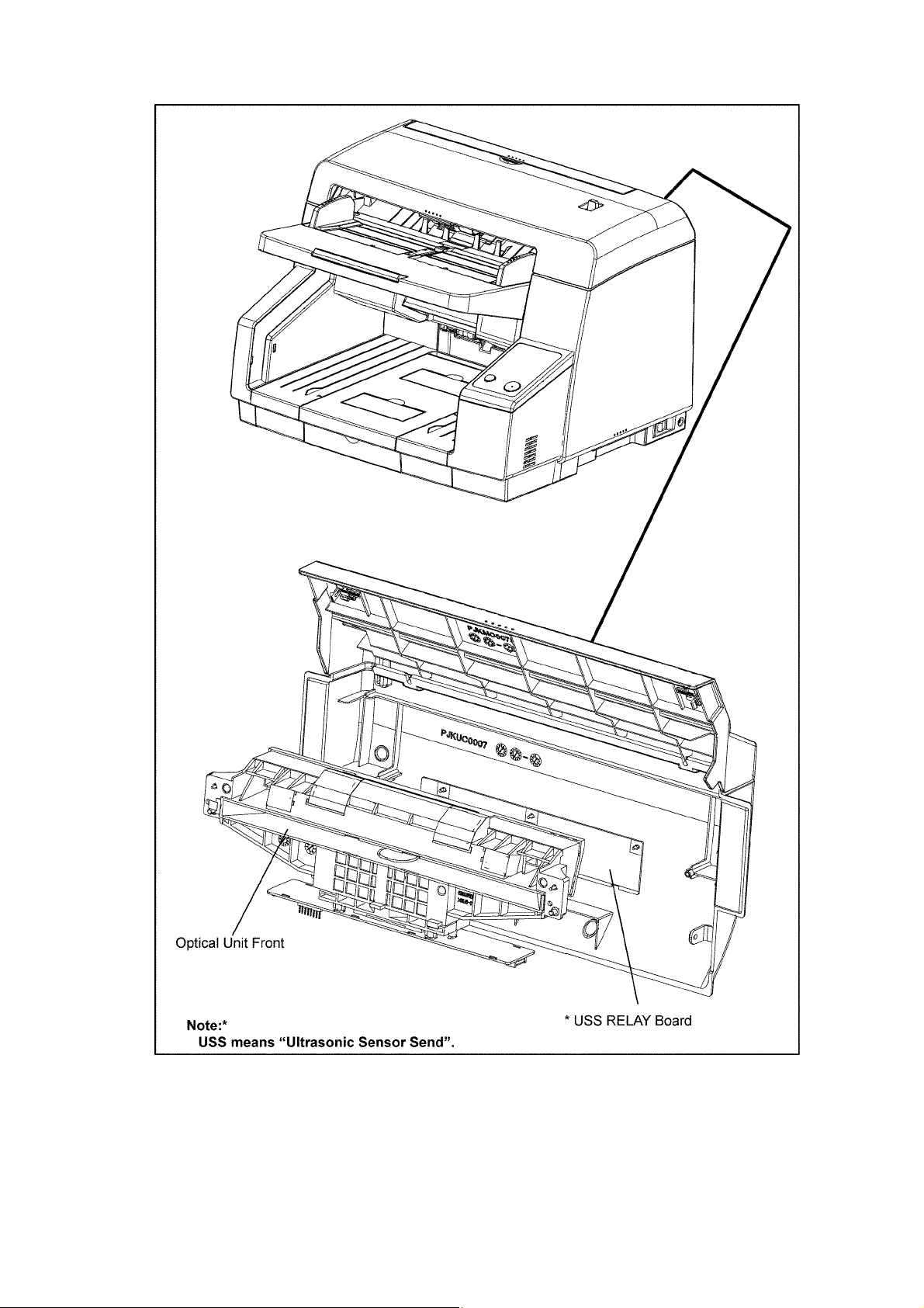
5.4.2. Boards
26
6 MECHANICAL FUNCTION
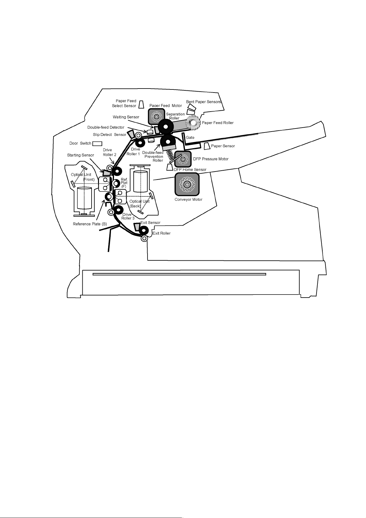
6.1. Paper Feed Mechanism (Auto)
(Fig. 6.1.1)
1. When the documents are set on the Hopper and the scanning command is issued from PC, the Conveyor Motor will be driven
to rotate the three Drive Rollers (Drive Roller 1 to 3) and Exit Roller. And at this time, the gate will open.
2. Then, the Paper Feed Motor will be driven to rotate the Paper Feed Roller and the Separation Roller in the feed direction.
At this time, the Paper Feed Roller will move down until the roller is in contact with the documents, which enables the roller to
feed the documents.
The Double-feed Prevention Roller is supported by shaft fixed via a torque limiter, and it is pushed against the Separation Roller.
3. When documents enter the separation section, the Double-feed Prevention Roller exerts a manipulation force onto them,
which depends on a set torque. In the case of continuous paper feed, the documents are separated by this manipulation force,
so only one sheet of the documents is fed to the scanning section.
When the document passes through the Waiting Sensor, the Paper Feed Motor will be driven to rotate the Double-feed
Prevention Roller in the reverse direction to ensure separation of the first document from the following documents. At this time,
the Paper Feed Roller rises to separate from the documents.
27
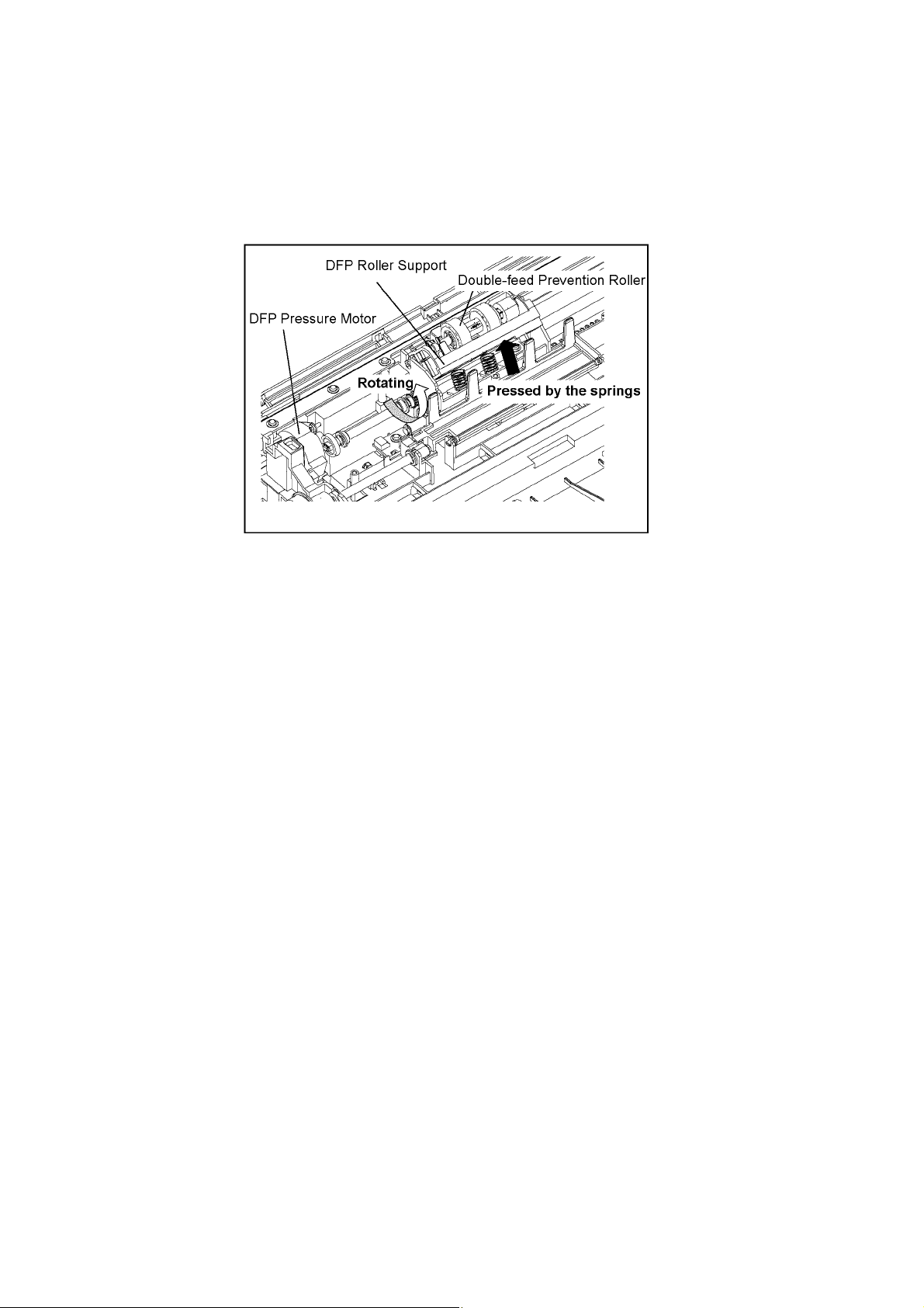
4. Then, the leading edge of the document advances to the Drive Roller 1 position, and then passes through the Slip Detect Sensor.
At this time, if the document does not advance within a defined period, the pressure applied to the Separation Roller from the
Double-feed Prevention Roller is strengthened to prevent the document from slipping.
(For the pressure mechanism, see Fig. 6.1.2.)
When the leading edge of the document reaches the Slip Detect Sensor, the Paper Feed Motor will stop.
(Fig. 6.1.2) Pressure Mechanism
5. When the leading edge of the document passes through the Starting Sensor, image scanning starts after a defined period.
(i.e., the time required for the document to advance from the Starting Sensor to the scanning start point)
6. The document passes through the Exit Sensor and exits from the scanner.
7. When the trailing edge of the document passes through the Waiting Sensor, the Paper Feed Motor is driven again to feed
the 2nd document.
8. 2 to 7 above are repeated.
Note:
When the scanner’s buffer becomes full, the scanner stops to prevent buffer overflow, while continuing
to allow data to be transferred to the PC.
28
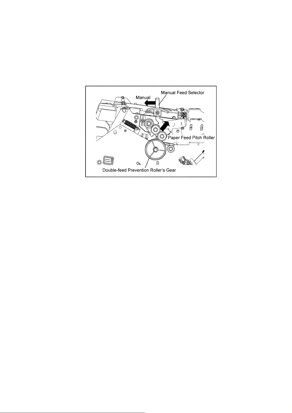
6.2. Paper Feed Mechanism (Manual)
When scanning multipart paper with the Manual Feed Selector set to “AUTO”, the Double-feed Prevention Roller is
pressed against the Separation Roller, and this results in a separating force being applied to the document, which will separate
the layers, resulting in damage to the document.
This problem can be avoided by scanning multipart paper with the Manual Feed Selector set to "Manual".
With “MANUAL” set, the Double-feed Prevention Roller's gear is released from the Paper Feed Pitch Roller, and so multipart paper
can be fed and scanned as if it were a single sheet of paper.
(In this case, the Double-feed Prevention Roller operates as a free roller.)
Note:
Do not scan multipart paper with the Manual Feed Selector set to “AUTO”.
When scanning multipart paper, be sure the Manual Feed Selector is set to “MANUAL”.
29
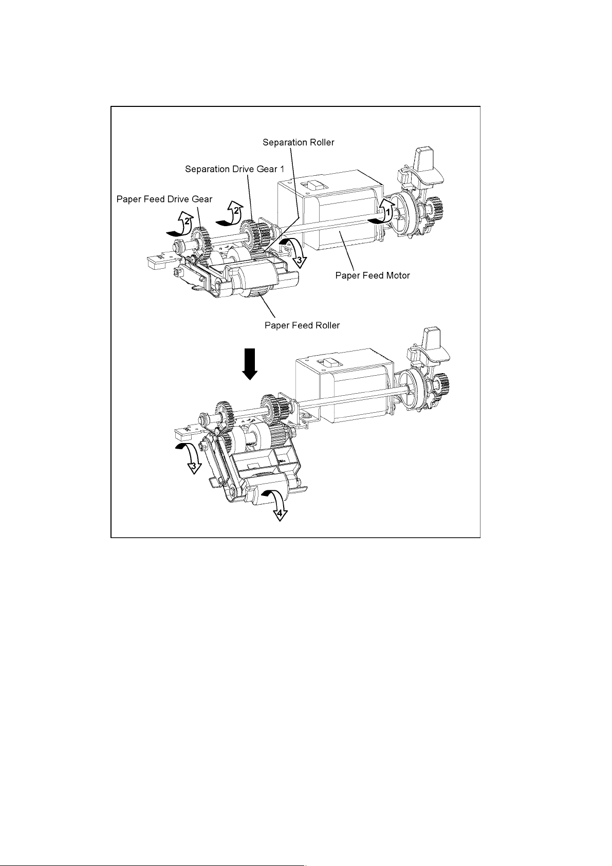
6.3. Paper Feed Operation
1. When the Paper Feed Motor rotates the Paper Feed Motor in the paper feed direction, Paper Feed Roller will go down
until the roller is in contact with, and then rotate in the paper feed direction. (Arrows 1 →2 → 3 → 4)
At this time, Separation Roller will also rotate in the paper feed direction. (Arrows 1 →2 → 3)
30
 Loading...