

Philips KTY84-151, KTY84-150, KTY84-130 Datasheet
DISCRETE SEMICONDUCTORS
DATA SH EET
M3D051
KTY84-1 series
Silicon temperature sensors
Product specification
Supersedes data of 1996 Dec 06
File under Discrete Semiconductors, SC17
1998 Apr 09
Philips Semiconductors Product specification
Silicon temperature sensors KTY84-1 series
DESCRIPTION
The temperature sensors in the KTY84-1 series have a
positive temperature coefficient of resistance and are
suitable for use in measurement and control systems over
a temperature range of −40 to +300 °C. The sensors are
handbook, halfpage
ka
MLA427
encapsulated in the SOD68 (DO-34) leaded package.
Tolerances of 0.5% or other special selections are
available on request.
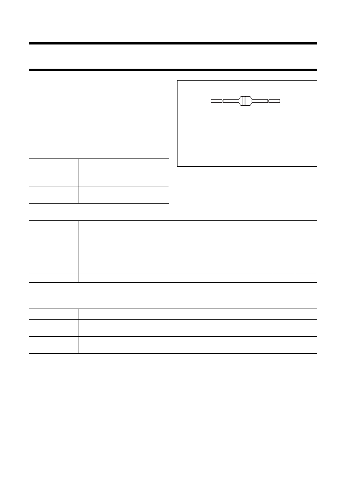
The first (green) band indicates the negative connection.
The second (coloured) band provides type identity.
The sensor must be operated with the lower potential at the
marked connection.
MARKING
Fig.1 Simplified outline (SOD68; DO-34).
TYPE NUMBER MARKING BAND COLOUR
KTY84-130 yellow
KTY84-150 grey
KTY84-151 black
KTY84-152 blue
QUICK REFERENCE DATA
SYMBOL PARAMETER CONDITIONS MIN. MAX. UNIT
R
100
sensor resistance T
= 100 °C; I
amb
cont
=2mA
KTY84-130 970 1030 Ω
KTY84-150 950 1050 Ω
KTY84-151 950 1000 Ω
KTY84-152 1000 1050 Ω
T
amb
ambient operating temperature −40 +300 °C
LIMITING VALUES
In accordance with the Absolute Maximum Rating System (IEC 134).
SYMBOL PARAMETER CONDITIONS MIN. MAX. UNIT
I
cont
T
amb
T
stg
continuous sensor current in free air; T
in free air; T
ambient operating temperature −40 +300 °C
storage temperature −55 +300 °C
=25°C; note 1 − 10 mA
amb
= 300 °C − 2mA
amb
Note
1. For temperatures greater than 200 °C, a sensor current of I
= 2 mA must be used.
cont
1998 Apr 09 2

Philips Semiconductors Product specification
Silicon temperature sensors KTY84-1 series
CHARACTERISTICS
T
= 100 °C, in liquid, unless otherwise specified.
amb
SYMBOL PARAMETER CONDITIONS MIN. TYP. MAX. UNIT
R
100
sensor resistance I
KTY84-130 970 − 1030 Ω
KTY84-150 950 − 1050 Ω
KTY84-151 950 − 1000 Ω
KTY84-152 1000 − 1050 Ω
TC temperature coefficient − 0.61 − %/K
R
250/R100
R
25/R100
resistance ratio T
resistance ratio T
τ thermal time constant; note 1 in still air − 20 − s
rated temperature range −40 − +300 °C
=2mA
cont
= 250 °C and 100 °C 2.111 2.166 2.221
amb
=25°C and 100 °C 0.595 0.603 0.611
amb
in still liquid; note 2 − 1 − s
in flowing liquid; note 2 − 0.5 − s
Notes
1. The thermal time constant is the time taken for the sensor to reach 63.2% of the total temperature difference.
For example, if a sensor with a temperature of 25 °C is moved to an environment with an ambient temperature of
100 °C, the time for the sensor to reach a temperature of 72.4 °C is the thermal time constant.
2. Inert liquid, e.g. FC43 manufactured by the 3M company.
200
T
amb
MCD398
(°C)
30
handbook, halfpage
∆ T
(K)
20
10
0
−10
−20
−30
−100
MCD399
KTY84 - 150
KTY84 - 130
- 151
- 152
KTY84 - 150
0 100 300
200
T
amb
(°C)
R
(kΩ)
3
2
1
0
−100
handbook, halfpage
0 100 300
Fig.2 Maximum expected temperature
error (∆T).
1998 Apr 09 3
I
= 2mA.
cont
Fig.3 Sensor resistance as a function of ambient
temperature; average values.
Philips Semiconductors Product specification
Silicon temperature sensors KTY84-1 series
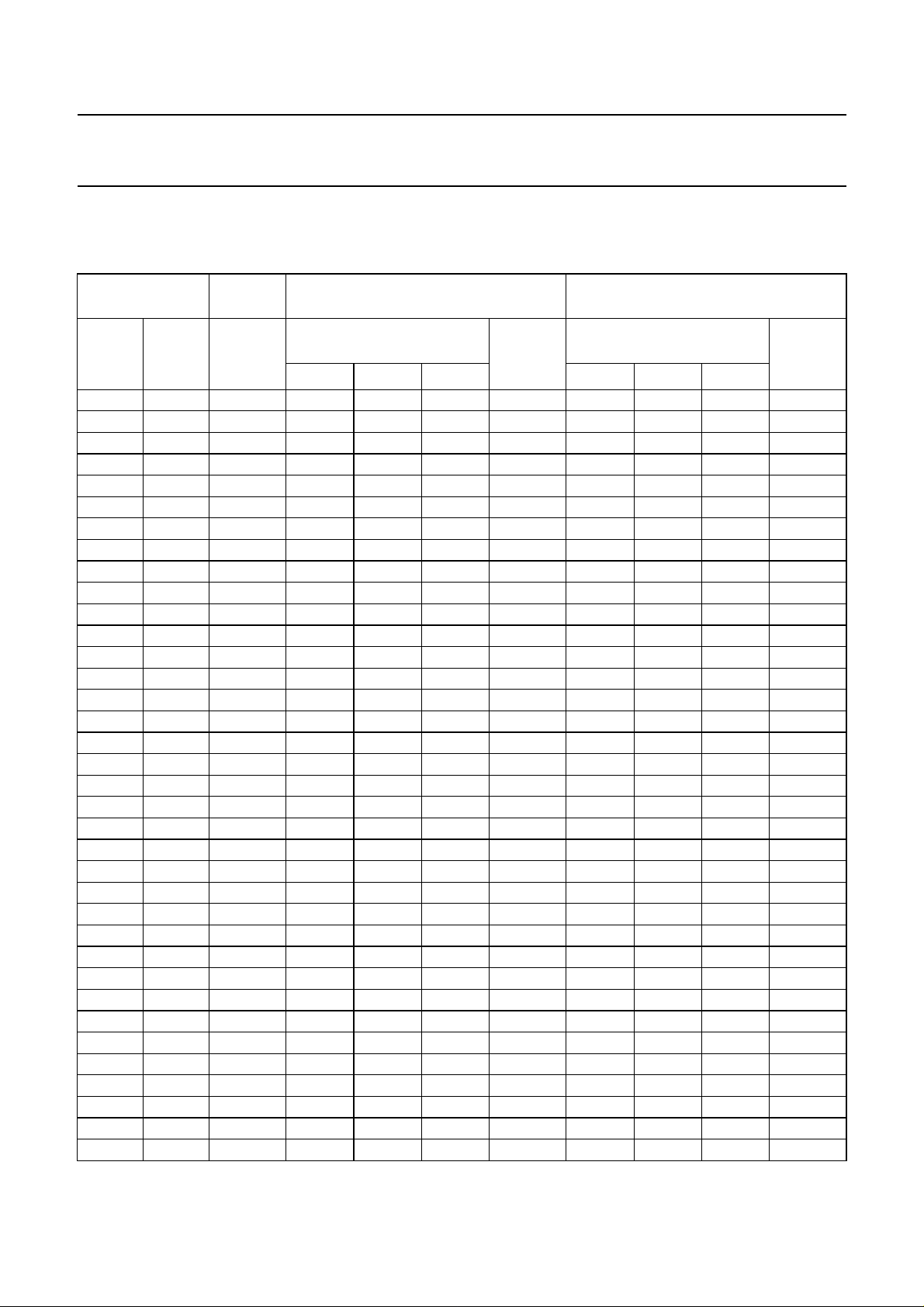
Table 1 Ambient temperature, corresponding resistance, temperature coefficient and maximum expected temperature
error for KTY84-130 and KTY84-150
= 2 mA.
I
cont
AMBIENT
TEMPERATURE
(°C) (°F) (%/K)
−40 −40 0.84 340 359 379 ±6.48 332 359 386 ±8.85
−30 −22 0.83 370 391 411 ±6.36 362 391 419 ±8.76
−20 −4 0.82 403 424 446 ±6.26 394 424 455 ±8.7
−10 14 0.80 437 460 483 ±6.16 428 460 492 ±8.65
0 32 0.79 474 498 522 ±6.07 464 498 532 ±8.61
10 50 0.77 514 538 563 ±5.98 503 538 574 ±8.58
20 68 0.75 555 581 607 ±5.89 544 581 618 ±8.55
25 77 0.74 577 603 629 ±5.84 565 603 641 ±8.54
30 86 0.73 599 626 652 ±5.79 587 626 665 ±8.53
40 104 0.71 645 672 700 ±5.69 632 672 713 ±8.5
50 122 0.70 694 722 750 ±5.59 679 722 764 ±8.46
60 140 0.68 744 773 801 ±5.47 729 773 817 ±8.42
70 158 0.66 797 826 855 ±5.34 781 826 872 ±8.37
80 176 0.64 852 882 912 ±5.21 835 882 929 ±8.31
90 194 0.63 910 940 970 ±5.06 891 940 989 ±8.25
100 212 0.61 970 1000 1030 ±4.9 950 1000 1050 ±8.17
110 230 0.60 1029 1062 1096 ±5.31 1007 1062 1117 ±8.66
120 248 0.58 1089 1127 1164 ±5.73 1067 1127 1187 ±9.17
130 266 0.57 1152 1194 1235 ±6.17 1128 1194 1259 ±9.69
140 284 0.55 1216 1262 1309 ±6.63 1191 1262 1334 ±10.24
150 302 0.54 1282 1334 1385 ±7.1 1256 1334 1412 ±10.8
160 320 0.53 1350 1407 1463 ±7.59 1322 1407 1492 ±11.37
170 338 0.52 1420 1482 1544 ±8.1 1391 1482 1574 ±11.96
180 356 0.51 1492 1560 1628 ±8.62 1461 1560 1659 ±12.58
190 374 0.49 1566 1640 1714 ±9.15 1533 1640 1747 ±13.2
200 392 0.48 1641 1722 1803 ±9.71 1607 1722 1837 ±13.85
210 410 0.47 1719 1807 1894 ±10.28 1683 1807 1931 ±14.51
220 428 0.46 1798 1893 1988 ±10.87 1760 1893 2026 ±15.19
230 446 0.45 1879 1982 2085 ±11.47 1839 1982 2125 ±15.88
240 464 0.44 1962 2073 2184 ±12.09 1920 2073 2226 ±16.59
250 482 0.44 2046 2166 2286 ±12.73 2003 2166 2329 ±17.32
260 500 0.42 2132 2261 2390 ±13.44 2087 2261 2436 ±18.15
270 518 0.41 2219 2357 2496 ±14.44 2172 2357 2543 ±19.36
280 536 0.38 2304 2452 2600 ±15.94 2255 2452 2650 ±21.21
290 554 0.34 2384 2542 2700 ±18.26 2333 2542 2751 ±24.14
300 572 0.29 2456 2624 2791 ±22.12 2404 2624 2844 ±29.05
TEMP.
COEFF.
KTY84-130 KTY84-150
RESISTANCE
(Ω)
MIN. TYP. MAX. MIN. TYP. MAX.
TEMP.
ERROR
(K)
RESISTANCE
(Ω)
TEMP.
ERROR
(K)
1998 Apr 09 4
 Loading...