

Philips KMI15-1 Datasheet

DISCRETE SEMICONDUCTORS
DATA SH EET
KMI15/1
Integrated rotational speed sensor
Preliminary specification
File under Discrete Semiconductors, SC17
1996 Dec 05

Philips Semiconductors Preliminary specification
Integrated rotational speed sensor KMI15/1
FEATURES
• Digital current output signal
• Zero speed capability
• Wide air gap
• Wide temperature range
• Insensitive to vibration
• EMC resistant.
DESCRIPTION
The KMI15/1 sensor detects rotational speed of ferrous
gear wheels and reference marks
(1)
.
The sensor consists of a magnetoresistive sensor
element, a signal conditioning integrated circuit in bipolar
technology and a magnetized ferrite magnet.
The frequency of the digital current output signal is
proportional to the rotational speed of a gear wheel.
CAUTION
Do not press two or more products together against their
magnetic forces.
PINNING
PIN DESCRIPTION
1V
CC
2V−
handbook, halfpage
12
MBH781
(1) The sensor contains a customized integrated circuit. Usage in
hydraulic brake systems and in systems with active brake
control is forbidden.
Fig.1 Simplified outline; (SOT453B).
QUICK REFERENCE DATA
SYMBOL PARAMETER MIN. TYP. MAX. UNIT
V
CC
I
CC (low)
I
CC (high)
DC supply voltage − 12 − V
current output signal low − 7 − mA
current output signal high − 14 − mA
d sensing distance 0 to 2.5 0 to 2.9 − mm
f
t
T
amb
operating tooth frequency 0 − 25000 Hz
ambient operating temperature −40 − +85 °C
1996 Dec 05 2

Philips Semiconductors Preliminary specification
Integrated rotational speed sensor KMI15/1
LIMITING VALUES
In accordance with Absolute Maximum Rating System (IEC 134).
SYMBOL PARAMETER CONDITIONS MIN. MAX. UNIT
V
CC
T
stg
T
amb
T
sld
Note
1. With R
(see Fig.7).
CHARACTERISTICS
=25°C; VCC= 12 V; d = 2.1 mm; ft= 2 kHz; test circuit: see Fig.7; RL=115Ω; sensor positioning: see Fig.15;
T
amb
gear wheel: module 2 mm; material 1.0715; unless otherwise specified.
DC supply voltage T
= −40 to +85 °C; RL=115Ω− 16 V
amb
storage temperature −40 +150 °C
ambient operating temperature −40 +85 °C
soldering temperature t ≤ 10 s − 260 °C
output short-circuit duration to GND continuous; note 1
= 115 Ω the device is continuously protected against wrong polarity of DC supply voltage (VCC) to GND
L
SYMBOL PARAMETER CONDITIONS MIN. TYP. MAX. UNIT
I
CC (low)
I
CC (high)
t
r
t
f
t
d
current output signal low see Figs 6 and 8 5.6 7.0 8.4 mA
current output signal high see Figs 6 and 8 11.2 14.0 16.8 mA
output signal rise time CL= 100 pF; see Fig.9; 10 to 90% value − 0.5 −µs
output signal fall time CL= 100 pF; see Fig.9; 10 to 90% value − 0.7 −µs
switching delay time between stimulation pulse (generated
− 1 −µs
by a coil) and output signal
f
t
operating tooth frequency for both rotation directions 0 − 25000 Hz
d sensing distance see Fig.15 and note 1 0 to 2.5 0 to 2.9 − mm
δ duty cycle see Fig.6 30 50 70 %
Note
1. High rotational speeds of wheels reduce the sensing distance due to eddy current effects (see Fig.17).
1996 Dec 05 3
Philips Semiconductors Preliminary specification
Integrated rotational speed sensor KMI15/1
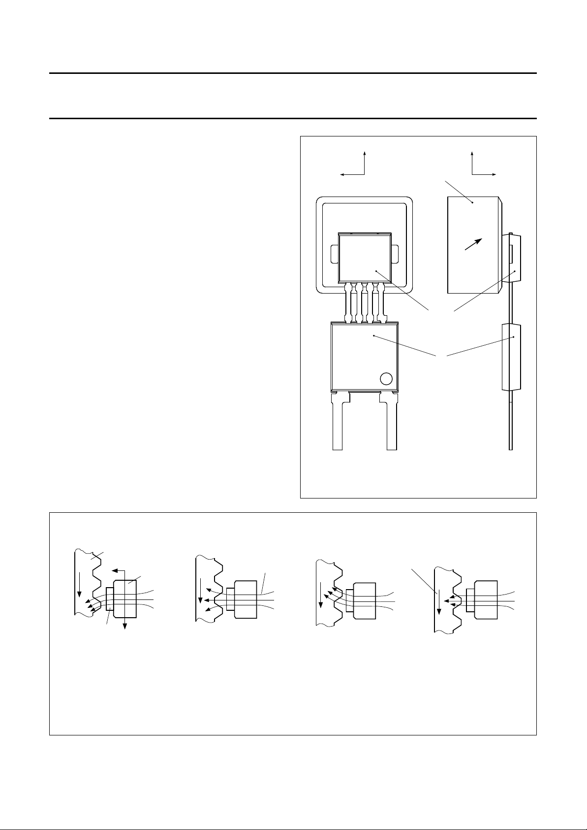
FUNCTIONAL DESCRIPTION
The KMI15/1 sensor is sensitive to the motion of ferrous
gear wheels or reference marks. The functional principle is
shown in Fig.3. Due to the effect of flux bending, the
different directions of magnetic field lines in the
magnetoresistive sensor element will cause an electrical
signal. Because of the chosen sensor orientation and the
direction of ferrite magnetization, the KMI15/1 is sensitive
to movement in the ‘y’ direction in front of the sensor only
(see Fig.2).
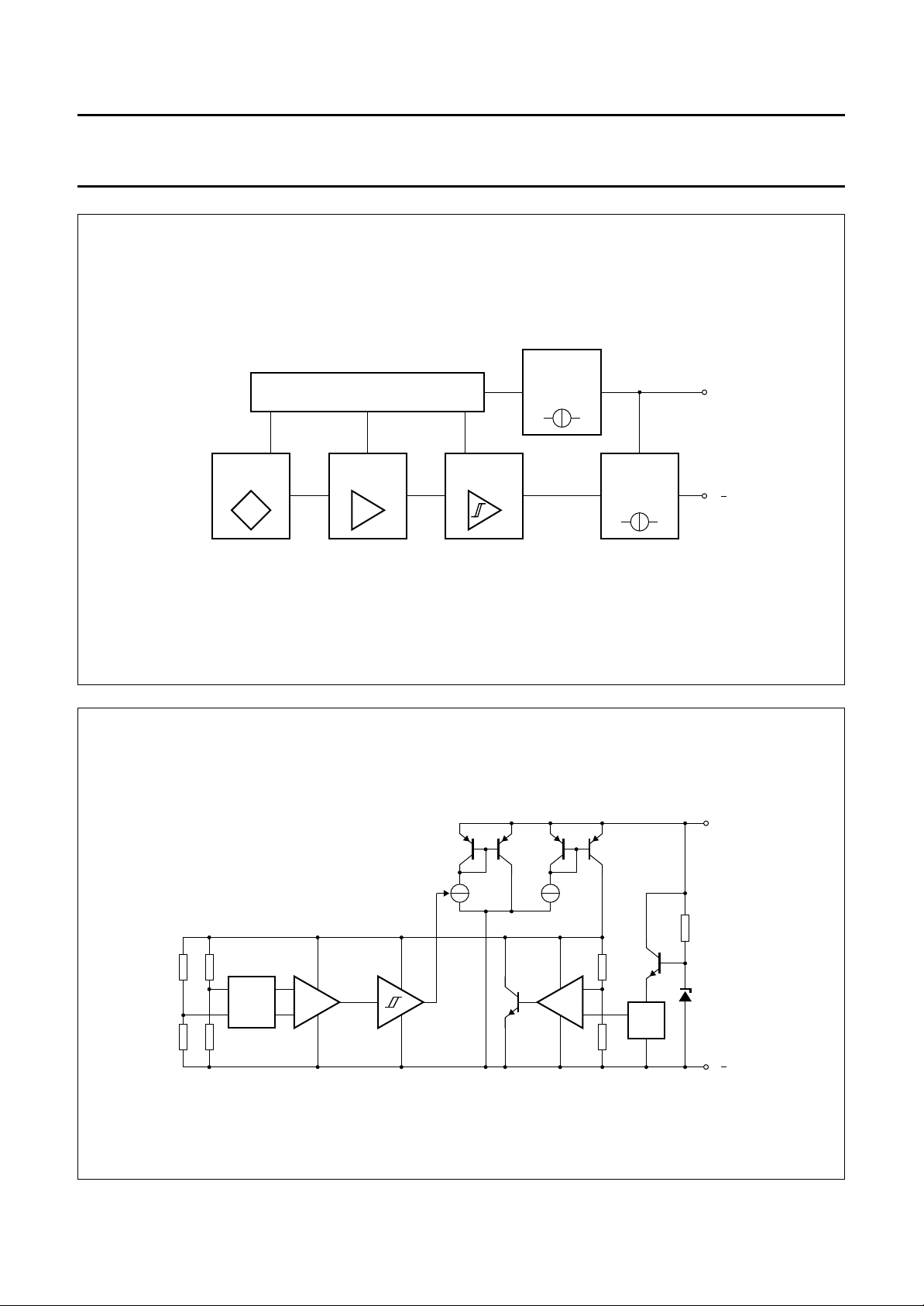
The magnetoresistive sensor element signal is amplified,
temperature compensated and passed to a Schmitt trigger
in the conditioning integrated circuit (Figs 4 and 5).
The digital output signal level (see Fig.6) is independent of
the sensing distance within the measuring range (Fig.14).
A (2-wire) output current enables safe transfer of the
sensor signal to the detecting circuit (see Fig.7).
The integrated circuit housing is separated from the
sensor element housing to optimize the sensor behaviour
at high temperatures.
handbook, halfpage
y
xx
magnet with
direction of
magnetization
sensor
IC
z
handbook, full pagewidth
gear wheel
z
sensor
Fig.2 Component detail of the KMI15/1.
magnetic
magnet
y
(a) (b) (c)
field lines
Fig.3 Functional principle.
direction
of
motion
MBH778
MRA957
(d)
1996 Dec 05 4
Philips Semiconductors Preliminary specification
Integrated rotational speed sensor KMI15/1
handbook, full pagewidth
VOLTAGE CONTROL
AMPLIFIERSENSOR
Fig.4 Block diagram.
SCHMITT
TRIGGER
CONSTANT
CURRENT
SOURCE
SWITCHABLE
CURRENT
SOURCE
V
MRA958
CC
V
handbook, full pagewidth
sensor
EMC
FILTER
pre-
amplifier
switchable
current source
Schmitt-
trigger
Fig.5 Simplified circuit diagram.
1996 Dec 05 5
power supply
constant
current source
V
ref
GAP
MRA959
V
CC
V
 Loading...