

Philips km110bh2270 DATASHEETS

DISCRETE SEMICONDUCTORS
DATA SH EET
KM110BH/2270
Angle sensor hybrid circuit
Product specification
Supersedes data of 1996 Nov 12
File under Discrete Semiconductors, SC17
1998 Mar 26

Philips Semiconductors Product specification
Angle sensor hybrid circuit KM110BH/2270
FEATURES
• Angle measuring range 70°
• Contactless, therefore wear-free and no micro-linearity
problems
• Easy to mount, ready for use
• Analog current output signal
• Operating temperatures up to 100 °C
• EMC resistant
• Sample kit with magnet available.
DESCRIPTION
Sensor module for contactless measurement of angular
displacements of strong magnetic fields between
−35° and +35°. The module is a ready-trimmed (sensitivity
and zero point) combination of the magnetoresistive
sensor KMZ10B and a signal conditioning circuit in hybrid
technology. The KMZ110BH/2270 delivers a sinusoidal
current output signal which is a function of the direction of
the magnetic field. The module can be used for contactless
angle measurement.
PINNING
PIN DESCRIPTION
1 ground
2V
3I
CC
O
PIN OPTIONS
The KMZ110BH/2270 sensor hybrid is available with
different electrical contacts.
123
MBD070
• Stretched pins (see Fig.8) with a pitch of 2.54 mm.
These pins are recommended for connector and/or
cable connections.
• Double ‘s’ bent pins (see Fig.6) with a pitch of 5.71 mm.
Bent pins are recommended for rigid soldered
connections to compensate for mechanical stress.
This hybrid circuit is available under type number
Fig.1 Simplified outline.
KM110BH/2270G.
QUICK REFERENCE DATA
SYMBOL PARAMETER MIN. TYP. MAX. UNIT
V
CC
I
O
DC supply voltage − 8.5 − V
output current range − 4to20 − mA
α angle range −−35 to +35 − deg
T
op
operating temperature −40 − +100 °C
1998 Mar 26 2
Philips Semiconductors Product specification
Angle sensor hybrid circuit KM110BH/2270
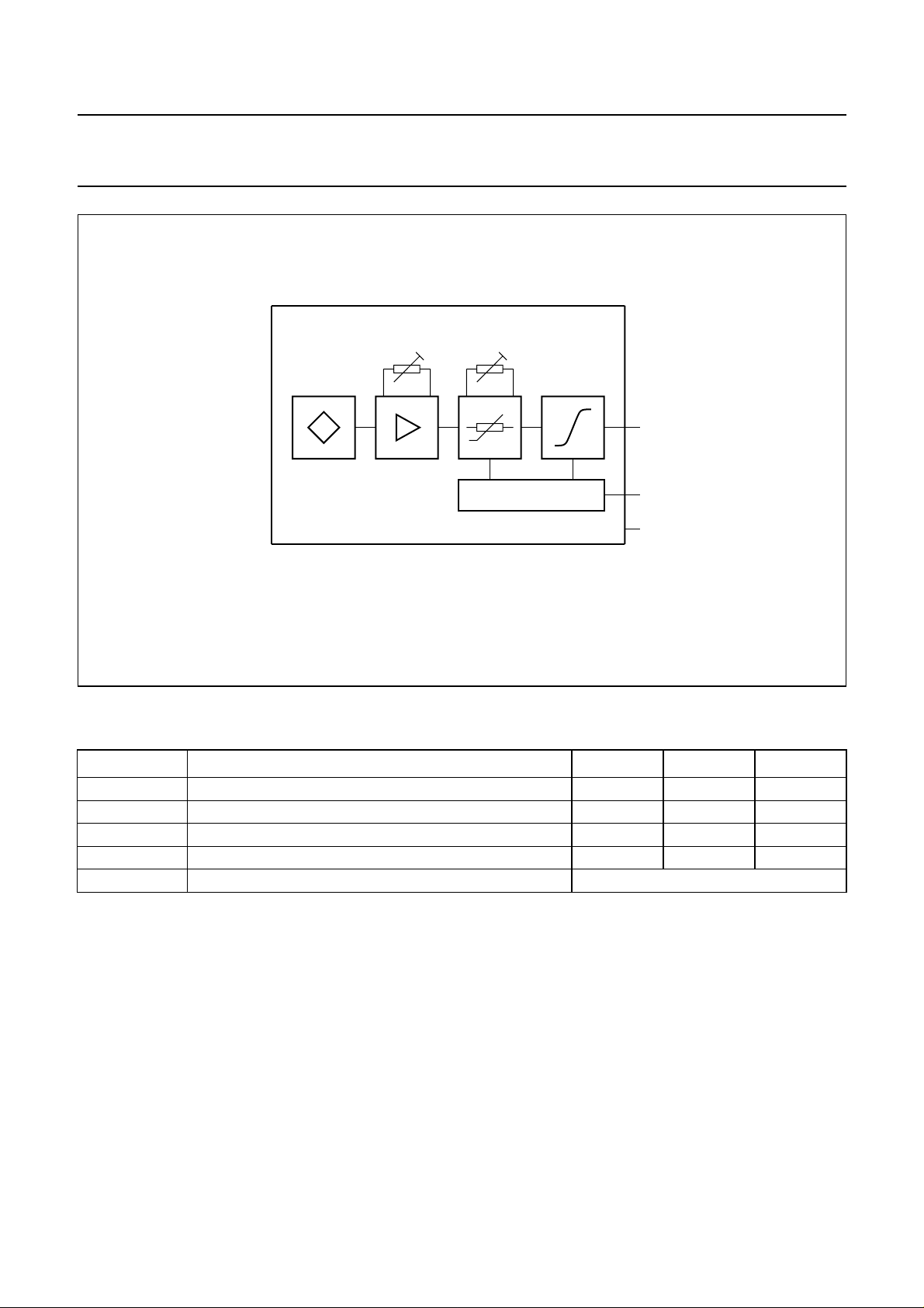
handbook, full pagewidth
sensor
angle
range
temperature
compensation
VOLTAGE CONTROL
Fig.2 Circuit diagram.
LIMITING VALUES
In accordance with the Absolute Maximum Rating System (IEC 134).
current
interface
MBD061
I
O
V
CC
GND
SYMBOL PARAMETER MIN. MAX. UNIT
V
CC
I
CC
T
stg
T
op
DC supply voltage 8.1 11 V
supply current − 40 mA
storage temperature −40 +125 °C
operating temperature −40 +100 °C
output short-circuit duration permanent; note 1
Note
1. If pin 3 is shorted to either pin 1 or pin 2, current may flow permanently, without damage to the device.
1998 Mar 26 3

Philips Semiconductors Product specification
Angle sensor hybrid circuit KM110BH/2270
CHARACTERISTICS
T
=25°C; VCC= 8.5 V and a homogeneous magnetic field H
amb
sensor; unless otherwise specified.
SYMBOL PARAMETER CONDITIONS MIN. TYP. MAX. UNIT
α angle range note 1 −−35 to +35 −46.5 to +46.5 deg
I
O
output current range note 2; sinusoidal;
see Fig.4
I
zero
I
offset
zero point current α =0°−12 − mA
zero point offset current −±120 −µA
S sensitivity α =0°; note 3 0.289 0.292 0.295 mA/deg
Rp reproducibility α =0°; note 4 − <0.001 − deg
Rs resolution α =0°; note 5 − <0.001 − deg
Rhy hysteresis α =0°; note 6 − <0.05 − deg
SP
R
max
L
maximum angular speed − 20 − deg/ms
load resistance − 200 220 Ω
Temperature coefficients (−40 to +85 °C)
TCI
zero
temperature coefficient of
zero point current
TCS temperature coefficient of
sensitivity
= 100 kA/m in the sensitive layer of the KMZ10B
ext
− 4 to 20 3.2 to 20.8 mA
−±1.5 −µA/K
−±100 − ppm/K
Notes
1. Refer to Fig.3. The magnetic field H
= 100 kA/m can be produced by using the magnets listed in Table 1.
ext
2. Maximum values refer to ±46.5° including offset and sensitivity tolerances.
3. The sensitivity will change slightly with +0.33% per 10% magnetic field increase if H
deviates from 100 kA/m.
ext
4. Difference in output signal (expressed in degrees) between two zero point (α = 0) measurements, in which the zero
point is approached from the same side of the measuring range (e.g. cycle: +35°→0°→+35°→0°).
5. The smallest detectable change of angle ∆α for α =0° (cycle: 0°→∆α).
6. As note 4, but with the zero point being approached from the upper end and lower end of the measuring range
respectively (cycle: +35°→0°→−35°→0°).
1998 Mar 26 4
 Loading...