

Page 1
Philips Lighting North America Corporation
200 Franklin Square Drive
Somerset, NJ 08873, USA
Phone: 855-486-2216
www.philips.com/luminaires
Philips Lighting Canada Ltd.
281 Hillmount Road,
Markham ON, Canada L6C 2S3
Phone: 800-668-9008
www.philips.com/luminaires
9140053295 February 2016
WARNING – Shut off AC power to branch
circuits to which units will be connected. All
wiring should be per N.E.C. wiring methods for
Hazardous locations.
To maintain warranty, equipment with batteries
must be installed or placed on charge within
prescribed period after shipment.
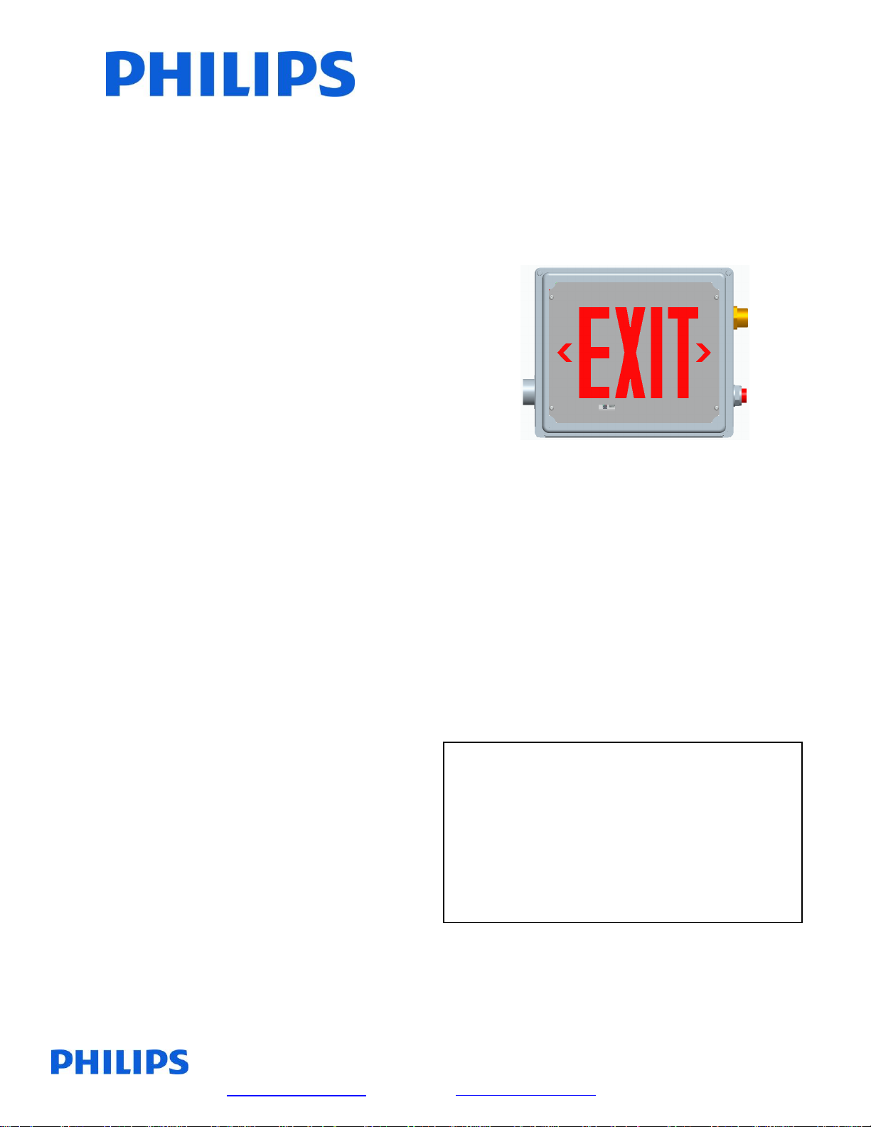
HZ SERIES
EMERGENCY LED EXIT
IMPORTANT
SAFEGUARDS
When using electrical equipment, basic safety
precautions should always be followed, including
the following:
READ AND FOLLOW ALL
SAFETY INSTRUCTIONS
All servicing should be performed by qualified
personnel only.
Do not mount near any heat producing equipment.
Equipment should be mounted in locations and at
heights where it will not be readily subjected to
tampering by unauthorized personnel.
The use of accessory equipment not recommended by
the manufacturer may cause an unsafe condition.
Do not use this equipment for other than intended use.
In Class I Division 2 locations, do not replace any
non-metallic hardware with metal hardware. Contact
authorized agent for factory replacement parts.
In Class I Division 2 areas, install equipment in
accordance with appropriate NEC articles plus any
other applicable codes.
To avoid static discharge, do not attach any ungrounded
metal hardware to the enclosure.
Do not use this equipment outdoors.
HAZARDOUS LOCATION
ZONE 2 GROUPS IIC, IIB AND IIA
CLASS II DIV 2 GROUPS F AND G
AND CLASS III DIV 1 AND 2
INSTALLATION AND OPERATING
CLASS I DIV 2
GROUPS A, B, C, AND D
INSTRUCTIONS
Install only grounded wiring systems to supply
this equipment.
Free installation area of hazardous atmospheres
before wiring equipment or servicing, this reduces
the risk of accidental explosion due to inadvertent
battery shorting during installation.
SAVE THESE
INSTRUCTIONS
Page 2
Philips Lighting North America Corporation
200 Franklin Square Drive
Somerset, NJ 08873, USA
Phone: 855-486-2216
www.philips.com/luminaires
Philips Lighting Canada Ltd.
281 Hillmount Road,
Markham ON, Canada L6C 2S3
Phone: 800-668-9008
www.philips.com/luminaires
9140053295 February 2016
Black Wire
- 120V Line
Blue Wire
- 277V Line
White Wire
- Common
White Wire
- Common
Green Wire
- Ground
Green Wire
- Ground
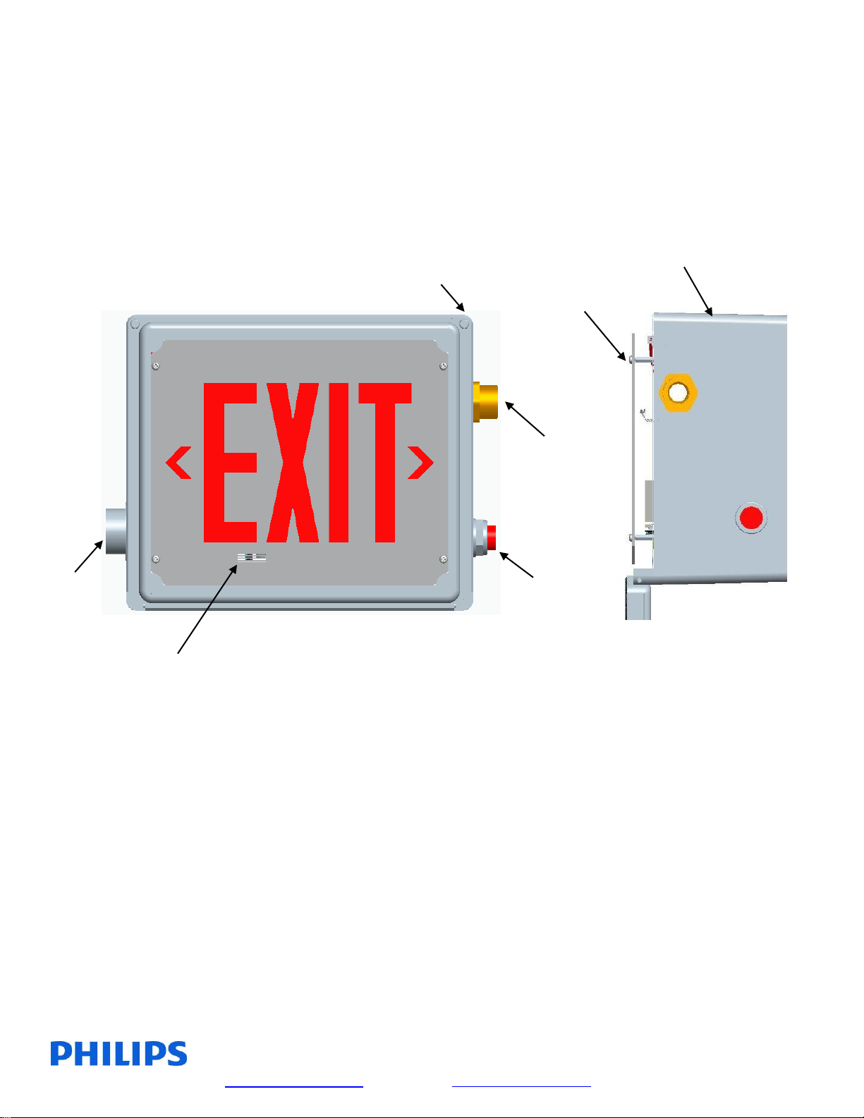
INSTRUCTIONS – INSTALLATION
1. Mount exit enclosure to wall using (4) thru holes or optional mounting feet. (See Figure 3).
2. Remove cover screws (2) and open cover. (See Figures 1 and 2).
3. Dismount exit lens by removing lens screws (4). (See Figures 1 and 2).
4. Connect ¾” conduit supply to ¾” hub on unit.
5. Hookup AC service to the connector assembly as follows:
Enclosure
Cover Screws (2)
Lens Screws (4)
¾” Hub
Vent Test Switch
Figure 1 Figure 2
AC/Charge IR Receiver
Status Indicator
120 VAC OPERATION 277 VAC OPERATION
Unused primary wire must be insulated to prevent shorting.
Page 3

Philips Lighting North America Corporation
200 Franklin Square Drive
Somerset, NJ 08873, USA
Phone: 855-486-2216
www.philips.com/luminaires
Philips Lighting Canada Ltd.
281 Hillmount Road,
Markham ON, Canada L6C 2S3
Phone: 800-668-9008
www.philips.com/luminaires
9140053295 February 2016
FIGURE 3
6. Chevron labels with self-adhesive backing are supplied. Apply label(s) to exit lens as necessary.
7. Remount exit lens using lens screws. Close cover and secure with cover screws.
INSTRUCTIONS – OPERATION
1. Energize AC power to exit. Unit will initiate normal power-up sequence (See page 4).
Page 4

Philips Lighting North America Corporation
200 Franklin Square Drive
Somerset, NJ 08873, USA
Phone: 855-486-2216
www.philips.com/luminaires
Philips Lighting Canada Ltd.
281 Hillmount Road,
Markham ON, Canada L6C 2S3
Phone: 800-668-9008
www.philips.com/luminaires
9140053295 February 2016
Self Diagnostic System Operation – Emergency Light or EXIT Sign Products
Normal Power Up Sequence
At power up the red and green LED indicators will alternately flash for one to two seconds. Next the product will execute
a “Power Up Quick Test” causing the green LED indicator to flash rapidly. If any faults are detected during the “Power Up
Quick Test” these will be evident by a flashing red LED indicator. If the audible diagnostic option has been ordered, the
flashing red LED will be accompanied by a simultaneous beeping tone. (Note: A continuous rapid alternating Red/Green
flash with rapid beeping tone indicates 277V applied to 120V input lead. TURN OFF POWER IMMEDIATELY!)
Emergency Operation
Emergency operation occurs when AC power fails. The product remains in emergency operation until AC power is
restored or battery capacity is depleted. During emergency operation both red and green LED indicators are disabled.
User Interface
Green LED indicator
Slow Flash/Continuous ON = AC power present; normal operating condition
Rapid Flash = product performing an automatic or manually initiated diagnostic test
Red LED indicator
Single Flash = battery fault
Two Flashes = lamp failure (light bar failure – EXIT signs)
Three Flashes = charger fault
Four Flashes = transfer fault
(If more than one fault condition is present simultaneously, the red LED will flash the indication pattern for each
fault independently then repeat the cycle.)
Pushbutton Test Switch
Long Press (longer than 0.5sec) transfers product to emergency operation during time the button is
pressed.
Short Press initiates self diagnostic activities as follows:
One Press cancels diagnostic test presently running.
Two Presses starts a one minute diagnostic test.
Three Presses starts a 90 minute diagnostic test.
Four Presses conducts a lamp load calibration (emergency light products only).
Seven Presses initiates a system reset.
(Note: the microprocessor will allow up to seven, one minute diagnostic tests within the first 24 hours of
operation. Allow 24 hours of charging before performing any long duration testing.)
Buzzer (optional)– Sounds in unison with the flashing red LED if a fault condition is present. Buzzer may be
silenced for up to 196 hours by a short press of either the test switch or the optional IR remote control device
“silence” button. Correcting fault condition will cancel fault notification. Lamp failure indication requires a
manually activated diagnostic test after lamp replacement to cancel notification.
IR Remote Control (optional)- is a hand held device that allows remote activation of diagnostic testing and
silencing of the optional buzzer during fault conditions.
Page 5

Philips Lighting North America Corporation
200 Franklin Square Drive
Somerset, NJ 08873, USA
Phone: 855-486-2216
www.philips.com/luminaires
Philips Lighting Canada Ltd.
281 Hillmount Road,
Markham ON, Canada L6C 2S3
Phone: 800-668-9008
www.philips.com/luminaires
9140053295 February 2016
 Loading...