

Philips hudson iv 170x5, 190X5FB/20, 190X5FB/00 Service Manual
Horizontal Frequencies
30 - 82KHz
Service
Service
Service
TABLE OF CONTENTS
Published by BCU Monitors Printed in Suzhou Copyright reserved Subject to modification H Aug. 6 2004
HUDSON IV 170X5
REFER TO BACK COVER FOR IMPORTANT SAFETY GUIDELINES
CAUTION: USE A SEPARATE ISOLATION TRANSFORMER FOR THIS UNIT WHEN SERVICING.
ANY PERSON ATTEMPTING TO SERVICE THIS CHASSIS MUST FAMILIARIZE HIMSELF WITH THE CHASSIS
AND BE AWARE OF THE NECESSARY SAFETY PRECAUTIONS TO BE USED WHEN SERVICING ELECTRONIC
EQUIPMENT CONTAINING HIGH VOLTAGES.
SAFETY NOTICE
GB
3138 106 10404
17" TFT LCD Monitor
Model: 170X5FB/00
Description Page
Important Safety Notice ----------------------------------2
Technical Data ------------------------------------------3~5
On-Screen Display ----------------------------------- 9 10
Electrical Instructions ------------------------------12
Mechanical Instructions ---------------------------14~15
Factory Mode ---------------------------------------------16
Troubleshooting ------------------------------------------- 6
Installations --------------------------------------------- 7~8
~
~13
Aging Mode ----------------------------------------------- 17
Repair Flow Chart -----------------------------------18~20
Safety Test Requirement ------------------------------- 21
Repair Tips ------------------------------------------------22
Wiring Diagram -------------------------------------------23
Function Block Diagram -------------------------------- 24
Scaler Schematic Diagram ------------------------25~30
Philips Pixel Defect Policy ------------------------------11
Description Page
------------------------------------------- 44
Scaler Board C.B.A. ------------------------------- 31~32
Control Schematic Diagram & C.B.A. ---------------33
Audio Schematic Diagram ------------------------34~35
Audio Board C.B.A. --------------------------------36~37
Earphone Schematic Diagram & C.B.A. ------------38
Power Schematic Diagram------------------------39~40
Power Board C.B.A. ------------------------------- 41 ~43
Exploded View
Spare Parts List------------------------------------ 45~ 47
Recommended Parts List ----------------------------- 48
General Product Specification-------------------49~73
ISP Cable For CPU --------------------------------74~76
DDC Instructions & DDC Data -------------------77~86
Failure Mode Of Panel----------------------------------87
~90
Warning Message--------------------------------------- 91
LightFrame for Windows ------------------------ 88
Different Parts List ------------------------------------- 92
«
TM
Proper service and repair is important to the safe, reliable
operation of all Philips Consumer Electronics Company**
Equipment. The service procedures recommended by
Philips and described in this service manual are effective
methodsofperformingserviceoperations.Someofthese
service operations require the use of tools specially designed
forthepurpose.Thespecialtoolsshouldbeusedwhenand
as recommended.
Itisimportanttonotethatthismanualcontainsvarious
CAUTIONSandNOTICESwhichshouldbecarefullyreadin
order to minimize the risk of personal injury to service
personnel. The possibility exists that improper service
methods may damage the equipment. It is also important to
understand that these CAUTIONS and NOTICES ARE NOT
EXHAUSTIVE. Philips could not possibly know, evaluate and
advisetheservicetradeofallconceivablewaysinwhich
service might be done or of the possible hazardous
consequences of each way. Consequently, Philips has not
undertaken any such broad evaluation. Accordingly, a
servicer who uses a service procedure or tool which is not
recommended by Philips must first satisfy himself thoroughly
thatneitherhissafetynorthesafeoperationofthe
equipment will be jeopardized by the service method
selected.
* *Hereafter throughout this manual, Philips Consumer
Electronics Company will be referred to as Philips.
Critical components having special safety characteristics are
identifiedwitha bytheRef.No.inthepartslistand
enclosed within a broken line*
(where several critical components are grouped in one area)
along with the safety symbol on the schematics or
exploded views.
Use of substitute replacement parts which do not have the
same specified safety characteristics may create shock, fire,
or other hazards.
Under no circumstances should the original design be
modified or altered without written permission from Philips.
Philips assumes no liability, express or implied, arising out of
any unauthorized modification of design.
Servicer assumes all liability.
WARNING
* Broken Line
FOR PRODUCTS CONTAINING LASER :
Invisible laser radiation when open.
AVOIDDIRECTEXPOSURETOBEAM.
Use of controls or adjustments or
performance of procedures other than
those specified herein may result in
hazardous radiation exposure.
The use of optical instruments with this
product will increase eye hazard.
DANGER-
CAUTION-
CAUTION-
TO ENSURE THE CONTINUED RELIABILITY OF THIS
PRODUCT, USE ONLY ORIGINAL MANUFACTURER'S REPLACEMENT
PARTS, WHICH ARE LISTED WITH THEIR
PARTNUMBERSINTHEPARTSLISTSECTIONOFTHISSERVICE
MANUAL.
Take care during handling the LCD module with backlight unit
- Must mount the module using mounting holes arranged in four
corners.
-Donotpressonthepanel,edgeoftheframestronglyorelectric
shock as this will result in damage to the screen.
- Do not scratch or press on the panel with any sharp objects, such
as pencil or pen as this may result in damage to the panel.
- Protect the module from the ESD as it may damage the electronic
circuit (C-MOS).
- Make certain that treatment person s body are grounded through
wrist band.
-Donotleavethemoduleinhightemperatureandinareasofhigh
humidityforalongtime.
-Avoidcontactwithwaterasitmayashortcircuitwithinthe
module.
-Ifthesurfaceofpanelbecomedirty,pleasewipeitoffwithasoft
material. (Cleaning with a dirty or rough cloth may damage the
panel.)
Important Safety Notice
!
!
2
170X5 LCD
Go to cover page

Go to cover page
170X5 LCD
3
Technical Data
Product Features
Outstanding front of screen performance
Design that complements any interior
Great convenience
LightFrame Digital Reality maximizes multimedia experence
Zero Bright Dot eliminates LCD bright dot defects
SXGA 1280 X 1024 resolution for sharper display
Fast response time capable of handling fast moving pictures
sRGB ensures color matching between display and printouts
Exclusive, elegant, design that complements fine home decor
Ultra-modern LightTouch controls
Dual Input accepts both analog VGA and digital * DVI signals
(*available for 170X5FB/00)
Enjoy multimedia experience from built-in speakers
Play music from external audio devices even if the PC is off
Embedded power supply eliminates external power adaptors
CableGuide keeps cables in order and your space neat
Auto adjustment for perfect picture display with one touch
Easily adjust display settings with Philips SmartControl
Screen tilts for comfortable viewing from any angle
Technical Specifications*
LCD PANEL
SCANNING
VIDEO
Audio
Type TFT LCD
Screen size 17" /43.2 cm diagonal
Pixel Pitch 0.264 x 0.264 mm
1280 x 1024 pixels
R.G.B. vertical stripe
Anti-glare polarizer, hard coated
Ef fective viewing area 337.9 x270.3 mm
Display Colors 16M colors
Vertical refresh rate 56 Hz-76 Hz
Horizontal Frequency 30 kHz-82 kHz
V ideo dot rate 135 MHz
Input impedance
- Video 75 ohm
- Sync 2.2K ohm
Input signal levels 0.7 Vpp
Sync input signal
Sync polarities Positive and negative
Video interface Dial input: D-sub (analog) and
DVI-D (digital) (170X5/00)a
available and user selectable
Light Frame Brightness and sharpness
LCD Panel type
Separate sync
Composite sync
Sync on green
re
Enhancement
Loudspeaker 4W Stereo Audio (2W/channel
RMSx2, 300Hz-14kHz, 16 ohm,
THD=10%, PMPO 32 Watts)
Headphone connector 3.
5 mm mini jack
Input signal connector 3.5 mm mini jack
Resolution & Preset Modes
16 user definable modes
Maximum 1280 X 1024 at 75Hz
Recommended 1280 X 1024 at 60 Hz
16 factory preset modes:
TM
Whether there is a video display or not
as long as there is an audio input, the
audio output is always functional.
Stand-alone audio output Note: The volume adjustment can not
function under the following conditions:
1. A warning message appears on screen
2. No audio input
Contrast ratio 450:1 (typ.)
Brightness 260 cd/m (typ.)
Peak contrast angle 6 o'clock
x: 0.283y:0.297(at 9300 K)
White Chromaticity x: 0.313y:0.329 (at 6500 K)
x: 0.313y:0.329 (at sRGB)
Upper 70 (typ.)
Viewing Angle(C/R>=5) Lower 70 (typ.)
Left 80 (typ.)
Right 80 (typ.)
Response time 16 ms (typ.)
sRGB is a standard
Optical Characteristics
SRGB
for ensuring correct exchange of colors between
different devices (e.g. digital cameras, monitors, printers, scanners, etc.)
Using a standard unified color space, sRGB will help represent pictures
taken by an sRGB compatible device correctly on your sRGB enabled
Philips monitors. In that way, the colors are calibrated and you can rely
on the correctness of the colors shown on your screen.
Important with the use of sRGB is that the brightness and contrast of
your monitor is fixed to a predefined setting as well as the color gamut.
Therefore it is important to select the sRGB setting in the monitor's OSD.
To do so, open the OSD by pressing the OK button on the front of your
monitor. Use the down button to go to Adjust Color and press OK again.
Then move the down button to go to sRGB and press OK again.
After this, please do not change the brightness or contrast setting of your
monitor. If you change either of these, the monitor will exit the sRGB
mode and go to a color temperature setting of 6500K.
For more information on sRGB, please visit: www.srgb.com
2
O
O
O
O
O
O
31.5 640*350 70
31.5720*400 70
31.5 640*480 60
35.0 640*480 67
37.5 640*480 75
31.3 688*556 50
H. Freq (kHz) Resolution V. freq (Hz)
TM
4
170X5 LCD
Go to cover page
Technical Data
R
R
R
Physical Specification
Dimension (W XHXD)* 388 x 400 x181 mm (in lowest position)
Weight 5.5Kg
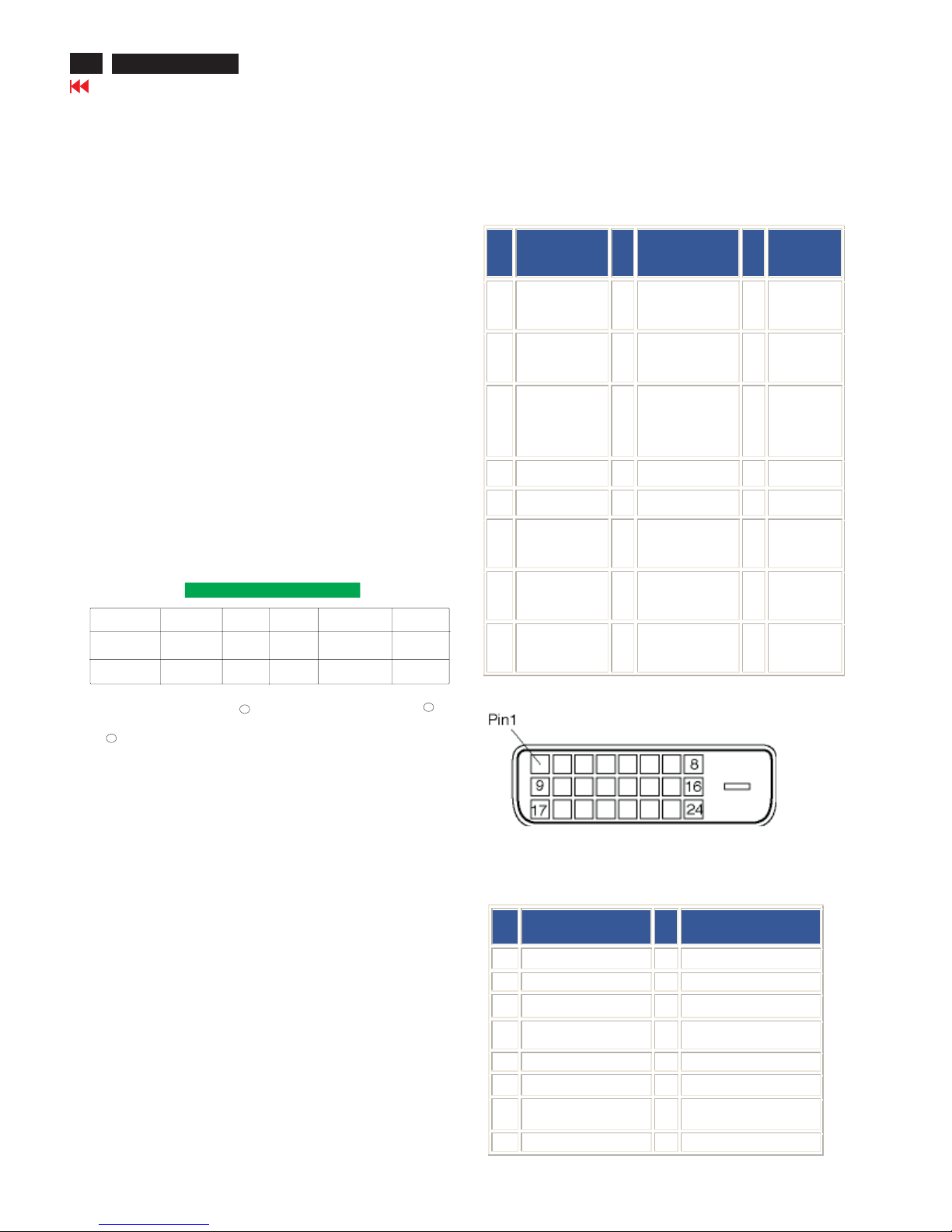
Tilt -5 --25
Power Supply 100 ---240VAC, 50/60 Hz
Power consumption 35 W* (typ.)
Temperature 5 Cto40 C (operating)
-20 Cto60 C (storage)
Relative humidity 20% to 80%
System MTBF 50K hours (excluding CCFL 40K hours)
Cabinet color Black
*This data is subject to change without notice.
*Resolution 1280 X 1024, standard size, brightness max., Contrast 50%,
9300 K, full white pattern, without audio.
O
O
O
O
O
O
Automatic Power Saving
If you have VESA DPMS compliance display card or software installed in
your PC, the monitor can automatically reduce its power consumption
when not in use. If an input from a keyboard, mouse or other input device
is detected, the monitor will 'wake up' automatically. The following table
shows the power consumption and signaling of this automatic power
saving feature:
VESA Mode Video H-sync V-sync Power Used LED color
ON Active Yes Yes <45W Green
OFF Blanked No No <1W Amber
This monitor is ENERGY STAR compliant. As an ENERGY STAR
Partner, PHILIPS has determined that this product meets the ENERGY
STAR guidelines for energy efficiency.
Power Management Definition
35.2 800*600 56
37.9 800*600 60
46.9 800*600 75
49.7832*62475
48.41024*768 60
60.01024*768 75
69.01152*870 75
71.81152*900 76
63.91280*102460
80.01280*102475
O
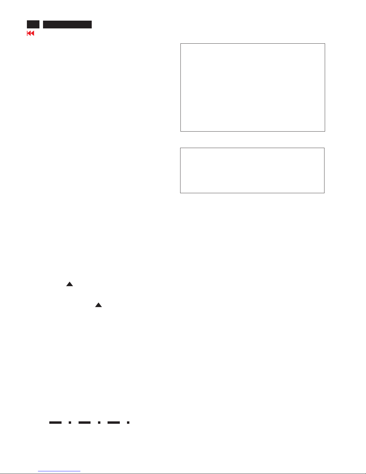
Pin Assignment
1. The digital only connector contains 24 signal conta c ts
organized in three rows of eight contacts. Signal pin
assignments are listed in the following table:
Pin
No.
Signal
Assignment
Pin
No.
Signal Assignment
Pin
No.
Signal
Assignment
1 T.M.D.S. Data2- 9 T. M.D .S . Dat a1- 17
T.M. D. S.
Data0-
2 T.M. D. S. D ata 2+ 10 T.M. D. S. D ata 1+ 18
T.M. D. S.
Data0+
3
T.M. D. S. D at a2/4
Shield
11
T.M. D. S. D at a1/3
Shield
19
T.M. D. S.
Data0/5
Shield
4 No connect 12 No connect 20 No connect
5 No connect 13 No connect 21 No connect
6 DDC Clock 14 +5V Power 22
T.M. D. S.
Clock Shield
7 DDC Data 15 Ground (for +5V) 23
T.M. D. S.
Clock+
8 No connect 16 Hot Plug Detect 24
T.M. D. S.
Clock-
2. The 15-pin D-sub connector (male) of the signal cable:
Pin
No.
Assignment
Pin
No.
Assignment
1 Red video input 9 +5V
2 Green video input/SOG 10 Logic ground
3 Blue video input 11 Ground
4 Sense (GND) 12 Serial data line (SDA)
5 Hot Plug Detect 13 H. Sync / H+V
6 Red video ground 14 V. Syn c ( VC LK for DDC)
7 Green video ground 15 Data clock line (SCL)
8 Blue video ground
Go to cover page
5
170X5 LCD
Technical Data
Physical Function
Tilt
Energy Star Declaration
PHILIPS
170X5FS
PHILIPS
This monitor is equipped with a function for saving energy which
supports the VESA Display Power Management Signaling (DPMS)
standard. This means that the monitor must be connected to a
computer which supports VESA DPMS to fulfill the requirements
in the NUTEK specification 803299/94. Time settings are
adjusted from the system unit by software.
NUTEK VESA State LED Indicator Power Consumption
Normal operation ON Green <45W
Power Saving
Alternative 2 OFF Amber <1W
One step
As an ENERGY STAR Partner, has
determined that this product meets the
ENERGY STAR guidelines for energy
efficiency.
R
R
Troubleshooting
6
Go to cover page
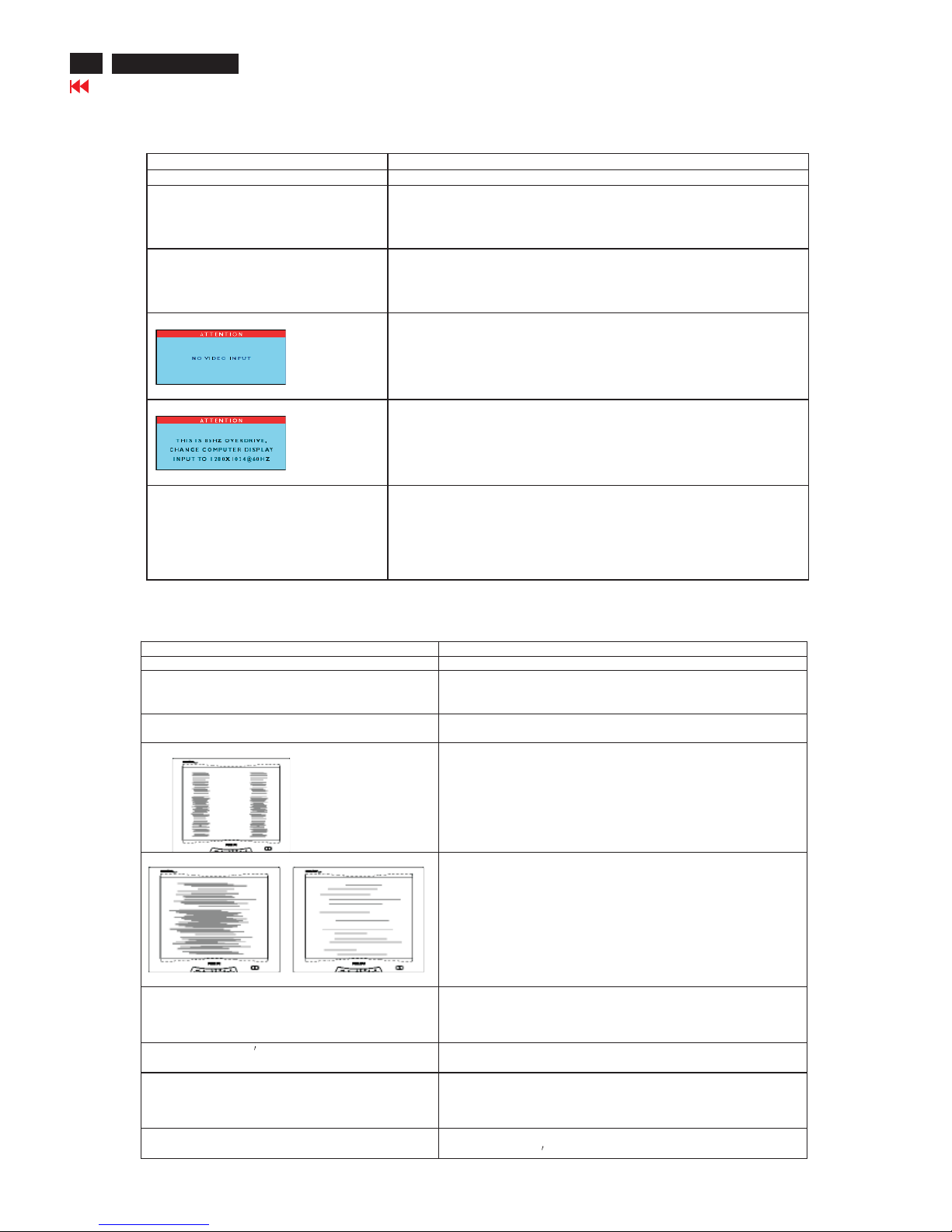
Common Probl ems
Having this problem? Check these items
No Picture
(power LED not lit)
· Make sure the power cord is plugged into the power outlet
and into the back of the monitor.
· First, ensure that the power button on the front of the monitor is in
the OFF position, then press it to the ON position
No Picture
(Power LED is amber or yellow)
· Make sure the computer is turned on.
· Make sure the signal cable is properly connected to your computer.
· Check to see if the monitor cable has bent pins.
· The Energy Saving feature may be activated
Screen says
· Make sure the monitor cable properly connected to your computer.
(Also refer to the Quick Set-Up Guide).
· Check to see if the monitor cable has bent pins,
· Make sure the computer is turned on.
Screen says
· Make sure the vertical sync of input signal is within the range of
56--75Hz.
· Change the refresh rate to 56--75Hz within 10 minutes.
· Re-power on monitor to start over again if you failed to change the
refresh rate within 10 minutes.
AUTO button not working properly
· The Auto Function is designed for use on standard Macintosh or
IBM-compatible PCs running Microsoft Windows.
· It may not work properly if using nonstandard PC or video card.
· The AUTO adjustment does not function when digital is used for
display.
This page deals with problems that can be corrected by the user.
170X5 LCD
Image Problems
Having this problem? Check these items
Display position is incorrect
· Press the AUTO button
· Adjust the image position using the Horizontal Position
and/or Vertical Position in OSD Main Controls.
Image vibrates on the screen
· Check that the signal cable is properly connected to the
graphics board or PC.
Vertical flicker appears
· Press the AUTO button
· Eliminate the vertical bars usin g the Clock Adjustment of
VIDEO NOISE in OSD Main Controls.
Horizontal flicker appears
· Press the AUTO button
· Eliminate the horizontal bars using the Phase
Adjustment of VIDEO NOISE in OSD Main Controls.
The screen is too bright or too dark
· Adjust the contrast and brightness on OSD Main Controls. (The
backlight of the LCD monitor has a fixed life span. When the
screen becomes dark or begins to flicker, please contact your
dealer).
LightFrame doesn twork. · Press the Auto button.
· Activate the LightFrame software again.
An after-image remains after the power has
been turned off.
· This is characteristic of liquid crystal and is not caused by a
malfunction or deterioration of the liquid crystal. The after-image
will disappear after a period of time.
Green, red, blue, and white dots remains
· The remaining dots are normal characteristic of the liquid crystal
used in today
s technology.
TM
TM
Go to cover page
7
Installations
170X5 LCD
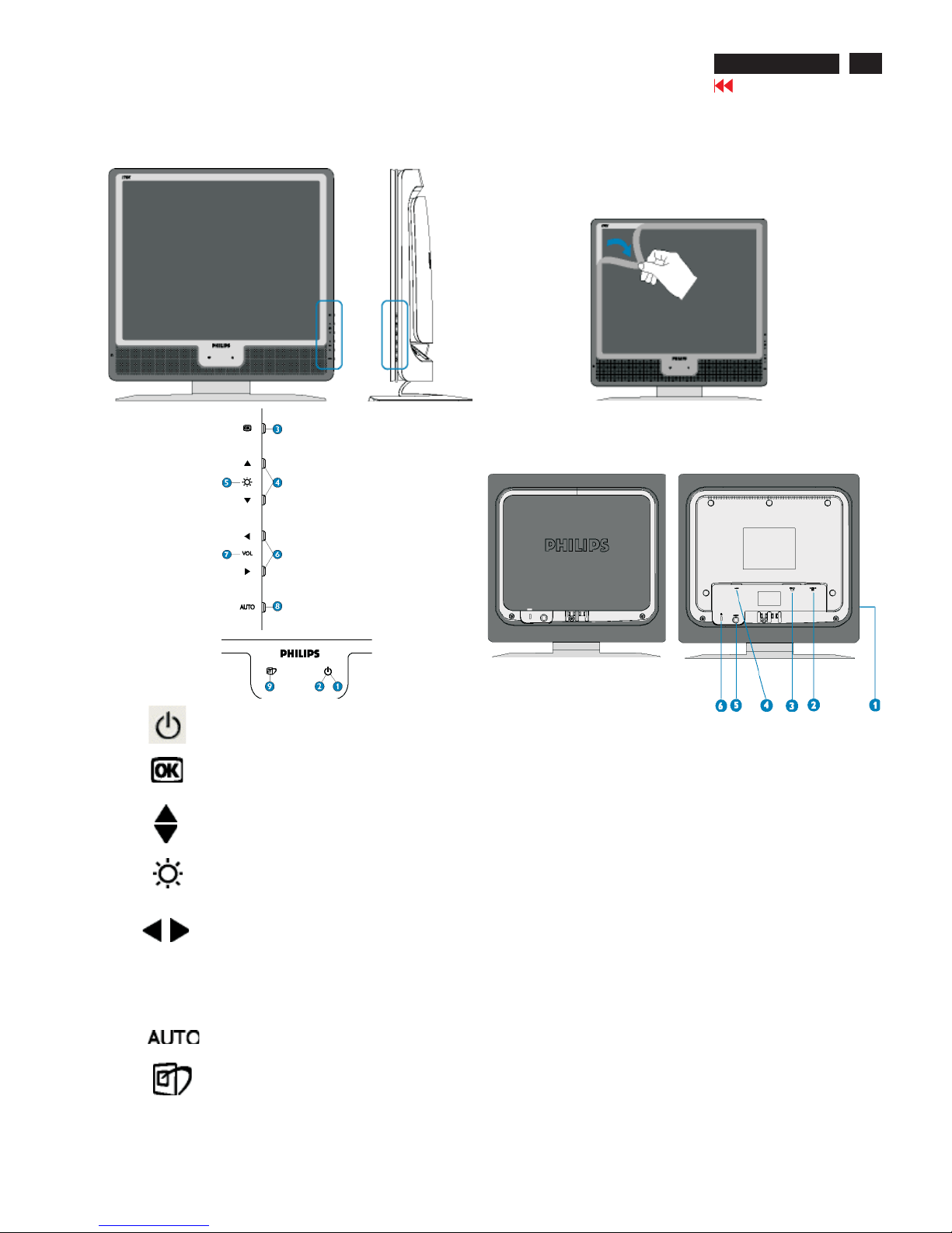
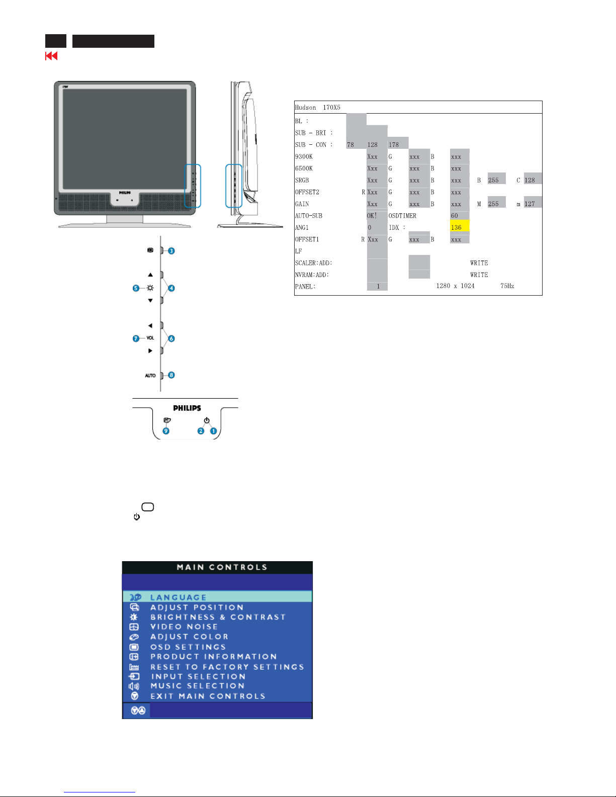
1. Power button switches your monitor on.
2. Power LED
3. OK button which when pressed will take you to the
OSD controls.
4. UP and DOWN buttons are used when adjusting the
OSD of your monitor.
BRIGHTNESS hotkey. When the UP and DOWN
arrow buttons are pressed, the adjustment controls
for the BRIGHTNESS will show up.
LEFT and RIGHT buttons, like the UP and DOWN
6. Buttons, are also used in adjusting the OSD of your
monitor.
VOLUME hotkey. When the LEFT and RIGHT arrow
7. buttons are pressed, the adjustment controls for
VOLUME will show up.
8. Automatically adjust the horizontal position, vertical
position, phase and clock setting.
9. LightFrame hotkey to select full-screen modes
among Internet, Photo and Video-TV.
VOLUME
5.
Remove protective film
A special film protects the screen frame of your new Philips monitor
during transit. Please remove the protective film from the screen before
using your monitor.
Front View Product Description
Rear View
1 Earphone jack (on side)
2 VGA input
3 DVI-D input (available for 170X5FB/00)
4 AC power input
5 PC audio input
6Kensington anti-thief lock
TM

8
Go to cover page
Installations
170X5 LCD
Connecting your monitor
1)
2)
3)
Cable management
4)
If you use an Apple Macintosh, you need to connect
the special Mac adapter to one end of the monitor
signal cable.
5) connect to PC
(1)
(2)
(3)
(4)
Turn off your computer and unplug its power cable.
Connect the monitor signal cable to the video connector on the
back of your computer.
Plug the power cord of your computer and your monitor into a
nearby outlet.
Turn on your computer and monitor. If the monitor displays an
image, installation is complete.
Go to cover page
9
On-Screen Display
170X5 LCD
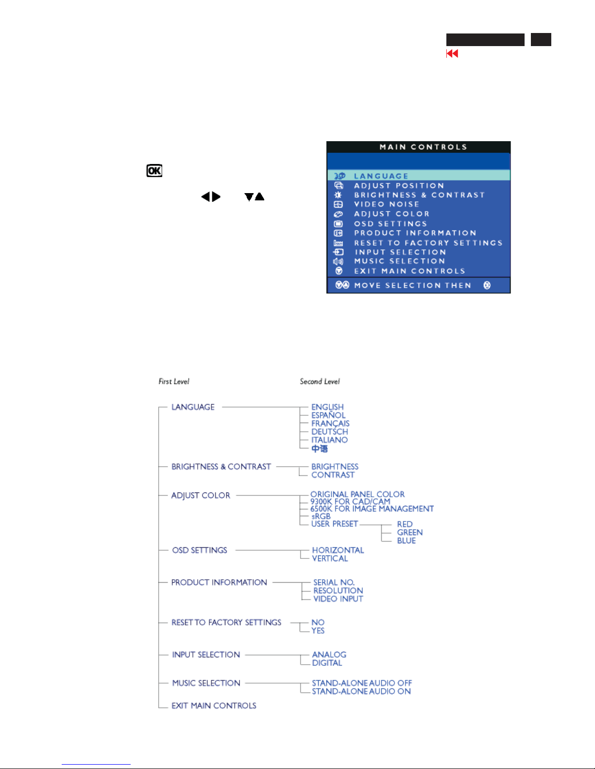
Description of the On Screen Display
What is the On-Screen Display?
This is a feature in all Philips LCD monitors. It allows an end user to adjust screen performance of
the monitors directly through an on-screen instruction window. The user interface provides userfriendliness
and ease-of-use when operating the monitor.
Basic and simple instruction on the control keys.
When you press the button on the front control of your
monitor, the On-Screen Display (OSD) Main Controls window
will pop up and you can then start making adjustments to your
monitor'svarious features. Use the or the keys to
make your adjustments.
The OSD Tree
Below is an overall view of the structure of the On-Screen Display.
You can use this as a reference when you want to work your way
around the different adjustments later on.
Digital signal input: (170X5/00)
10
Go to cover page
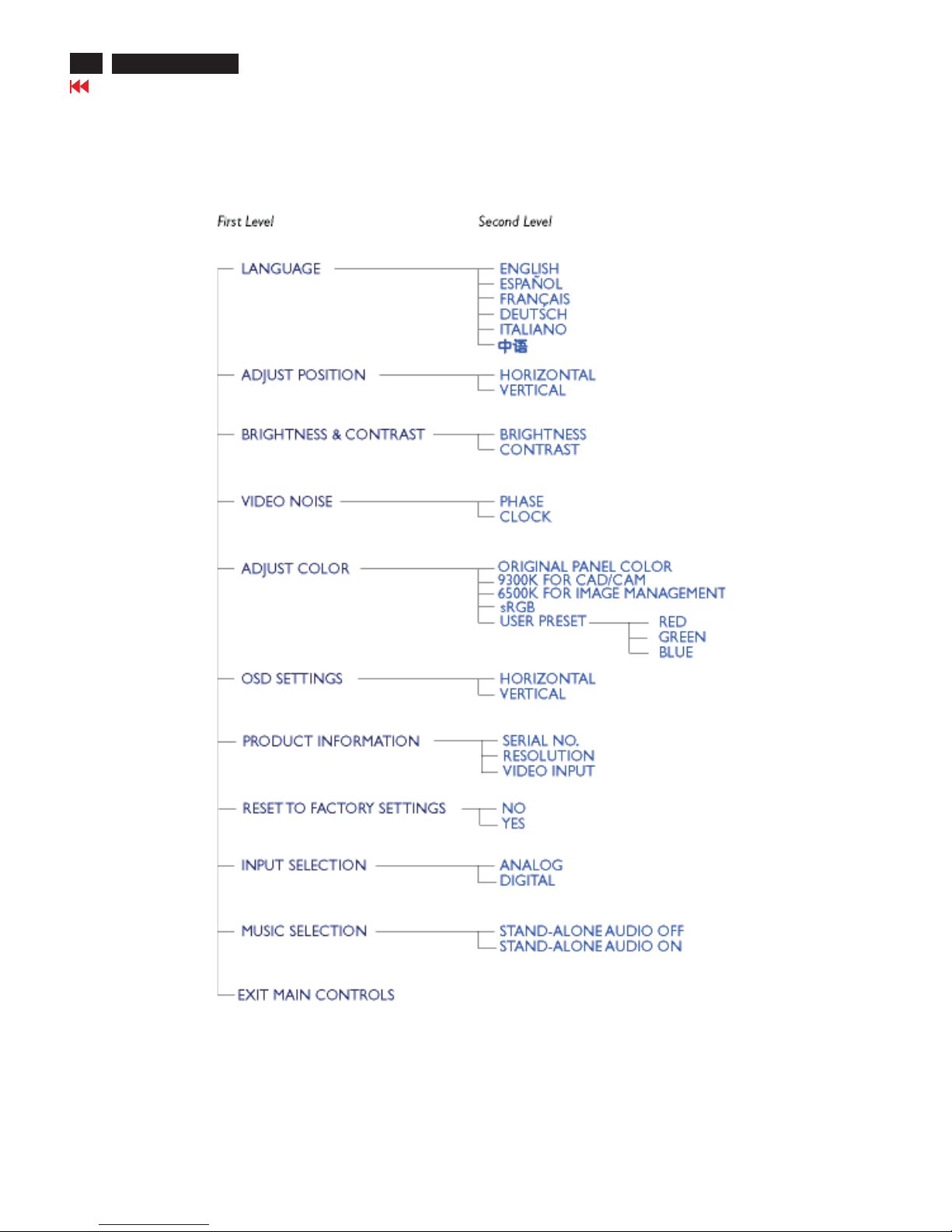
On-Screen Display
170X5 LCD
Analog signal input:
Philips' Flat Panel Monitors Pixel Defect Policy
Philips strives to deliver the highest quality products. We
use some of the industry's most advanced manufacturing
processes and practice stringent quality control. However,
pixel or sub pixel defects on the TFT LCD panels used in
flat panel monitors are sometimes unavoidable. No
manufacturer can guarantee that all panels will be free
from pixel defects, but Philips guarantees that any monitor
with an unacceptable number of defects will be repaired or
replaced under warranty. This notice explains the different
types of pixel defects and defines acceptable defect levels
for each type. In order to qualify for repair or replacement
under warranty, the number of pixel defects on a TFT LCD
panel must exceed these acceptable levels. For example,
no more than 0 .0004% of the sub pixels on a 15" XGA
monitor may be defective. Furthermore, Philips sets even
higher quality standards for certain types or combinations
of pixel defects that are more noticeable than others. This
policy is valid worldwide.
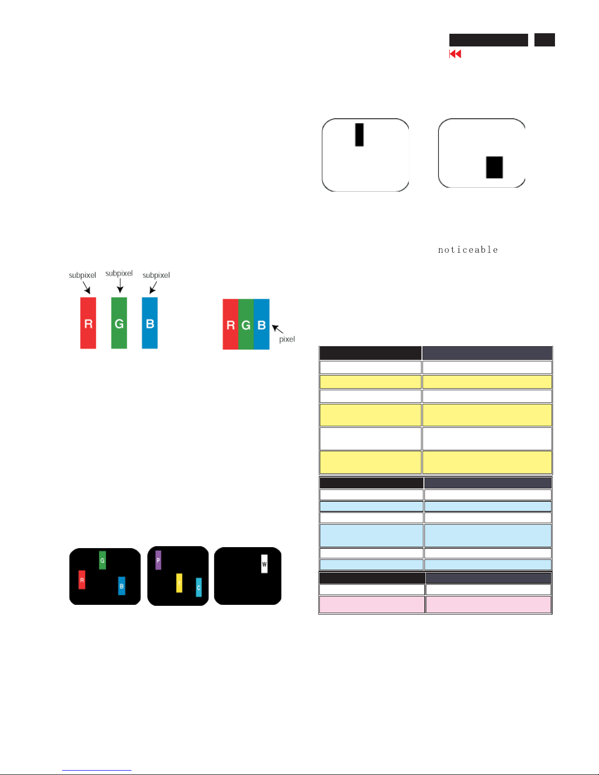
Pixels and Sub pixels
A pixel, or picture element, is composed of three sub pixels
in the primary colors of red, green and blue. Many pixels
together form an image. When all sub pixels of a pixel are lit,
the three colored sub pixels together appear as a single
white pixel. When all are dark, the three colored sub pixels
together appear as a single black pixel. Other combinations
of lit and dark sub pixels appear as single pixels of other
colors.
Types of Pixel Defects
Pixel and sub pixel defects appear on the screen in different
ways. There are two categories of pixel defects and several
types of sub pixel defects within each category. Bright dot
defects appear as pixels or sub pixels that are always lit or
'on'. These are the types of bright dot defects:
One lit red,
green or
blue sub pixel
Two adjacent lit
sub pixels:
- Red + Blue = Purple
- Red + Green = Yellow
- Green + Blue = Cyan
(Light Blue)
Three adjacent lit
sub pixels
(one white pixel)
Black Dot Defects Black dot defects appear as pixels or sub
pixels that are always dark or 'off'. These are the types of black
dot defects:
One dark sub pixel Two or three adjacent dark sub pixels
Proximity of Pixel Defects
Because pixel and sub pixels defects of the same type that are
near to one another may be more , Philips also
specifies tolerances for the proximity of pixel defects.
Pixel Defect Tolerances
In order to qualify for repair or replacement due to pixel defects
during the warranty period, a TFT LCD panel in a Philips flat panel
monitor must have pixel or sub pixel defects exceeding the
tolerances listed in the following tables.
Note:
* 1 or 2 adjacent sub pixel defects =1dot defect
All Philips monitors are ISO13406-2 Compliant
Philips Pixel Defect Policy
Go to cover page
11
170X5 LCD
BRIGHT DOT DEFECTS ACCEPTABLE LEVEL
MODEL
170X5
1 lit subpixel
0
2 adjacent lit subpixels
0
3 adjacent lit subpixels (one white
pixel)
0
Distance between two bright dot
defects*
Total bright dot defects of all types
BLACK DOT DEFECTS ACCEPTAB LE LEVEL
MODEL 170X5
1 dark subpixel 4 or fewer
2 adjacent dark subpixels 1 or fewer
3 adjacent dark subpixels 0
Distance between two black dot defects* 15 mm or more
Total black dot defect s of all types 4 or fewer
TOTAL DOT DEFECTS ACCEPTABLE LEVEL
MODEL 150C5
Total bright or black dot defects of all
types
5 or fewer
0
0

Electrical Instructions
12
170X5 LCD
Go to cover page
PRESET VIDEO RESOLUTION
# Resolution H-Frequency P ixel rate V-Frequency Comment
1 640X350 31.5K 25.175 70Hz IBM VGA 10h
2 720X400 31.5K 28.322 70Hz IBM VGA 3h
3640X480 31.5K 25.175 60Hz
4 640X480 35.0K 30.24 67Hz
5 640X480 37.9K 31.5 72Hz
6 640X480 37.5K 31.501 75Hz
7 640X480 43.3K 36 85Hz
8 800X600 35.2K 36 56Hz
9 800X600 37.9K 40 60Hz
10 800X600 48.1K5072Hz
11 800X600 46.9K 49.498 75Hz
12 800X600 53.7K 56.251 85Hz
13832X624 49.7K 57.28 75Hz MAC
14 1024X768 48.4K 65 60Hz
15 1024X768 56.5K 75 70Hz
16 1024X768 60.0K 78.75 75Hz
17 1024X768 61.1K 83.096 76Hz IBM XGA-2
18 1024X768 68.7K 94.5 85Hz
19 1152X864 54.0K 79.9 60Hz non-VESA
20 1152X864 67.5K 108 75Hz
21 1152X864 63.9K 94.5 70Hz non-VESA
22 1152X870 68.7K 100 75Hz MAC
23 1152X900 61.8K 92.94 66Hz SUN Mode IV
24 1152X900 71.8K 108 76Hz SUN Mode II
25 1280X960 60.0K 108 60Hz
26 1280X960 75.0K 129.895 75Hz non-VESA
27 1280X102464.0K 108 60Hz
28 1280X102471.7K 117 67Hz SUN Mode V
29 1280X102476.0K130.22372Hz DOS/V
30 1280X102480.0K 135 75Hz
311280X102481.1K 135. 008 76Hz SUN Mode I
32 688X556 31.3K 27 50Hz TV-PAL

Go to cover page
170X5 LCD
13
Electrical Instructions
9300°K 6500°K
x (center) 0.283 ± 0.020 0.313 ± 0.020
y (center) 0.297 ± 0.020 0.329 ± 0.020
sRGB
x(center) 0.313 ± 0.020
y(center) 0.329 ± 0.020
Ynits 180 ± 10
Dot rate (MHz) H. Freq (KHz) Mode Resolution V. Freq (Hz)
36.000 43. 269 VESA 640 * 480 85.008
56.250 53.674 VESA 800 * 600 85.061
94.500 68. 677 VESA 1024 * 768 84.997
3. Power Supply (S)
4. Display Adjustment
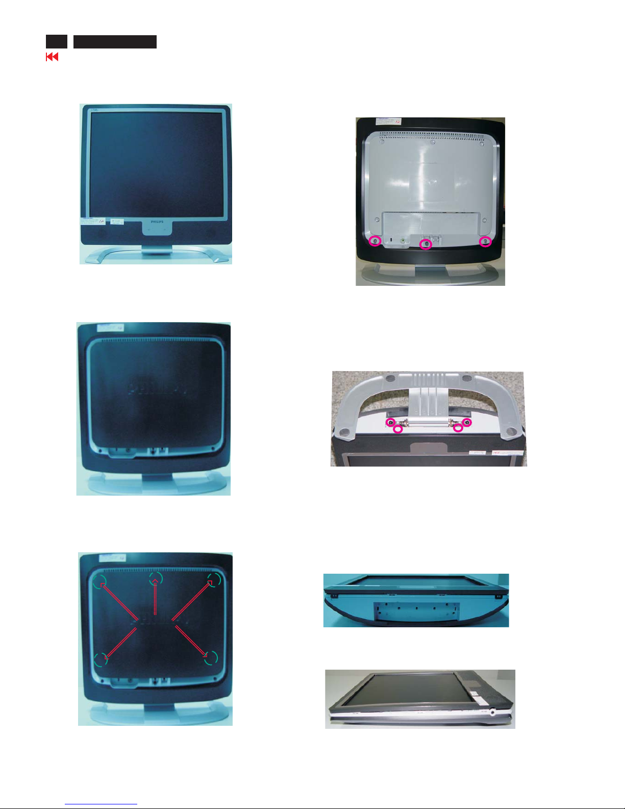
Mechanical Instructions
Front View
Back View
Step 3:
-Unscrew the four screws as shown in Fig. 5.
- Remove the base.
Fig. 1
Step 4: Remove the front bezel
- Use thin "l" type screwdriver to open 4 clicks on bottom
side as shown in Fig. 6.
- Use thin "l" type screwdriver to open 3 clicks on right
and left side as shown in Fig. 7.
- Use thin "l" type screwdriver to open 4 clicks on top
side as shown in Fig. 8.
Step 1: Use "l" type screwdriver to remove the Logo Cover as shown
in Fig. 3.
Fig. 3
=============>
97
313815413521
Logo Cover
Clip
Step 2: Unscrew 3 screws as shown in Fig. 4.
Fig. 4
Fig. 5
Fig. 6
========>
========>
========>
========>
14
170X5 LCD
Go to cover page
Fig. 7
======>
======>
======>
Mechanical Instructions
Go to cover page
170X5 LCD
15
1050 823827714781 TFT-LCD MOD LM170E01-A5KE
LCD Panel
***************************************************************************
In warranty, it is not allowed to disassembly the LCD panel, even the
backlight unit defect.
Out of warranty, the replacment of backlight unit is a correct way
when the defect is cused by backlight (CCFL,Lamp).
***************************************************************************
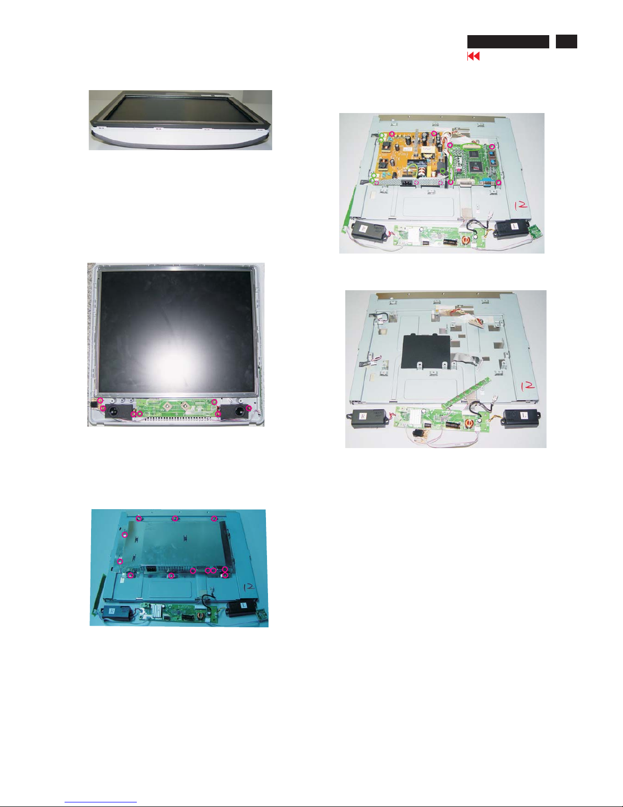
Fig. 8
======>
=======>
======>
======>
Step 5: Remove the Back Cover Assy
-Remove the Control Board from the Back Cover Assy
-Unscrew 7 screws as shown in Fig. 9.
-Remove Audio Assy, Earphone Assy and two LSP Box
from the Back Cover Assy
-Use thin "l" type screwdriver to open clicks on left side, right
side and up side, Remove LCD Panel from Back Cover Assy
shown in Fig. 9.as
<===
1054
313815859641
CONTROL ASSY
<======
1053
313815859651
AUDIO ASSY
<======
1049
313815859631
EARPHONE ASSY
Fig. 9
Step 6: Unscrew 12 screws as shown in Fig. 10.
Remove Shielding Cover
Fig. 10
Step 7: Unscrew 9 screws as shown in Fig. 11.
Disconnect 7 connectors as shown in Fig. 11.
Fig. 11
=======>
=======>
1051
313815859731
SCALER ASSY
1052
823827716021
LIPS(T50P054.00)
Fig. 12
16
Go to cover page
170X5 LCD
Factory Mode
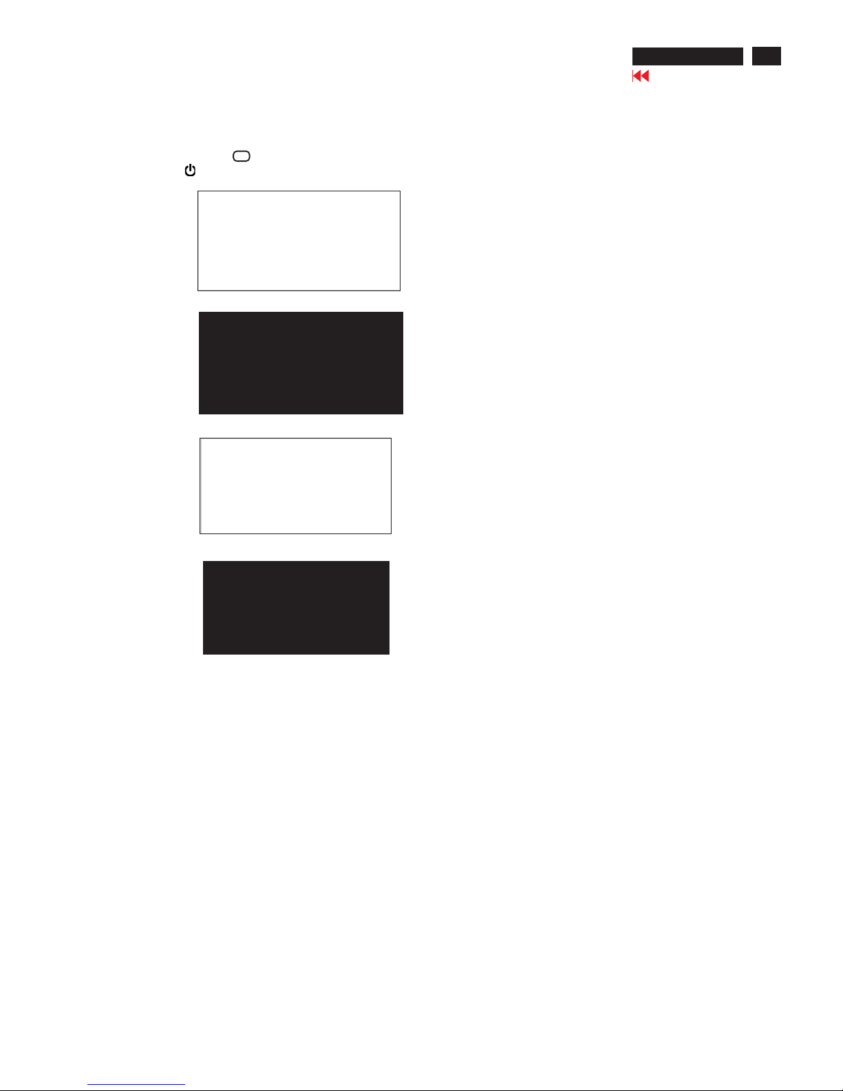
How to enter Factory Mode
1. Turn off the monitor.
2. [Push "AUTO " & "OK" buttons at the same time and hold it
] + [Press power " " button until comes out "Windows screen"]
=> then release all button, then press , wait until the
OSD menu with Characters "HUDSON4 170X5 V200 20040722"
(below OSD menu) come on the Screen of the monitor
(see Fig. 2).
"OK" button
Factory Mode
Indicator
HUDSON4 170X5 V200 20040722HUDSON4 170X5 V200 20040722
----------------->
0
50
255
VAL:
READ
VAL: READ
LG 17
Factory menu
Cursor can move on gray color area
BL : Blacklevel value
SUB-BRI : Brightness value range(Min Max)
SUB-CON : Contrast value range(Min Mid Max)
SRGB-B : Brightness of sRGBv
SRGB-C : Contrast of sRGB
Gain-m : Minimum value of User Gain
Gain-M : Maximum value of User Gain
AUTO-SUB: To do Auto color function when push Menu key in white pattern
OSDTIMER : OSD time out control(sec)
ANG1:For analog only project control (0:Dual, 1:Analog only)
IDX : Limit current of inverter
SCALER : Read/Write scaler register
NVRAM : Read/Write eeprom address
Panel : LG (LG. Philips panel)
Go to cover page
17
170X5 LCD
Aging Mode
AGING...
After 15 seconds,
bring up:
After 15 seconds,
bring up:
AGING...
After 15 seconds,
bring up:
----------
---------repeatly
Connect Signal cable again=> go back to normal display
How to Access Aging Mode
Step 1:Turn off LCD monitor, and disconnect Interface Cable between Monitor and PC.
Step 2:[Push "AUTO"&"OK"buttons at the same time and hold it]
+[Press power " " button untill comes out " AGING screen"] =>
then release all buttons.
Bring up:
18
Go to cover page
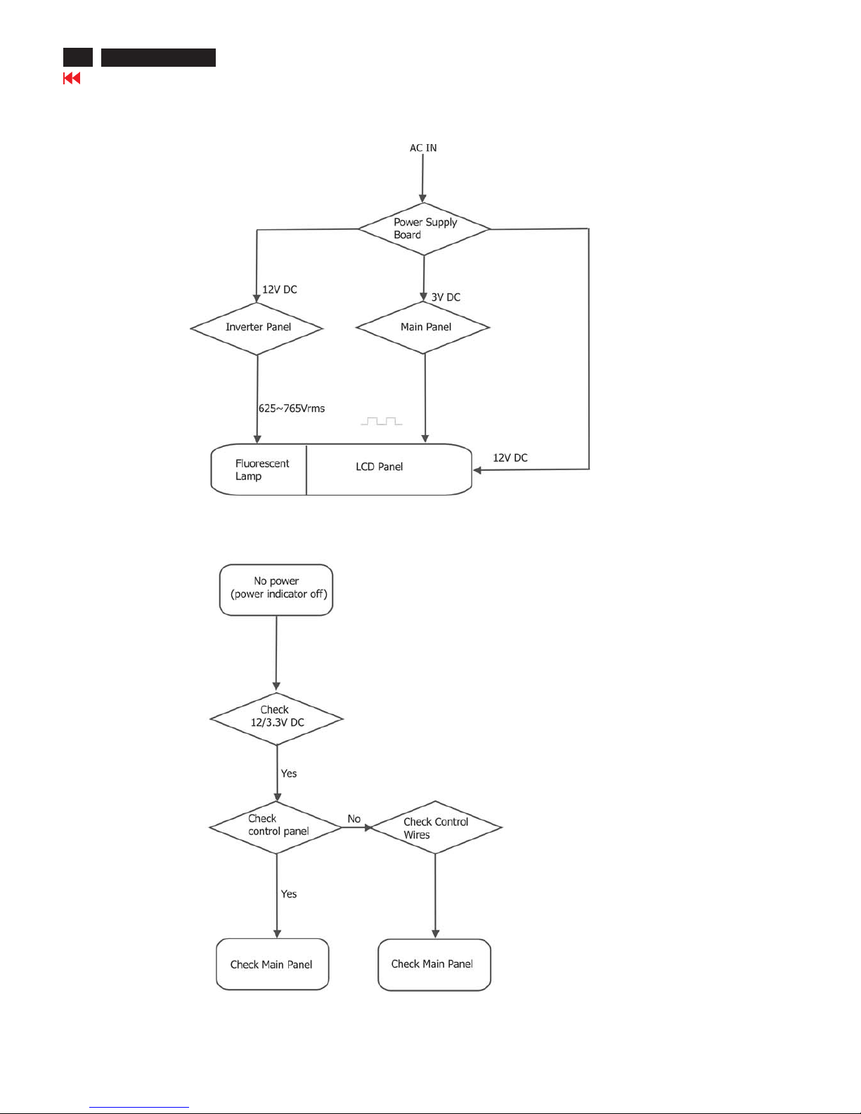
Repair Flow Chart
170X5 LCD

Go to cover page
19
No Display
Check Mains cord
& LED of Monitor
Check
Power board
12V/3.3V DC
Yes
No
Check
video signals input
interface
Video source
Yes
No
No
OK
Check
Inverter panel
625~765Vrms with load
Check fluorescent
lamp
Check inverter
panel
Check main panel
Front control key
does not work
Check
Front control panel
(Key & SW)
Check
Signal connectors
Yes
Yes
Check main panel
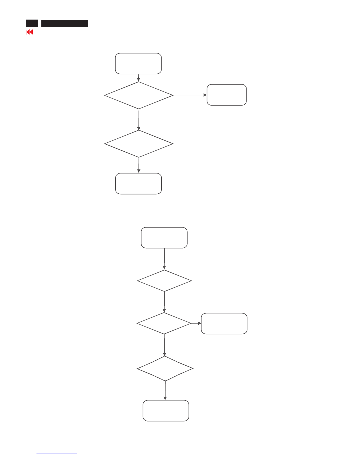
Repair Flow Chart-2
170X5 LCD
20
Go to cover page
Bad brightness
No
Check
Inverter panel output
625~765Vrms
Bad Inverter
panel
Yes
Check fluorescent
lamp
No
Check LCD panel
Bad image
Check
Video, fh/fv
signals
Yes
Check main panel
Yes
Check components
cold soldering
No
Check
all connectors &
LVDS cable
No
Check LCD panel
Repair Flow Chart-3
170X5 LCD
All units that are returned for service or repair must pass the
original manufactures safety tests. Safety testing requires both
and testing.Hipot Ground Continuity
HI-POT TEST INSTRUCTION
1.Application requirements
Test method
1.1 All mains operated products must pass the Hi-Pot test as
described in this instruction.
1.2 This test must be performed again after the covers have
been refitted following the repair, inspection or modification
of the product.
2.1 Connecting conditions
2.1.1 The test specified must be applied between the parallel-
blade plug of the mainscord and all accessible metal
parts of the product.
2.1.2 Before carrying out the test, reliable conductive
connections must be ensured and thereafter be
maintained throughout the test period.
2.1.3 The mains switch(es) must be in the "ON" position.
2.2 Test Requirements
All products should be HiPot and Ground Continuity tested as
follows:
Test 2820VDC 1700VDC Test current:
voltage (2000VAC) (1200VAC) 25A,AC
Test time:
Test time 3 seconds 1 second 3 seconds(min.)
(min.) Resistance
required:
Trip set at 100 uA 5 mA <=0.09+Rohm,
current for Max. R is the
(Tester) limitation; set resistance of
at 0.1 uA for the mains cord.
Min. Limitation
Ramp set at 2
time seconds
(Tester)
2.
Condition HiPot Test for HiPot Test for Ground Continuity
products where products where Test requirement
the mains input the mains input is
range is Full 110V AC(USA
range(or 220V type)
AC)
2.2.1 The minimum test duration for Quality Control Inspector
must be 1 minute.
2.2.2 The test voltage must be maintained within the specified
voltage + 5%.
2.2.3 There must be no breakdown during the test.
2.2.4 The grounding blade or pin of mains plug must be
conducted with accessible metal parts.
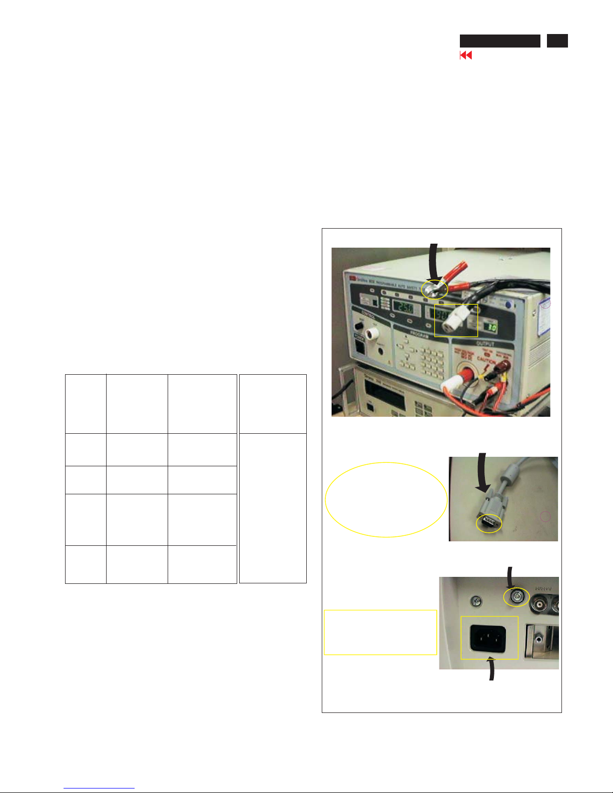
3. Equipments and Connection
3.1. Equipments
For example :
- ChenHwa 9032 PROGRAMMABLE AUTO SAFETY
TESTER
- ChenHwa 510B Digital Grounding Continuity Tester
- ChenHwa 901 (AC Hi-pot test), 902 (AC, DC Hi-pot test)
Withstanding Tester
3.2. Connection
4. Recording
Hipot and Ground Continuity testing records have to be kept
for a period of 10 years.
* Turn on the power switch of monitor before Hipot and
Ground Continuity testing.
Connect the "video cable"
or "grounding screw"
to the CLIP on your tester.
Video cable
(Rear view of monitor)
Connect the power cord
to the monitor.
Grounding screw
Power outlet
(ChenHwa 9032 tester)
Clip
Clip
Safety Test Requirement
Go to cover page
21
170X5 LCD
0. Warning
All ICs and many other semi-conductors are susceptible to
electrostatic discharges (ESD). Careless handling during
repair can reduce life drastically. When repairing, make sure
that you are connected with the same potential as the mass
of the unit via a wrist wrap with resistance. Keep components
and tools also at the same potential !
1. Servicing of SMDs (Surface Mounted Devices)
1.1 General cautions on handling and storage
- Oxidation on the terminals of SMDs results in poor soldering.
Do not handle SMDs with bare hands.
- Avoid using storage places that are sensitive to oxidation
such as places with sulphur or chlorine gas, direct sunlight,
high temperatures or a high degree of humidity. The
capacitance or resistance value of the SMDs may be
affected by this.
- Rough handling of circuit boards containing SMDs may
cause damage to the components as well as the circuit
boards. Circuit boards containing SMDs should never be
bent or flexed. Different circuit board materials expand and
contract at different rates when heated or cooled and the
components and/or solder connections may be damaged
due to the stress. Never rub or scrape chip components as
this may cause the value of the component to change.
Similarly, do not slide the circuit board across any surface.
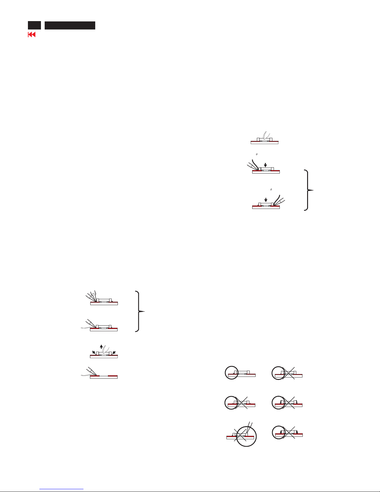
1.2 Removal of SMDs
- Heat the solder (for 2-3 seconds) at each terminal of the
chip. By means of litz wire and a slight horizontal force,
small components can be removed with the soldering iron.
They can also be removed with a solder sucker (see Fig.
1A)
- While holding the SMD with a pair of tweezers, take it off
gently using the soldering iron's heat applied to each
terminal (see Fig. 1 B).
- Remove the excess solder on the solder lands by means of
litz wire or a solder sucker (see Fig. 1C).
1.3 Caution on removal
- When handling the soldering.iron. use suit able pressure and
be careful.
- When removing the chip, do not use undue force with the
pair of tweez ers.
-Thesolderingirontobeused(approx.30W)should
Fig. 1 DISMOUNTING
SOLDERING
IRON
E.g. WELLER
SOLDER TIP PT-H7
VACUUM PISTON
4822 395 10159
SOLDER WICK
4822 321 40042
E.g. A PAIR OF TWEEZERS
HEATING
SOLDERING
IRON
SOLDER WICK
C
B
A
SOLDERING
IRON
HEATING
Fig. 2 MONUTING
E.g. A PAIR OF TWEEZERS
SOLDER
0.5-0.8 mm
PRESURE
SOLDERING
IRON
SOLDERING TIME
< 3 sec/side
B
A
SOLDER
0.5-0.8 mm
PRESURE
SOLDERING
IRON
Fig. 3 Examples
RIGHT
SOLDERING
IRON
Preferably be equipped with a thermal control
(soldering temperature:225 degree V to 250 degree C.
-The chip, once removed, must never be reused.
-Locate the SMD on the solder lands by means of tweezers
and solder the component on one side. Ensure that the
component is positioned correctly on the solder lands (see Fig. 2A)
-Next complete the soldering of the terminals of the component.
(See Fig. 2B)
1.4 Attachment of SMDs
2. Caution when attaching SMDs
- When soldering the SMDs terminals, do not touch them
directly with the soldering iron. The soldering should be
directly with the soldering iron. The soldering should be
done as quickly as possible, care must be taken to avoid
damage to the terminals of the SMDs themselves.
- Keep the SMD's body in contact with the printed board
when soldering.
- The soldering iron to be used (approx. 30W) should
preferably be equipped with a thermal control (soldering
temperature:225 degree C to 250 degree C).
- Soldering should not be done outside the solder land.
- Soldering flux (of rosin) may be used, but should not
be acidic.
- After soldering, let the SMDs cool down gradually at room
temperature.
- The quantity of solder must be proportional to the size of
the solder land. If the quantity is too great, the SMD might
crack or the solder lands might be torn loose from the
printed board (See Fig. 3).
Repair Tips
22
Go to cover page
170X5 LCD
23
170X5 LCD
Go to cover page
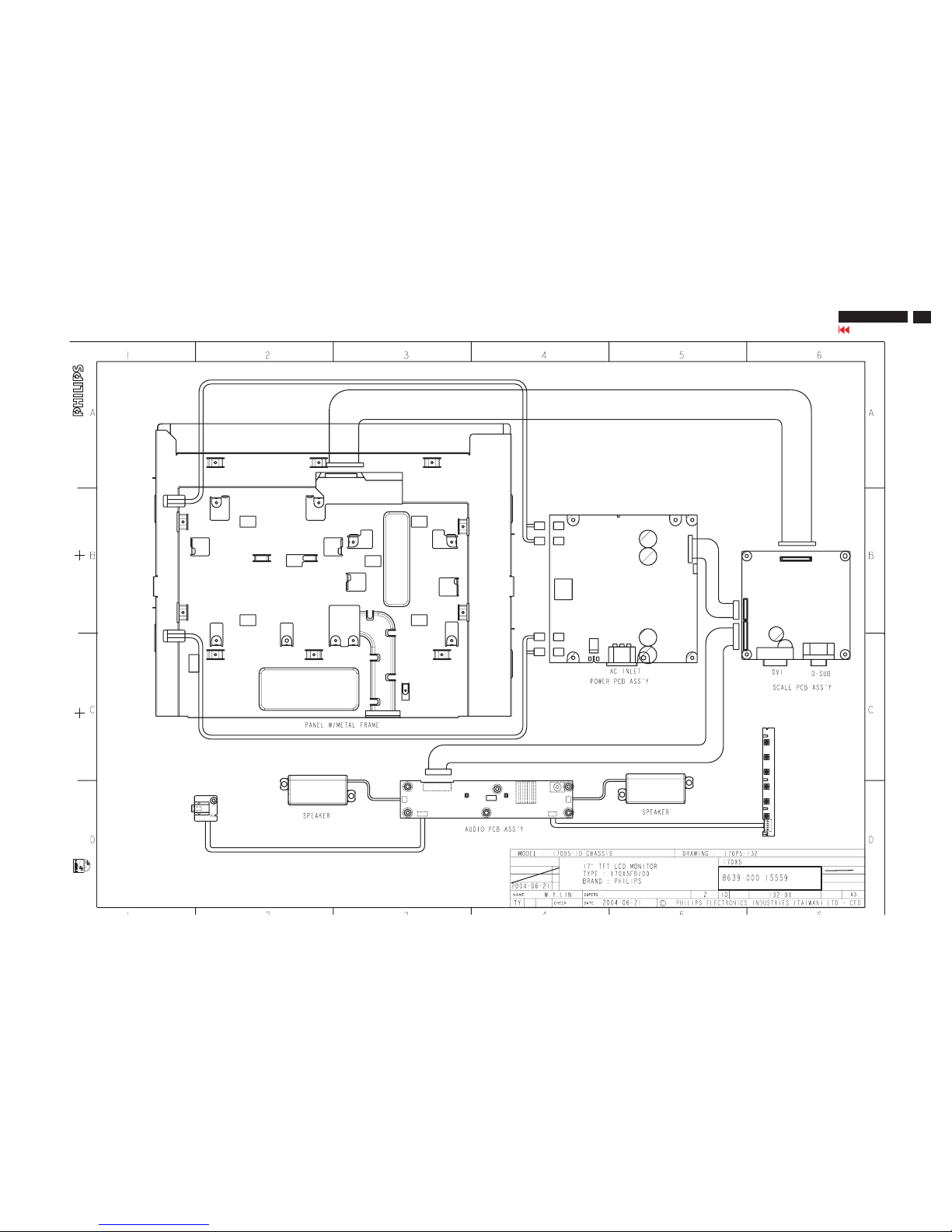
Wiring Diagram
24
170X5 LCD
Go to cover page
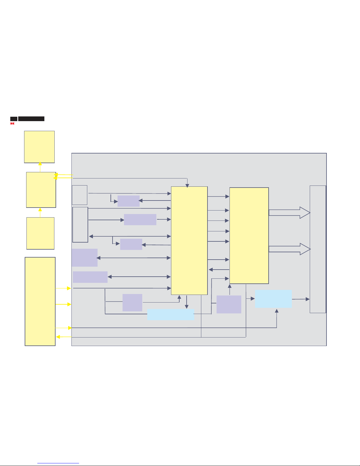
Function Block Diagram
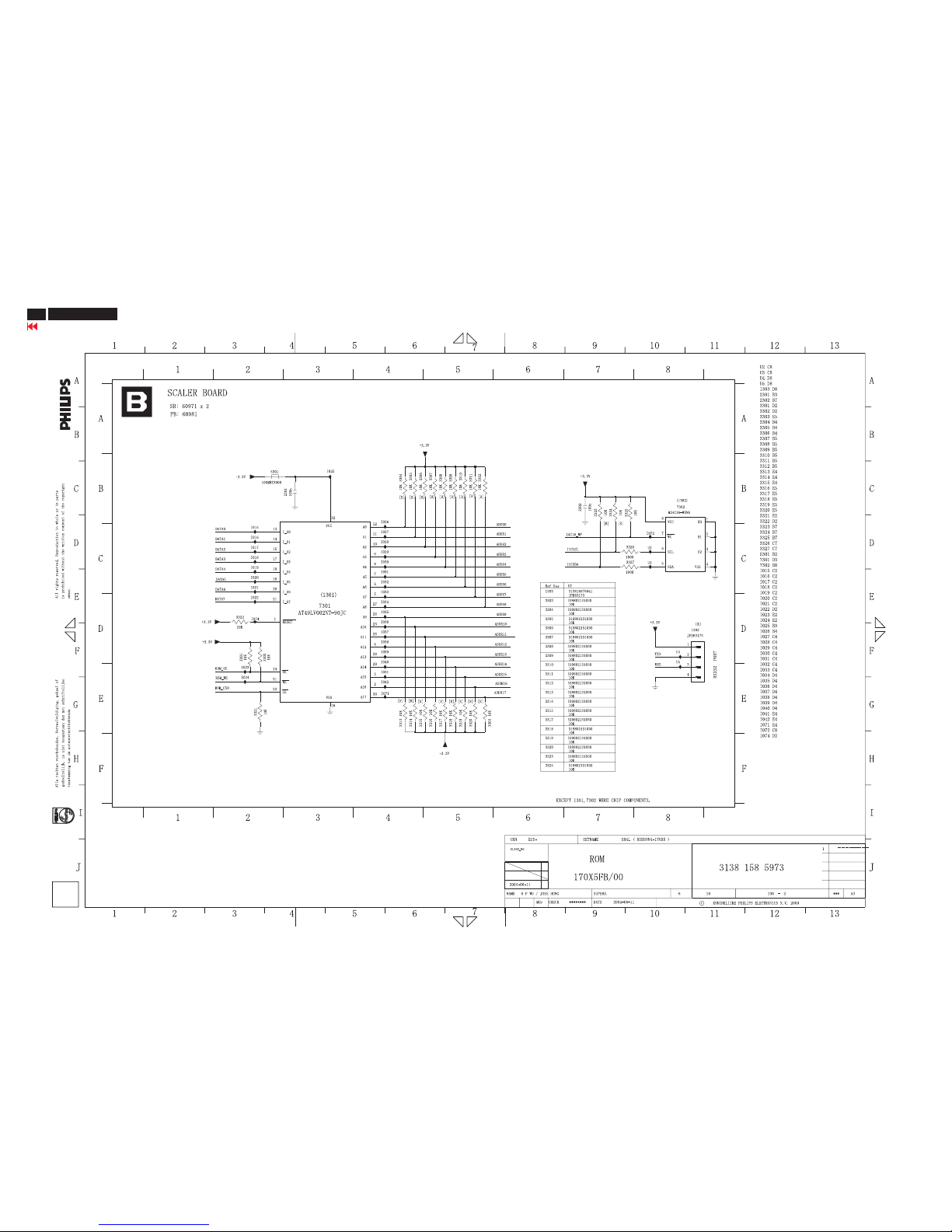
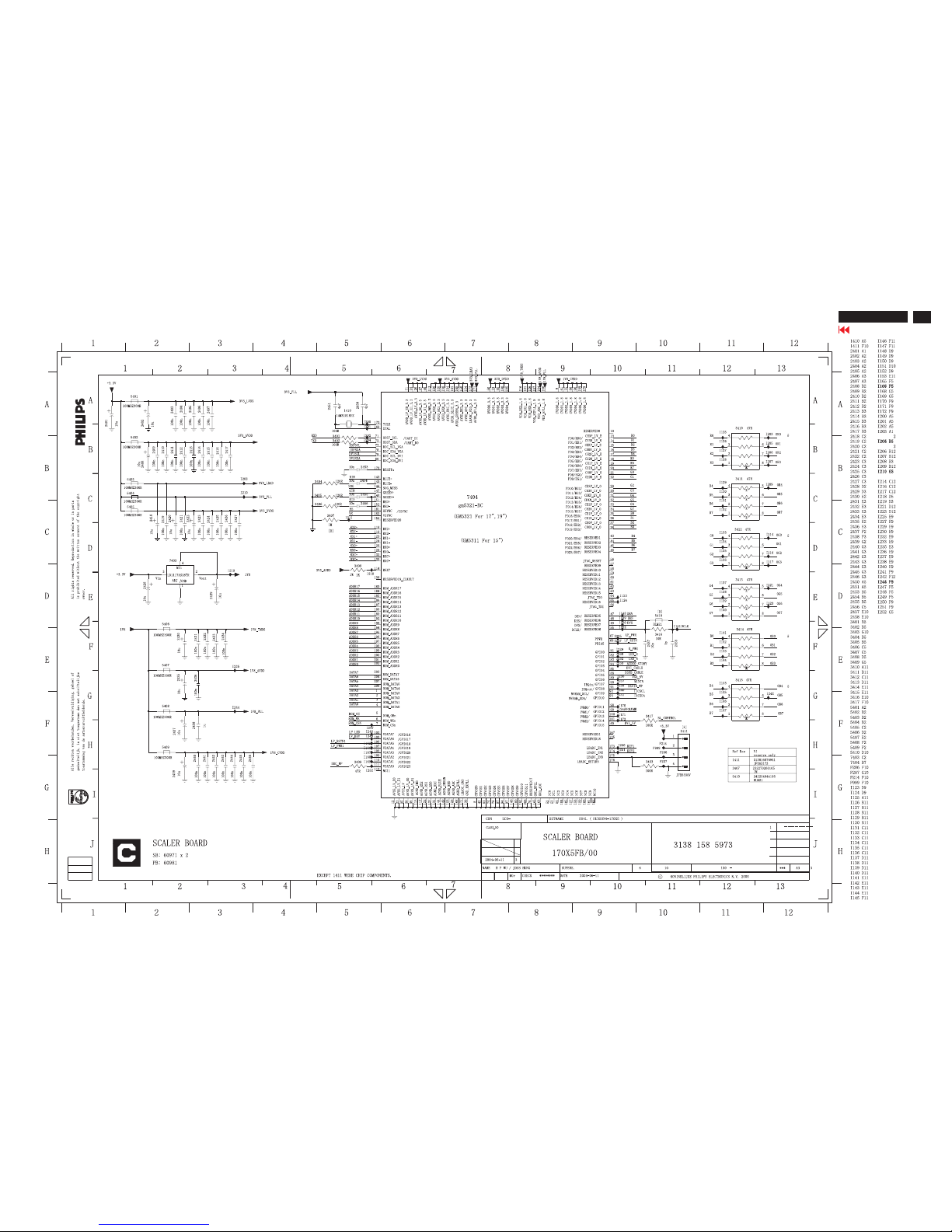
Scaler
gm5321BC
R/G/B
ADDR0/17, Data0/7
Bank, OM_OE/WE/CSN
Flash
ROM
D-SUB
Schmitt
HS/VS
DDC
EEPROM
IIC
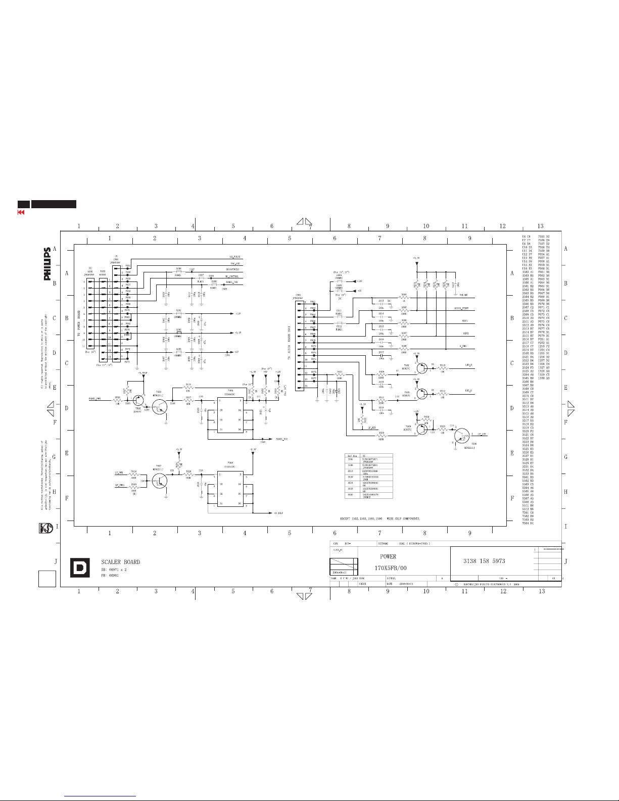
AC to DC
Inverter
Board
BL_EN / Brightness
Panel PWR
MOS
5V
Audio
Control
Board
3.3V
5V
1.8V
Reg.
TXE/0/1/2/3/C
30 pin connector
TXO/0/1/2/3/C
ISPSCL,SDA
OSD Key
LEDR,G/LF_LED/Volume/PWR/OSD Key
DVI
R+-/G+-/B+-/CLK+-
LF IC
Pacific
1SB
2.5V/1.5V
Reg.
R/G/B
DHS
DVS
DEN
DCLK
LF_PWR MOS
DDC
12V
12V
LF_RSTN
MINTN
DDC_WP
DDC_WP
BL_EN
Brightness
OSD
Key
Board
Headphone
Board
25
Go to cover page
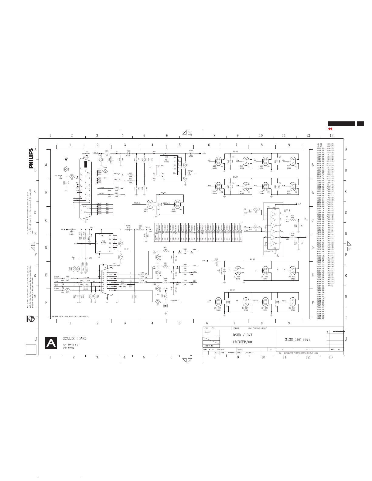
Scaler Schematic Diagram-1
170X5 LCD
26
Go to cover page
Scaler Schematic Diagram-2
170X5 LCD
27
Go to cover page
Scaler Schematic Diagram-3
170X5 LCD
28
Go to cover page
Scaler Schematic Diagram-4
170X5 LCD
 Loading...