

Philips HUDSON IV 150C5 Service Manual
15"XGATFTLCDMonitor
http://jdwxzlw.com/?fromuser=华盛维修
家电维修资料网,免费下载各种维修资料
Service
Service
Service
HUDSON IV 150C5
Model: 150C5BS/00
Horizontal Frequencies
30 - 61KHz
TABLE OF CONTENTS
Description Page
Important Safety Notice ---------------------------------- 2
Technical Data ------------------------------------------3~4
Philips Pixel Defect Policy--------------------------------5
Troubleshooting--------------------------------------------6
Installation -----------------------------------------------7~9
On Screen Display---------------------------------------10
Electrical Instructions------------------------------------11
Safety Test Requirement--------------------------------12
Mechanical Instructions----------------------------13
Factory Mode &Aging Mode---------------------------15
Warning Message----------------------------------------16
Repair Tips------------------------------------------------17
Repair Flow Chart-----------------------------------18
Wiring Diagram-------------------------------------------21
ANYPERSON ATTEMPTING TO SERVICETHISCHASSISMUSTFAMILIARIZE HIMSELF WITH THE CHASSIS
AND BE AWARE OF THENECESSARYSAFETYPRECAUTIONS TO BE USED WHEN SERVICING ELECTRONIC
EQUIPMENT CONTAINING HIGH VOLTAGES.
~14
~20
SAFETY NOTICE
Description Page
«
Function BlockDiagram
Scaler Schematic Diagram-----------------------23~26
Scaler Board C.B.A.--------------------------------27~28
Control Schematic Diagram & C.B.A.---------------29
Power Schematic Diagram------------------------30~31
Exploded View
Recommended Parts List -----------------------------35
Failure Mode Of Panel----------------------------------36
General Product Specification-------------------37~58
DDC Instructions------------------------------------59~63
DDC Data-------------------------------------------------64
-------------------------------------------32
--------------------------------22
34Spare Parts List------------------------------------33~
-----------------------65Firmware Update For CPU
~67
CAUTION:USEASEPARATE ISOLATION TRANSFORMER FOR THISUNIT WHEN SERVICING.
REFER TO BACK COVER FOR IMPORTANT SAFETY GUIDELINES
Published by BCU Monitors Printed in Suzhou Copyright reserved Subject to modification H July. 9 2004
GBGB
3138 10610406
2
http://jdwxzlw.com/?fromuser=华盛维修
家电维修资料网,免费下载各种维修资料
150C5 LCD
Go to cover page
Important Safety Notice
Proper service and repair is important to the safe, reliable
operation of all Philips Consumer Electronics Company**
Equipment. The service procedures recommended by
Philips and described in this service manual are effective
methodsofperformingserviceoperations.Someofthese
service operations require the use of tools specially designed
forthepurpose.Thespecialtoolsshouldbeusedwhenand
as recommended.
Itisimportanttonotethatthismanualcontainsvarious
CAUTIONSandNOTICESwhichshouldbecarefullyreadin
order to minimize the risk of personal injury to service
personnel. The possibility exists that improper service
methods may damage the equipment. It is also important to
understand that these CAUTIONS and NOTICES ARE NOT
EXHAUSTIVE. Philips could not possibly know, evaluate and
advisetheservicetradeofallconceivablewaysinwhich
service might be done or of the possible hazardous
consequences of each way. Consequently, Philips has not
undertaken any such broad evaluation. Accordingly, a
servicer who uses a service procedure or tool which is not
recommended by Philips must first satisfy himself thoroughly
thatneitherhissafetynorthesafeoperationofthe
equipment will be jeopardized by the service method
selected.
* *Hereafter throughout this manual, Philips Consumer
Electronics Company will be referred to as Philips.
WARNING
Critical components having special safety characteristics are
identifiedwitha bytheRef.No.inthepartslistand
enclosed within a broken line*
(where several critical components are grouped in one area)
along with the safety symbol on the schematics or
exploded views.
Use of substitute replacement parts which do not have the
same specified safety characteristics may create shock, fire,
or other hazards.
!
!
FOR PRODUCTS CONTAINING LASER :
DANGER-
CAUTION-
CAUTION-
TO ENSURE THE CONTINUED RELIABILITY OF THIS
PRODUCT, USE ONLY ORIGINAL MANUFACTURER'S REPLACEMENT
PARTS, WHICH ARE LISTED WITH THEIR
PARTNUMBERSINTHEPARTSLISTSECTIONOFTHISSERVICE
MANUAL.
Invisible laser radiation when open.
AVOIDDIRECTEXPOSURETOBEAM.
Use of controls or adjustments or
performance of procedures other than
those specified herein may result in
hazardous radiation exposure.
The use of optical instruments with this
product will increase eye hazard.
Take care during handling the LCD module with backlight unit
- Must mount the module using mounting holes arranged in four
corners.
-Donotpressonthepanel,edgeoftheframestronglyorelectric
shock as this will result in damage to the screen.
- Do not scratch or press on the panel with any sharp objects, such
as pencil or pen as this may result in damage to the panel.
- Protect the module from the ESD as it may damage the electronic
circuit (C-MOS).
- Make certain that treatment person s body are grounded through
wrist band.
-Donotleavethemoduleinhightemperatureandinareasofhigh
humidityforalongtime.
-Avoidcontactwithwaterasitmayashortcircuitwithinthe
module.
-Ifthesurfaceofpanelbecomedirty,pleasewipeitoffwithasoft
material. (Cleaning with a dirty or rough cloth may damage the
panel.)
Under no circumstances should the original design be
modified or altered without written permission from Philips.
Philips assumes no liability, express or implied, arising out of
any unauthorized modification of design.
Servicer assumes all liability.
* Broken Line

Technical Data
http://jdwxzlw.com/?fromuser=华盛维修
家电维修资料网,免费下载各种维修资料
150C5 LCD
Go to cover page
3
Product Features
Outstanding front of screen performance
Fast response time capable of handling fast moving pictures
sRGB ensures color matching between display and printouts
XGA 1024 x 768 resolution for sharper display
Design that complements any interior
Elegant, sleek design complements your home d cor
Compact and slim design saves space and fits anywhere
Best value for money
TCO guarantees the highest safety and ergonomics standards
The lower power consumption than industry average
Great convenience
Embedded power supply eliminates external power adaptors
Auto adjustment for perfect picture display with one touch
Easily adjust display settings with Philips SmartControl
Cable clip manages cables for a tidy work space
Detachable base for easy moving and storage
Screen tilts for comfortable viewing from any angle
Technical Specifications*
LCD PANEL
Type TFT LCD
Screen size 15" visual (38cm)
Peak contrast angle 6 o'clock
White Chromaticity x: 0.313y:0.329 (at 6500 K)
Viewing Angle (C/R>=10) Lower 55 (typ.)
Response time 16 ms (typ.)
SRGB
sRGB is a standard
different devices (e.g. digital cameras, monitors, printers, scanners, etc.)
Using a standard unified color space, sRGB will help represent pictures
taken by an sRGBcompatible device correctly on your sRGB enabled
Philips monitors. In that way, the colors are calibrated and you can rely
on the correctness of the colors shown on your screen.
Important with the use of sRGB is that the brightness and contrast of
your monitor is fixed to a predefined setting as well as the color gamut.
Therefore it is important to select the sRGB setting in the monitor's OSD.
To do so, open the OSD by pressing the OK button on the front of your
monitor. Use the down button to go to Adjust Color and press OK again.
Then move the down button to go to sRGB and press OK again.
for ensuring correct exchange of colors between
x: 0.283y:0.297 (at 9300 K)
x: 0.313y:0.329 (at sRGB)
Upper 45 (typ.)
Left 65 (typ.)
Right 65 (typ.)
O
O
O
O
O
O
Pixel Pitch 0.297 x 0.297 mm
1024 x 768 pixels
LCD Panel type
Ef fective viewing area 304.1 x228.1 mm
Display Colors 16M colors
SCANNING
Vertical refresh rate 56 Hz-76 Hz
Horizontal Frequency 30 kHz-61 kHz
VIDEO
V ideo dot rate 80 Mhz
Input impedance
- Video 75 ohm
- Sync 2K ohm
Input signal levels 700m Vpp
Sync input signal
Sync polarities Positive and negative
Input Frequency
R.G.B. vertical stripe
Anti-glare polarizer, hard coated
Separate sync
Composite sync
Sync
on green
XGA Hsync 48- 61 kHz,
Vsync 60 - 76 Hz (N.I.)
SVGA Hsync 35- 50 kHz,
Vsync 56 - 75 Hz (N.I.)
VGA Hsync 31-38 kHz,
Vsync 60 - 76 Hz (N.I.)
After this, please do not change the brightness or contrast setting of your
monitor. If you change either of these, the monitor will exit the sRGB
mode and go to a color temperature setting of 6500K.
For more information on sRGB, please visit: www.srgb.com
Resolution & Preset Modes
Maximum 1024 X 768 at 75Hz
Recommended 1024 X 768 at 60 Hz
15 user definable modes
14 factory preset modes:
H. Freq (kHz) Resolution V. freq (Hz)
31.469 640*350 70.086
31.469 720*400 70.087
31.469 640*480 59.940
35.000 640*480 67.000
37.861 640*480 72.809
37.500 640*480 75.000
35.156 800*600 56.250
37.879 800*600 60.317
48.077 800*600 72.188
46.875 800*600 75.000
V ideo interface Analog (D-Sub)
Optical characteristics
contrast ratio 400:1 (typ.)
Brightness 250 cd/m (typ.)
2
49.700
48.363 1024*768 60.004
56.476 1024*768 70.069
60.023 1024*768 75.029
832*62475.000
4
http://jdwxzlw.com/?fromuser=华盛维修
家电维修资料网,免费下载各种维修资料
150C5 LCD
Go to cover page
Technical Data
Automatic Power Saving
If you have VESA DPMS compliance display card or software installed in
your PC, the monitor can automatically reduce its power consumption
when not in use. If an input from a keyboard, mouse or other input device
is detected, the monitor will 'wake up' automatically. The following table
shows the power consumption and signaling of this automatic power
saving feature:
Power Management Definition
VESA Mode Video H-sync V-sync Power Used LED color
ON Active Yes Yes < 20 W Green
OFF Blanked No No <1W Amber
This monitor is ENERGY STAR compliant. As an ENERGY STAR
Partner, PHILIPS has determined that this product meets the ENERGY
R
STAR guidelines for energy efficiency.
R
R
Physical Specification
Dimension (WXHXD)* 360 x349 x173.5 mm (incl. Pedestal)
Weight 2.97 Kg
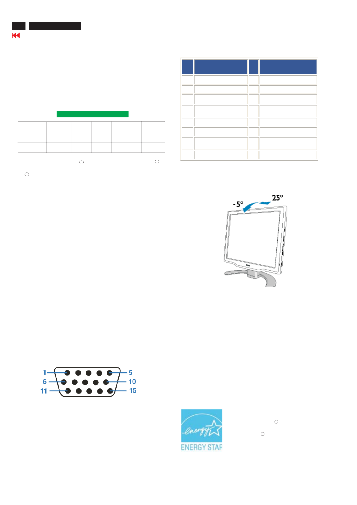
O
Tilt -5 --25
Power Supply 100 ---240VAC, 50/60 Hz
O
Pin
Assignment
No.
1 Red v ideo input 9 +5V
2 Green video input/SOG 10 Logic ground
3 Blue video input 11 Ground
4 Sense (GND) 12 Serial data line (SDA)
5 Hot Plug Detect 13 H. Sync / H+V
6 Red v ideo ground 14 V. S y n c (VC L K for DDC)
7 Green video ground 15 Data clock line (SCL)
8 Blue video ground
Pin
No.
Assignment
Physical Function
Tilt
Power consumption 18 W* (typ.)
O
Temperature 5 Cto40 C (operating)
-20 Cto60 C (storage)
O
O
O
Relative humidity 20% to 80%
System MTBF 50K hours (excluding CCFL 40K hours)
*This data is subject to change without notice.
*Resolution 1024 X 768, standard size, brightness max., Contrast 50%,
full white pattern.
Pin Assignment
The 15-pin D-sub connector(male) of the signal cable(IBM systmes):
Energy Star Declaration
This monitor is equipped with a function for saving energy which
supports the VESA Display Power Management Signaling (DPMS)
standard. This means that the monitor must be connected to a
computer which supports VESA DPMS to fulfill the requirements
in the NUTEK specification 803299/94. Time settings are adjusted
from the system unit by software
.
NUTEK VESA State LED Indicator Power Consumption
Normal operation ON Green < 20 W
Power Saving
Alternative 2
One step
OFF Amber <1W
As an ENERGY STAR Partner, PHILIPS has
determined that this product meets the
ENERGY STAR guidelines for energy
efficiency.
R
R
Philips Pixel Defect Policy
http://jdwxzlw.com/?fromuser=华盛维修
家电维修资料网,免费下载各种维修资料
150C5 LCD
Go to cover page
5
Philips' Flat Panel Monitors Pixel Defect Policy
Philips strives to deliver the highest quality products. We
use some of the industry's most advanced manufacturing
processes and practice stringent quality control. However,
pixel or sub pixel defects on the TFT LCD panels used in
flat panel monitors are sometimes unavoidable. No
manufacturer can guarantee that all panels will be free
from pixel defects, but Philips guarantees that any monitor
with an unacceptable number of defects will be repaired or
replaced under warranty. This notice explains the different
types of pixel defects and defines acceptable defect levels
for each type. In order to qualify for repair or replacement
under warranty, the number of pixel defects on a TFT LCD
panel must exceed these acceptable levels. For example,
no more than 0 .0004% of the sub pixels on a 15" XGA
monitor may be defective. Furthermore, Philips sets even
higher quality standards for certain types or combinations
of pixel defects that are more noticeable than others. This
policy is valid worldwide.
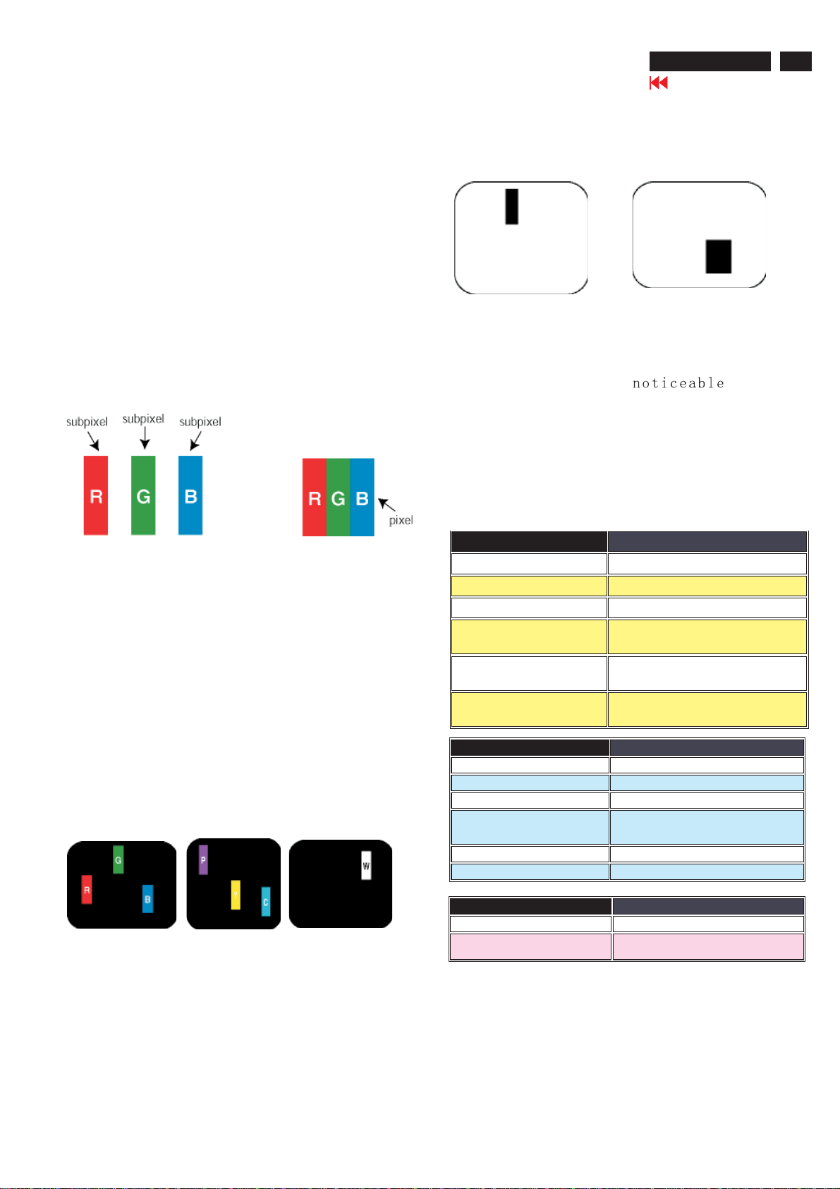
Black Dot Defects Black dot defects appear as pixels or sub
pixels that are always dark or 'off'. These are the types of black
dot defects:
One dark sub pixel Two or three adjacent dark sub pixels
Proximity of Pixel D efects
Because pixel and sub pixels defects of the same type that are
near to one another may be more , Philips also
specifies tolerances for the proximity of pixel defects.
Pixel Defect Tolerances
In order to qualify for repair or replacement due to pixel defects
during the warranty period, a TFT LCD panel in a Philips flat panel
monitor must have pixel or sub pixel defects exceeding the
tolerances listed in the following tables.
Pixels and Sub pixels
A pixel, or picture element, is composed of three sub pixels
in the primary colors of red, green and blue. Many pixels
together form an image. When all sub pixels of a pixel are lit,
the three colored sub pixels together appear as a single
white pixel. When all are dark, the three colored sub pixels
together appear as a single black pixel. Other combinations
of lit and dark sub pixels appear as single pixels of other
colors.
Types of Pixel Defects
Pixel and sub pixel defects appear on the screen in different
ways. There are two categories of pixel defects and several
types of sub pixel defects within each category. Bright dot
defects appear as pixels or sub pixels that are always lit or
'on'. These are the types of bright dot defects:
One lit red,
green or
blue sub pixel
Two adjacent lit
sub pixels:
- Red + Blue = Purple
- Red + Green = Yellow
- Green + Blue = Cyan
(Light Blue)
Three adjacent lit
sub pixels
(one white pixel)
BRIGHT DOT DEFECTS ACCEPTABLE LEVEL
MODEL
1 lit subpixel 4 or fewer
2 adjacent lit subpixels 2 or fewer
3 adjacent lit subpixels (one white
pixel)
Distance between two bright dot
defects*
Total bright dot defects of all types 4 or fewer
BLACK DOT DEFECTS ACCEPTABLE LEVEL
MODEL 150C5
1 dark subpixel 4 or fewer
2 adjacent dark subpixels 2 or fewer
3 adjacent dark subpixels 1 or fewer
Distance between two black dot defects* 15 mm or more
Total black dot defects of all types 4 or fewer
TOTAL DOT DEFECTS ACCEPTABLE LEVEL
MODEL 150C5
Total bright or black dot defects of all
types
150C5
0
15 mm or more
5 or fewer
Note:
* 1 or 2 adjacent sub pixel defects =1dot defect
All Philips monitors are ISO13406-2 Compliant
6
http://jdwxzlw.com/?fromuser=华盛维修
家电维修资料网,免费下载各种维修资料
150C5 LCD
Go to cover page
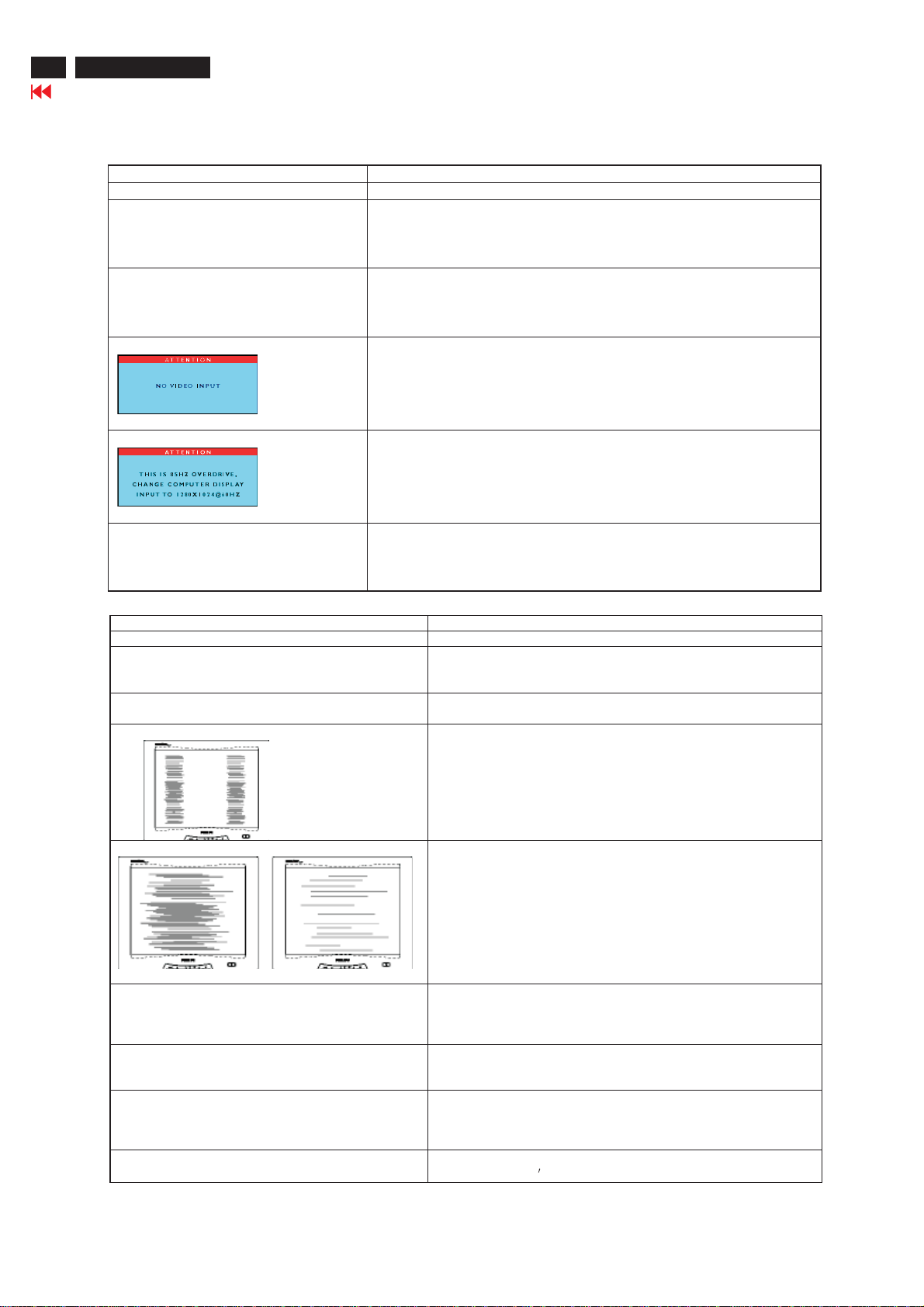
Common Problem s
Having this problem? Check these items
No Picture
(power LED not lit)
No Picture
(Power LED is amber or yellow)
Screen says
Troubleshooting
This page deals with problems that can be corrected by the user.
· Make sure the power cord is plugged into the power outlet
and into the back of the monitor.
· First, ensure that the power button on the front of the monitor is in
the OFF position, then press it to the ON position
· Make sure the computer is turned on.
· Make sure the signal cable is properly connected to your computer.
· Check to see if the monitor cable has bent pins.
· The Energy Saving feature may be activated
· Make sure the monitor cable properly connected to your computer.
(Also refer to the Quick Set-Up Guide).
· Check to see if the monitor cable has bent pins,
· Make sure the computer is turned on.
Screen says
AUTO button not working properly
Image Problems
Having this problem? Check these items
Display position is incorrect
Image vibrates on the screen
Vertical flicker appears
Horizontal flicker appears
· Make sure the vertical sync of input signal is within the range of
56--75Hz.
· Change the refresh rate to 56--75Hz within 10 minutes.
· Re-power on monitor to start over again if you failed to change the
refresh rate within 10 minutes.
· The Auto Function is designed for use on standard Macintosh or
IBM-compatible PCs running Microsoft Windows.
· It may not work properly if using nonstandard PC or video card.
· Press the AUTO button
· Adjust the image position using the Horizontal Position
and/or Vertical Position in OSD Main Controls.
· Check that the signal cable is properly connected to the
graphics board or PC.
· Press the AUTO button
· Eliminate the vertical bars using the Clock Adjustment of
VIDEO NOISE in OSD Main Controls.
· Press the AUTO button
· Eliminate the horizontal bars using the Phase
Adjustment of VIDEO NOISE in OSD Main Controls.
The screen is too bright or too dark
An after-image appears
An after-image remains after the power has
been turned off.
Green, red, blue, and white dots remains
· Adjust the contrast and brightness on OSD Main Controls. (The
backlight of the LCD monitor has a fixed life span. When the
screen becomes dark or begins to flicker, please contact your
dealer).
· If an image remains on the screen for an extended period of time,
it may be imprinted in the screen and leave an after-image. This
usually disappears after a few hours.
· This is characteristic of liquid crystal and is not caused by a
malfunction or deterioration of the liquid crystal. The after-image
will disappear after a period of time.
· The remaining dots are normal characteristic of the liquid crystal
used in today
s technology.
Installations
http://jdwxzlw.com/?fromuser=华盛维修
家电维修资料网,免费下载各种维修资料
150C5 LCD
Go to cover page
7
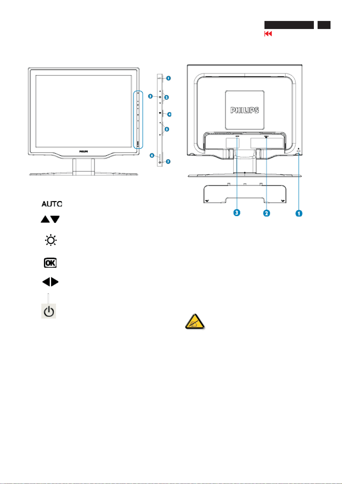
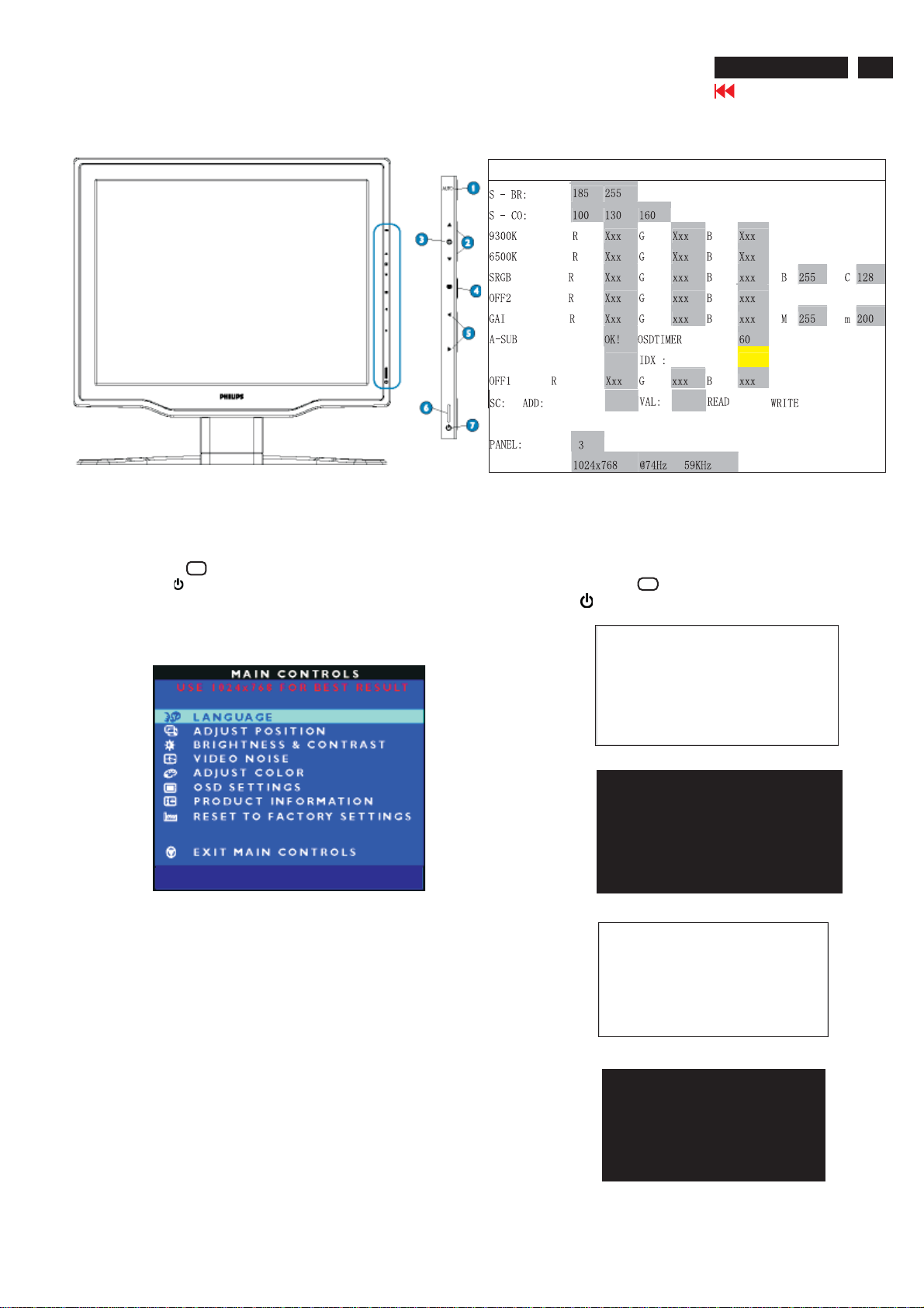
Front view product description
1 Automatically adjust the horizontal position,
vertical position, phase and clock setting.
2 UP and DOWN buttons are used when
adjusting the OSD of your monitor.
3 BRIGHTNESS hotkey. When the UP and
DOWN arrow buttons are pressed, the
adjustment controls for the BRIGHTNESS will
show up.
Back view product description
1Kensington anti-thief lock
2 VGA input
3 AC power input
4 OK button which when pressed will take you to
the OSD controls.
5 LEFT and RIGHT buttons, like the UP and
DOWN buttons, are also used in adjusting the
OSD of your monitor.
6 Power LED
7 POWER button switches your monitor on.
Optimizing Performance
For best performance, ensure that your display settings are set at
1024x768, 60Hz.
You can check the current display settings by pressing
Note:
the 'OK' button once. Go into the Product Information.
The current display mode is shown on the item called
RESOLUTION.
You can also install the , a
program for getting the best performance out of your monitor. This is
included on this CD. Step-by-step instructions are provided to guide
you through the installtion process. Click on the link to know more about
this program.
Flat Panel Adjust (FP Adjust) program
8
http://jdwxzlw.com/?fromuser=华盛维修
家电维修资料网,免费下载各种维修资料
150C5 LCD
Go to cover page
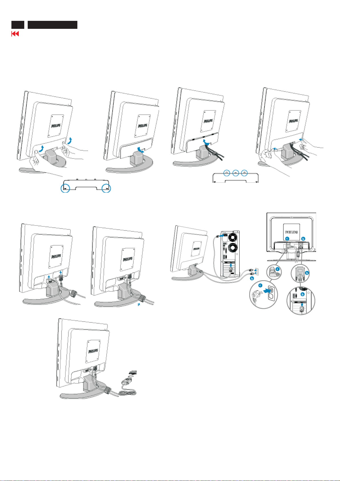
Installations
Connecting to Your PC
1)
2)
3)
4)
Connect to PC
4)
(a)
Turn off your computer and unplug its power cable.
(b)
Connect the monitor signal cable to the video connector on
the back of your computer.
(c)
Plug the power cord of your computer and your monitor into a
nearby outlet.
(d)
Turn on your computer and monitor. If the monitor displays an
image, installation is complete.
Note: If you use an Apple Macintosh, you need to connect the
special Mac adapter to one end of the monitor signal cable.
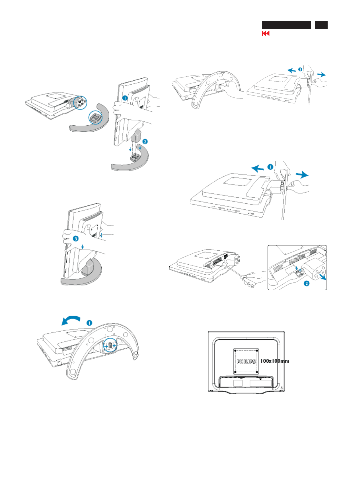
Attaching & Detaching and Removing the base
http://jdwxzlw.com/?fromuser=华盛维修
家电维修资料网,免费下载各种维修资料
To attach the base:
1)
Hold the monitor body with both hands.
2)
Align four-pronged base attachment unit on the bottom of
the screen with the four socket holes on the base.
Installations
2)1)Press the release latches on the bottom of the base
together and gently remove the attachment unit from the
base.
To remove the base for VESA standard mounting applications
150C5 LCD
Go to cover page
9
3)
Firmly fix screen into the base plate.
To detach the base:
1) Place the monitor face down a smooth surface taking care
to avoid scratching or damaging the screen.
Detach the screen from the base.
2) Remove the screws and then detach the base attachment unit
from the LCD monitor.
Note: This monitor is designed to work with a 100mm x 100mm
VESA-compliant mounting interface.
10
http://jdwxzlw.com/?fromuser=华盛维修
家电维修资料网,免费下载各种维修资料
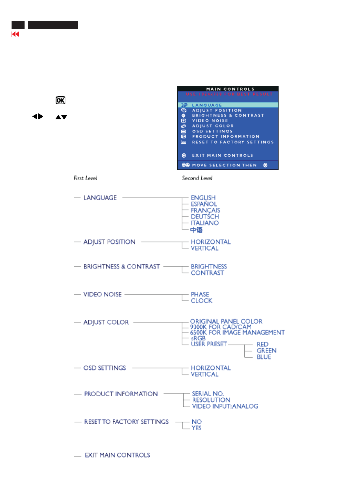
What is the On-Screen Display?
This is a feature in all Philips LCD monitors. It allows an end user to adjust screen performance of the monitors directly through an on-screen
instruction window. The user interface provides user friendliness and ease-of-use when operating the monitor.
Basic and simple instruction on the control keys.
When you press the button on the side control of your monitor,
the On-Screen Display (OSD) Main Controls window will pop up and
you can then start making adjustments to your monitor's various features.
Use the or the keys to make your adjustments.
The OSD Tree
Below is an overall view of the structure of the On-Screen Display. You
can use this as a reference when you want to work your way around
the different adjustments later on.
150C5 LCD
Go to cover page
On-Screen Display
Description of the On Screen Display
Electrical Instructions
http://jdwxzlw.com/?fromuser=华盛维修
家电维修资料网,免费下载各种维修资料
150C5 LCD
Go to cover page
11
1. Gen eral points
1.1 During the test and measuring, supply a distortion free AC
1.2 All measurements mentioned hereafter are carried out at a
1.3 All voltages are to be measured or applied with respect to
1.4 The test has to be done on a complete set including LCD
1.5 All values mentioned in this test instruction are only applicable
1.6 The letters symbols (B) and (S) placed behind the test
1.7 The white balance (color temperature), has to be tested in
1.8 Repetitive power on/off cycle are allowed except it should
mains Voltage to the apparatus via an isolated transformer
with low internal resistance.
Normal mains voltage (90 - 132 VAC for USA version,
195 -264 VAC for EUROPEAN version, or 90 - 264 VAC
for the model with full range power supply, unless otherwise
stated.)
ground, unless otherwise stated.
Note: don
panel after 30 minutes warm-up at least in a room with
temperature of 25 +/- 5 degree C.
of a well aligned apparatus, with correct signal.
instruction denotes(B): carried out 100% inspection at
assembly line (S): carried out test by sampling
subdued lighted room.
be avoided within 6 sec.
t use heat-sink as ground.
2. Input signal
2.1 Signal type
Video: 0.7 Vp-p linear, positive polarity
Sync. : TTL level, separate, positive or negative polarity
Signal source: pattern generator format as attachment
(table 1 to 14)
Reference generator: Quantum 802BT or VTG 1250
2.2 Allowed signal mode specified
PRESET VIDEO RESOLUTION
3. AC Adapto r
3.1 Setup the AC I/P at 90VAC, and Output DC loading
at 12V 1.6 Amp, 3V3 1Amp, The DC output voltages
are 3.3V +/- 0.16V DC, and 12VDC (+11V~16V)
4. Displ ay Adj ust ment
4.1 Auto color adjustment (B)
Apply a 640 * 480 / 60Hz signal with 16 level grey test
pattern, set brightness control at 100%, and contrast control
at 50%.
Adjust the R. G. B offset, and gain to calibrate the color
smoothly and 64-grey level distinguishable.
4.2 Color temperature adjustment (B)
Apply a 1024 * 768, 48.36kHz / 60Hz signal with white pattern.
Set brightness control at 100%, and contrast control at 50%.
Adjust the R.G. B gain in factory setting to reach special color
temperature on center of screen.
The 1931 CIE chromaticity (X, Y) co-ordinates shall be:
9300°K 6500°K
x (center) 0.283 ± 0.005 0.313 ± 0.005
y (center) 0.297 ± 0.005 0.329 ± 0.005
Use Minolta CA-110 for color coordinates and luminance check.
Luminance is > 200 nits in the center of the screen at original
panel color.
4.3 Adjustment of sRGB
Apply a 1024*768 / 60Hz signal with white pattern, set
brightness control at 100%, and contrast control at 50%.
Adjust the R, G, B Sub-Gain, for the screen center, the
1931 CIE chromaticity (X, Y) co-ordinates shall be:
Dot rate (MHz) H.freq (KHz) Mode Resolution V.freq (Hz)
25.175 31.469 VGA 640 * 350 70.087
28.322 31.469 VGA 720 * 400 70.087
25.175 31.469 VGA 640 * 480 59.940
30.240 35.000 MACINTOSH 640 * 480 66.667
31.500 37.861 VESA 640 * 480 72.809
31.500 37.500 VESA 640 * 480 75.000
36.000 35.156 VESA 800 * 600 56.250
40.000 37.879 VESA 800 * 600 60.317
50.000 48.077 VESA 800 * 600 72.188
49.500 46.875 VESA 800 * 600 75.000
57.300 49.700 MACINTOSH 832 * 624 75.000
65.000 48.363 VESA 1024 * 768 60.004
75.000 56.476 VESA 1024 * 768 70.069
78.750 60.023 VESA 1024 * 768 75.029
4.4 EEPROM presetting (B)
x(center) 0.313 ± 0.005
y(center) 0.329 ± 0.005
Ynits 180 ± 10
After finishing all the adjustment, set:
Contrast control to 50%
sRGB
Brightness control to 100%
OSD position at middle of screen
COLOR ADJUST to 6500°K
12
http://jdwxzlw.com/?fromuser=华盛维修
家电维修资料网,免费下载各种维修资料
150C5 LCD
Go to cover page
Safety Test Requirement
All units that are returned for service or repair must pass the
original manufactures safety tests. Safety testing requires both
and testing.Hipot Ground Continuity
HI-POT TEST INSTRUCTION
1.Application requirements
1.1 All mains operated products must pass the Hi-Pot test as
described in this instruction.
1.2 This test must be performed again after the covers have
been refitted following the repair, inspection or modification
of the product.
Test method
2.
2.1 Connecting conditions
2.1.1 The test specified must be applied between the parallel-
blade plug of the mainscord and all accessible metal
parts of the product.
2.1.2 Before carrying out the test, reliable conductive
connections must be ensured and thereafter be
maintained throughout the test period.
2.1.3 The mains switch(es) must be in the "ON" position.
2.2 Test Requirements
All products should be HiPot and Ground Continuity tested as
follows:
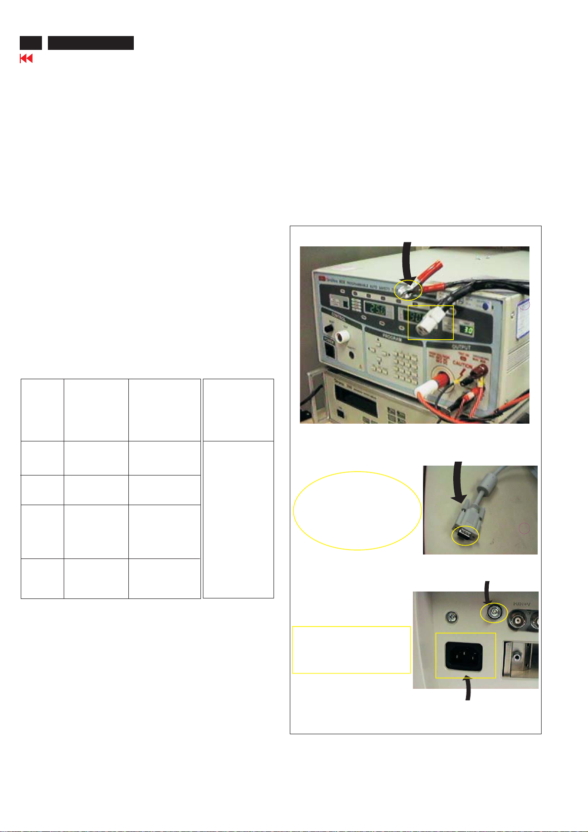
3. Equipments and Connection
3.1. Equipments
For example :
- ChenHwa 9032 PROGRAMMABLE AUTO SAFETY
TESTER
- ChenHwa 510B Digital Grounding Continuity Tester
- ChenHwa 901 (AC Hi-pot test), 902 (AC, DC Hi-pot test)
Withstanding Tester
3.2. Connection
* Turn on the power switch of monitor before Hipot and
Ground Continuity testing.
Clip
Clip
Condition HiPot Test for HiPot Test for Ground Continuity
products where products where Test requirement
the mains input the mains input is
range is Full 110V AC(USA
range(or 220V type)
AC)
Test 2820VDC 1700VDC Test current:
voltage (2000VAC) (1200VAC) 25A,AC
Test time:
Test time 3 seconds 1 second 3 seconds(min.)
(min.) Resistance
required:
Trip set at 100 uA 5 mA <=0.09+Rohm,
current for Max. R is the
(Tester) limitation; set resistance of
at 0.1 uA for the mains cord.
Min. Limitation
Ramp set at 2
time seconds
(Tester)
2.2.1 The minimum test duration for Quality Control Inspector
must be 1 minute.
2.2.2 The test voltage must be maintained within the specified
voltage + 5%.
(ChenHwa 9032 tester)
Video cable
Connect the "video cable"
or "grounding screw"
to the CLIP on your tester.
Grounding screw
Connect the power cord
to the monitor.
2.2.3 There must be no breakdown during the test.
2.2.4 The grounding blade or pin of mains plug must be
conducted with accessible metal parts.
4. Recording
Hipot and Ground Continuity testing records have to be kept
for a period of 10 years.
Power outlet
(Rear view of monitor)
Front View
http://jdwxzlw.com/?fromuser=华盛维修
家电维修资料网,免费下载各种维修资料
Back View
Fig. 1
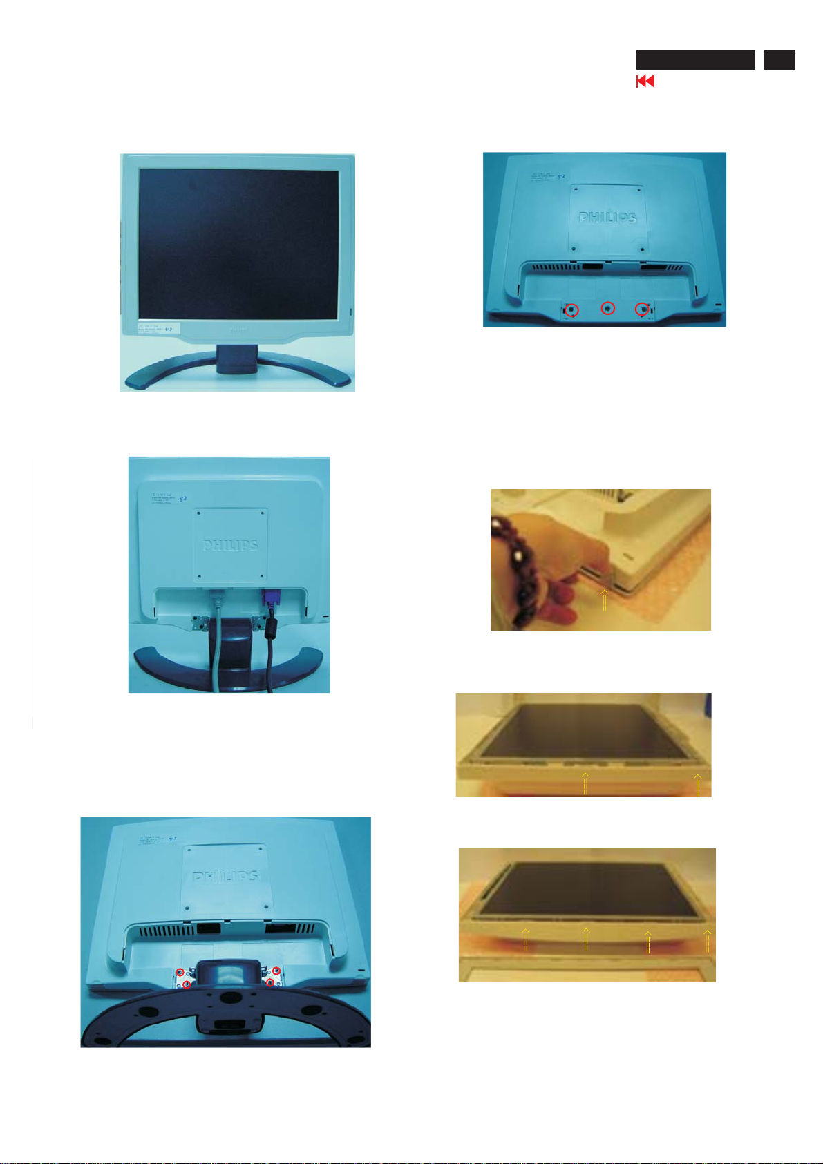
Mechanical Instructions
Step 2: Remove the front bezel
- Use thin "l" type screwdriver to open 2 clicks on bottom
side as shown in Fig. 5.
- Use thin "l" type screwdriver to open 3 clicks on right
and left side as shown in Fig. 6.
- Use thin "l" type screwdriver to open 4 clicks on top
side as shown in Fig. 7.
Fig. 4
150C5 LCD
Go to cover page
13
Fig. 2
Step 1:
-Unscrew the four screws as shown in Fig. 3.
- Remove the base.
- Unscrew the three screws as shown in Fig. 4.
Fig. 5
Fig. 6
Fig. 7
Fig. 3

14
http://jdwxzlw.com/?fromuser=华盛维修
家电维修资料网,免费下载各种维修资料
150C5 LCD
Go to cover page
Mechanical Instructions
Fig. 8
Step 3: Remove the Back Cover shown as Fig. 9 & Fig. 10.
Fig. 9
=========>
1051
3138158601 91
313815860201
SCALER ASSY
LCD Panel
1050 82382771 4731 TFT-LCD MOD LM150X08-A4
1050 9322211 3 5682 TFT-LCD CLAA1 50XP01 (CPT0) B
***************************************************************************
In warranty, it is not allowed to disassembly the LCD panel, even the
backlight unit defect.
Out of warranty, the replacment of backlight unit is a correct way
when the defect is cused by backlight (CCFL,Lamp).
***************************************************************************
=========>
1053
313815860081
CONTROL ASSY
=========>
1052
313819872542
LIPS(ADP-23AF A)
==============>
100
31381 5135901
SHIELD INVERTER
Step4:
- Unscrew on screw, remove the shield inverter as shown in
Fig.10.
- Unscrew seven screws as shown in Fig. 11.
- Unconnect 3 cables as shown in Fig. 11.
Fig. 10
Fig. 10
Front View
http://jdwxzlw.com/?fromuser=华盛维修
家电维修资料网,免费下载各种维修资料
How to enter Factory Mode
Factory Mode & Aging Mode
HUDSON 150C5 V200 20040705
HS 1.LG (7) 2. CPT (28) 3. HS (28) 4. QDI (28)
150C5 LCD
Go to cover page
7
15
1. Turn off the monitor.
2. [Push "AUTO "&"OK" buttons at the same time and hold it
] + [Press power ""button until comes out "Windows screen"]
=> then release all button, then press , wait until the
OSD menu with Characters HUDSON 150C5 V002 20040511
(below OSD menu) come on the Screen of the monitor
(see Fig. 2).
Factory Mode
Factory Menu
Cursor can move on gray color area
BL : Black level value
SUB- BRI : Brightness value range( Min Max)
SUB- CON : Contrast value range( Min Mid Max )
SRGB- B : Brightness of sRGB
SRGB- C : Contrast of sRGB
Gain- m : Minimum value of User Gain
Gain- M : Maximum value of User Gain
AUTO- SUB : To do Auto color function when push Menu key in white
OSD TIMER: OSD time out control(sec)
IDX : Limit current of inverter (CPT: 28) (LG:7)
Panel TYPE :PLS reference section 2.9.6
SCALER : Read/Write scaler register
Panel : HS (Hannstar panel)
---------->
Indicator
HUDSON 150C5 V002 20040511
pattern
CPT (CPT panel)
LG (LG. Philips panel)
"OK" button
How to Access Aging Mode
Step 1 : Turn off LCD monitor, and disconnect Interface Cable between Monitor and PC.
Step 2 : [Push "AUTO"&"OK " buttons at the same time and hold it]
+[Press power ""button untill comes out " AGING screen"] =>
then release all buttons.
Bring up:
AGING...
After 15 seconds,
bring up:
After 15 seconds,
bring up:
After 15 seconds,
bring up:
----------
---------repeatly
Connect Signal cable again=> go back to normal display
AGING...
16
http://jdwxzlw.com/?fromuser=华盛维修
家电维修资料网,免费下载各种维修资料
150C5 LCD
Go to cover page
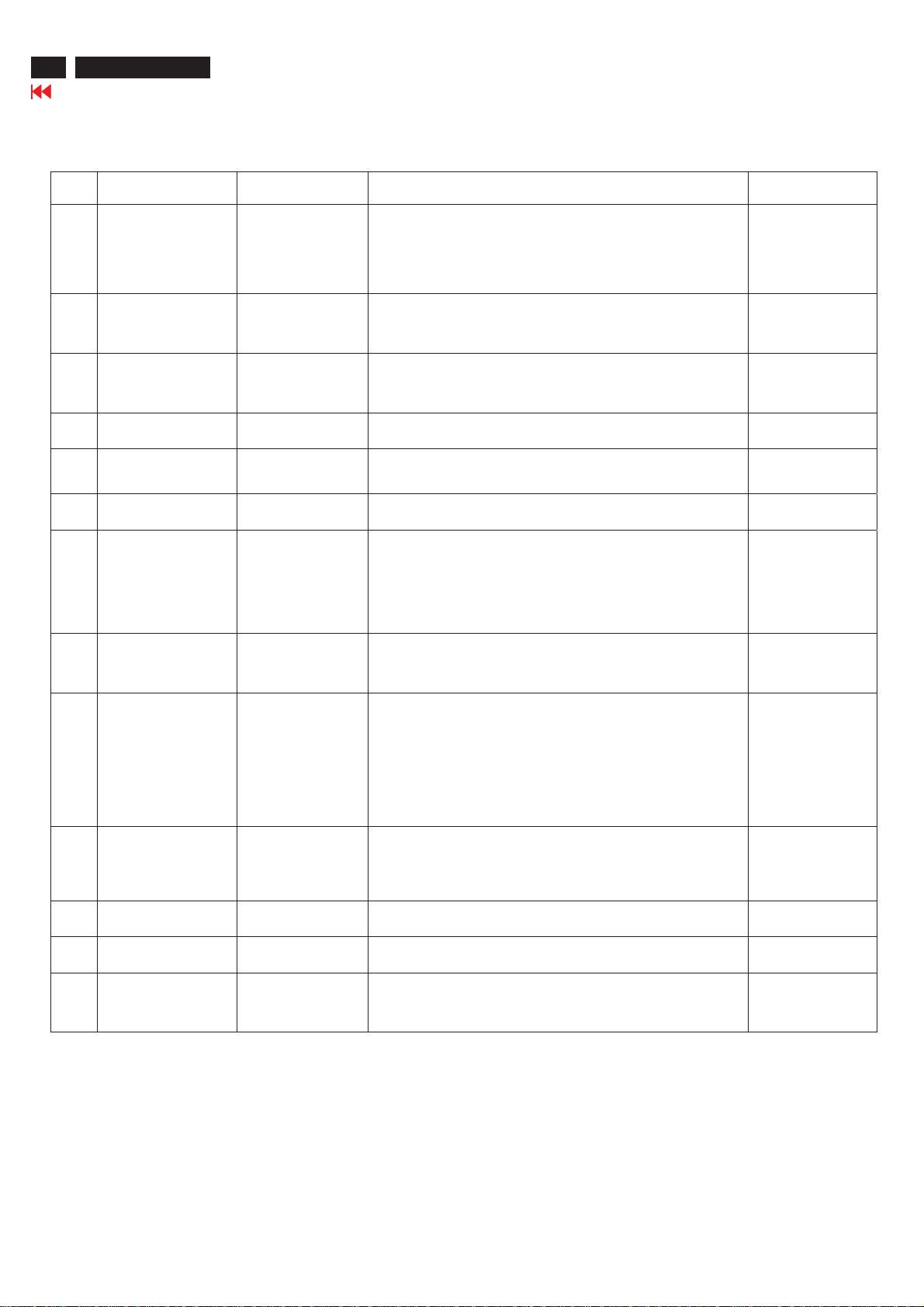
Warning Message
Item
Attention Signals
CANNOT DISPLAY
THIS VIDEO MODE,
CHANGE COMPUTER
1
DISPLAY
INPUT TO 1024 X 768
@60Hz
NO VIDEO INPUT
2
CHECK CABLE
CONNECTION
3
4
ENTER SLEEP MODE
WAITING FOR
5
AUTOMATIC
ADJUSTMENT
USE 1024 x 768 FOR
6
BEST RESULT
OSD MAIN CONTROLS
LOCKED
7
OSD MAIN CONTROLS
UNLOCKED
8
ATTENTION SIGNAL
ON
9
Display Time
30 mins
30 mins
30 mins
3 secs
Till auto adjustment
finished
On top of OSD main
menu
3 secs / or till "OSD
MAIN CONTROLS
UNLOCKED" appear
3 secs
3 secs
Condition
This warning appears when the input signal from your computer
is not in a standard video mode or is out of the monitor's scanning
range. After 30 mins, monitor enters sleeping mode.
This message appears when there is no signal input but with cable
while AC to DC while power on. After 30 mins, monitor enters
sleeping mode.
This message appears when a signal cable is disconnected while
monitor is working. After 30 mins, monitor enters sleeping mode
This message appears when monitor is about to enter power
saving mode.
This message is displayed when the auto adjustment button is
pressed. It disappears when automatic adjustments are completed.
The message will show up at the top of the OSD main menu in
red color when the input resolution is not the 1024 X 768.
This message will appear 3 seconds to indicate the OSD MAIN
CONTROLS status when to lock or un-lock it by pressing
"MENU(OK)" button for more than 10 seconds while there is
video input from PC. This function provides the alternative that
user can lock all the OSD main control in case user don't want
the OSD performance setting to be changed, for instance, during
commercial exhibition.
This message will appear 3 seconds to indicate the OSD MAIN
CONTROLS status when to lock or un-lock it by pressing
"MENU(OK)" button for more than 10 seconds while there is video
input from PC.
This message will appear 3 seconds to indicate the attention
signals in ON or OFF status when to switch this function on or off
by pressing the AUTO button for more than 10 seconds while at
no video input from PC.
Active off
No
Yes
show floating menu
"ATTENTION
SIGNAL OFF"
Yes
show floating menu
"ATTENTION
SIGNAL OFF"
No
No
Yes
No function when
push 10 secs (if OSD
lock then attention off,
not any message and
only attention on)
function when
No
push 10 secs.
Yes
ATTENTION SIGNAL
OFF
THIS IS 85 Hz
OVERSCAN, CHANGE
10
COMPUTER DISPLAY
INPUT TO
1024 X 768@60Hz
The window of " OSD
11
MAIN CONTROLS"
12
13
The window of
"brightness"
"SELECTED INPUT NOT
AVAILABLE"
3 secs
10 mins
60 secs
60 secs
5 secs
This message will appear 5 seconds in every 60 seconds for 10
minutes when the input of PC video timing is at 85 Hz mode.
Remark: AUTO is still functional in this mode.
This message will appear when the "OK" button is pressed.
This message will appear when the "BRIGHTNESS" button is
pressed.
When just on input(analog or digital), press"input switch" or
hot key, then after show this warning message 5 sec, return to
original input.
No
Yes
Yes
TBD
Repair Tips
http://jdwxzlw.com/?fromuser=华盛维修
家电维修资料网,免费下载各种维修资料
150C5 LCD
Go to cover page
17
0. Warning
All ICs and many other semi-conductors are susceptible to
electrostatic discharges (ESD). Careless handling during
repair can reduce life drastically. When repairing, make sure
that you are connected with the same potential as the mass
of the unit via a wrist wrap with resistance. Keep components
and tools also at the same potential !
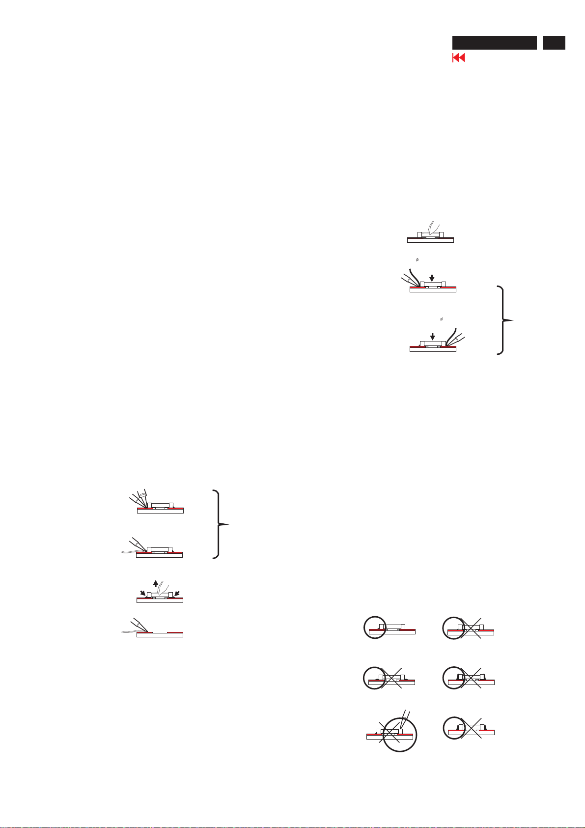
1. Servicing of SMDs (Surface Mounted Devices)
1.1 General cautions on handling and storage
- Oxidation on the terminals of SMDs results in poor soldering.
Do not handle SMDs with bare hands.
- Avoid using storage places that are sensitive to oxidation
such as places with sulphur or chlorine gas, direct sunlight,
high temperatures or a high degree of humidity. The
capacitance or resistance value of the SMDs may be
affected by this.
- Rough handling of circuit boards containing SMDs may
cause damage to the components as well as the circuit
boards. Circuit boards containing SMDs should never be
bent or flexed. Different circuit board materials expand and
contract at different rates when heated or cooled and the
components and/or solder connections may be damaged
due to the stress. Never rub or scrape chip components as
this may cause the value of the component to change.
Similarly, do not slide the circuit board across any surface.
1.2 Removal of SMDs
- Heat the solder (for 2-3 seconds) at each terminal of the
chip. By means of litz wire and a slight horizontal force,
small components can be removed with the soldering iron.
They can also be removed with a solder sucker (see Fig.
1A)
SOLDERING
IRON
E.g. WELLER
SOLDER TIP PT-H7
SOLDERING
IRON
SOLDER WICK
4822 321 40042
SOLDERING
IRON
SOLDER WICK
- While holding the SMD with a pair of tweezers, take it off
gently using the soldering iron's heat applied to each
terminal (see Fig. 1 B).
- Remove the excess solder on the solder lands by means of
litz wire or a solder sucker (see Fig. 1C).
Fig. 1 DISMOUNTING
VACUUM PISTON
4822 395 10159
E.g. A PAIR OF TWEEZERS
HEATING
A
HEATING
B
C
1.3 Caution on removal
- When handling the soldering.iron. use suitable pressure and
be careful.
- When removing the chip, do not use undue force with the
pair of tweez ers.
-Thesolderingirontobeused(approx.30W) should
Preferably be equipped with a thermal control
(soldering temperature: 225 degree V to 250 degree C.
-The chip, once removed, must never be reused.
1.4 Attachment of SMDs
-Locate the SMD on the solder lands by means of tweezers
and solder the component on one side. Ensure that the
component is positioned correctly on the solder lands (see Fig. 2A)
-Next complete the soldering of the terminals of the component.
(See Fig. 2B)
Fig. 2 MONUTING
E.g. A PAIR OF TWEEZERS
A
SOLDER
0.5-0.8 mm
PRESURE
PRESURE
SOLDER
0.5-0.8 mm
SOLDERING
IRON
B
SOLDERING
IRON
SOLDERING TIME
< 3 sec/side
2. Caution when attaching SMDs
- When soldering the SMDs terminals, do not touch them
directly with the soldering iron. The soldering should be
directly with the soldering iron. The soldering should be
done as quickly as possible, care must be taken to avoid
damage to the terminals of the SMDs themselves.
- Keep the SMD's body in contact with the printed board
when soldering.
- The soldering iron to be used (approx. 30W) should
preferably be equipped with a thermal control (soldering
temperature: 225 degree C to 250 degree C).
- Soldering should not be done outside the solder land.
- Soldering flux (of rosin) may be used, but should not
be acidic.
- After soldering, let the SMDs cool down gradually at room
temperature.
- The quantity of solder must be proportional to the size of
the solder land. If the quantity is too great, the SMD might
crack or the solder lands might be torn loose from the
printed board (See Fig. 3).
Fig. 3 Examples
RIGHT
SOLDERING
IRON
18
http://jdwxzlw.com/?fromuser=华盛维修
家电维修资料网,免费下载各种维修资料
150C5 LCD
Go to cover page
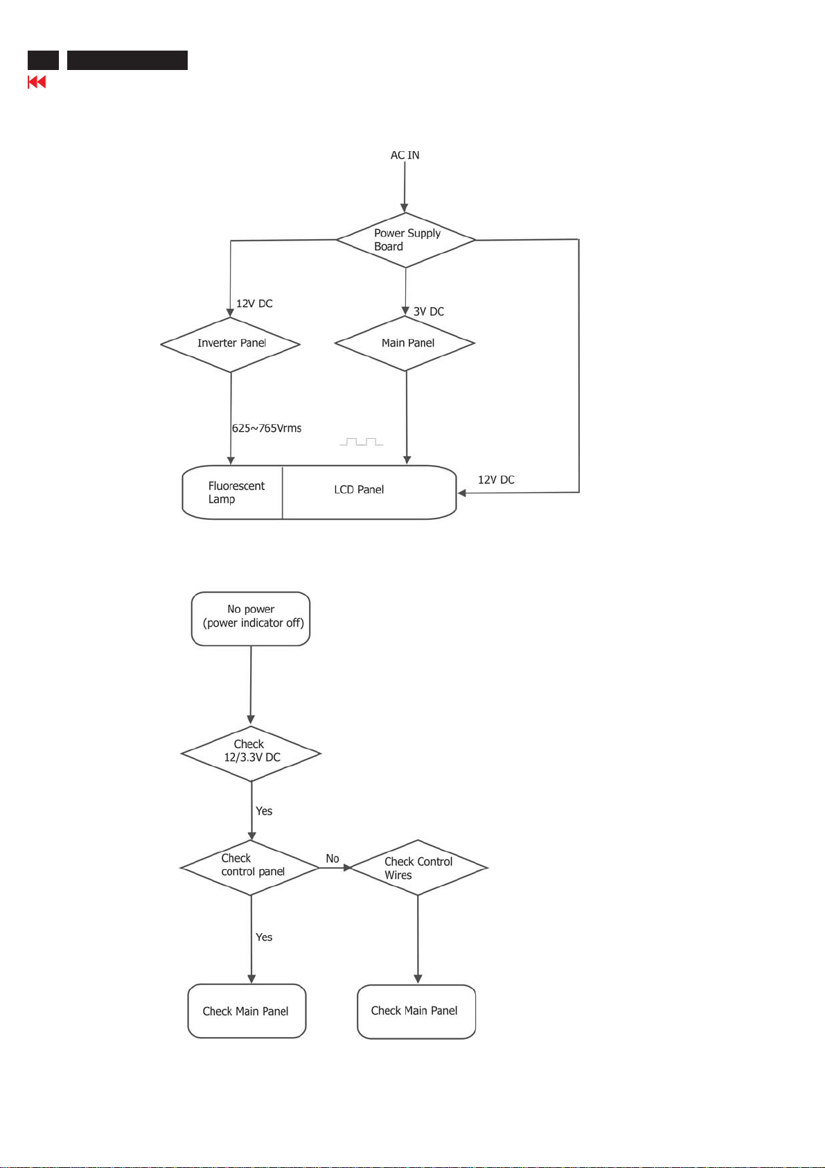
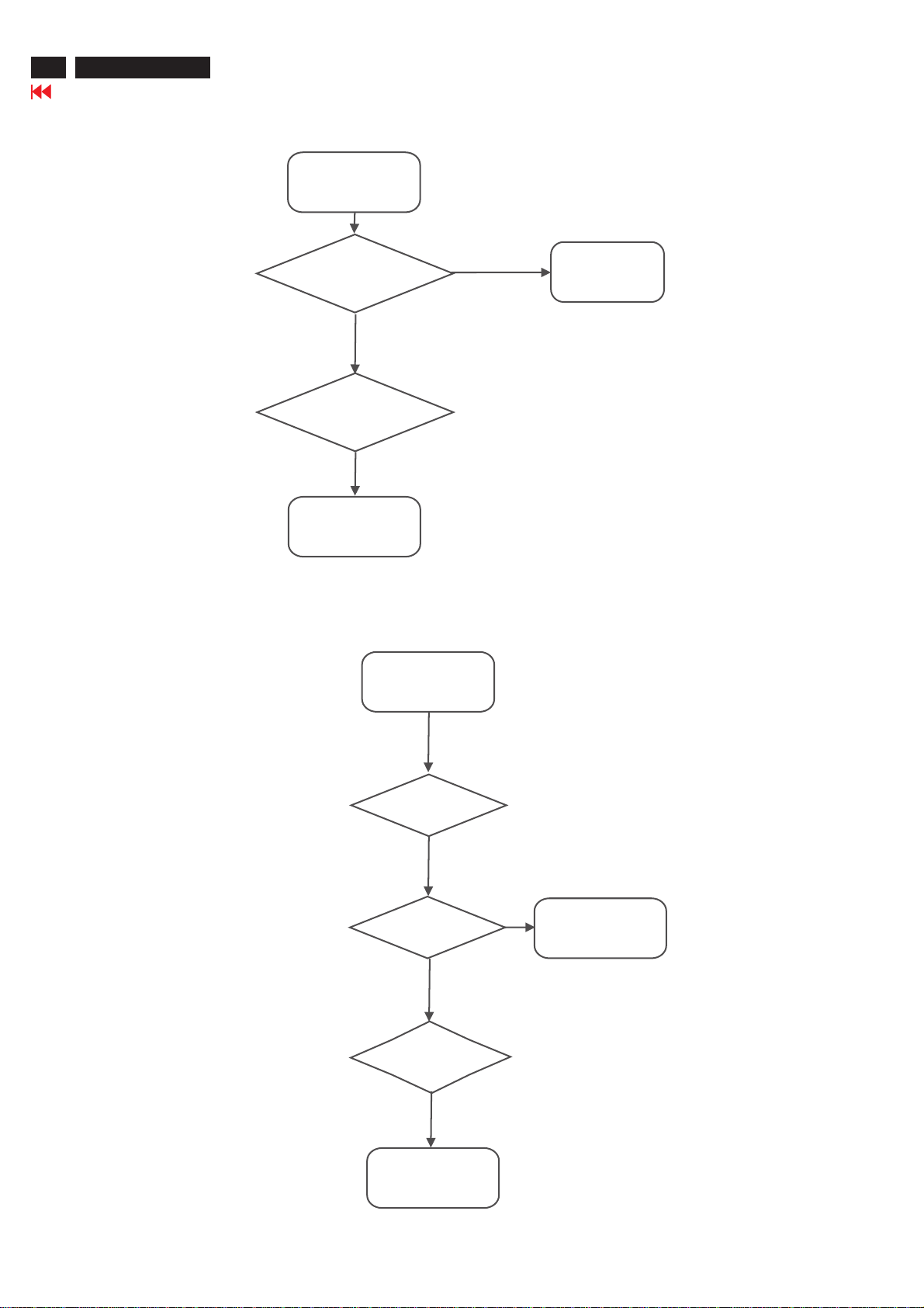
Repair Flow Chart

Repair Flow Chart-2
http://jdwxzlw.com/?fromuser=华盛维修
家电维修资料网,免费下载各种维修资料
No Display
Check Mains cord
& LED of Monitor
Check
Power board
12V/3.3V DC
Yes
150C5 LCD
Go to cover page
19
Check
video signals input
interface
Yes
Check
Inverter panel
625~765Vrms with load
No
Check inverter
panel
No
OK
No
Front control key
does not work
Check main panel
Video source
Check fluorescent
lamp
Check
Front control panel
(Key & SW)
Yes
Check
Signal connectors
Yes
Check main panel
20
http://jdwxzlw.com/?fromuser=华盛维修
家电维修资料网,免费下载各种维修资料
150C5 LCD
Go to cover page
Repair Flow Chart-3
Bad brightness
Check
Inverter panel output
625~765Vrms
Yes
Check fluorescent
lamp
No
Check LCD panel
Bad image
No
Bad Inverter
panel
Check
Video, fh/fv
signals
Yes
Check main panel
No
Check
all connectors &
LVDS cable
No
Check LCD panel
Yes
Check components
cold soldering
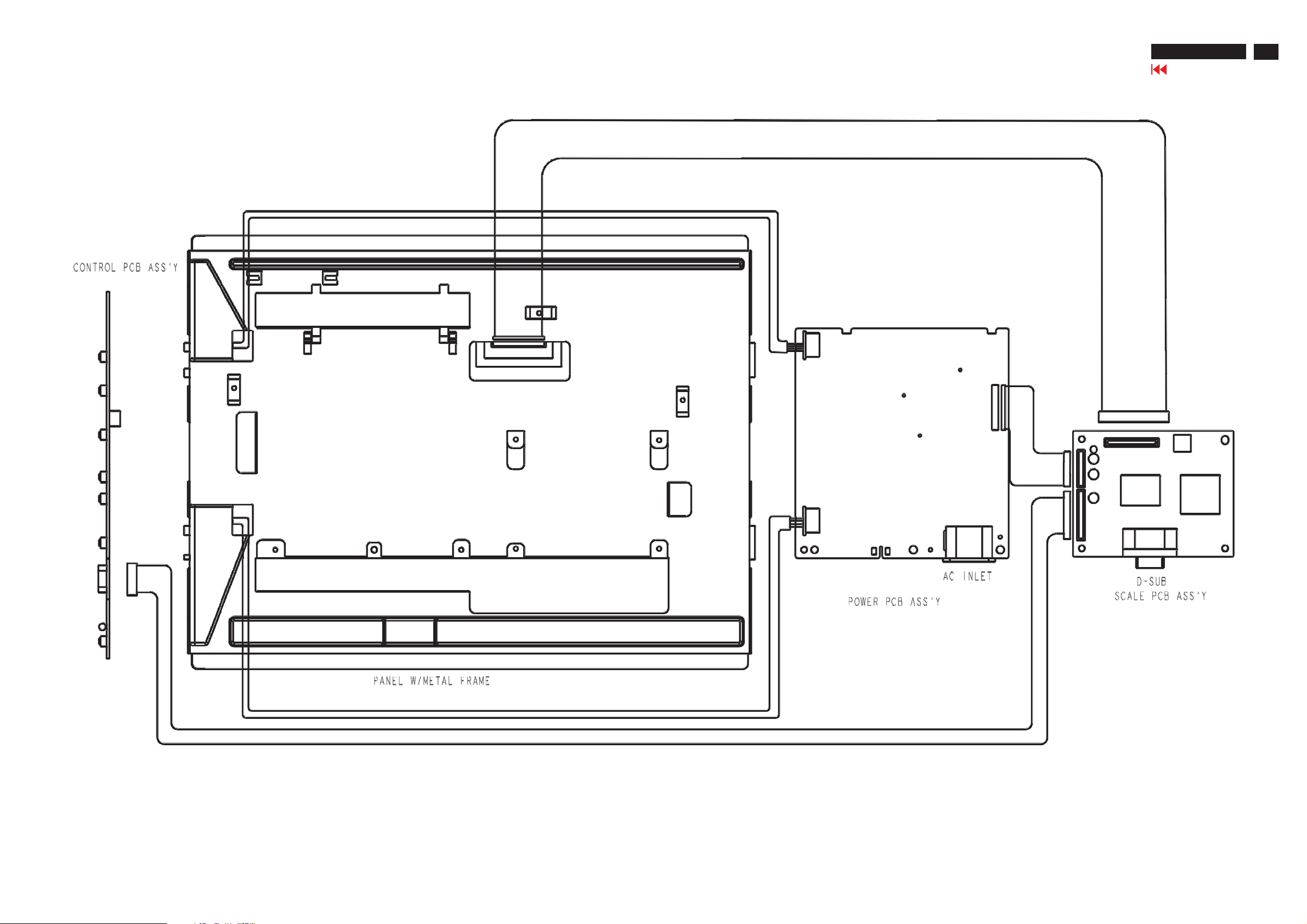
Wiring Diagram
http://jdwxzlw.com/?fromuser=华盛维修
家电维修资料网,免费下载各种维修资料
150C5 LCD
Go to cover page
21
 Loading...