

Philips Hudson2 200P3, 200P3G/00C Service Manual
20" TFT LCD Colour Monitor- Hudson2 200P3
Horizontal frequencies
30-82kHz
Service
Service
Service
TABLE OF CONTENTS
Published by BCU Monitor Printed in Taiwan Copyright reserved Subject to modification Oct , 03 2002
DDC/Power saving/Auto Picture Adjustment
Description Page
Important Safety Notice ---------------------------------- 2
Technical Data ------------------------------------------ 3~4
Connection to PC, Front Control------------------------ 5
Front Control,Base,Accessory Pack------------------- 6
Settings using the OSD menu---- -- -------------------- 7
OSD Attention signals-------------------------------------9
OSD menu tree - Analog---------------------------------10
OSD menu tree - Digital----------------------------------11
OSD Lock/Unlock, Aging mode------------------------ 12
Clock & Phase Adjustments-----------------------------13
DDC Hex Data---------------------------------------- 21~22
Wiring Diagram--------------------------------------------24
Mechnical
Advanced control of OSD, Factroy mode--------------8
DDC Instructions------------------------------------- 14~20
Serinal number application------------------------------23
Instructions------------------------------ 25~26
Warning and Notes----------------------------------------27
Electrical Instruction------------------ ---------------28~30
Block Diagram----------------------------------------------31
Scaler Panel(Components &Copper track)------32~33
Description Page
Scaler Diagram---------------------------------------34~42
Power Panel(C.B.A.)------------------------------------ 43
Power Diagram------------------------------------------- 44
Audio &Keypad Panel----------------------------------- 45
Audio & Mic Preamp Diagram---------------------46~47
Phone Jack Board(C.B.A.),&Diagram----------- 48~49
Inverter Panel(C.B.A.)-----------------------------------50
Inverter Diagram(AMBIT)-------------------------- 51~52
Failure Mode of LCD Panel-----------------------------53
Exploded View ------------------------------------------- 54
Recommended
Difference Parts List-------------------------------------60
Repair Flow Chart-----------------------------------61~63
Repair Tips------------------------------------------------64
CA110 Application----------------------------------65~73
Firmware upgrade for CPU------------------------74~76
General Product Specification--------------------77~99
Safety Test Requirements-----------------------------100
General troubleshooting Guide---------------------------
parts list--------------------------------55
Spare parts list-------------------------------------- 56~59
REFER TO BACK COVER FOR IMPORTANT SAFETY GUIDELINES
CAUTION: USE A SEPARATE ISOLATION TRANSFORMER FOR THIS UNIT WHEN SERVICING.
ANY PERSON ATTEMPTING TO SERVICE THIS CHASSIS MUST FAMILIARIZE HIMSELF WITH THE CHASSIS
AND BE AWARE OF THE NECESSARY SAFETY PRECAUTIONS TO BE USED WHEN SERVICING ELECTRONIC
EQUIPMENT CONTAINING HIGH VOLTAGES.
SAFETY NOTICE
GB
3138 106 10237
200P3G/00C
Important Safety Notice
2
FOR PRODUCTS CONTAINING LASER :
Invisible laser radiation when open.
AVOID DIRECT EXPOSURE TO BEAM.
Use of controls or adjustments or
performance of procedures other than
those specified herein may result in
hazardous radiation exposure.
The use of optical instruments with this
product will increase eye hazard.
DANGER-
CAUTION-
CAUTION-
TO ENSURE THE CONTINUED RELIABILITY OF THIS
PRODUCT, USE ONLY ORIGINAL MANUFACTURER'S
REPLACEMENT PARTS, WHICH ARE LISTED WITH THEIR
PART NUMBERS IN THE PARTS LIST SECTION OF THIS
SERVICE MANUAL.
Proper service and repair is important to the safe, reliable
operation of all PHILIPS Consumer Electronics Company**
Equipment. The service procedures recommended by
PHILIPS and described in this service manual are effective
methods of performing service operations. Some of these
service operations require the use of tools specially designed
for the purpose. The special tools should be used when and
as recommended.
It is important to note that this manual contains various
CAUTIONS and NOTICES which should be carefully read in
order to minimize the risk of personal injury to service
personnel. The possibility exists that improper service
methods may damage the equipment. It is also important to
understand that these CAUTIONS and NOTICES ARE NOT
EXHAUSTIVE. PHILIPS could not possibly know, evaluate
and advise the service trade of all conceivable ways in which
service might be done or of the possible hazardous
consequences of each way. Consequently, PHILIPS has not
undertaken any such broad evaluation. Accordingly, a
servicer who uses a service procedure or tool which is not
recommended by PHILIPS must first satisfy himself
thoroughly that neither his safety nor the safe operation of the
equipment will be jeopardized by the service method selected.
* * Hereafter throughout this manual, PHILIPS Consumer
Electronics Company will be referred to as PHILIPS.
Critical components having special safety characteristics are
identified with a by the Ref. No. in the parts list and
enclosed within a broken line*
(where several critical components are grouped in one area)
along with the safety symbol on the schematics or
exploded views.
Use of substitute replacement parts which do not have the
same specified safety characteristics may create shock, fire,
or other hazards.
Under no circumstances should the original design be
modified or altered without written permission from Philips.
Philips assumes no liability, express or implied, arising out of
any unauthorized modification of design.
Servicer assumes all liability.
WARNING
* Broken Line
Take care during handling the LCD module with backlight
unit
- Must mount the module using mounting holes arranged in four
corners.
- Do not press on the panel, edge of the frame strongly or electric
shock as this will result in damage to the screen.
- Do not scratch or press on the panel with any sharp objects, such
as pencil or pen as this may result in damage to the panel.
- Protect the module from the ESD as it may damage the electronic
circuit (C-MOS).
- Make certain that treatment person s body are grounded through
wrist band.
- Do not leave the module in high temperature and in areas of high
humidity for a long time.
- Avoid contact with water as it may a short circuit within the module.
- If the surface of panel become dirty, please wipe it off with a soft
material. (Cleaning with a dirty or rough cloth may damage the
panel.)
Go to cover page
Hudson2 200P3
3
Technical Data
Go to cover page
Technical Specifications
LCD PANEL
SCANNING
VIDEO
AUDIO-IN
MICROPHONE
Optical characteristics
Type :TFT LCD
Screen size :20.1" /51cm
Pixel Pitch :0.255 x0.255mm
LCD Panel type :1600 x 1200 pixels
R.G.B. vertical stripe
Anti-glare polarizer, hard coated
Effective viewing area :408 x 306mm
Display Colors :8 bits interface (16M colors)
Vertical refresh rate :56Hz-85Hz
Horizontal Frequency :30kHz-94kHz (Analog input),
:30kHz-92kHz(Digital input)
Video dot rate :202MHz
Input impedance
- Video :75 Ohm
- Sync :2K Ohm
Input signal levels :0.7 Vpp
Sync input signal :Separate sync
:Composite sync
:Sync on green
Sync polarities :Positive and negative
S-Video :Y input 1.0Vpp, C input 0.3Vpp,75ohm
input impedance
CVBS :Composite, 1.0Vpp,75ohm input
impedance
Video interface :Triple input(two connectors): D-Sub(analog)
and DVI-I(accepts both digital and analog) are
available and user selectable S-Video &CVBS
Input signal level :0.7 Vpp
Headphone out signal level :32 20+20mW
Input signal connector :3.5mm mini jack
Loudspeaker :4W Stereo Audio (2W/channel
RMSx2, 200Hz-12kHz,
4ohm,THD=10%)
Sensitivity :-45dB re 1V/ubar at 1kHz
Output impedance :2.2K max
Directivity :-5dB at 180
Frequency range :300Hz-3kHz
Contrast ratio : 300 (typ.)
Brightness :250 cd/m (typ.)
Peak contrast angle :6 o'clock
White Chromatcity: x: 0.281 y: 0.311 (at 9300 K)
x: 0.312 y: 0.338 (at 6500 K)
Viewing Angle:
(C/R>10)
Response time 30ms (typ.)
2
Upper 85 (typ.)
Lower 85 (typ.)
Left 85 (typ.)
Right 85 (typ.)
>
>
>
>
<
Physical Specifications
Dimension (WxHxD) :488 x 459 x220 mm (incl. Pedestal)
Weight :10.0 Kg
Tilt / Swivel :-5 ~ 25 /+-175
Power supply :100 240 VAC, 50/60 Hz
Power consumption :52 W (typ.)
Temperature :5 C to 35 C (operating)
:-20 C to 60 C (storage)
Relative humidity :20% to 80%
System MTBF :50K hrs (including CCFL 40K hrs)
Cabinet color :200P3M: Light Gray
200P3G: Black
Pin
No.
Signal
Assignment
Pin
No.
Signal
Assignment
Pin
No.
Signal
Assignment
Pin
No.
Signal
Assignment
1 TMDS Data 2- 9 TMDS Data 1- 17 TMDS Data 0- C1
Analog Red
Video Out
2 TMDS Data 2+ 10 TMDS Data 1+ 18 TMDS Data 0+ C2
Analog Green
Video Out
3
TMDS Data 2/4
Shield
11
TMDS Data 1/3
Shield
19
TMDS Data
0/5 Shield
C3
Analog Blue
Video Out
4 TMDS Data 4- 12 TMDS Data 3- 20 TMDS Data 5- C4
Analog
Horizontal Sync
5 TMDS Data 4+ 13 TMDS Data 3+ 21 TMDS Data 5+ C5
Analog
Common
Ground Return
(Red, Green,
Blue Video Out)
6 DDC Clock 14 +5V Power 22
TMDS Clock
Shield
7 DDC Data 15
Ground (+5V,
Analog H/V
Sync)
23 TMDS Clock+
8
Analog Vertical
Sync
16 Hot Plug Detect 24 TMDS Clock-
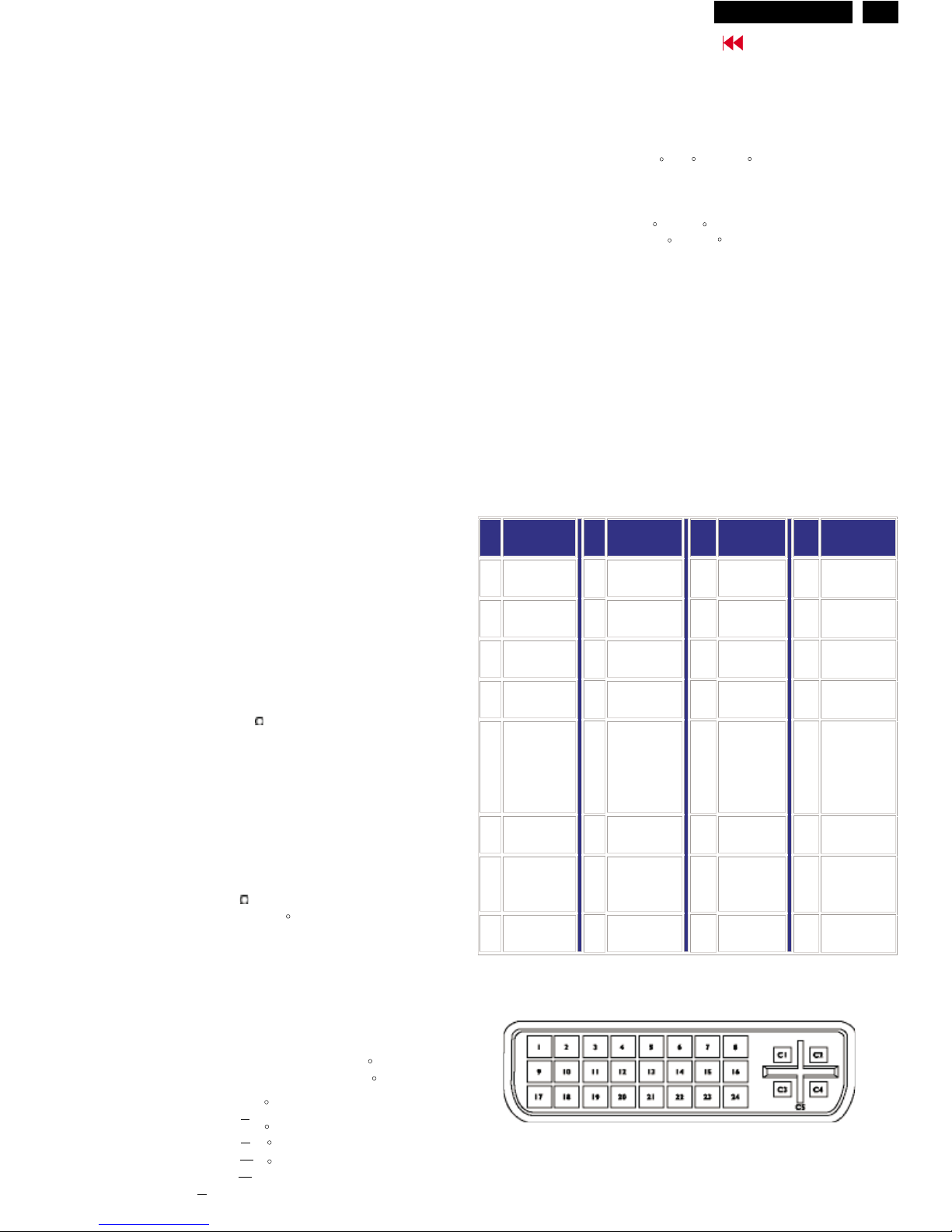
Pin Assignment
1. The digital/analog DVI-I onnector contains 29
signal contacts organized in three rows of eight
contacts. Signal pin assignments are listed in the
Hudson2 200P3
Technical Data(Continued)
4
Go to cover page
Pin
No.
Assignment
Pin
No.
Assignment
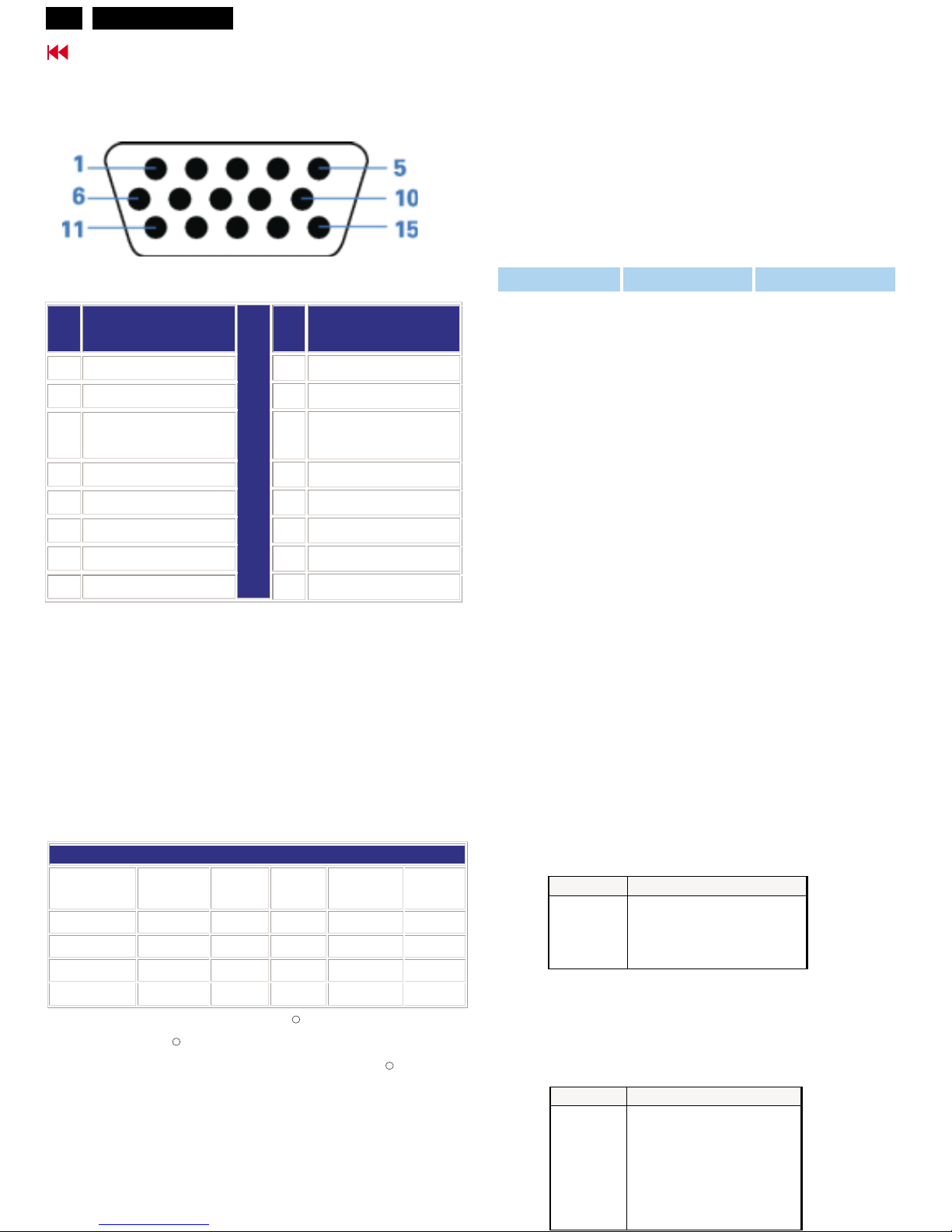
1 Red video input 9 +5V
2 Green video input/SOG 10 Logic ground
3 Blue video input 11
Identical output -
connected to pin 10
4 Sense (GND) 12 Serial data line (SDA)
5 Not connected 13 H. Sync / H+V
6 Red video ground 14 V. Sync (VCLK for DDC)
7 Green video ground 15 Data clock line (SCL)
8 Blue video ground
2. The 15-pin D-sub connector (male) of the signal cable:
Automatic Power Saving
If you have VESA's DPMS compliance display card or
software installed in your PC, the monitor can
automatically reduce its power consumption when
not in use. And if an input from a keyboard, mouse or
other input device is detected, the monitor will
automatically "wake up". The following table shows
the power consumption and signaling of this
automatic power saving features:
Power Management Definition
VESA Mode Video H-sync V-sync Power Used LED color
ON Active Ye s Yes < 60W Green
Stand-by Blanked No Ye s <3W Amber
Suspend Blanked Ye s No <3W Amber
OFF Blanked No No <3W Amber
This monitor is NERGY TAR compliant. s an
NERGY TAR artner, has determined
that this product meets the NERGY TAR
guidelines for energy efficiency.
ES A
E S P PHILIPS
ES
R
R
R
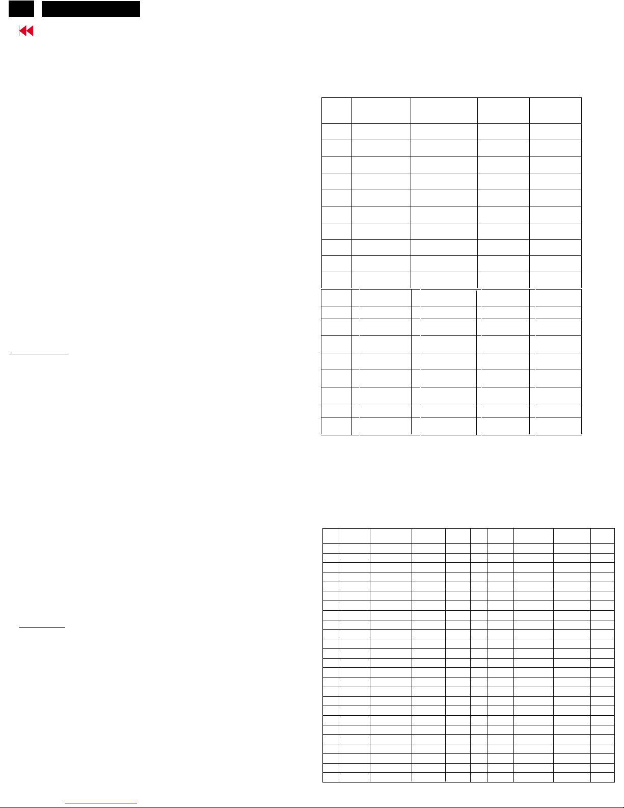
50 user definable modes
Maximum
1600 x 1200 at 75Hz(analog input)
1600 x 1200 at 60Hz(digtal input)
Recommended 1600 x 1200 at 60Hz
18 factory preset modes:
H. freq (kHz) Resolution V. freq (Hz)
31.5 640*350 70 (IBM VGA 10h)
31.5 720*400 70
31.5 640*480 60
35.0 640*480 67
37.5 640*480 75
35.2 800*600 56
37.9 800*600 60
46.9 800*600 75
49.7 832*624 75
48.4 1024*768 60
60.0 1024*768 75
69.0 1152*870 75
71.8 1152*900 76 (SUN Mode II)
63.9 1280*1024 60
80 1280*1024 75
91.1 1280*1024 85
75.0 1600*1200 60
93.8 1600*1200 75
Resolution & Preset Modes
PIN NO. SIGNAL
1
GND
2 CVBS
3 CVBS
4 CVBS
PIN NO. SIGNAL
1
GND
2 GND
3 LUMA
4 CHROMA
5 GND
6 GND
7 GND
S-Video
The input signals are applied to display through S-Video
cable
pin assignment
CVBS
The input signals are applied to display through CVBS
cable
pin assignment
Hudson2 200P3
5
Go to cover page
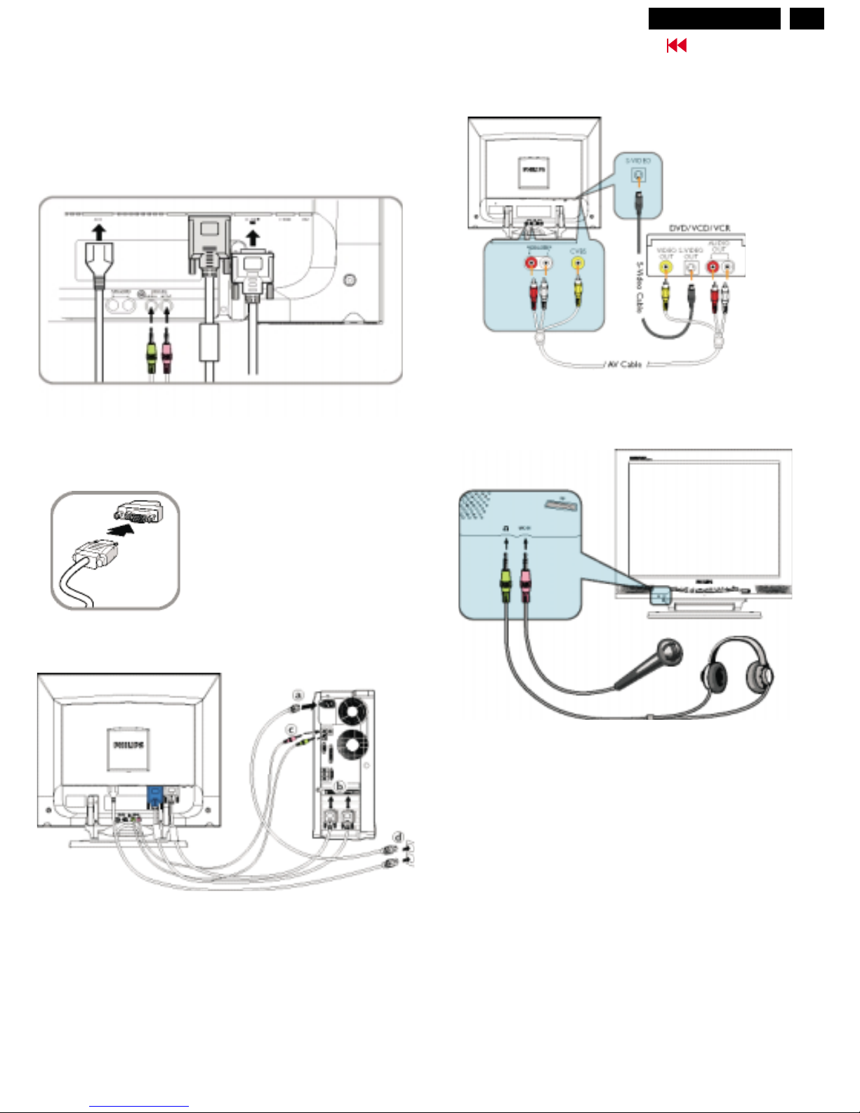
Connection to PC,Front Control
Connect to PC
Philiips has pre-connected VGA cable for the first installation.
Connect power cord, VGA, DVI, microphone and audio cables onto rear of
monitor firmly
Connect the cables to the back of your computer by following steps
(a) Turn off your computer and unplug its power cord.
(b) Connect the VGA or DVI cable to video connector.
(c) Connect the microphone and audio cables.
(d) Plug the power cord of computer and monitor into a nearby outlet.
(e) Turn on your computer and monitor. If the monitor displays an image,
installation is complete.
Connect to DVD/VCR/VCD
Connect to Microphone and Earphone
If you use an Apple MacintoshTM, you need to connect the special Mac adapter
to one end of the monitor signal cable.
Hudson2 200P3
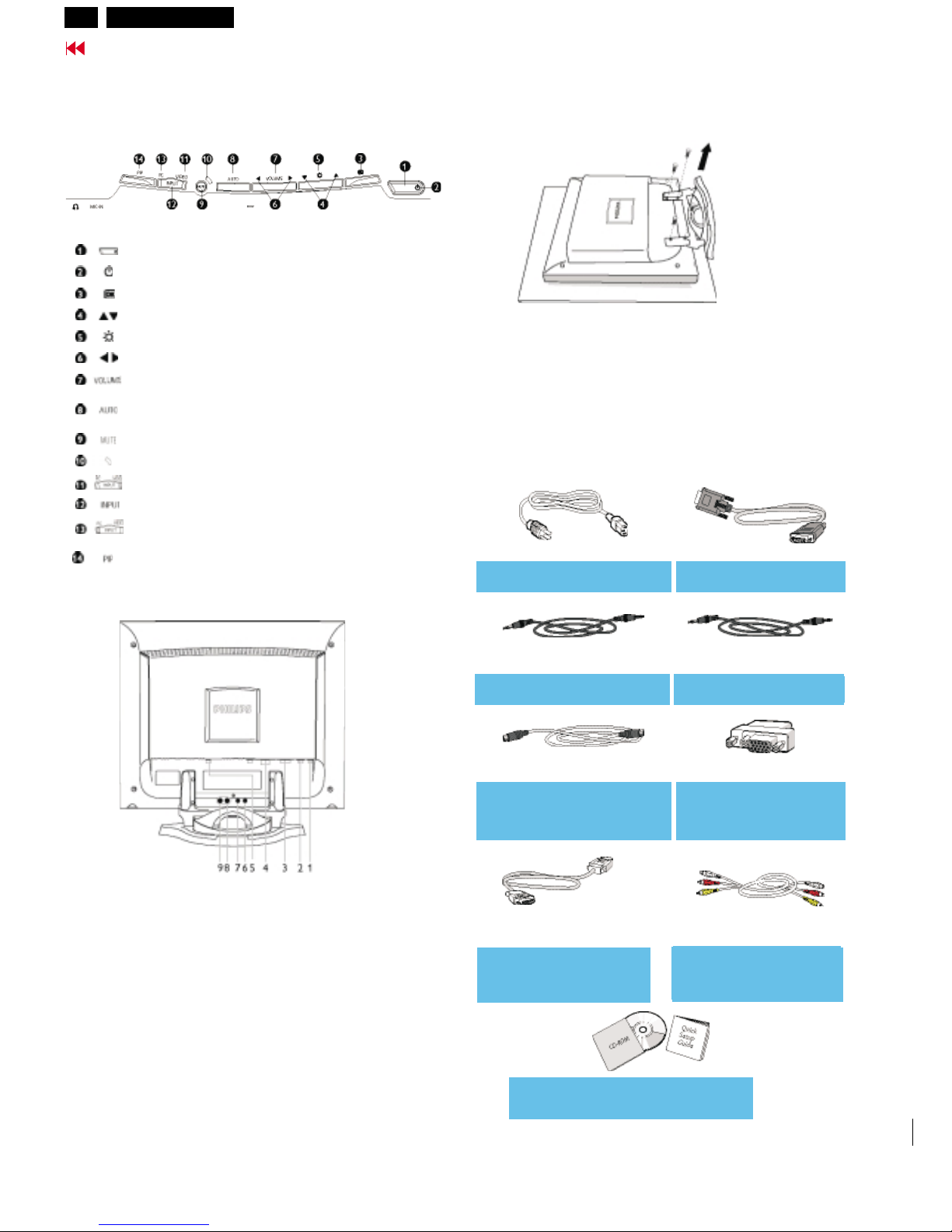
Front Control , Base
6
Go to cover page
Removing the monitor base
Front View Product Description
Rear View
To switch monitor's power On and Off
Power LED
To access OSD menu
To adjust the OSD
To adjust brightness of the display
To adjust the OSD
To adjust speakers volume
Automatically adjust the horizontal position, vertical pos
ition,
phase and
clock setting
To mute the audio sound
MUTE LED
Video input LED, lit when CVBS or S-Video activated
Signal inputs selection
PC input LED, lit when VGA or DVI activated
Activated PIP (
Picture in Picture) window
1 CVBS video input
2 S-Video video input
3 VGA input
4 DVI-I input
5 AC power in
6 Mic out
7 Audio in
8 Audio L input
9 Audio R input
The monitor surface is susceptible to scratching!
Lay the monitor on its face on a soft surface.
Remove the four screws on the rear of the monitor.
Accessory Pack
Unpack all the parts.
Power cord VGA signal cable
PC audio cable (lime) Mic cable (pink)
S-video cable
Mac adaptor
DVI to D-Sub
AV cable
(optional)
signal cable
(white/red/yellow)
EDFU pack
3138 128 74931
3138 188 72261(BLK)
3138 188 72051(white)
3138 188 75051(BLK)
3138 188 75031(white)
3138 188 74551(BLK)
3138 188 74541(white)
2422 033 00265
3138 188 74531(BLK)
3138 188 74521(white)
3138 188 75061(BLK)
3138 188 75041)white)
3138 188 72251(BLK)
3138 188 72241(white)
3138 117 04281
Hudson2 200P3
7
Go to cover page
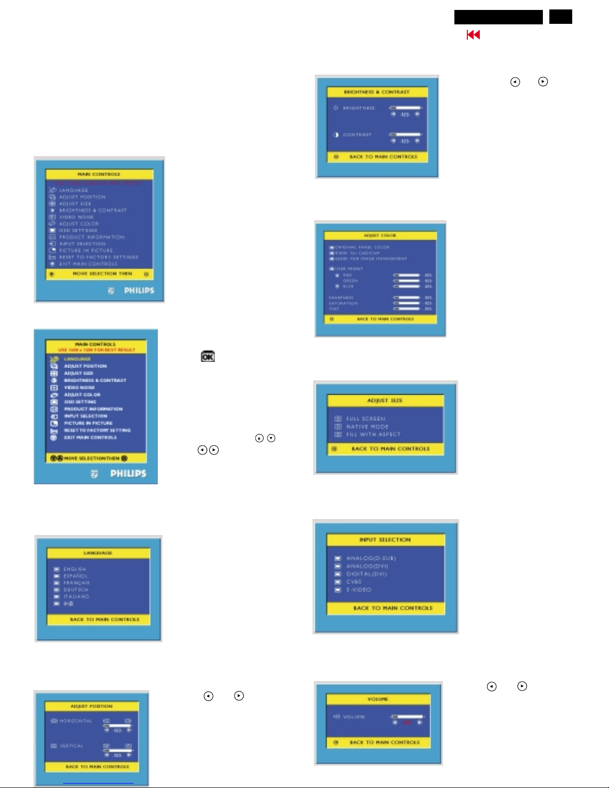
Settings using the OSD menu
Setting the colour temperature
Description of the On Screen Display
This is a feature in all Philips LCD monitors which
allows an end-user to adjust screen performance of
monitors directly through an on-screen instruction
window. The user interface provides userfriendliness and ease-of-use when operating the
monitor.
On the front controls of
your monitor, once you
press the button,
the On Screen Display
(OSD) Main Controls
window will pop up and
you can now start
making adjustments to
your monitor's various
features. Use the
or the keys to make
your adjustments within.
Press the or button to
adjust the selected function
Press the or button to
adjust the selected function
The corresponding setting window (here: )
is displayed.
ADJUST POSITION
Setting language for the OSD menu ( ).LANGUAGE
Setting Adjust Size
Selecting Input Signal
Adjusting the Brightness and Control
Adjusting the Volume
Press the key or to
mark another function or press
the MENU key to return to the
main menu.
Hudson2 200P3
8
Advanced control of OSD,
Go to cover page
To Lock/Unlock OSD function
The OSD function can be locked by pressing button for more than
10 seconds, the screen shows following windows for 3 seconds.
Everytime when you press any button, this message appears on the
screen automatically.
Locked OSD function can be released by pressing button for
more than 10 seconds. .
Switch ON/OFF attention signals
All attention signals can be switched off by keep pressing button
for more than 10 seconds if there is no video signal supplied.
Recover attention signals by pressing button for more than 10
seconds without video signal input.
ON
Factory mode
Access Factory Mode
Factory Mode:
How to Get into Factory Mode Menu
Turn on LCD monitor.
Push AUTO " " & Left-VOLUME" " buttons
simultaneously 3 seconds around.
Bring up Factory mode indication as shown in Fig 6.
Fig. 5
---------->
AUTO
---------->
VOLUME
HUDSON 150P V1.56D 01-03-09
Fig. 6
Factory Mode
CODE VERSION. 2.02 2002-08-07
CONFIG VERSION. 2.02 2002-08-07
OSD VERSION. 2.02 2002-08-07
ORIGINAL PANEL COLOR
9300K For CAD/CAM
6500K FOR IMAGE MANAGEMENT
AUTO COLOR ADJUST
EXIT MAIN CONTROLS
TO PROCESS ADJUSTING
OK
Factory Mode
indication===========>
Check Firmware version : example as below.
CODE VERSION. 2.02 2002-08-07
CONFIG VERSION. 2.02 2002-08-07
OSD VERSION. 2.02 2002-08-07
Hudson2 200P3

9
Go to cover page
OSD Attention signals
NO VIDEO INPUT
CANNOT DISPLAY THIS VIDEO MODE..
This screen appears if there is no video signal input. Please check
that the signal cable is properly connected to the video card of PC
and make sure PC is on.
This screen warns when the input frequency from the computer is not
a standard video mode or out of the monitor's scanning range.
Please change the display mode of the operating software in the
computer(i.e. Windows) to 1600 x1200 @ 60Hz for best display
results.
The monitor will detect various display situation automatically. When
the monitor detects the problems, the screen will show the different
warning signals to remind you what is happen to your monitor.
WAIT FOR AUTOMATIC ADJUSTMENT
This screen appears when you touch the button. It will
disappear when the monitor is properly adjusted.
ENTERING SLEEP MODE
This screen appears when the monitor is about to enter the sleep
mode. Please press any key on the keyboard or click the mouse to
wake up the monitor and computer.
Hudson2 200P3
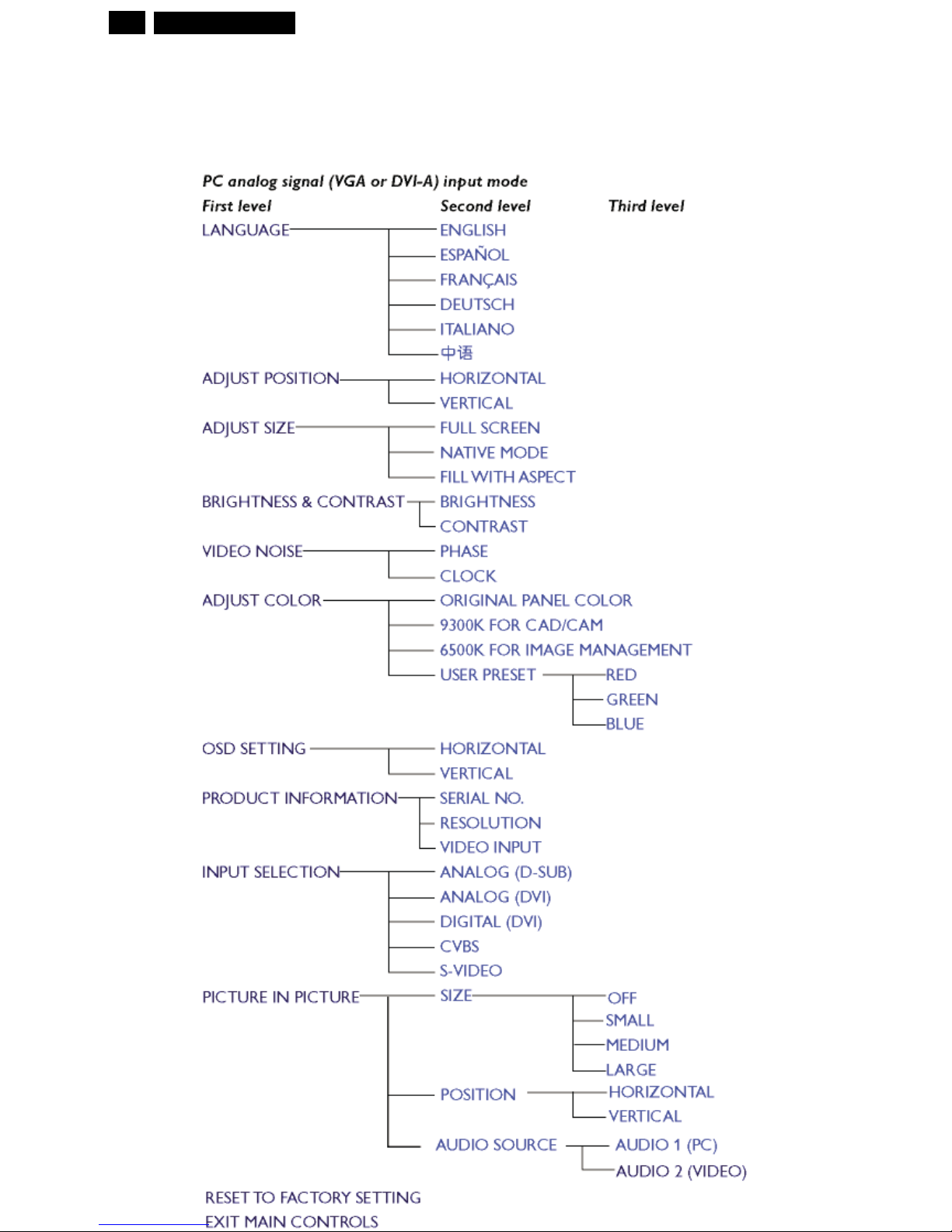
OSD menu tree -Analog
10
The OSD Tree
Below is an overall view of the structure of the On-Screen Display. You can use this as reference
when you want to later on work your way around the different adjustments.
9
Go to cover page
Hudson2 200P3
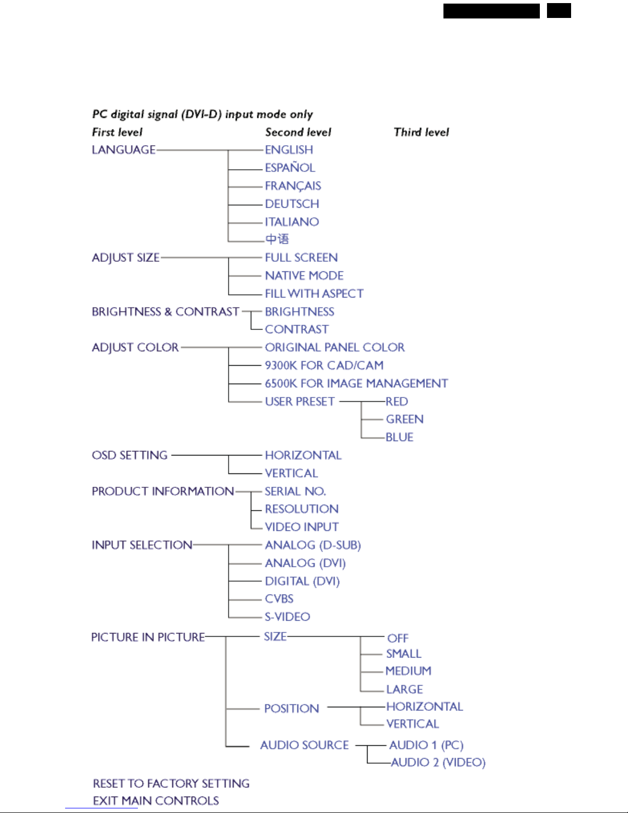
OSD menu tree - Digital
11
The OSD Tree
Below is an overall view of the structure of the On-Screen Display. You can use this as reference
when you want to later on work your way around the different adjustments.
9
Go to cover page
Hudson2 200P3
12
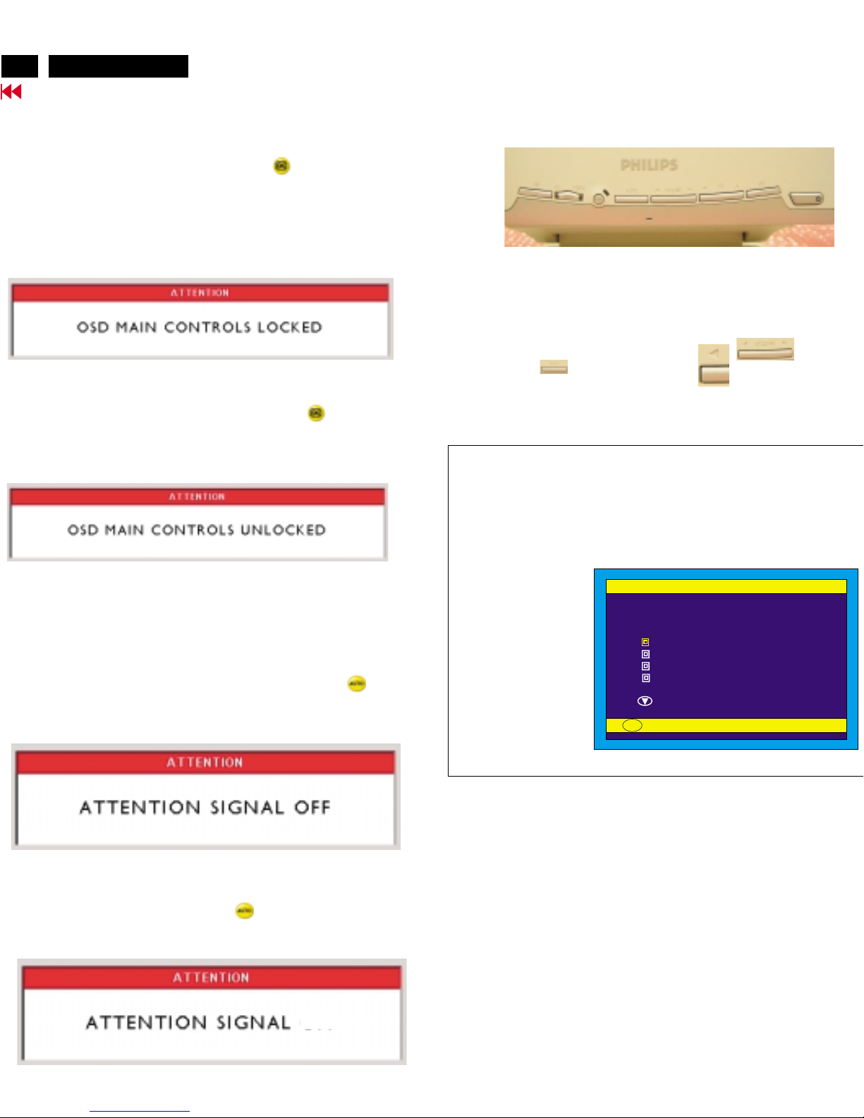
OSD Lock/Unlock, Aging Mode
Go to cover page
ATTENTION
OSD MAIN CONTROLS LOCKED
ATTENTION
OSD MAIN CONTROLS UNLOCKED
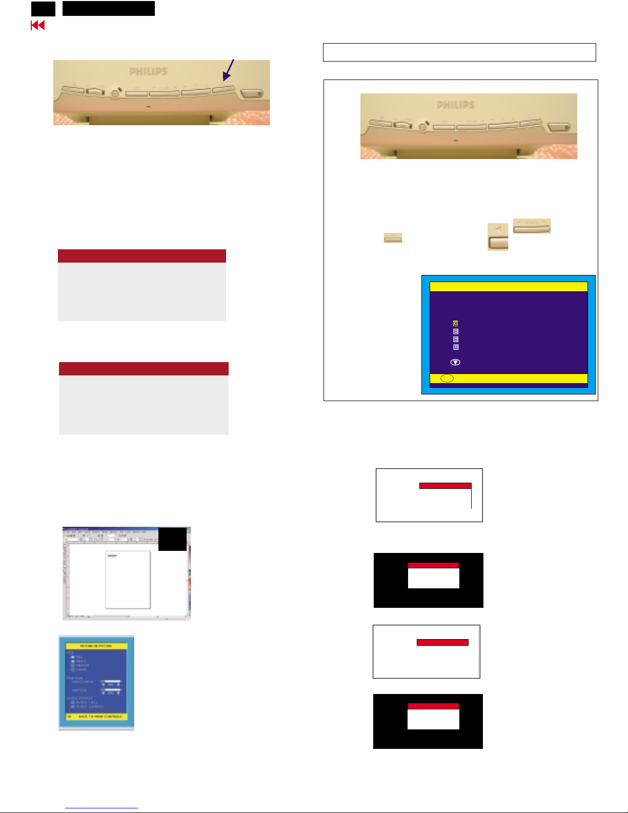
To Lock/Unlock OSD function (User Mode)
The OSD function can be locked by pressing "OK" button(1) for more
than 10 seconds, the screen shows following windows for 3 seconds.
Everytime when you press "AUTO" or "OK" button, this message
appears on the screen automatically.
Unlock OSD function:
Locked OSD function can be released by pressing"OK" button for
more than 10 seconds again.
PICTURE IN PICTURE (PIP):
Press the PIP hotkey on front control, will bring up PIP screen as
shown in Fig. 1.
Monitor (embeded software) will detect CVBS and S-Video input
for PIP function automatically at this moment.
Step 1:
Step 2:
When Factory mode comes on monitor screen, disconnect the
Signal Cable at this moment.
Access Factory Mode
Factory Mode:
How to Get into Factory Mode Menu
Turn on LCD monitor.
Push AUTO " " & Left-VOLUME" " buttons
simultaneously 3 seconds around.
Bring up Factory mode indication as shown in Fig 2.
Fig. 2
Fig. 1
---------->
AUTO
---------->
VOLUME
Factory Mode
CODE VERSION. 2.02 2002-08-07
CONFIG VERSION. 2.02 2002-08-07
OSD VERSION. 2.02 2002-08-07
ORIGINAL PANEL COLOR
9300K For CAD/CAM
6500K FOR IMAGE MANAGEMENT
AUTO COLOR ADJUST
EXIT MAIN CONTROLS
TO PROCESS ADJUSTING
OK
Factory Mode
indication===========>
Front control panel
1 = Buttons for the OSD menu (On-Screen-Display)
2 = Power indicator (PC)
3 = Power button
(OK button for OSD lock/unlock)
Fig. 1
Fig. 2
Fig. 3
Fig. 1
---------->
-------------->
---------->
------------>
---------->
AUTO
PIP
(OK)
1
2
3
Bring up
After 5 seconds, bring up :
After 5 seconds, bring up :
:
After 5 seconds, bring up :
----------
---------repeatly
Connect signal cable again => go back to normal display.
Access Aging.. Mode
A GI N G MODE.......AGI N G MODE.......
FACTORY MODE
A GI N G MODE.......AGI N G MODE.......
FACTORY MODE
A GI N G MODE.......AGI N G MODE.......
FACTORY MODE
A GI N G MODE.......AGI N G MODE.......
FACTORY MODE
<---------- PIP
Hudson2 200P3
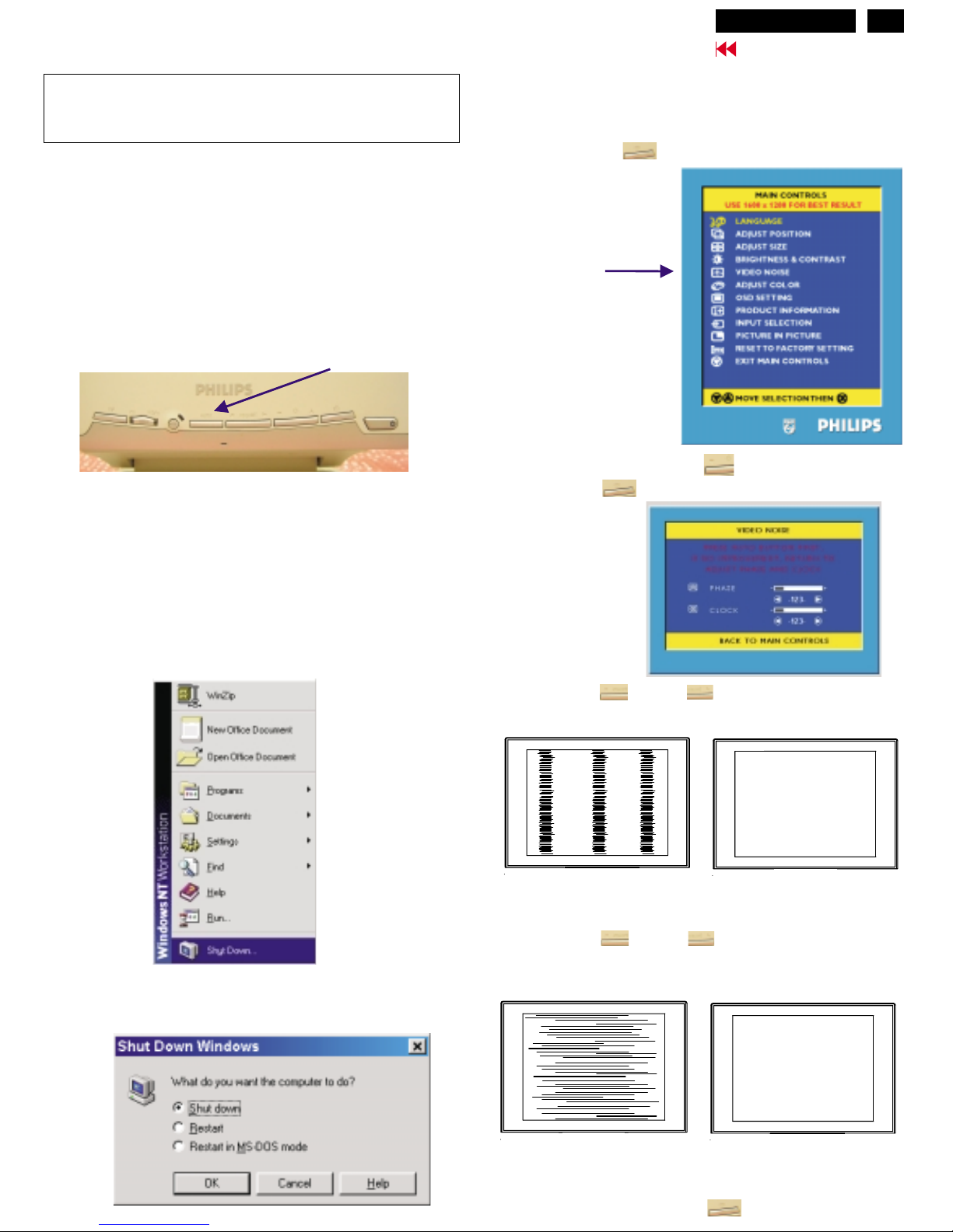
CLOCK & PHASE Adjustments
13
Go to cover page
Step 1 : Click on the Start button (Win95, Win98 or Win NT)
and choose " Shut Down...". as shown in Fig. 2.
Step 2 : The menu of " Shut Down Windows " is as shown in Fig. 3
Step 3 : Retain Shut Down Window on the screen , follow
the CLOCK and PHASE adjustment instructions for the
optimal video display.
PHASE phenomenon
Due to the different quality of video signal generated from graphics
cards. By press AUTO button for
t is necessary to adjust
CLOCK and PHASE functions for the optimal video display of LCD
monitor by manual. Following steps will guide you to make correct
adjustment of CLOCK and PHASE.
However, CLOCK and PHASE functions are only available while analog
video signal is supplied. Operating unit under digital signal state, the
video clock information can be obtained from graphics cards directly.
Therefor, it is unnecessary to adjust these functions.
CLOCK and PHASE adjustment
automatically. Sometimes, the deviation of video signal which generated
from graphics cards is out of control, then i
Manual adjustment
If the quility of display still poor or flicker, you may also improve it by
manual adjust CLOCK and PHASE functions to eliminate the flicker.
Step 4 : Press the OK button to bring up MAIN CONTROLS
(OSD menu).
Step 8 : Press Left or Right to adjust PHASE.
The picture will be adjusted as following figure, adjust PHASE
and check the picture, stop at the point that without any vertical
jitter bar remaining on the screen.
button
Step 5 : Select Video Noise by press button.
Step 6 : Press OK to bring up it s submenu.button
Step 7 : Press Left or Right to adjust CLOCK. The
picture will be adjusted as following figure, adjust CLOCK to
fine-tune the video until optimal display is obtained.
button
Step 9 : Quit OSD menu by press OK button to save the settings.
CLOCK Phenomenon
Video Noise
Using UP or DOWN
button to select it.
(Auto adjustment hotkey)
Front control panel
1 = OK button for the OSD menu (On-Screen-Display)
2 = Power indicator (PC)
3 = Power button
AUTO button
The monitor has build-in a auto adjustment hotkey on the front panel,
you may obtained a optimal video display by simply press the
button and save the settings. CLOCK, PHASE, Vertical position, and
Horizontal position are adjusted automatically.
AUTO
Fig. 1
Fig. 4
Fig. 5
Fig. 2
(Before)
(Before)
(After)
(After)
Fig. 3 (Win 98)
---------->
---------->
------------>
---------->
AUTO
OK
1
2
3
Hudson2 200P3
14
Go to cover page
DDC Instructions
General
Pin assignment
1
10
6
11
15
5
Assignment
Assignment
Pin No.
Pin No.
Ground
No Connected
Ground
Blue video input
2
7
6
8
4
5
3
1
9
12
11
14
13
15
10
Red video ground
Blue video ground
Green video ground
+5V
Ground
Data clock line(SCL)
V.Sync(VCLK for DDC)
H.Sync
Serial data line(SDA)
Green video input
Red video input
A. 15-pin D-Sub Connector
DDC Data Re-programming
Analog DDC IC, Digital DDC IC & EEPROM
Additional information
In case the DDC data memory IC or main EEPROM which storage all
factory settings were replaced due to a defect, the serial numbers have
to be re-programmed" ".
It is advised to re-soldered DDC IC and main EEPROM from the old
board onto the new board if circuit board have been replaced, in this
case the DDC data does not need to be re-programmed.
Additional information about DDC (Display Data Channel) may be
obtained from Video Electronics Standards Association (VESA).
Extended Display Identification Data(EDID) information may be also
obtained from VESA.
DDC EDID structure
For Analog interface: Standard Version 3.0
Structure Version 1.2
For Digital inferface: Standard Version 3.0
Structure Version 1.3
1. An i486 (or above) personal computer or compatible.
2. Microsoft operation system Windows 95/98.
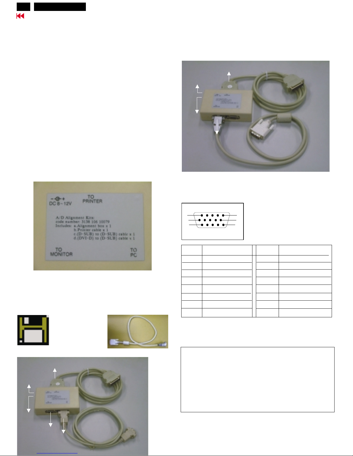
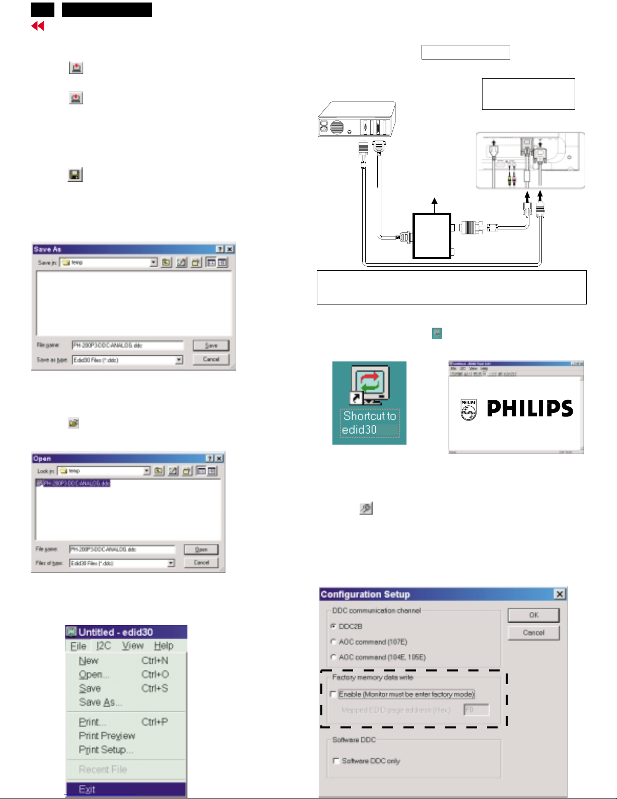
4. A/D Alignment kits (3138 106 10079):
inclusion : a. Alignment box x1 (as Fig. 2)
b. Printer cable x1
c. (D-Sub) to (D-Sub) cable x1
d. (DVI-D) to (D-Sub) cable x1 (as Fig. 3)
Note: The EDID301.EXE (Release Version 1.58 20000818)is a
windows-based program, which cannot be run in MS-DOS.
System and equipment requirements
3. EDID301.EXE program (3138 106 10103) as shown in Fig. 1
**********************************************************************************
(pos. 7601, 128 bytes data) with :
=> updated by DDC Alignment kit.
(pos. 7463, OSD data, Factory data)
(pos. 7201, 128 bytes data) with :
=> updated by DDC Alignment kit.
with :
=> updated by another tool and application software.
**********************************************************************************
Analog DDC IC serial number
EEPROM
Digital DDC IC serial number
serial number
Diskette with EDID301.EXE
EDID301.EXE
Ver:1.58
(DVI-D) to (D-Sub) cable
Note: The alignment box has already build-in a batteries socket for
using as power source. Pull out the socket by
remove four screws at the rear of box. Please do not forget that
remove batteries after programming. The energy of batteries can
only drive circuits for a short period of time.
batteries (9V)
To Monitor
DC 8V~12V
Video Card
Video Card
To Printer
Power
indicator
A/D Alignment Kits - Analog connectionA/D Alignment Kits - Analog connection
A/D Alignment Kits - Digital connectionA/D Alignment Kits - Digital connection
Fig. 2Fig. 2
Fig. 1Fig. 1
Fig. 3Fig. 3
To Monitor
(Digital port)
DC 8V~12V
To Printer
Power
indicator
Hudson2 200P3
Go to cover page
15
DDC Instructions (Continued)
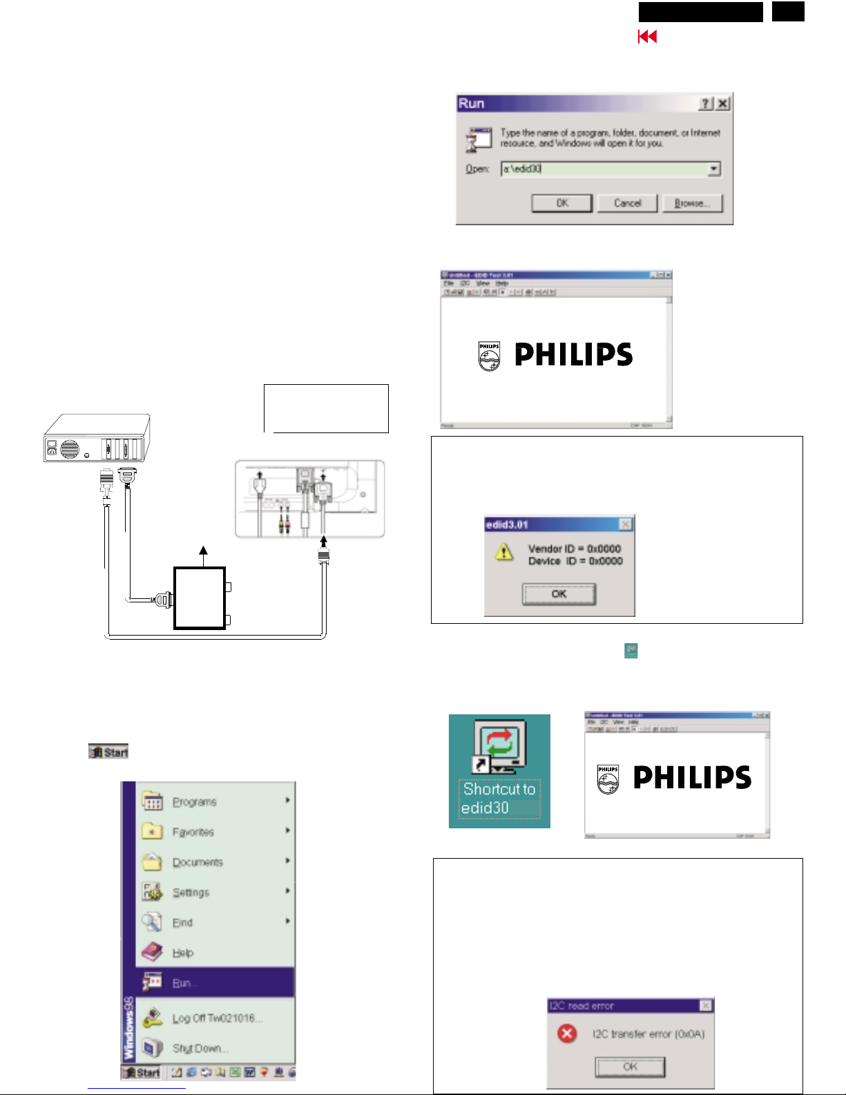
Step 3: Installation of EDID301.EXE
Method 1: Start on DDC program
Start Microsoft Windows.
1. Insert the disk containing EDID301.EXE program into floppy disk
drive.
2. Click , choose Run at start menu of Windows 95/98 as
shown in Fig. 4.
Fig. 4
4. Click button. The main menu appears (as shown in Fig. 6).OK
This is for initialize alignment box.
Fig. 6
Fig. 5
Fig. 7
Note 1: If the connection is improper, you will see the following error
message (as shown in Fig. 7) before entering the main menu.
Meanwhile, the (read EDID) function will be disable. At this time,
please make sure all cables are connected correctly and fixedly,
and the procedure has been performed properly.
3. At the submenu, type the letter of your computer's floppy disk drive
followed by :EDID301 (for example, A:\EDID301, as shown in Fig. 5).
Method 2: After create a shortcut of EDID301.EXE
This is for initialize alignment box.
: Double click EDID301 icon (as shown in Fig. 8) which is
on the screen of Windows Wallpaper.
Bring up main menu of EDID301 as shown in Fig. 9.
Fig. 9
Note 2: During the loading, EDID301 will verify the EDID data which just
loaded from monitor before proceed any further function, once
the data structure of EDID can not be recognized, the following
error message will appear on the screen as below. Please
confirm following steps to avoid this message.
1. The data structure of EDID was incorrect.
2. DDC IC that you are trying to load data is empty.
3. Wrong communication channel has set at configuration setup
windows.
4. Cables loosed or poor contact of connection.
Fig. 8
1
Configuration and procedure
There are 2 chips contained OSD string, serial number..etc
on the circuit board,
main EEPROM which storage all factory settings,OSD string.
DDC IC which storage 128byte EDID data(serial number ..etc.).
Following descirptions are the connection and procedure for Analog
and Digital DDC application, the main EEPROM can be
re-programmed along with Analog/Digital IC by enable factory memory
data write function on the DDC program (EDID301.EXE).
Initialize alignment box
In order to avoid that monitor entering power saving mode due to
sync will cut off by alignment box, it is necessary to initialize
alignment box before running programming software
(EDID301.EXE). Following steps show you the procedures and
connection.
Step 1: Supply 8~12V DC power source to the Alignment box by
plugging a DC power cord or using batteries.
Step 2: Connecting printer cable and video cable of monitor as Fig. 3
1=Power connector
2=DVI-I connector
3=D-SUB connector
Fig. 3
PC
Rear view of 200P3
~
~
To printer port (LTP1)
DC Power
8~12 V
Printer
Port
To video card
To
Monitor
To P C
1
2
3
Hudson2 200P3
16
Go to cover page
DDC Instructions (Continued)
Re-programming Analog DDC IC
Step 1: After initialize alignment box, connecting all cables and
box as shown in Fig. 10
Fig. 11
Step 2: Read DDC data from monitor
1. Click icon as shown in Fig. 11 from the tool bar to bring up
the Channels "Configuration Setup" windows as shown in Fig. 12.
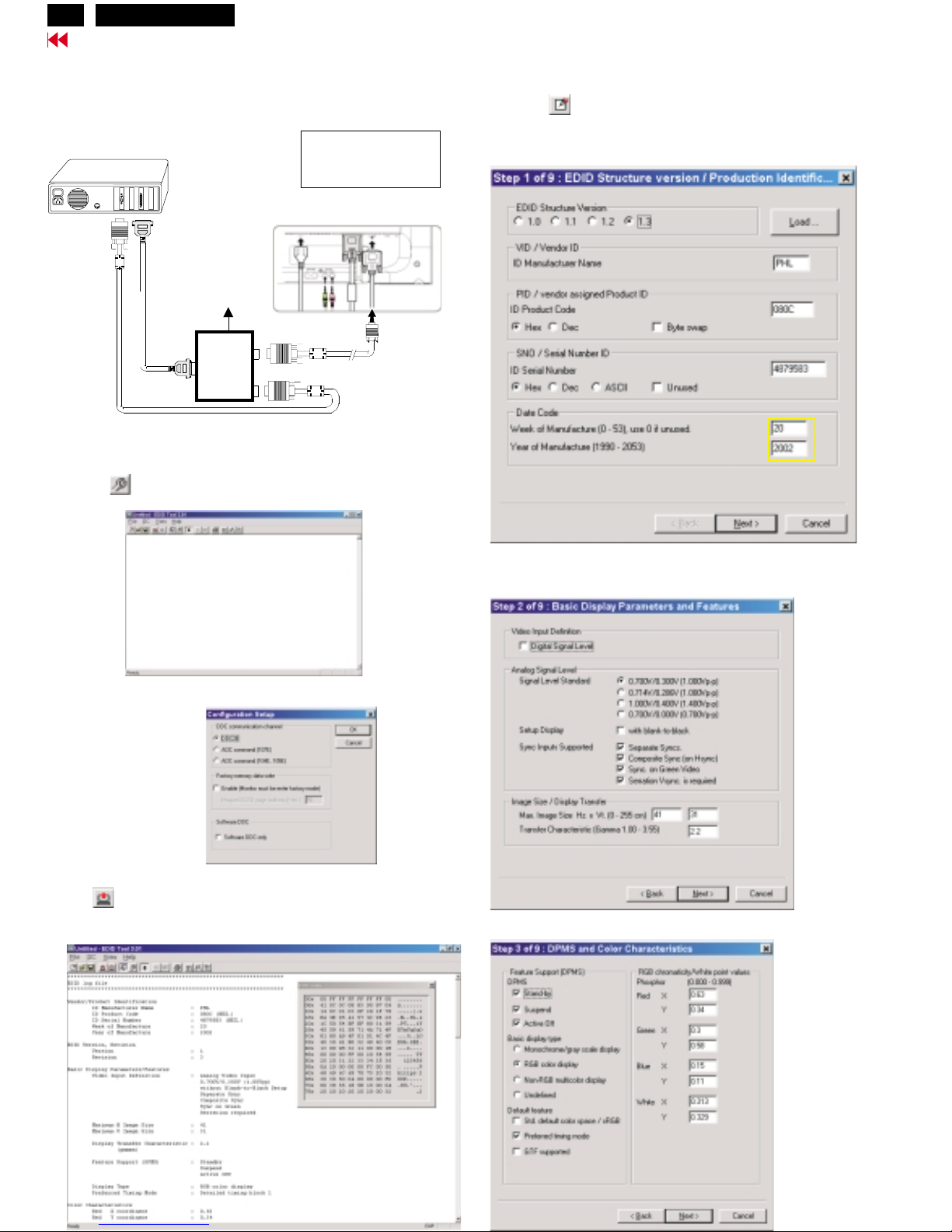
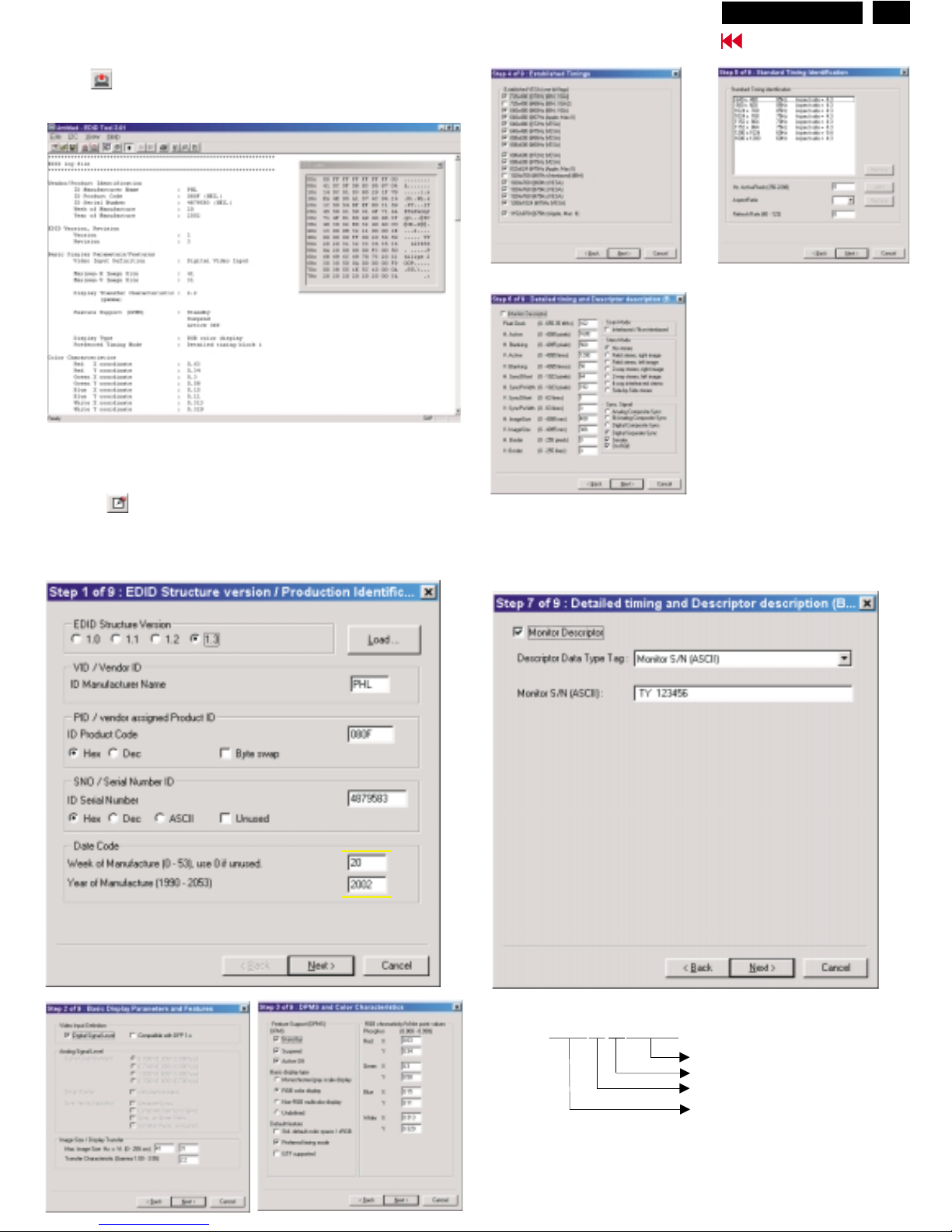
Step 3: Modify DDC data (verify EDID version, week, year)
1. Click (new function) icon from the tool bar, bring up
Step 1 of 9 as shown in Fig. 14 .
EDID301 DDC application provides the function selection and
text change (select & fill out) from Step 1 to Step 9.
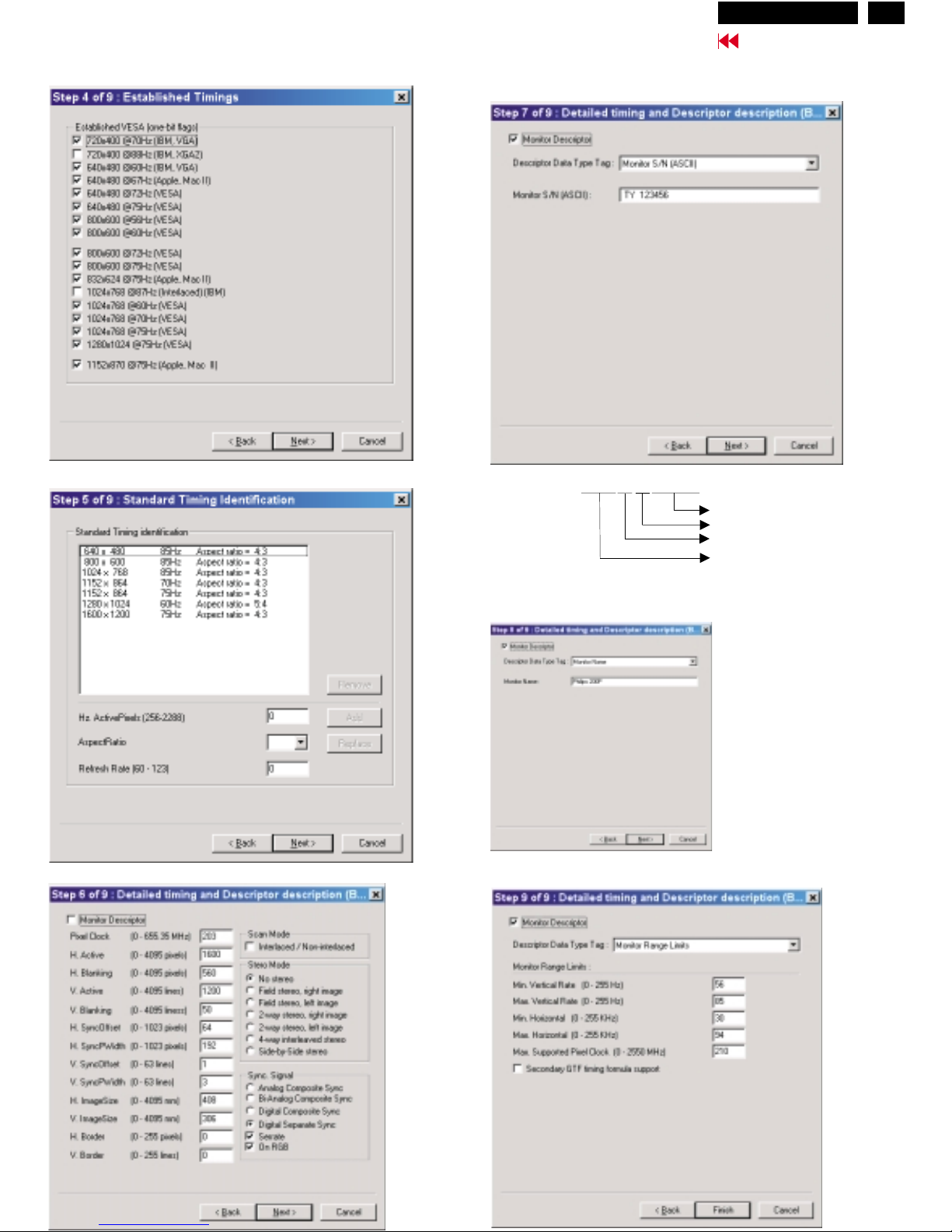
Step 4: Modify DDC data (Monitor Serial No.)
Next1. Click , bring up Fig. 15.
2. Click , bring up Fig. 16.Next
3. Click OK button to confirm your selection.
4. Click icon (Read EDID function) to read DDC EDID data from
monitor. The EDID codes will display on screen as shown in Fig. 13.
Fig. 15
Fig. 16
Fig. 12
2. Select the DDC2B as the communication channel.
(Disable "Factory memory data write")
as shown in Fig. 12.
Fig. 13
Fig. 14
Fig. 10
~
~
PC
To video card
To printer port (LTP1)
DC Power
8~12 V
Printer
Port
To
Monitor
To P C
Rear view of 200P3
1
2
3
1=Power connector
2=DVI-I connector
3=D-SUB connector
Don't close this screen. --->
<---<
-
- -
For AnalogFor Analog
select and fill out,
if necessary.
select and fill out,
if
necessary.
Hudson2 200P3
Go to cover page
17
DDC Instructions (Continued)
Fig. 17
Fig. 20
Fig. 21
Fig. 18
Fig. 19
3. Click , bring up Fig. 17.Next
6. Click , bring up Fig. 20.
(Serial number can be filled up or be changed at this moment.
Next
7. Click , bring up Fig. 21.Next
4. Click , bring up Fig. 18.Next
5. Click , bring up Fig. 19.Next
Fig. 22
8. Click , bring up Fig. 22.
- Click to exit the Step window.
Next
Finish
Definition of Serial Number (barcode format)
TY000028000001
Serial Number (U.S.A: 8 digit)
Week
Year
TY Code
TY----Chungli
CX----Dong Guan
HD----Hungary
BZ----Suzhou
(Others regions: 6 digit)
two space
(for example: change it from TY 503960
to TY 123456)
------>
Hudson2 200P3
18
Go to cover page
DDC Instructions (Continued)
Fig. 23
Fig. 24
Fig. 25
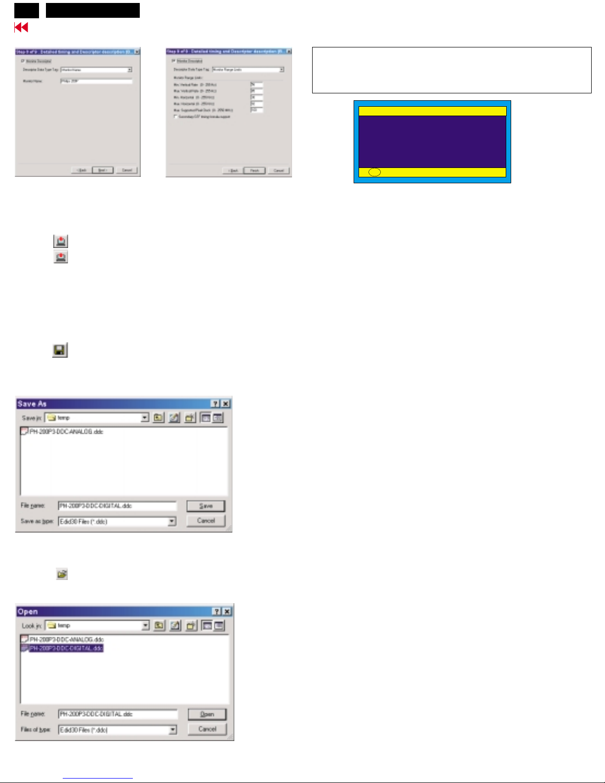
Step 7: Save DDC data
Sometimes, you may need to save DDC data as a text file for using
in other IC chip. To save DDC data, follow the steps below:
1. Click (Save) icon (or click "file"-> "save as") from the tool bar
and give a file name as shown in Fig. 23.
The file type is EDID301 file (*.ddc) which can be open in WordPad.
By using WordPad, the texts of DDC data & table (128 bytes,
hex code) can be modified. If DDC TEXTS & HEX Table are completely
correct, it can be saved as .ddc flie to re-load it into DDC IC
for DDC Data application.
Step 8: Load DDC data
Open
1. Click from the tool bar.
2. Select the file you want to open as shown in Fig. 24.
3. Click .
2. Click .Save
Step 8: Exit DDC program
Pull down the File menu and select Exit as shown in Fig. 25.
Step 6: Write DDC data
Bring up "BLACK screen" for a few seconds.
1. Click (Write EDID) icon from the tool bar to write DDC data.
2. Click (Read EDID) to re-confirm (check contents) it.
Re-programming Digital DDC IC
Connecting all cables and alignment box as shown in
Fig. 26.
Step 1:
After connection for Digital DDC application, if it is still in Analog DDC
application of EDID301.
Exit EDID301 program before Digital DDC application.
Fig. 27
Fig. 28
Step 2: Initialize alignment box
(Shortcut of EDID301.EXE on
Double click EDID301 icon (as shown in Fig. 27) which is
on the screen of Windows Wallpaper.
Bring up main menu of EDID301 as shown in Fig. 28.
Windows Wallpaper already.)
Step 3: Read DDC data from monitor
1. Click icon from the tool bar to bring up the Channels
Configuration Setup windows as shown in Fig. 28.
2. Select the DDC2B as the communication channel.
as shown in Fig. 29.
Disable "Factory memory data write" for Digital DDC
application
3. Click OK button to confirm your selection.
Fig. 29
1
1
Fig. 26
DVI
D-SUB
~
~
PC
To video card
To printer port (LTP1)
DC Power
8~12 V
To
Monitor
To P C
Printer
Port
D-Sub connector
Rear view of 200P3
1
2
3
1=Power connector
2=DVI-I connector
3=D-SUB connector
Hudson2 200P3
19
Go to cover page
DDC Instructions (Continued)
4. Click icon (Read EDID function) to read DDC EDID data from
monitor. The EDID codes will display on screen as shown in Fig. 30.
Fig. 30
Step 4: Modify DDC data (verify EDID version, week, year)
1. Click (new function) icon from the tool bar, bring up
Step 1 of 9 (Digital) as shown in Fig. 31 .
EDID301 DDC application provides the function selection and
text change (select & fill out) from Step 1 to Step 9.
Fig. 32
Fig. 33
Fig. 31
<--< - -
For DigitalFor Digital
select and fill out,
if necessary.
select and fill out,
if
necessary.
Step 5: Modify DDC data (Monitor Serial No.)
Monitor S
as shown in Fig. 37.
erial No. can be filled up or be changed (for example,
TY 123456)
Fig. 34
Fig. 35
Fig. 36
Fig. 37
Definition of Serial Number (barcode format)
TY000028000001
Serial Number (U.S.A: 8 digit)
Week
Year
TY Code
TY----Chungli
CX----Dong Guan
HD----Hungary
BZ----Suzhou
(Others regions: 6 digit)
two space
(for example: change it from TY 503960
to TY 123456)
------>
Hudson2 200P3
20
Go to cover page
DDC Instructions (Continued)
Step 6: Write DDC data
1. Click (Write EDID) icon from the tool bar to write DDC data.
2. Click (Read EDID) to re-confirm (check contents) it.
The 128bytes DDC data which had been written into DDC IC of
Digital Mode.
Fig. 40
Fig. 41
2. Click .Save
Step 9: Exit DDC program
Pull down the File menu and select Exit as shown in Fig. 25.
Step 7: Save DDC data
Sometimes, you may need to save DDC data as a text file for using
in other IC chip. To save DDC data, follow the steps below:
1. Click (Save) icon (or click "file"-> "save as") from the tool bar
and give a file name as shown in Fig. 40.
Step 8: Load DDC data
Open
1. Click from the tool bar.
2. Select the file you want to open as shown in Fig 41.
3. Click .
The display of SERIAL NO. by OSD can be change/update by
Analog Mode only.
It means "Analog Mode and Digital Mode are using same EEPROM
for display of SERIAL NO. by OSD" as shown in Fig. 42.
Fig. 42
************************************************************************
************************************************************************
Change/update the serial number which should be proceed
by another application software.
------->
----------------------------------
Click to exit the Step window as shown in Fig. 39.Finish
Fig. 38
Fig. 39
PRODUCT INFORMATION
SERIAL NO: TY 123456
RESOLUTION: 1024 X 768 / 75Hz
VIDEO INPUT: ANALOG(D-SUB)
BACK TO MAIN CONTROLS
OK
Hudson2 200P3

21
DDC Data of Digital
Go to cover page
**********************************************************************
EDID log file
**********************************************************************
Vendor/Product Identification
ID Manufacturer Name : PHL
ID Product Code : 080F (HEX.)
ID Serial Number : 4879583 (HEX.)
Week of Manufacture : 20
Year of Manufacture : 2002
EDID Version, Revision
Version : 1
Revision : 3
Basic Display Parameters/Features
Video Input Definition : Digital Video Input
Maximum H Image Size : 41
Maximum V Image Size : 31
Display Transfer Characteristic : 2.2
(gamma)
Feature Support (DPMS) : Standby
Suspend
Active Off
Display Type : RGB color display
Preferred Timing Mode : Detailed timing block 1
Color Characteristics
Red X coordinate : 0.63
Red Y coordinate : 0.34
Green X coordinate : 0.3
Green Y coordinate : 0.58
Blue X coordinate : 0.15
Blue Y coordinate : 0.11
White X coordinate : 0.313
White Y coordinate : 0.329
Established Timings
Established TimingsI:720x400@70Hz (IBM,VGA)
640 x 480 @60Hz (IBM,VGA)
640 x 480 @67Hz (Apple,Mac II)
640 x 480 @72Hz (VESA)
640 x 480 @75Hz (VESA)
800 x 600 @56Hz (VESA)
800 x 600 @60Hz (VESA)
Established Timings II : 800 x 600 @72Hz (VESA)
800 x 600 @75Hz (VESA)
832 x 624 @75Hz (Apple,Mac II)
1024 x 768 @60Hz (VESA)
1024 x 768 @70Hz (VESA)
1024 x 768 @75Hz (VESA)
1280 x 1024 @75Hz (VESA)
Manufacturer's timings : 1152 x 870 @75Hz (Apple,Mac II)
Standard Timing Identification #1
Horizontal active pixels : 640
Aspect Ratio : 4:3
Refresh Rate : 85
Standard Timing Identification #2
Horizontal active pixels : 800
Aspect Ratio : 4:3
Refresh Rate : 85
Standard Timing Identification #3
Horizontal active pixels : 1024
Aspect Ratio : 4:3
Refresh Rate : 85
Standard Timing Identification #4
Horizontal active pixels : 1024
Aspect Ratio : 4:3
Refresh Rate : 75
Standard Timing Identification #5
Horizontal active pixels : 1152
Aspect Ratio : 4:3
Refresh Rate : 70
Standard Timing Identification #6
Horizontal active pixels : 1152
Aspect Ratio : 4:3
Refresh Rate : 75
Standard Timing Identification #7
Horizontal active pixels : 1280
Aspect Ratio : 5:4
Refresh Rate : 60
Standard Timing Identification #8
Horizontal active pixels : 1600
Aspect Ratio : 4:3
Refresh Rate : 60
Detailed Timing #1
Pixel Clock (MHz) : 162
H Active (pixels) : 1600
H Blanking (pixels) : 560
V Active (lines) : 1200
V Blanking (lines) : 50
H Sync Offset (F Porch) (pixels) : 64
H Sync Pulse Width (pixels) : 192
V Sync Offset (F Porch) (lines) : 1
V Sync Pulse Width (lines) : 3
H Image Size (mm) : 408
V Image Size (mm) : 306
H Border (pixels) : 0
V Border (lines) : 0
Flags : Non_interlaced
: Normal Display, No stereo
: Digital Separate sync.
: Positive Vertical Sync.
: Positive Horizontal Sync.
Monitor Descriptor #2
Serial Number : TY 123456
Monitor Descriptor #3
Monitor Name : Philips 200P
Monitor Descriptor #4
Monitor Range Limits
Min. Vt rate Hz : 56
Max. Vt rate Hz : 85
Min. Horiz. rate kHz : 30
Max. Horiz. rate kHz : 92
Max. Supported Pixel : 160
No secondary GTF timing formula supported.
Extension Flag : 0
Check sum : 3A (HEX.)
**********************************************************************
EDID data (128 bytes)
**********************************************************************
0: 00 1: ff 2: ff 3: ff 4: ff 5: ff 6: ff 7: 00
8: 41 9: 0c 10: 0f 11: 08 12: 83 13: 95 14: 87 15: 04
16: 14 17: 0c 18: 01 19: 03 20: 80 21: 29 22: 1f 23: 78
24: ea 25: 4e 26: 95 27: a1 28: 57 29: 4c 30: 94 31: 26
32: 1c 33: 50 34: 54 35: bf 36: ef 37: 80 38: 31 39: 59
40: 45 41: 59 42: 61 43: 59 44: 61 45: 4f 46: 71 47: 4a
48: 71 49: 4f 50: 81 51: 80 52: a9 53: 40 54: 48 55: 3f
56: 40 57: 30 58: 62 59: b0 60: 32 61: 40 62: 40 63: c0
64: 13 65: 00 66: 98 67: 32 68: 11 69: 00 70: 00 71: 1e
72: 00 73: 00 74: 00 75: ff 76: 00 77: 20 78: 54 79: 59
80: 20 81: 20 82: 31 83: 32 84: 33 85: 34 86: 35 87: 36
88: 0a 89: 20 90: 00 91: 00 92: 00 93: fc 94: 00 95: 50
96: 68 97: 69 98: 6c 99: 69 100: 70 101: 73 102: 20 103: 32
104: 30 105: 30 106: 50 107: 0a 108: 00 109: 00 110: 00 111: fd
112: 00 113: 38 114: 55 115: 1e 116: 5c 117: 10 118: 00 119: 0a
120: 20 121: 20 122: 20 123: 20 124: 20 125: 20 126: 00 127: 3a
Hudson2 200P3

DDC Data of Analog
22
Go to cover page
**********************************************************************
EDID log file
**********************************************************************
Vendor/Product Identification
ID Manufacturer Name : PHL
ID Product Code : 080C (HEX.)
ID Serial Number : 4879583 (HEX.)
Week of Manufacture : 20
Year of Manufacture : 2002
EDID Version, Revision
Version : 1
Revision : 3
Basic Display Parameters/Features
Video Input Definition : Analog Video Input
0.700V/0.300V (1.00Vpp)
without Blank_to_Black Setup
Separate Sync
Composite Sync
Sync on Green
Serration required
Maximum H Image Size : 41
Maximum V Image Size : 31
Display Transfer Characteristic : 2.2
(gamma)
Feature Support (DPMS) : Standby
Suspend
Active Off
Display Type : RGB color display
Preferred Timing Mode : Detailed timing block 1
Color Characteristics
Red X coordinate : 0.63
Red Y coordinate : 0.34
Green X coordinate : 0.3
Green Y coordinate : 0.58
Blue X coordinate : 0.15
Blue Y coordinate : 0.11
White X coordinate : 0.313
White Y coordinate : 0.329
Established Timings
Established Timings I : 720 x 400 @70Hz (IBM,VGA)
640 x 480 @60Hz (IBM,VGA)
640 x 480 @67Hz (Apple,Mac II)
640 x 480 @72Hz (VESA)
640 x 480 @75Hz (VESA)
800 x 600 @56Hz (VESA)
800 x 600 @60Hz (VESA)
Established Timings II : 800 x 600 @72Hz (VESA)
800 x 600 @75Hz (VESA)
832 x 624 @75Hz (Apple,Mac II)
1024 x 768 @60Hz (VESA)
1024 x 768 @70Hz (VESA)
1024 x 768 @75Hz (VESA)
1280 x 1024 @75Hz (VESA)
Manufacturer's timings :1152 x 870 @75Hz (Apple,Mac II)
Standard Timing Identification #1
Horizontal active pixels : 640
Aspect Ratio : 4:3
Refresh Rate : 85
Standard Timing Identification #2
Horizontal active pixels : 800
Aspect Ratio : 4:3
Refresh Rate : 85
Standard Timing Identification #3
Horizontal active pixels : 1024
Aspect Ratio : 4:3
Refresh Rate : 85
Standard Timing Identification #4
Horizontal active pixels : 1152
Aspect Ratio : 4:3
Refresh Rate : 70
Standard Timing Identification #5
Horizontal active pixels : 1152
Aspect Ratio : 4:3
Refresh Rate : 75
Standard Timing Identification #6
Horizontal active pixels : 1280
Aspect Ratio : 5:4
Refresh Rate : 60
Standard Timing Identification #7
Horizontal active pixels : 1600
Aspect Ratio : 4:3
Refresh Rate : 75
Detailed Timing #1
Pixel Clock (MHz) : 203
H Active (pixels) : 1600
H Blanking (pixels) : 560
V Active (lines) : 1200
V Blanking (lines) : 50
H Sync Offset (F Porch) (pixels) : 64
H Sync Pulse Width (pixels) : 192
V Sync Offset (F Porch) (lines) : 1
V Sync Pulse Width (lines) : 3
H Image Size (mm) : 408
V Image Size (mm) : 306
H Border (pixels) : 0
V Border (lines) : 0
Flags : Non_interlaced
: Normal Display, No stereo
: Digital Separate sync.
: Positive Vertical Sync.
: Positive Horizontal Sync.
Monitor Descriptor #2
Serial Number : TY 123456
Monitor Descriptor #3
Monitor Name : Philips 200P
Monitor Descriptor #4
Monitor Range Limits
Min. Vt rate Hz : 56
Max. Vt rate Hz : 85
Min. Horiz. rate kHz : 30
Max. Horiz. rate kHz : 94
Max. Supported Pixel : 210
No secondary GTF timing formula supported.
Extension Flag : 0
Check sum : 32 (HEX.)
**********************************************************************
EDID data (128 bytes)
**********************************************************************
0: 00 1: ff 2: ff 3: ff 4: ff 5: ff 6: ff 7: 00
8: 41 9: 0c 10: 0c 11: 08 12: 83 13: 95 14: 87 15: 04
16: 14 17: 0c 18: 01 19: 03 20: 0f 21: 29 22: 1f 23: 78
24: ea 25: 4e 26: 95 27: a1 28: 57 29: 4c 30: 94 31: 26
32: 1c 33: 50 34: 54 35: bf 36: ef 37: 80 38: 31 39: 59
40: 45 41: 59 42: 61 43: 59 44: 71 45: 4a 46: 71 47: 4f
48: 81 49: 80 50: a9 51: 4f 52: 01 53: 01 54: 4c 55: 4f
56: 40 57: 30 58: 62 59: b0 60: 32 61: 40 62: 40 63: c0
64: 13 65: 00 66: 98 67: 32 68: 11 69: 00 70: 00 71: 1e
72: 00 73: 00 74: 00 75: ff 76: 00 77: 20 78: 54 79: 59
80: 20 81: 20 82: 31 83: 32 84: 33 85: 34 86: 35 87: 36
88: 0a 89: 20 90: 00 91: 00 92: 00 93: fc 94: 00 95: 50
96: 68 97: 69 98: 6c 99: 69 100: 70 101: 73 102: 20 103: 32
104: 30 105: 30 106: 50 107: 0a 108: 00 109: 00 110: 00 111: fd
112: 00 113: 38 114: 55 115: 1e 116: 5e 117: 15 118: 00 119: 0a
120: 20 121: 20 122: 20 123: 20 124: 20 125: 20 126: 00 127: 32
Hudson2 200P3
23
Go to cover page
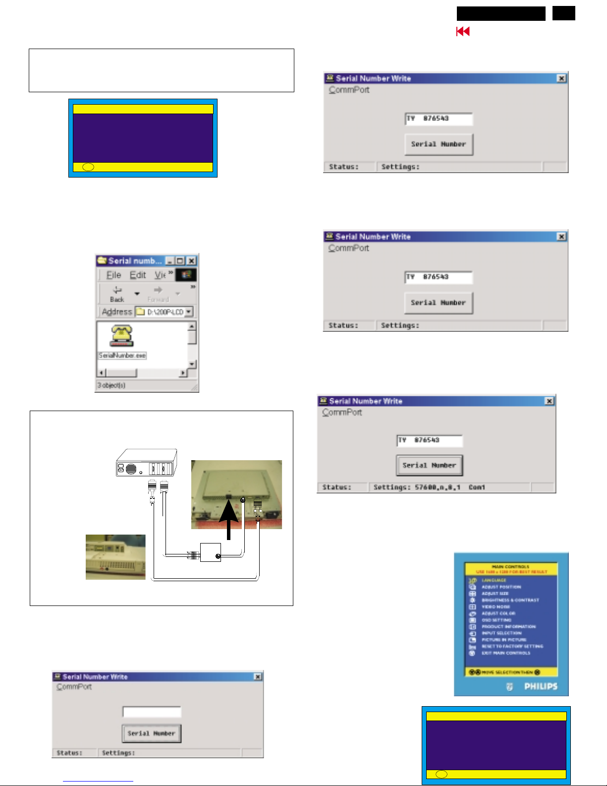
Serial number application
The display of SERIAL NO. by OSD can be change/update by
another application software only.
Analog Mode and Digital Mode are using same EEPROM(pos. 7463)
for display of SERIAL NO. by OSD" as shown in Fig. 1.
Fig. 1 (example, SERIAL NUMBER by OSD)
Step 1: Double click "SerialNumber.exe"
Bring up: Fig. 4
Step 2: Click "Serial Number" as shown in Fig. 6.
Step 3: Verify "Serial Number" by OSD as shown in Fig. 8,9.
Press OK button
=>select "PRODUCT INFORMATION"
=>press OK button
Bring up :
Fig. 9 for verification.
Fig. 2
Fig. 4
*****************************************************************************
*****************************************************************************
Change/update the serial number which should be proceed
by application software "SerialNumber.exe" as shown in Fig. 2..
------->
----------------------------------
PRODUCT INFORMATION
SERIAL NO: TY 123456
RESOLUTION: 1024 X 768 / 75Hz
VIDEO INPUT: ANALOG(D-SUB)
BACK TO MAIN CONTROLS
OK
PRODUCT INFORMATION
SERIAL NO: TY 876543
RESOLUTION: 1024 X 768 / 75Hz
VIDEO INPUT: ANALOG(D-SUB)
BACK TO MAIN CONTROLS
OK
Fill out serial number of monitor.
For example "TY 876543" as shown in Fig. 5.
Fig. 5
Fig. 6
Fig. 7
Fig. 8
Fig. 9
---------->
(two space)
(click "Serial Number")
(Com port for application)
Bring up Fig. 7 with "57600,n,8,1 Com1"
-------------------->
---------------->
---->
Fig. 3
Connection: for Serial Number application
Rear view of 200P3
PC
To Com1 or Com2 (PC)
To video card
Video cable
Com1 or
Com2
25 pins
9 pins
9 pins
Monitor
D-Sub
Connect to
Mains cord
Remove
plastic cover-->
Hudson2 200P3
24
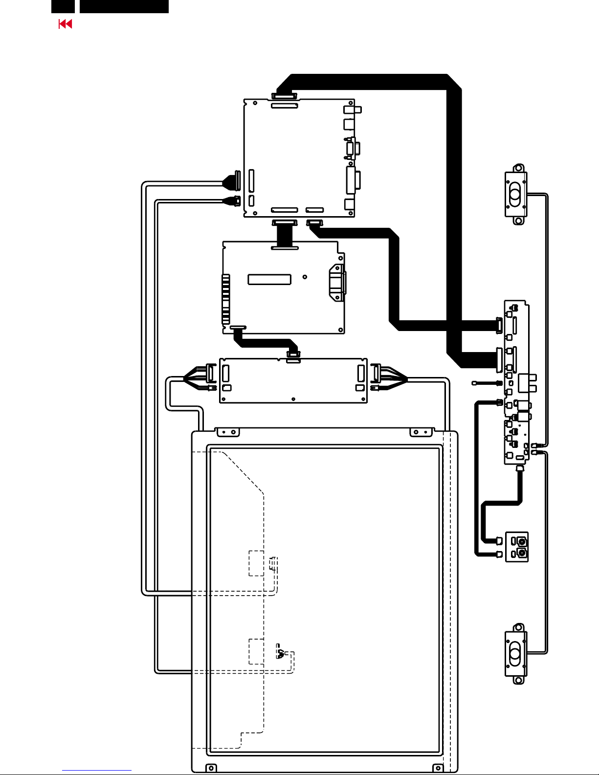
Wiring Diagram
Go to cover page
Hudson2 200P3
Model : 200P3G/00C
SCALER PCB
POWER PCB
INERTER
PCB
SPEAKER-L
SPEAKER-R
AUDIO PCB
LCD PANEL
CONTROL - AUDIO PCB
1701
8052
1711
8051
1704
1311
DVI-1
AC IN
1902
1912
1307
MIC
1903
1904
1931
1933
1905
1908
CN5
CN1
CN2
CN4
CVBS
D-SUB
S-VIDEO
1705
CN2
CN3
25
Go to cover page
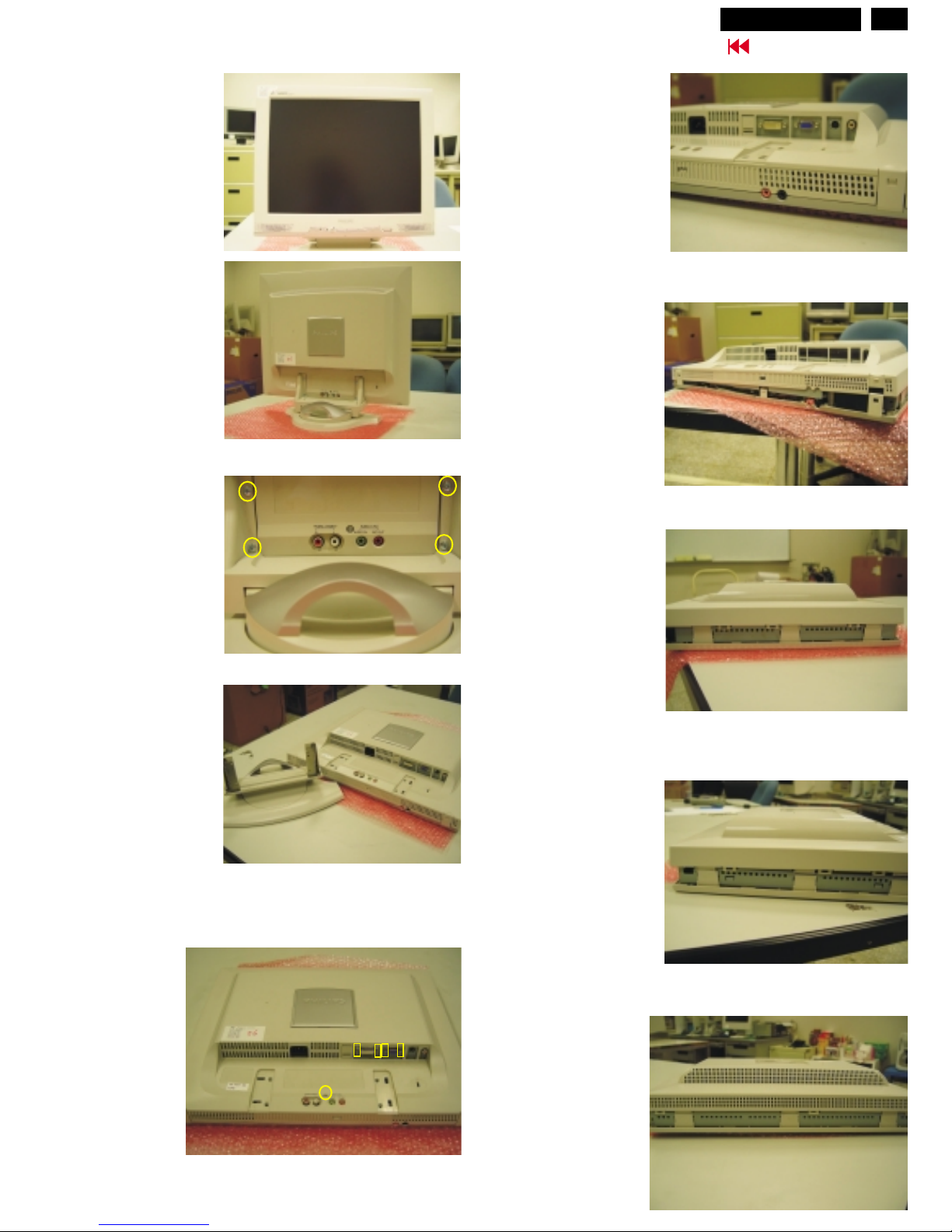
Mechanical Instructions
Front view as shown
in Fig. 1.
Rear view as shown
in Fig. 2.
Fig. 1
Fig. 2
Step 1 :
Disconnect and remove the
signal and power cables from
the back of the monitor as
shown in Fig. 2.
Fig. 3 (Before)
Step 2 :
1.
on a soft area to
prevent it from getting
scratched, defaced, or
broken.
2.Remove the 4 screws
as shown in Fig. 3.
3.Remove the monitor
base from the monitor
as shown in Fig. 4.
Lay the front bezel
down
Fig. 4 (After)
base assembly-------->
4 SCREWs
SCREW
Fig. 5
Step 3 :
1.
on a soft area
to prevent it from
getting scratched,
defaced, or broken.
2.Remove 5 screws
as shown in Fig. 5.
Lay the front bezel
down
Fig. 9 (Right side view)
Fig. 10 (Top side view)
Fig. 8 (Left side view)
Fig. 7 (Bottom side view)
Fig. 6 (Bottom side view)
Step 4 :
Turn the set over
and release all the
plastic clips (12 claws)
by plastic scew
and hands
as shown in
Fig. 6,7,8,9 & 10.
Step 5 :
Remove rear cover.
Rear cover==>
Rear cover==>
===>
===>
===>
===>
===>
===>
===>
===>
===>
===>
===>
===>
===>
===>
Plastic clips
Plastic clips
Plastic clips
Plastic clips
Plastic clips
Hudson2 200P3
26
Go to cover page
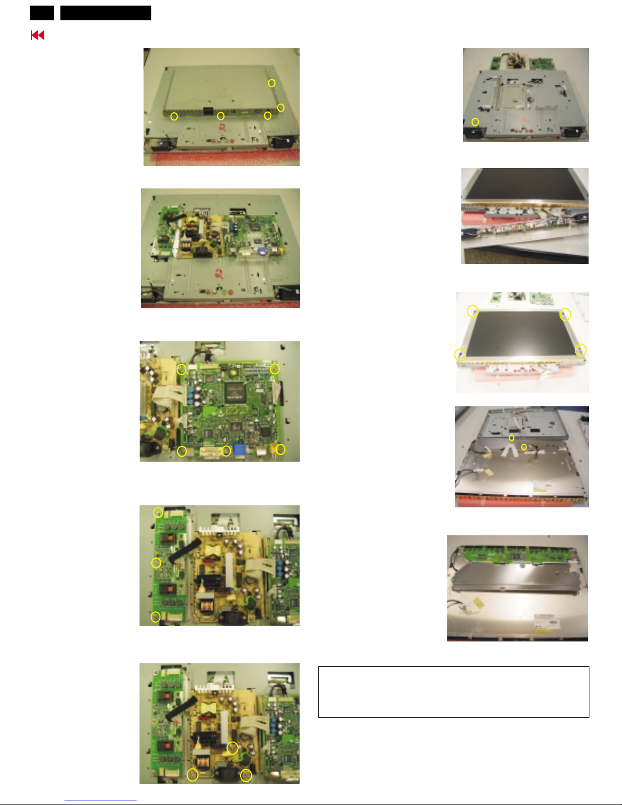
Mechanical Instructions (Continued)
Hudson2 200P3
Step 8 :
Remove 5 screws and
disconnect the connectors,
then Scaler board can be
taken out as shown
in Fig. 13.
Step 10 :
Remove 3 screws and
disconnect the connectors,
then Power board can be
taken out as shown
in Fig. 15.
Fig. 12
Fig. 13
1703
CN3
CN5
CN2
CN4
1201
1601
1632
1633
5 SCREWs
1701
1311
1705
1711
1704
10 SCREWs
metal shield
<==
<==
<=
<==
<=
Fig. 14
Fig. 15
CN1 ===========>
Step 9 :
Disconnect CN1~CN5
on inverter board and
remove 3 screws, inverter
board can be taken out
as shown in Fig. 14.
SCREWs
SCREW
*************************************************************************
In warranty, it is not allowed to disassembly the LCD panel,
even the "Backlight unit" defect.
************************************************************************
Step 14 :
Remove 4 screws
as shown in Fig. 18.
Fig. 11 (metal shield)
Fig. 12
inverter
power
scaler
Step 6 :
Remove 10 screws
as shown in Fig. 11.
Step 7 :
After removing metal shield,
inverter, power & scaler
board are as shown in
Fig. 12.
===>
===>
Step 11 :
Inverter,power & scaler
board are as shown in Fig. 16.
Step 12 :
Remove a screw
as shown in Fig. 16.
Step 13 :
Turn the "Panel with metal shield",
then remove the Front Bezel
(plastic clip)
as shown in Fig. 17.
Fig. 16
Fig. 17
Front bezel ----->
Front control board
------------->
scaler board ===>
SCREW
1912
1906
Fig. 18
Step 15 :
remove metal frame of
LCD panel as shown in
Fig. 19.
Turn the panel again,
PCB assembly of
LCD panel as shown in
Fig. 20.
Step 16 :
Remove 2 screws
as shown in
Fig. 19.
Fig. 20
Fig. 19
metal frame
LCD panel
screw
PCB assembly ----------->
27
Go to cover page
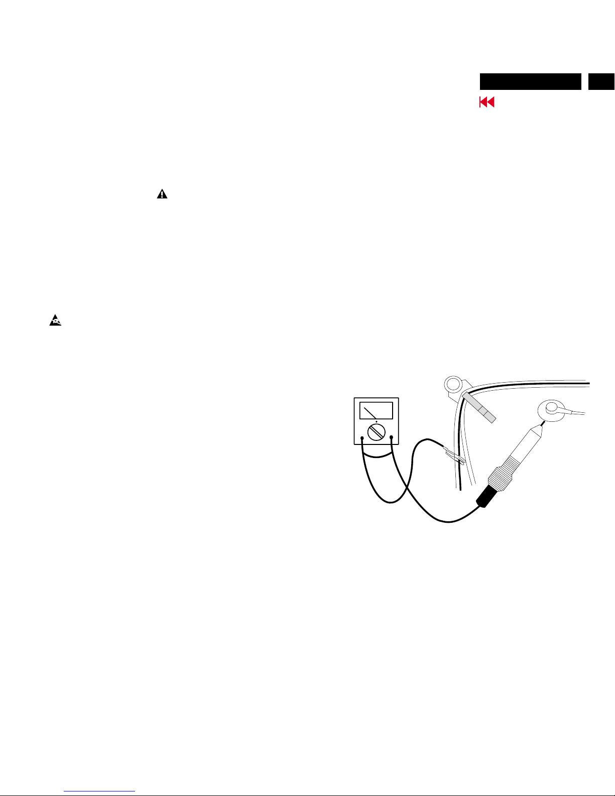
Warning and Notes
Fig.1
V
Warnings
1
2
0V
3 ESD
4
5
6
7
8
9
10.
11.
. Safety regulations require that the unit should be returned
in its original condition and that components identical to
the original components are used. The safety components
are indicated by the symbol .
. In order to prevent damage to ICs and transistors, all
high-voltage flash-overs must be avoided. In order to
prevent damage to the picture tube, the method shown
in Fig. 1 should be used to discharge the picture tube.
Use a high-voltage probe and a multimeter (position DC-V).
Discharge until the meter reading is (after approximately
30 seconds).
.
All ICs and many other semiconductors are sensitive to
electrostatic discharges (ESD). Careless handling during
repair can drastically shorten their life. Make sure that
during repair you are connected by a pulse band with
resistance to the same potential as the ground of the unit.
Keep components and tools also at this same potential.
. When repairing a unit, always connect it to the AC Power
voltage via an isolating transformer.
. Be careful when taking measurements in the high-voltage
section and on the picture tube panel.
. It is recommended that saferty goggles be worn when
replacing the picture tube.
. When making adjustments,use plastic rather than metal tools.
This will prevent any short-circuit or the danger of a
circuit becoming unstable.
. Never replace modules or other components while the
unit is switched on.
. Together with the defleciton unit, the picture tube is used
as an integrated unit. Adjustment of this unit during repair
is not recommended.
After repair, the wiring should be fastened in place with
the cable clamps.
All units that are returned for service or repair must pass
the original manufactures safety tests.
Notes
The direct voltages and waveforms are average voltages.
They have been measured using the Service test software
and under the following conditions :
- Mode : 640 * 480 (31.5kHz / 60Hz)
- Signal pattern : grey scale
- Adjust brightness and contrast control for the
mechanical mid-position (click position)
The picture tube panel has printed spark gaps.
Each spark gap is connected between an electrode of the
picture tube and the Aquadag coating.
The semiconductors indicated in the circuit diagram(s)
and in the parts lists are completely interchangeable per
position with the semiconductors in the unit, irrespective
of the type indication on these semiconductors.
1.
2.
3.
(CRT ONLY)
Hudson2 200P3
28
Go to cover page
Electrical Instructions
0. General
With normal VGA card:
AC/DC Measurement:
When carry-out the electrical settings in many cases a video signal
must be applied to the monitor. A computer with :
- ATI VGA 1024 V6-1.04/PH BETA4 interface card
- PGA 1024 (4822 212 30916), Mach 8.
- PGA 1280 (4822 212 30917), Mach 32.
- ATI GPT-1600 (4822 397 10065), Mach 64 (up to 107kHz)
are used as the video signal source. The signal patterns are
selected from the "service test software" package, see user
guide 4822 727 19896 (ATI1024),
or 4822 727 20273 (PGA 1280), or
4822 727 21046 (GPT-1600).
0.1
If not using the ATI card during repair or alignment, The service
engineer also can use this service test software adapting with
normal standard VGA adaptor and using standard VGA mode
640 x 480, 31.5 kHz/60 Hz (only) as signal source.
0.2
The measurements for AC waveform and DC figure is based on
640 x 480 31.5 kHz/60 Hz resolution mode with test pattern
"16 gray scale".
Power input: 110V AC
General points
1.1 During the test and measuring, supply a distortion free AC mains
voltage to the apparatus via an isolated transformer with low
internal resistance.
1.2 All measurements mentioned hereafter are carried out at a normal
mains voltage (90 - 132 VAC for USA version, 195 -264 VAC for
EUROPEAN version, or 90 - 264 VAC for the model with full range
power supply, unless otherwise stated.)
1.3 All voltages are to be measured or applied with respect to ground,
unless otherwise stated.
Note: don't use heat-sink as ground.
1.4 The test has to be done on a complete set including LCD panel
in a room with temperature of 25 +/- 5 degree C.
1.5 All values mentioned in these test instruction are only applicable
of a well aligned apparatus, with correct signal.
1.6 The letters symbols (B) and (S) placed behind the test instruction
denotes
(B): carried out 100% inspection at assembly line
(S): carried out test by sampling
1.7 The white balance (color temperature), has to be tested in subdued
lighted room.
1.8 Repetitive power on/off cycle are allowed.
(1) Factory Preset Modes (19 modes)
2.2 Input signal mode
2.
Signal type
2.1.1 Analog Video : 0.7 Vp-p linear, positive polarity
Sync. : TTL level, separate, positive or negative polarity
Signal source: pattern generator format as attachment.
(table 1 to 47) Reference generator : QuantumData 802G
2.1.2 Digital Video :600mVp-p TMDS Signal
2.1.3 CVBS Video :1Vp-p,75 Ohm
2.1.4 S-Video :Y-1Vp-p,75 Ohm
C-0.3Vp-p,75 Ohm
2.1.5 Audio Signal : For S-terminal L/R audio input
PC line in
Microphone in
Input signal
Item H.Freq.
(KHz)
Mode Resolution V.Freq.
(Hz)
1 31.469 IBM VGA 10H 640x350 70.086
2 31.469 IBM VGA 3H 720x400 70.087
3 31.469 IBM VGA 12H 640x480 59.940
4 35.000 MACINTOSH 640x480 67.000
5 37.500 VESA 640x480 75.000
6 35.156 VESA 800x600 56.250
7 37.879 VESA 800x600 60.317
8 46.875 VESA 800x600 75.000
9 49.700 MACINTOSH 832x624 75.000
10 48.363 VESA 1024x768 60.004
11
60.023 VESA
1024x768
75.029
12
68.700 MACINTOS
H
1152x870
75.000
13
71.810 SUN WS
1152x900
76.150
14
63.981 VESA
1280x1024
60.020
15
79.976 VESA
1280x1024
75.025
16
91.1 VESA
1280x1024
85
17
75.0 VESA
1600x1200
60
18
93.8 VESA
1600x1200
75
19
31.250 TV-PAL
688x556
50.
(2) Preset Modes (47 modes)
Item
H.Freq.
(KHz)
Mode
Resolution
V.Freq.
(Hz)
Item
H.Freq.
(KHz)
Mode Resolution
V.Freq.
(Hz)
1
31.469 IBM VGA 10H
640x350 70.086 26
71.810
SUN WS
1152x900
76.150
2
31.469 IBM
VGA 3H
720x400 70.087 27
59.673
SUN WS
1280x768
72.000
3
31.469 IBM VGA 12H
640x480 59.940 28
60.000
VESA 1280x960
60.000
4
35.000
MACINTOSH
640x480 67.000 29
75.000
VESA
1280x960
75.000
5
37.861
VESA
640x480 72.809 30
85.939
VESA 1280x960
85.002
6
37.
500
VESA
640x480 75.000 31
63.981
VESA
1280x1024
60.020
7
43.269 VESA
640x480 85.008 32
71.691
SUN WS
1280x1024
67.189
8
35.156
VESA
800x600 56.250 33
76.000 DOS/V 1280x1024
72.000
9
37.879 VESA
800x600 60.317 34
79.976
VESA
1280x1024
75.025
10
48.077
VESA
800x600 72.188 35
81.130 SUN WS
1280x1024
76.110
11
46.875
VESA
800x600 75.000 36
91.1
VESA
1280x1024
85
12
53.674 VESA
800x600 85.061 37
80.000
MACINTOSH
1360x1024
75.000
13
49.700
MACINTOSH
832x624 75.000 38
70.794
SUN WS
1440x900
76.000
14
81.1
SUN WS
960x680 112.000 39
78.66
SUN WS
1600x1000
76.000
15
48.363
VESA
1024x768 60.004 40
68.31 SUN WS
1600x1000
66.000
16
56.476
VESA
1024x768 70.069 41
84.000
MACINTOSH
1600x1200
69.000
17
60.023 VESA
1024x768 75.029 42
80.000 DOS/V 1600x1200
60.000
18
61.080 IBM XGA-2
1024x768 75.781 43
75.0
VESA 1600x1200
60
19
68.677
VESA
1024x768 84.997 44
81.3
VESA
1600x1200
65
20
68.820 SUN WS
1024x768 87.000 45
87.5
VESA
1600x1200
70
21
54.1
1152x864 60 46
93.8
VESA 1600x1200
75
22
63.851
VESA
1152x864 70.012 47
31.250
TV-PAL
688x556
50
23
67.500 VESA
1152x864 75.000
24
68.700
MACINTOSH
1152x870 75.000
25
61.845 SUN WS
1152x900 66.004
Hudson2 200P3
29
Go to cover page
Electrical Instructions (Continued)
Hudson2 200P3
3. AC, DC Adaptor
3.1 Setup the AC I/P at 90VAC, and Output DC loading at 3.33Amp,
The DC output voltage is 18.0 0.9 V DC, Adjusting is no need.
3.2 DC setting
3.01 Detach 8052 to the scaler board before testing the function.
3.02 Apply 1.2Amp 18V DC voltage to 1105. (B)
3.03 Connect inverter board to 8051 (B)
3.04 Check voltage at C2067 should be within the range 5V +/- 0.2V
(B)
3.05 Check voltage at C2077 should be within the range 3.3V +/- 0.15V
(B)
4. Display Adjustment
4.1Input signals check
In factory mode, use 64 gray level and set the R,G,B gain to 100%.
4.2 Display quality test
Use timing mode as describe in 2.2, and use the pixel on / off
pattern to adjust the clock until no stripe and adjust the phase
until clear picture.
Check all pre-setting 19 modes.
4.2.1 SOG mode test : Use following timing for SOG test
64 KHz/60Hz, 1280 X 1024, pixel=108 MHz
Horizontal
Vertical
Frame border= 0 Frame border= 0
Total size = 15.620ms Total size = 16.670 ms
Display size = 11.852ms Display size = 16.000 ms
Rear porch = 2.000ms Rear porch = 0.580 ms
Sync width = 1.000ms Sync width = 0.080 ms
Sync polarity = - Sync polarity = -
Sync on green
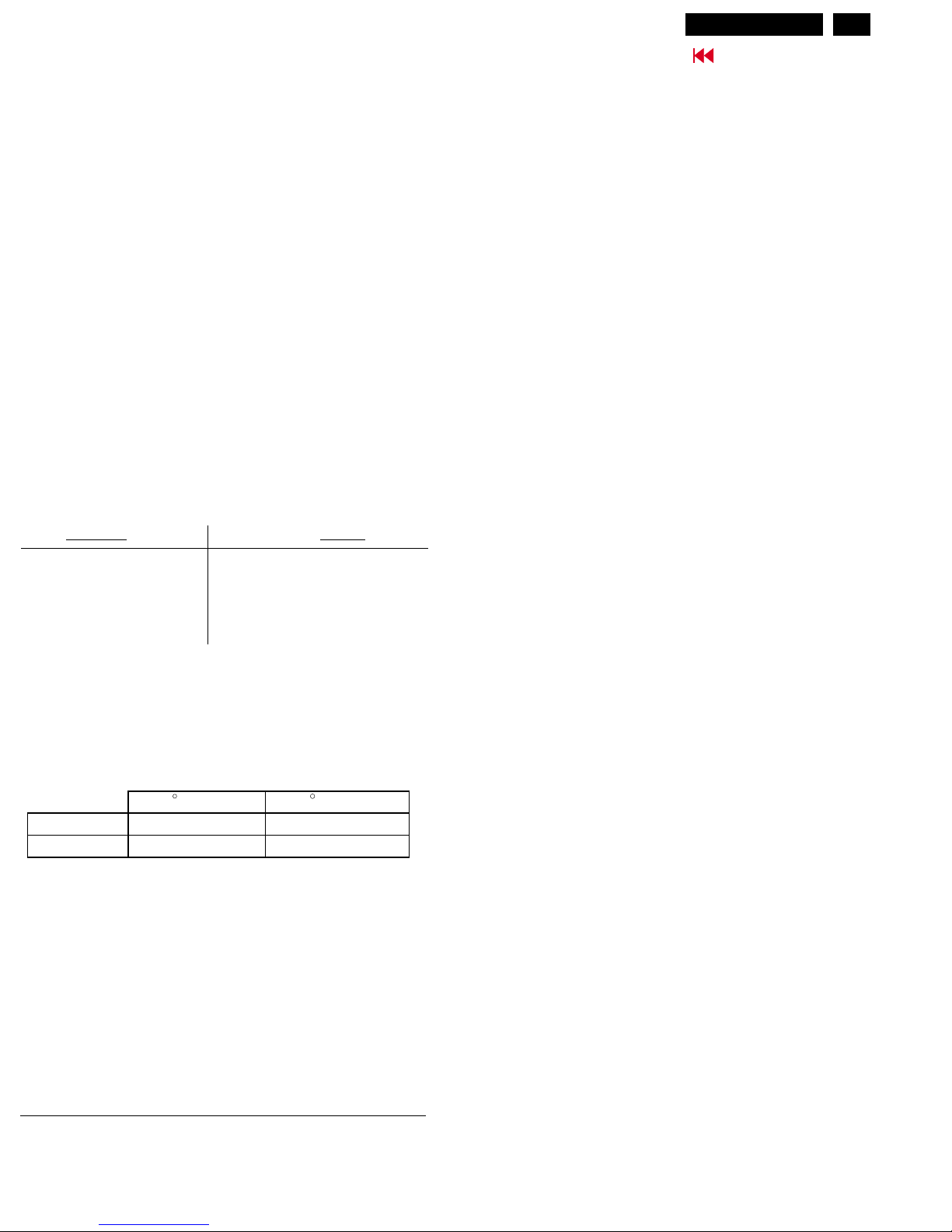
4.3 Check of WHITE-D (B)
Apply a 1280*1024 / 60Hz signal with gray 64 pattern, set brightness
control at 100%, and contrast control at 50%. Adjust the R,G,B sub_gain,
for the screen center,
the 1931 CIE chromaticity (X, Y) co-ordinates shall be;
Use Minolta CA-110 for color coordinates and luminance check.
Luminance : 200 Nits in the center of the screen when brightness at
100% and contrast set to 100%.
4.4 Check the digital interface
Check the 64 gray level color poor & noise condition.
Please refer to General Product Specification for timing table 1~47.
TIMING FOR HUDSON 200P 20" TFT UXGA COLOR LCD MONITOR
(VESA monitor timing standard Version 1.0 Release 0.7)
REFERENCE PATTERN GENERATOR : QuantumData 802G
9300 K 6500 K
x (center) 0. 281 0.015
0.015
0.015
0.312
y (center) 0.311 0.015 0.338
5.
5.1.1 PIN ASSIGNMENT OF INVERTER & WAFER 8051
PIN No. SIGNAL (INVERTER BOARD)
1 backlight power (18V)
2 backlight power (18V)
3 backlight power (18V)
4 backlight GND
5 backlight GND
6 backlight GND
7 backlight brightness ; 3.3V :8.0mA 0.5mA
0V :3.0mA 0.4mA
8 backlight ;ON/OFF control :ON>2V,OFF<1V
PIN No. SIGNAL (WAFER 8051)
1 backlight power (18V)
2 backlight power (18V)
3 backlight power (18V)
4 backlight GND
5 backlight GND
6 backlight GND
7 backlight brightness ; 3.3V :8.0mA 0.5mA
0V :3.0mA 0.4mA
8 backlight ;ON/OFF control :ON>2V,OFF<1V
5.1.2 PIN ASSIGNMENT OF WAFER 8052
PIN No. SIGNAL (WAFER 8052)
1 LIGHT_BRI_CTL
2 LIGHT_PWR_CTL
3 GND
4 DC_SW
5 +3.3V
6 GND
7 +3.3V
8 GND
9 +5V
10 +5V
11 GND
12 GND
13 +18V
14 +18V
15 GND
16 GND
PIN ASSIGNMENT OF VARIOUS WAFERS
30
Go to cover page
Electrical Instructions (Continued)
5.1.3 PIN ASSIGNMENT OF WAFER TO CONTROL BOARD
PIN No. SIGNAL (WAFER 1701)
1 OSD
2UP
3 DOWN
4 RIGHT
5 LEFT
6 AUTO
7 PIP
8 SOURCE
9 DCSW1
10 MUTEIN
11 GND
12 POWER LED
13 SLEEP LED
14 PC LED
15 VIDEO LED
16 GND
5.1.4 PIN ASSIGNMENT OF WAFER TO CONTROL BOARD
PIN No. SIGNAL (WAFER 1704)
1 +18V
2 +18V
3 GND
4 GND
5 AUDIOMUX
6 AUDIOPW
7 VOLUME
8 MUTEOUT
9 DCSW2
10 GND
5.1.5 PIN ASSIGNMENT OF WAFER TO PANE
PIN No. SIGNAL (WAFER 1705)
1 GND
2 GND
3 LCM18V
4 LCM18V
5 GND
6 GND
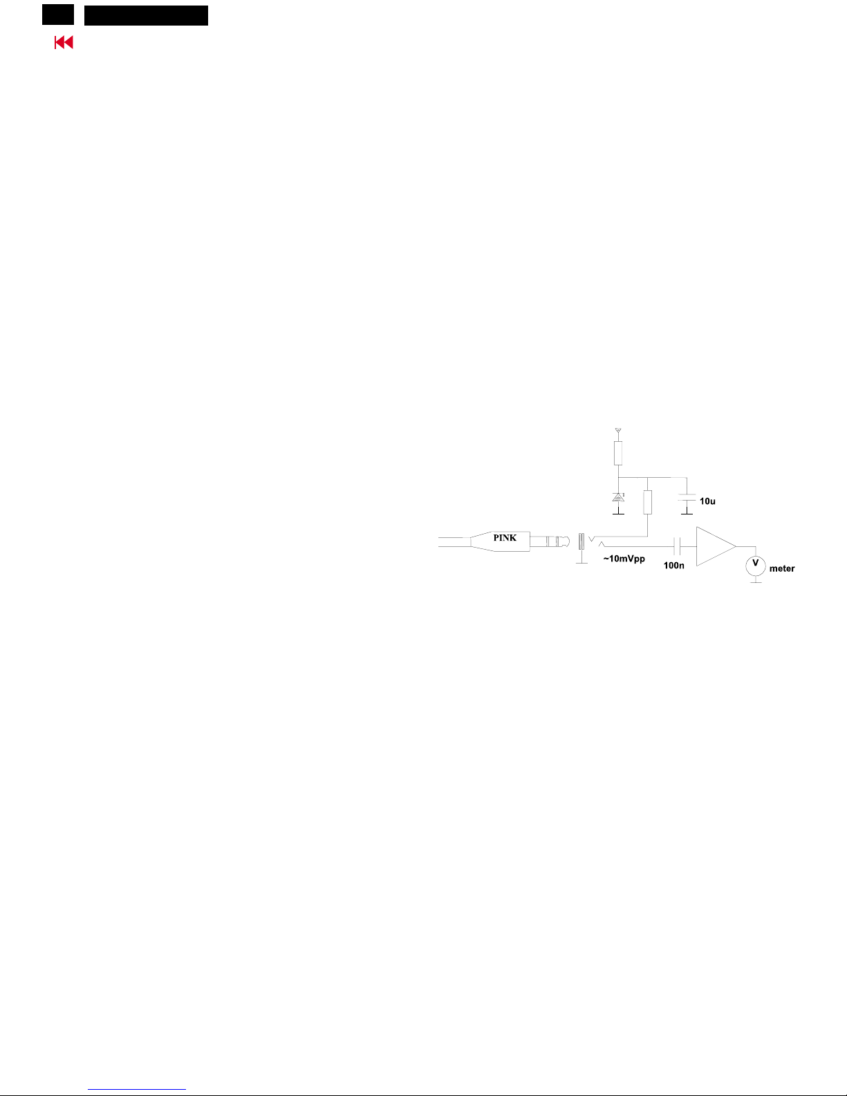
6. Microphone test (B)
The aim of the set-up below is to test whether the microphone is
operating correctly.
Connect the microphone pink plug to a signal measuring equipment
with incorporate DC bias according circuit below:
Place a reference sine wave sound source close to the microphone
openings and check the microphone output for correct output signal.
Please note that the microphone has two openings: One at front and
one at the bottom. The reference sound source should be positioned
in such a way that the sound reaches both openings.
The actual quality of microphone can only be checked by recording and
listening tests, using PC software like Microsoft Sound Recorder
(available in Windows'98/95 Multimedia menu )
+5V
220
Microphone
Test Circuit
2V4
1K
Hudson2 200P3
 Loading...