

Philips HTS-9800-W Service manual
DVD Receiver
CLASS 1
LASER PRODUCT
HTS9800W/12/37/55
1 Technical Specifications and Connection
Facilities 2
2 Measurements Setup, Service Aid &
Lead Free Requirements 5
3 Directions for use 10
4 Dismantling Instructions & Service Positions 14
5 Service Test Program 20
6 Block Diagram, Wiring Diagram 23
Block Diagram 23
Wiring Diagram 25
7 Circuit Diagram and PWB Layout 27
DVM 7.3 AV Board: Schematic 27
DVM 7.3 AV Board: Layout (Top View) 34
DVM 7.3 AV Board: Layout (Bottom View) 35
Front Display: Schematic 36
Front Display: Layout (Top View) 38
Front Display: Layout (Bottom View) 39
Front LED Panel: Schematic 40
Front LED Panel: Layout (Top View) 41
Front LED Top: Schematic 42
Front LED Top: Layout (Top View) 42
Front LED Top: Layout (Bottom View) 42
Front LED Bottom: Schematic 43
Front LED Bottom: Layout (Top View) 43
Front LED Bottom: Layout (Bottom View) 43
Interface Board: Schematic 44
Interface Board: Layout (Top View) 46
©
Copyright 2005 Philips Consumer Electronics B.V. Eindhoven, The Netherlands.
All rights reserved. No part of this publication may be reproduced, stored in
a retrieval system or transmitted, in any form or by any means, electronic,
mechanical, photocopying, or otherwise without the prior permission of Philips.
Contents PageContents Page
Interface Board: Layout (Bottom View) 47
Mains Board: Schematic 48
Mains Board: Layout 49
Wireless Interface Board: Schematic 50
Wireless Interface Board: Layout (Top View) 53
Wireless Interface Board: Layout (Bottom View) 54
PCBA SOC: Schematic 55
PCBA SOC: Layout (Top View) 55
Spk Panel: Schematic 56
Spk Panel: Layout (Top View) 57
Spk Panel: Layout (Bottom View) 58
Junction Box: Schematic 59
Junction Box: Layout (Top View) 60
Junction Box: Layout (Bottom View) 61
UCD Module Dev. Schematic 62
UCD Module Dev. Layout (Top View) 64
UCD Module Dev. Layout (Bottom View) 65
VGA Conn Board Schematic & Layout 66
8 PSU - Main Unit and Wireless Box Surround 67
PSU - Main Unit (For Information Only) 68
PSU - Wireless Box Surround 69
9 Exploded View & Spare Parts List 70
Exploded View of the Main Unit Set 70
Exploded View of the Wireless Surround Box Set 71
Exploded View of the Power Box Set 72
Spare Parts List 75
Published by TE 0608 AV Systems Printed in the Netherlands Subject to modification EN 3139 785 31510
Version 1.0
EN 2
3139 785 31510
1.
Technical Specifications and Connection Facilities
LOCATION OF PC BOARDS
JUNCTION BOX
FRONT VIEW
FRONT LED TOP
FRONT LED BOTTO
M
DISPLAY
TO
UCH PANEL
REAR VIEW
MPEG
TUNER
PSU
AMPLIFIER
AMPLIFIER
WIRELESS RECEIVER
INTERFACE
PSU
A
V WIRELESS RECEIVER BOX
EN 3
3139 785 31510
Technical Specifications and Connection Facilities
1.
VERSION VARIATIONS:
HTS9800W/12 HTS9800W/37,/55
Video (Yellow, Cinch) -
x
Component Video, (Y/Pb/Pr) -P-scan x
x
SCART (CVBS/RGB) x
-
Digital In - Coaxial x
x
TV In (Left/Right) x
x
Auxiliary (Left/Right) x
x
HDMI x
x
Power / Amp(VGA) x x
WIRELESS
TRANSMITTER
VGA
PSU
MAINS
SOCKET
SPEAKERS
CONNECTORS
INTERFACE
AMPLIFIER
AMPLIFIER
POWER BOX

EN 4
3139 785 31510
1.
Technical Specifications and Connection Facilities
1. Specifications
1.1 General:
Mains voltage : 230V for /12
110V-240V for /37,/55
Mains frequency : 50/60Hz for /37,/55
50Hz for /12
Power consumption : < 80W at 1/8 P
rated
Dimension main unit : 273 x 284 x 144mm
1.2 Tuner
FM
Tuning range : 87.5-108MHz
Grid : 50kHz
IF frequency : 10.7MHz ± 25kHz
Aerial input : 75Ω coaxial
Sensitivity at 26dB S/N : < 7µV
Selectivity at 59/300kHz bandwidth : > 25dB
IF rejection : > 60dB
Image rejection : > 25dB
Distortion at RF=1mV, dev. 75kHz : < 3%
-3dB Limiting point : 8µV
Crosstalk at RF=1mV, dev. 67.5kHz : > 28dB
1.3 AMPLIFIER:
Total output power : 6600W PMPO
550W RMS
L/R output power : 1 x 46W type: 50W
Centre : 1 x 95W type: 100W
Surround : 1 x 46W type: 50W
Subwoofer : 1 x 95W type: 100W
Frequency response ±3dB : 150Hz-20kHz
Hum (Volume Minimum) : 200nW
Residual noise (Volume Minimum) : 40nW
Input sensitivity
Aux In : 1V ± 3dB at 39kΩ
Scart In : 1V ± 3dB at 39kΩ
1.4 COMPACT DISC/VCD/DVD:
Video Decoding : MPEG-1/MPEG-2/
MPEG-4/DivX 3.11,
4.x, 5.x & 6.0/XviD
Video DAC : 12 Bits
Signal System : PAL / NTSC
Video Format : 4:3 / 16:9
CVBS Out
1)
CVBS level : 1.0 ± 0.1V
p-p
Luminance S/N : >= 55dB
RGB/YUV Out 1)
Amplitude : 0.7 ± 0.1V
p-p
S/N : >= 60dB
S-Video Out 1)
Y level : 1.0 ± 0.1V
p-p
Y S/N : >= 55dB
1)
Output terminals to be terminated with 75Ω
EN 5
3139 785 31510
Measurements Setup, Service Aid & Lead Free Requirements
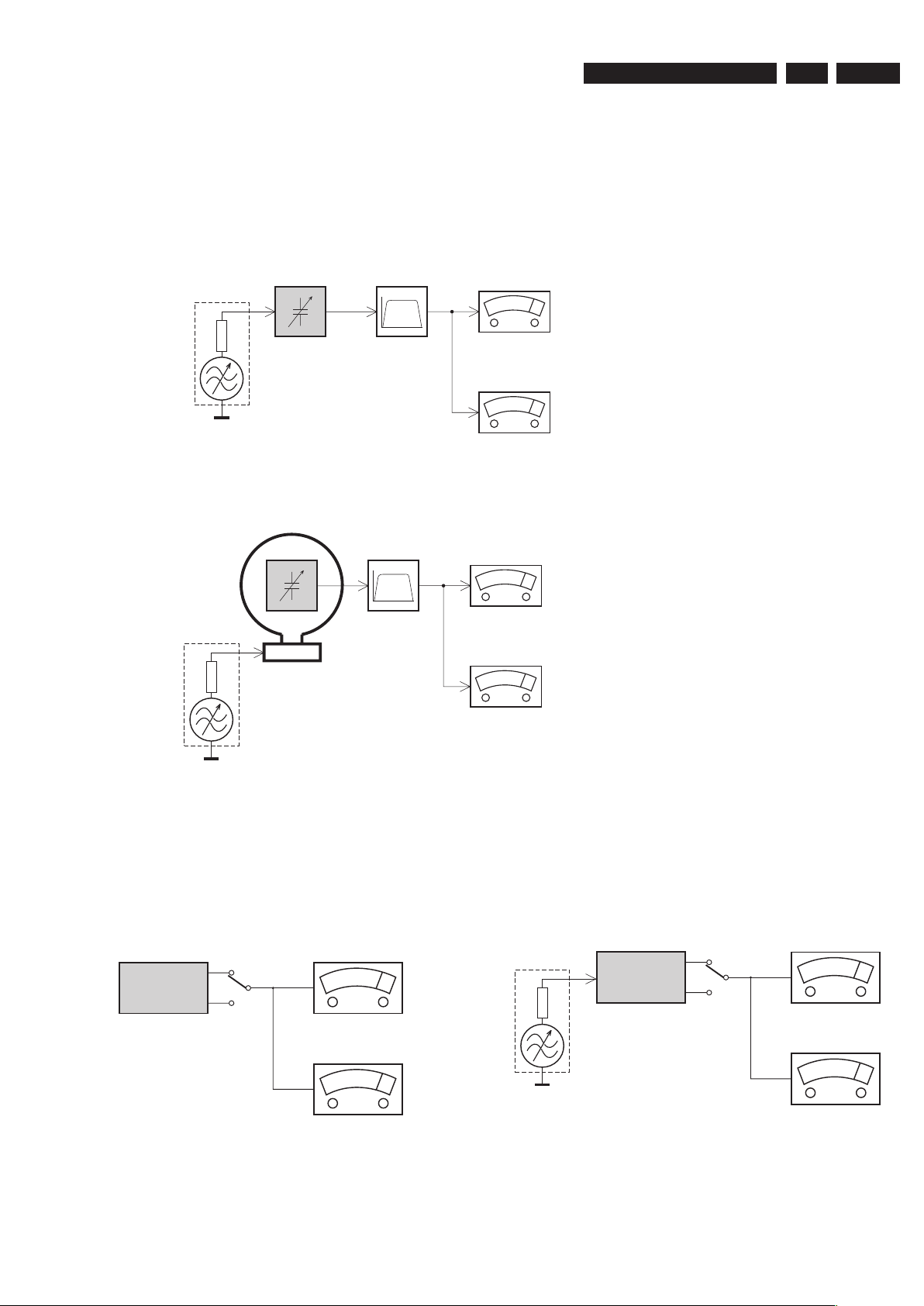
2.
LF Generator
e.g. PM5110
Recorder
Use Universal Test Cassette CrO2 SBC419 4822 397 30069
LEVEL METER
e.g. Sennheiser UPM550
with FF-filter
S/N and distortion meter
e.g. Sound Technology ST1700B
L
R
DUT
or Universal Test Cassette
Fe SBC420 4822 397 30071
LEVEL METER
e.g. Sennheiser UPM550
with FF-filter
S/N and distortion meter
e.g. Sound Technology ST1700B
L
R
DUT
CD
Use Audio Signal Disc
(replaces test disc 3)
SBC429 4822 397 30184
Bandpass
250Hz-15kHz
e.g. 7122 707 48001
LF Voltmeter
e.g. PM2534
DUT
S/N and distortion meter
e.g. Sound Technology ST1700B
Frame aerial
e.g. 7122 707 89001
Tuner AM (MW,LW)
To avoid atmospheric interference all AM-measurements have to be carried out in a Faraday´s cage.
Use a bandpass filter (or at least a high pass filter with 250Hz) to eliminate hum (50Hz, 100Hz).
RF Generator
e.g. PM5326
Ri=50Ω
Bandpass
250Hz-15kHz
e.g. 7122 707 48001
LF Voltmeter
e.g. PM2534
DUT
RF Generator
e.g. PM5326
S/N and distortion meter
e.g. Sound Technology ST1700B
Use a bandpass filter to eliminate hum (50Hz, 100Hz) and disturbance from the pilottone (19kHz, 38kHz).
Ri=50Ω
Tuner FM
MEASUREMENT SETUP
2. Measurements Setup, Service Aid & Lead Free Requirements
EN 6
3139 785 31510
2.
Measurements Setup, Service Aid & Lead Free Requirements
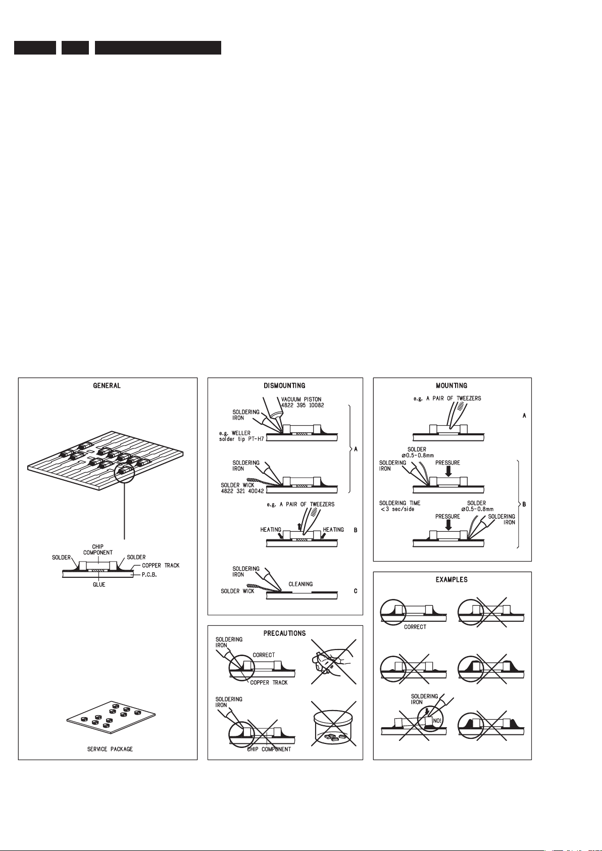
HANDLING CHIP COMPONENTS
SERVICE AIDS
Service Tools:
Universal Torx driver holder .................................. 4822 395 91019
Torx bit T10 150mm ............................................. 4822 395 50456
Torx driver set T6 - T20 ......................................... 4822 395 50145
Torx driver T10 extended ...................................... 4822 395 50423
Compact Disc:
SBC426/426A Test disc 5 + 5A ............................ 4822 397 30096
SBC442 Audio Burn-in Test disc 1kHz ................. 4822 397 30155
SBC429 Audio Signals disc .................................. 4822 397 30184
Dolby Pro-logic Test Disc ...................................... 4822 395 10216
EN 7
3139 785 31510
Measurements Setup, Service Aid & Lead Free Requirements
2.
GB
WARNING
All ICs and many other semi-conductors are
susceptible to electrostatic discharges (ESD)
.
Careless handling during repair can reduce life
drastically.
When repairing, make sure that you are
connected with the same potential as the mass
of the set via a wrist wrap with resistance.
Keep components and tools also at thi
s
potential
.
F
ATTENTION
Tous les IC et beaucoup d’autres
semi-conducteurs sont sensibles au
x
décharges statiques (ESD).
Leur longévité pourrait être considérablement
écourtée par le fait qu’aucune précaution n’es
t
prise à leur manipulation
.
Lors de réparations, s’assurer de bien être relié
au même potentiel que la masse de l’appareil et
enfiler le bracelet serti d’une résistance de
sécurité
.
Veiller à ce que les composants ainsi que les
outils que l’on utilise soient également à ce
potentiel
.
ESD
D
WARNUNG
Alle ICs und viele andere Halbleiter sind
empfindlich gegenüber elektrostatischen
Entladungen (ESD).
Unsorgfältige Behandlung im Reparaturfall ka
n
die Lebensdauer drastisch reduzieren
.
Veranlassen Sie, dass Sie im Reparaturfall über
ein Pulsarmband mit Widerstand verbunde
n
sind mit dem gleichen Potential wie die Mass
e
des Gerätes
.
Bauteile und Hilfsmittel auch auf dieses gleich
e
Potential halten.
NL
WAARSCHUWING
Alle IC’s en vele andere halfgeleiders zi jn
gevoelig voor electrostatische ontladingen (ESD)
.
Onzorgvuldig behandelen tijdens reparatie ka
n
de levensduur drastisch doen verminderen.
Zorg ervoor dat u tijdens reparatie via een
polsband met weerstand verbonden bent me
t
hetzelfde potentiaal als de massa van het
apparaat
.
Houd componenten en hulpmiddelen ook op
ditzelfde potentiaal.
I
AVVERTIMENTO
Tutti IC e parecchi semi-conduttori sono
sensibili alle scariche statiche (ESD)
.
La loro longevità potrebbe essere fortemente
ridatta in caso di non osservazione della pi
ù
grande cauzione alla loro manipolazione.
Durante le riparazioni occorre quindi essere
collegato allo stesso potenziale che quello dell
a
massa dell’apparecchio tramite un braccialetto
a resistenza.
Assicurarsi che i componenti e anche gli utensil
i
con quali si lavora siano anche a questo
potenziale.
GB
ESD PROTECTION EQUIPMENT:
Complete Kit ESD3 (small tablemat, wristband,
connection box, extention cable and earth cable) ...........4822 310 10671
Wristband tester ....................................................................4822 344 13999
CLASS 1
LASER PRODUCT
GB
Warning !
Invisible laser radiation when open.
Avoid direct exposure to beam
.
S
Varning !
Osynlig laserstrålning när apparaten är öppnad och spärren
är urkopplad. Betrakta ej strålen
.
SF
Varoitus !
Avatussa laitteessa ja suojalukituksen ohitettaessa olet alttiina
näkymättömälle laserisäteilylle. Älä katso säteeseen
!
DK
Advarse !
Usynlig laserstråling ved åbning når sikkerhedsafbrydere er
ude af funktion. Undgå udsaettelse for stråling
.
F
"Pour votre sécurité, ces documents doivent être utilisés par
des spécialistes agréés, seuls habilités à réparer votr
e
appareil en panne"
.
GB
Safety regulations require that the set be restored to its original
condition and that parts which are identical with those specified,
be used
Safety components are marked by the symbol
!
.
NL
Veiligheidsbepalingen vereisen, dat het apparaat bij reparatie in
zijn oorspronkelijke toestand wordt teruggebracht en dat onderdelen
,
identiek aan de gespecificeerde, worden toegepast
.
De Veiligheidsonderdelen zijn aangeduid met het symbool
!
F
Les normes de sécurité exigent que l’appareil soit remis à l’état
d’origine et que soient utiliséés les piéces de rechange identiques
à celles spécifiées.
Less composants de sécurité sont marqués
!
D
Bei jeder Reparatur sind die geltenden Sicherheitsvorschriften zu
beachten. Der Original zustand des Geräts darf nicht verändert werden;
für Reparaturen sind Original-Ersatzteile zu verwenden
.
Sicherheitsbauteile sind durch das Symbol
!
markiert.
I
Le norme di sicurezza esigono che l’apparecchio venga rimesso
nelle condizioni originali e che siano utilizzati i pezzi di ricambi
o
identici a quelli specificati
.
Componenty di sicurezza sono marcati con
!
GB
After servicing and before returning set to customer perform a leakage
current measurement test from all exposed metal parts to earth ground to
assure no shock hazard exist. The leakage current must not exceed
0.5mA
.

EN 8
3139 785 31510
2.
Measurements Setup, Service Aid & Lead Free Requirements
2.1 Lead Free Requirements
Pb(Lead) Free Solder
When soldering , be sure to use the pb free solder.
INDENTIFICATION:
Regardless of special logo (not always indicated)
one must treat all sets from 1 Jan 2005 onwards, according next
rules:
Important note: In fact also products of year 2004 must be treated in
this way as long as you avoid mixing solder-alloys (leaded/ lead-free).
So best to always use SAC305 and the higher temperatures belong
to this.
Due to lead-free technology some rules have to be respected by the
workshop during a repair:
• Use only lead-free solder alloy Philips SAC305 with order
code 0622 149 00106. If lead-free solder-paste is required,
please contact the manufacturer of your solder-equipment.
In general use of solder-paste within workshops should be
avoided because paste is not easy to store and to handle.
• Use only adequate solder tools applicable for lead-free solder
alloy. The solder tool must be able
o To reach at least a solder-temperature of 400°C,
o To stabilize the adjusted temperature at the solder-tip
o To exchange solder-tips for different applications.
• Adjust your solder tool so that a temperature around 360°C
– 380°C is reached and stabilized at the solder joint. Heatingtime of the solder-joint should not exceed ~ 4 sec. Avoid
temperatures above 400°C otherwise wear-out of tips will rise
drastically and flux-fluid will be destroyed. To avoid wear-out
of tips switch off un-used equipment, or reduce heat.
• Mix of lead-free solder alloy / parts with leaded solder alloy /
parts is possible but PHILIPS recommends strongly to avoid
mixed solder alloy types (leaded and lead-free).
If one cannot avoid or does not know whether product is leadfree, clean carefully the solder-joint from old solder alloy and
re-solder with new solder alloy (SAC305).
• Use only original spare-parts listed in the Service-Manuals.
Not listed standard-material (commodities) has to be
purchased at external companies.
• Special information for BGA-ICs:
- always use the 12nc-recognizable soldering temperature
profile of the specific BGA (for de-soldering always use the
lead-free temperature profile, in case of doubt)
- lead free BGA-ICs will be delivered in so-called ‘drypackaging’ (sealed pack including a silica gel pack) to protect
the IC against moisture. After opening, dependent of MSLlevel seen on indicator-label in the bag, the BGA-IC possibly
still has to be baked dry. (MSL=Moisture Sensitivity Level).
This will be communicated via AYS-website.
Do not re-use BGAs at all.
• For sets produced before 1.1.2005 (except products of 2004),
containing leaded solder-alloy and components, all needed
spare-parts will be available till the end of the service-period.
For repair of such sets nothing changes.
• On our website www.atyourservice.ce.Philips.com you find
more information to:
BGA-de-/soldering (+ baking instructions)
Heating-profiles of BGAs and other ICs used in
Philips-sets
You will find this and more technical information within the
“magazine”, chapter “workshop news”.
For additional questions please contact your local repair-helpdesk.
EN 9
3139 785 31510
Measurements Setup, Service Aid & Lead Free Requirements
2.
2.2 Service Hints
CAUTION
CHARGED CAPACITORS ON THE SERVO BOARD MAY DAMAGE THE DRIVE
ELECTRONICS WHEN CONNECTING A NEW DRIVE.THAT’S WHY, BESIDES THE SAFETY
MEASURES LIKE
• SWITCH OFF POWER SUPPLY
• ESD PROTECTION
ADDITIONAL ACTIONS MUST BE TAKEN BY THE REPAIR TECHNICIAN.
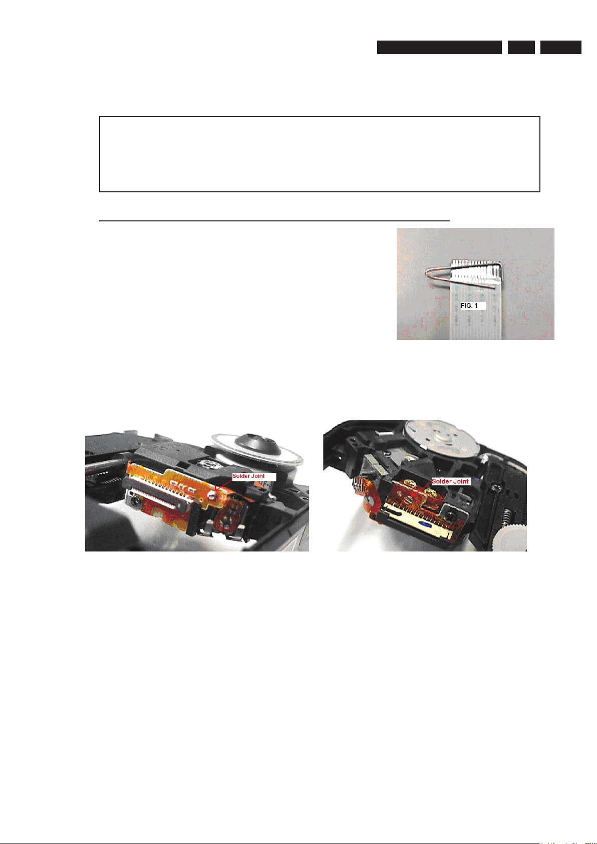
The following steps have to be done when replacing the defective loader :
1. Dismantling of the loader to access the ESD protection point if necessary.
2. Solder the ESD protection point*.
3. Disconnect flexfoil cable from the defective loader.
4. Put a paper clip on the flexfoil to short-circuit the contacts (fig.1)
5. Replace the defective loader with a new loader.
6. Remove paperclip from the flexfoil and connect it to the new loader.
7. Remove solder joint on the ESD protection point.
ATTENTION: The laser diode of this loader is protected against ESD by a solder joint which shortcircuits the laserdiode to ground.
For proper functionality of the loader this solder joint must be remove after connection loader to the set.
Type 1 Type 2
(ESD protection point is accessible from top of loader) (ESD protection point is accessible from bottom of the loader)
*Only applicable for defective loader needed to be sent back to supplier for failure analysis and to support backcharging
evidence.
This is also applicable for all partnership workshops.
EN 10
3139 785 31510
Quick Start Guide
Connect
Set up
Enjoy
1
2
3
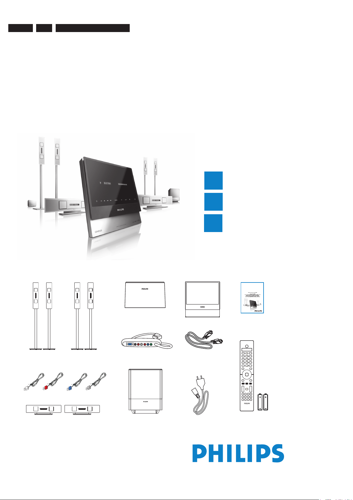
What’s in the box?
Front speakers
(left & right)
Rear speakers
(left & right)
Centre speakers
(front & rear)
DVD system
AV subwoofer Remote Control
and 2 batteries
h
s
i
lg
nE
DVD/ SACD HOME THEATER SYSTEM
HTS9800W
User Manual
User manual
Junction Box
AV Wireless
Receiver Box
DVD/ SACD Home Theater System HTS9800W
VGA cable
(use this cable to connect the
Junction Box to AV subwoofer)
Speaker cables
Power cable
x 2
3.
Directions for use
3. Directions For Use

EN 11
3139 785 31510
1
Connect
FRONT
LEFT
REAR
LEFT
TO SUB-
WOOFER
VIDEO
AUDIO
OUT IN
TV (rear)
Junction box
General Setup Page
Disc Lock
OSD Language
Screen Saver
DivX(R) VOD Code
English
Espanõl
Français
Português
RIGHTCENTER LEFT
SPEAKERS
Junction box
DVD system
FRONT
RIGHT
FRONT
LEFT
FRONT CENTER
To AC
power
AV
subwoofer
Extend the FM
pigtail antenna and
place it where the
reception
is best
received.
REAR CENTER
REAR
LEFT
REAR
RIGHT
To AC
power
RIGHT CENTER LEFT
SPEAKERS
E Connect the Junction Box to the
TV
Connect the scart cable from the Junction box to
the SCART IN socket on your TV.
To AC
power
Base view of AV
Wireless
receiver box
B Connect the front speakers and
subwoofer
C Connect the rear speakers and
AV wireless receiver box
VGA cable
D Position the speakers and
subwoofer
Proper speakers and system placement is
important to ensure optimum sound performance.
A
Place the FRONT CENTER speaker above
or close to the TV.
B
Place the SUBWOOFER on the oor, at least
one metre away from the TV.
C
Place the FRONT LEFT/RIGHT speakers at
equal distances from the TV.
D
Place the REAR CENTER speaker at normal
listening ear level.
E
Ensure the front of the AV Wireless Receiver
box (with Philips logo) is facing towards the
DVD system.
Note If there is an interference on your
HTS9800W speakers or existing wireless
network in your home, see the User Manual
– “Troubleshooting”.
Note For optimal wireless performance, ensure
that the AV wireless receiver box is not placed in
an enclosed area.
B
Base view of the speaker stand
Both the
coloured
stickers must
match
A
C
Placement and Connections
A Assemble the speakers
A
Connect the speaker stand with the supplied
speaker wire. Match the colour of the speaker
wire to the colour of the socket on the base of
the speaker stand.
Hold down the socket tab while inserting the
stripped portion of the speaker wire into the tab.
Then, release the socket tab to lock the wire into
position.
B
Match the coloured stickers on the rear of the
speaker and the inside of the speaker stand.
Position the speakers as shown and ensure the
connectors t. See the above illustration.
C
Secure the speaker stand with the supplied
screws.
Directions For Use
3.
EN 12
3139 785 31510
3.
Directions for use
2
Set up
FRONT
LEFT
REAR
LEFT
FRONT CENTER
REAR C ENTER
FRONT
RIGHT
REAR
RIGHT
AV
WIREL ESS
RECEI VER
BOX
TV
DVD SYS TEM
SUB
WOOFE R
DIGITAL IN L AUX IN R COMPONENT VIDEO
Pr Pb Y
TO SUBWOOFER
VIDEO
SCART IN
AUDIO
OUT IN
TV
TV (rear)
Junction box
General Setup Page
Disc Lock
OSD Language
Screen Saver
DivX(R) VOD Code
English
Espanõl
Français
Português
E Connect the Junction Box to the
TV
Connect the scart cable from the Junction box to
the SCART IN socket on your TV.
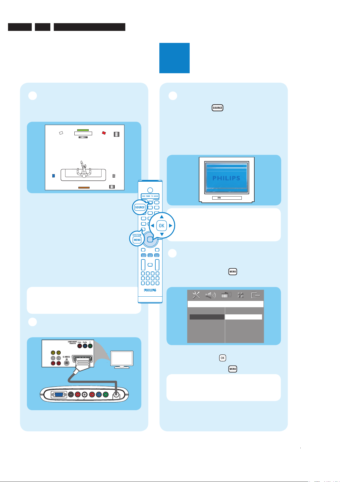
A Finding the viewing channel
A Press SOURCE
on the remote control
until “DISC” appears on the display panel.
B Turn on the TV. Use the TV’s remote control
to select the correct viewing channel for the
DVD system.
You should see the blue DVD background on
the TV.
Note
To search for the correct viewing
channel, press the CHANNEL DOWN button
on the TV’s remote control repeatedly (or AV,
SELECT button) until you see the blue DVD
background.
B Select the display language on
the screen
A
Press SYSTEM MENU
on the remote.
B Press É to select { General Setup Page }.
C Use
keys to select a language option in the
menu and press OK
to con rm.
D Press SYSTEM MENU
to exit.
Note The language selected here is only for
the system menus that are shown on the TV
while operating this DVD system, not for the
DVD disc menu.
There are various system setup options (Audio
Setup, Video Setup, Preference Setup) available on
this DVD system. Refer to the accompanying user
manual for more information.
D Position the speakers and
subwoofer
Proper speakers and system placement is
important to ensure optimum sound performance.
A
Place the FRONT CENTER speaker above
or close to the TV.
B
Place the SUBWOOFER on the oor, at least
one metre away from the TV.
C
Place the FRONT LEFT/RIGHT speakers at
equal distances from the TV.
D
Place the REAR CENTER speaker at normal
listening ear level.
E
Ensure the front of the AV Wireless Receiver
box (with Philips logo) is facing towards the
DVD system.
Note If there is an interference on your
HTS9800W speakers or existing wireless
network in your home, see the User Manual
– “Troubleshooting”.
EN 13
3139 785 31510
Directions For Use
3.
Quick Start Guide
What’s in the box?
2006 © Koninklijke Philips N.V.
All rights reserved.
12 NC 3139 246 19051
www.philips.com
Need help?
User Manual
See the user manual that came with your Philips DVD/SACD Home Theater System.
Online
Go to www.philips.com/support.
3
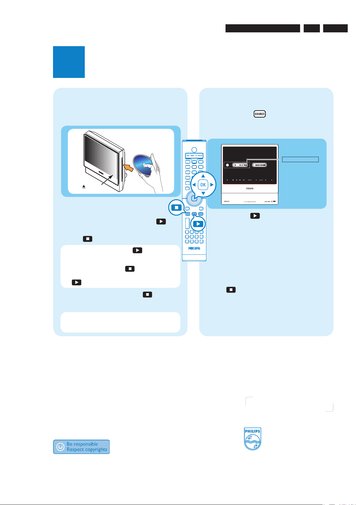
Enjoy
Start disc playback Listen to radio
Front speakers
(left & right)
Centre speakers
A Press SOURCE
on the remote control
repeatedly to select the TUNER mode.
The display panel will show “AUTO INSTALL
PRESS PLAY”.
B
Press and hold
(PLAY) on the remote
control until “INSTALL TUNER” appears on
the display panel.
All the available radio stations with strong
signal strength will be stored automatically.
Once complete, the last tuned radio
station will be played back.
C
Once complete, use keys to select a
preset radio station.
D
To delete a preset radio station, press and
hold
(STOP)
until “PRESET DELETED”
appears.
AUTO INSTALL ....
DVD/ SACD Home Theater System HTS9800W
A
Insert a disc into the disc slot.
Make sure the disc label is facing out.
(EJECT)
B
Playback will start automatically.
C If the disc menu appears, use
keys to
select an option in the menu and press
(PLAY) on the remote to start playback.
D Press (STOP) to stop playback.
Note When you press the
(PLAY)
button again, the playback will resume from
where it last stopped. To start playback from
the beginning, press the
(STOP)
button
twice to cancel the resume mode. Press
(PLAY) to start playback.
E To eject the disc, press and hold (STOP)
or press ç (EJECT) on the DVD system
panel.
Note You may also access the same
functions by using the corresponding touch
screen buttons on the DVD system panel.
DVD system’s
display panel
Speaker cables
EN 14
3139 785 31510
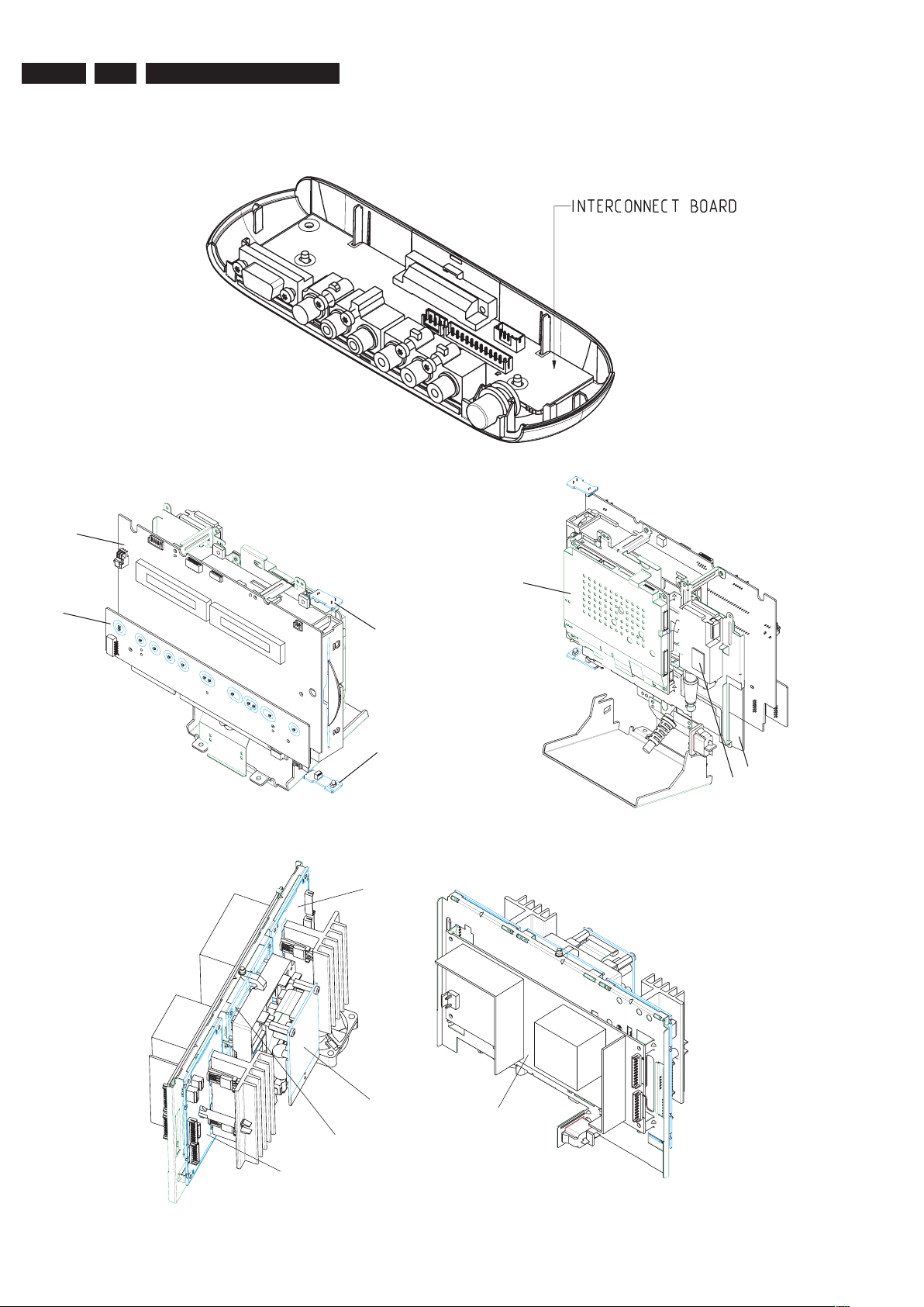
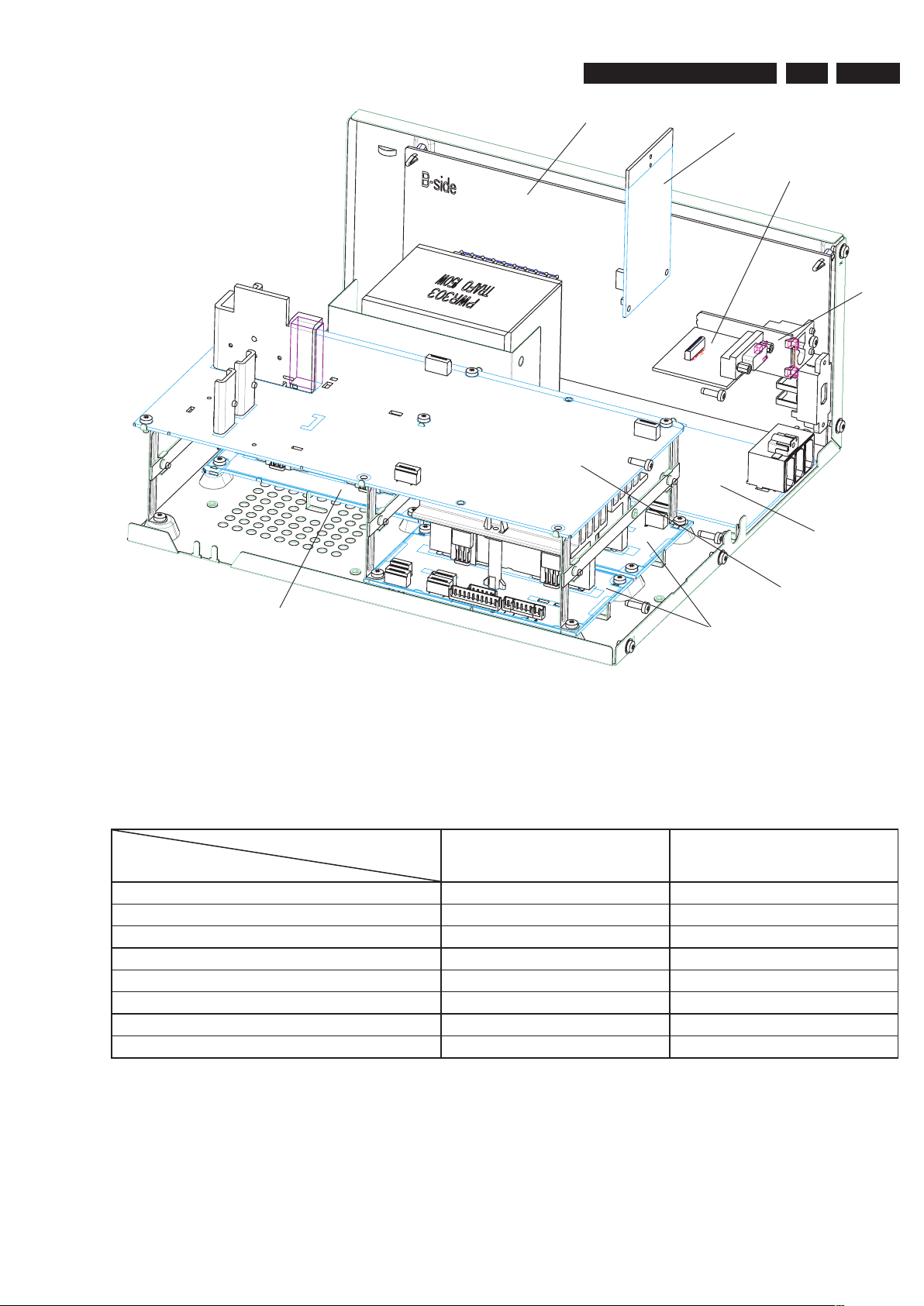
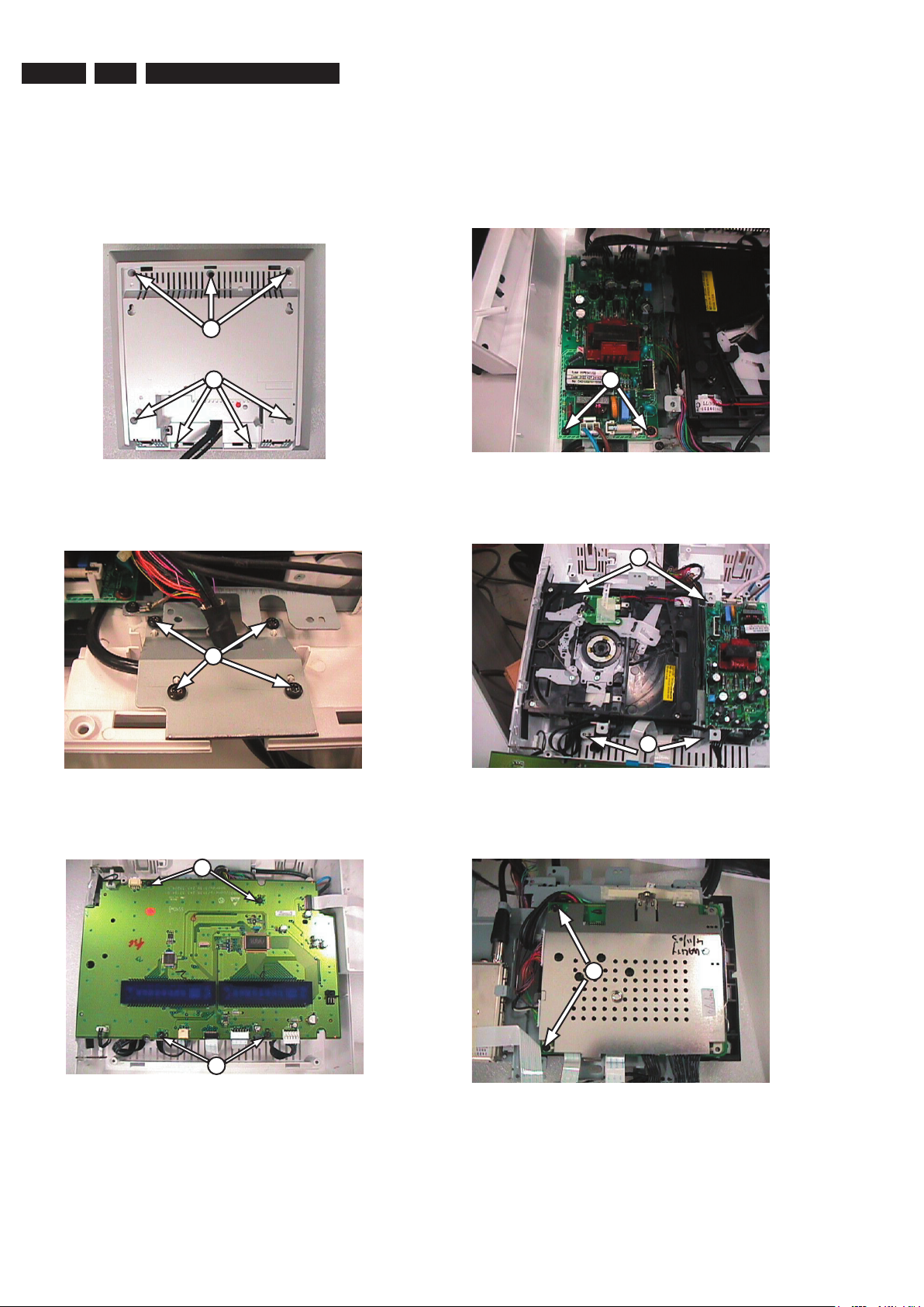
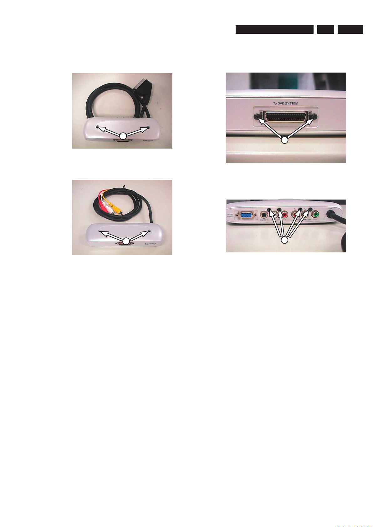
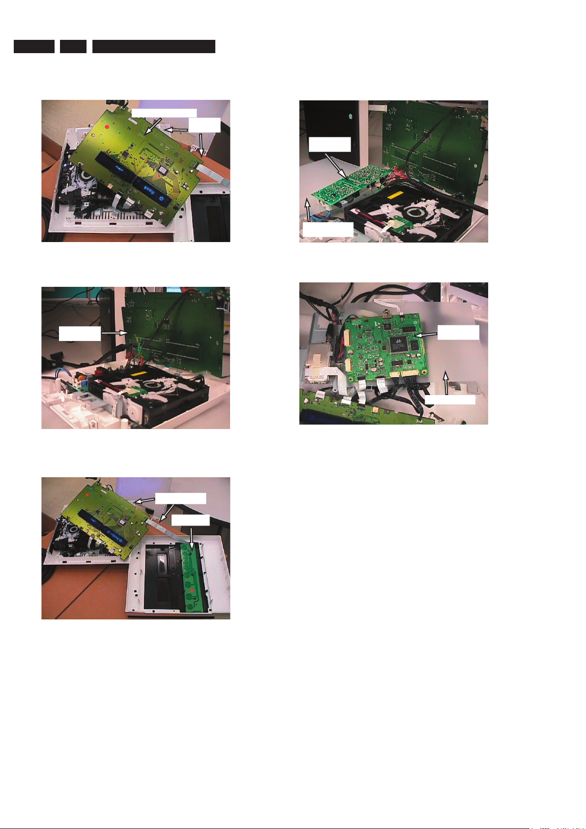
4) Loosen 2 screws to remove PSU Module.
Figure 4-4
5) Loosen 4 screws to remove Bracket Pos 125.
Figure 4-5
6) Loosen 4 screws to remove Shield.
Figure 4-6
4.1 Dismantling of the Main Unit
1) Remove Cover and loosen 7 screws as shown in
Figure 4-1.
Figure 4-1
2) Loose 4 screws to remove the Bracket Pos 131.
Figure 4-2
3) Loosen 4 screws to remove Display Board.
Figure 4-3
4. Dismantling Instructions
4
3
3
6
4.
Dismantling Instructions & Service Positions
1
1
2
5
5
EN 15
3139 785 31510
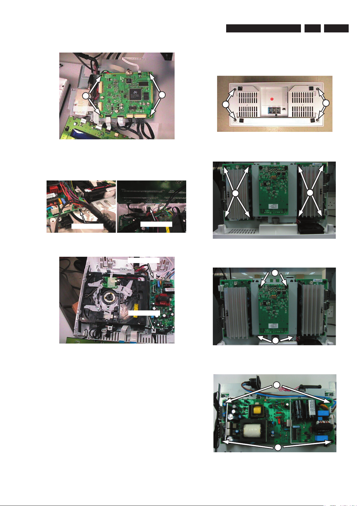
7) Loosen 2 screws to remove the MPEG Board.
Figure 4-7
Note: Please change from Ground Point A to Ground Point B
to achieve Service Position for Display Board.
Figure 4-8 Figure 4-9
Figure 4-10
7
7
Dismantling Instructions & Service Positions
4.
GND POINT A
GND POINT B
4.2 Dismantling of the Wireless Box Surround
1) Loosen 4 screws to remove the Cover for the Wireless
Box Surround.
Figure 4-11
2) Loose 4 screws each to remove the Amplifier Board.
Figure 4-12
3) Loose 4 screws to remove the Wireless Receiver
Figure 4-13
4) Loosen 4 screws to remove the PSU Module.
Figure 4-14
1
1
2
2
GND POINT B
GND POINT A
3
3
4
4

EN 16
3139 785 31510
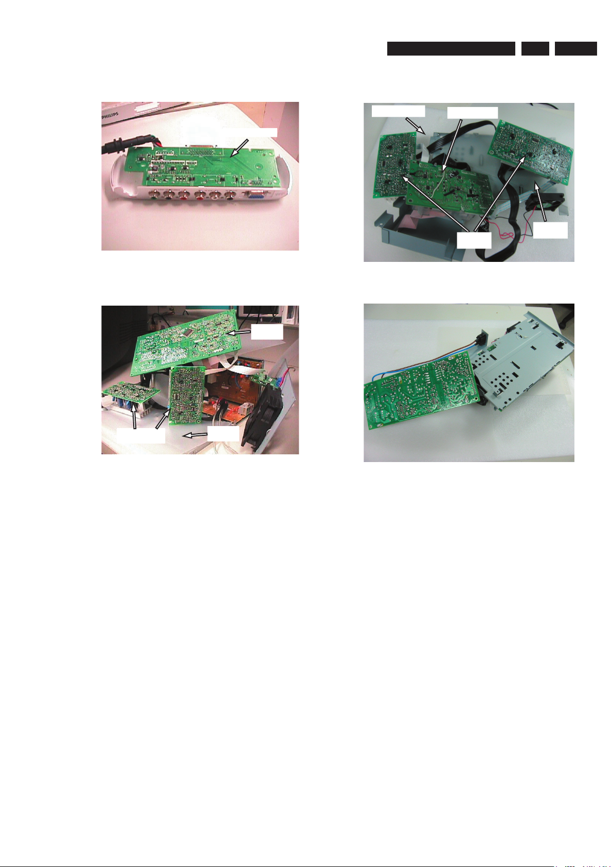
4.3 Dismantling of Subwoofer Power Box
1) Remove the Base as shown in Figure 4-15.
Subwoofer Figure 4-15
2) Loosen 5 screws as shown in Figure 2.
Subwoofer Figure 4-16
3) Loosen 16 screws as shown in Figure 3 and pull the
Power-Box Assy.
Subwoofer Figure 4-17
4.
Dismantling Instructions & Service Positions
A
B
B
C
C
4) Loosen 2 screws as shown in Figure 4 & Figure 5 to
remove the shield.
Subwoofer Figure 4-18 Subwoofer Figure 4-19
5) Loosen 4 screws as shown in Figure 6 to remove the
Interface Board.
Subwoofer Figure 4-20
6) Loosen 8 screws as shown in Figure 7 to remove the
Amplifier Board.
Subwoofer Figure 4-21
D
F
F
E
E
D
EN 17
3139 785 31510
Dismantling Instructions & Service Positions
4.
4.4 Dismantling of the Junction Box
1) Loosen 2 screws.
Junction Box Europe Figure 4-22
Junction Box AP Figure 4-23
2) Loosen 2 screws.
Junction Box Figure 4-24
3) Loosen 4 screws.
Junction Box Figure 4-25
G
G
H
I
EN 18
3139 785 31510
4.
Dismantling Instructions & Service Positions
4.5 Service Positions - Main Unit
Service Position - Display Board (Topview)
Service Position- Display Board (Bottomview)
Service Position - Front Panel Board
Service Position - PSU Unit
Service Position - MPEG Board
Display Board (Top)
Insulation
Sheet
Display Board
(Bottom)
Front Panel
Insulation Sheet
PSU module
Insulation Sheet
MPEG Board
Insulation Sheet
EN 19
3139 785 31510
Dismantling Instructions & Service Positions
4.
Service Position - Junction Box
Service Position - Subwoofer
Service Position - Amplifier & Interface Board
Service Position - PSU Module
4.6 Service Positions - Junction Box, Subwoofer unit & Wireless Box Surround
Junction Box
Insulation
Sheet
Insulation Sheet
Interface Board
Amplifier
Board
Interface
Board
Amplifier Board
Insulation
Sheet
EN 20
3139 785 31510
5.
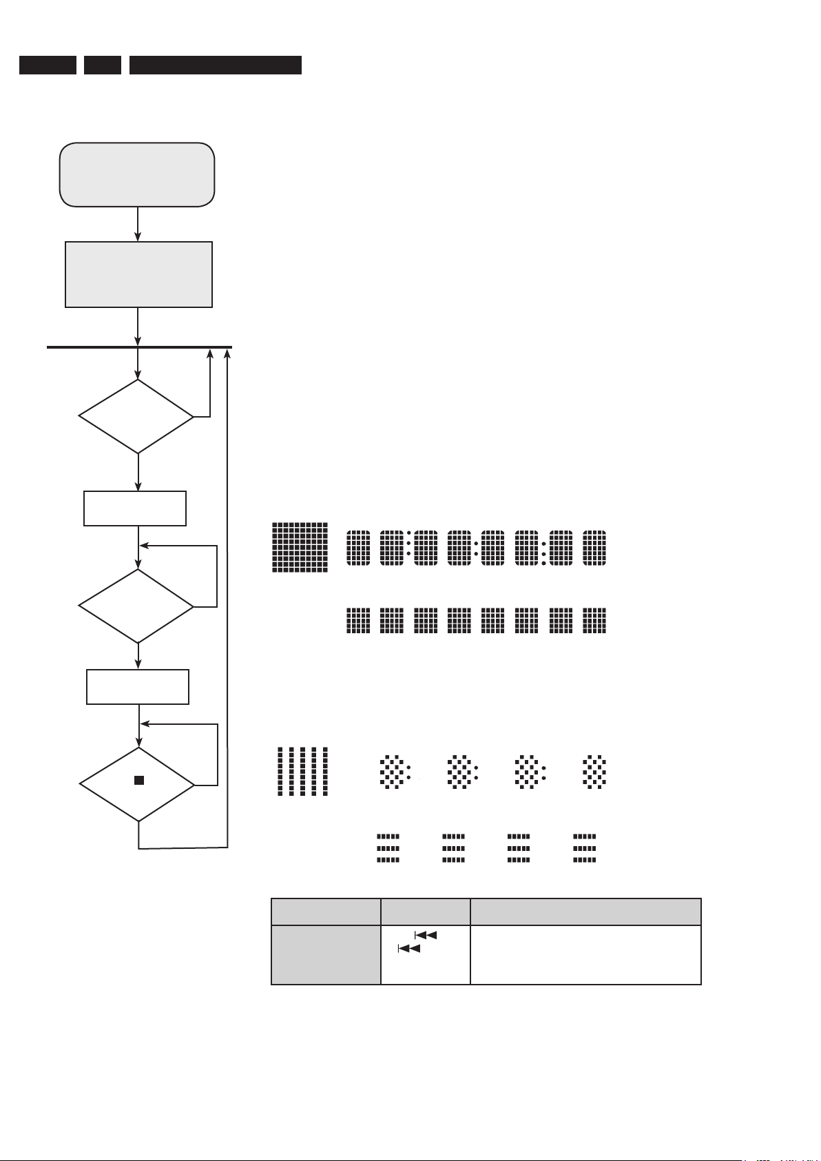
5. Service Test Program-Display Test
To start service test program
select AUX source. Press
2-5-8. All 3 numbers must be
keyed in within 5 seconds.
Display shows
“SERVICE”
followed by ROM version
“S-Vxx-yy”
5.1 Display Test
Purpose:
This test is used to check the driving circuits, the display and whether there are any shortcircuits, open-circuits or any other defects.
Following display patterns are used to test the display and its connections to µP.
Pattern 1:
All display control pins are ON
Mode Dim 1 is selected.Brightness is 75%.
- to check for open-circuits
Pattern 2:
Alternate display control pins are ON (Test Pattern: 0x55)
Mode Dim 2 is selected. Brightness is 25%.
- to check for short-circuits
TEST Activated with ACTION
EEPROM FORMAT
TEST
to Exit
Load default data. Display shows “NEW”.
Caution!
All presets from the customer will be lost!!
S refers to Service Mode
V refers to Version
xx refers to Software version number of BEA
(counting up from 01 to 99)
yy refers to Software version number of Front uP
(counting up from 01 to 99)
Main Menu
Key
“Display Test”
triggered ?
Display Test
N
Activate and
display “Pattern1”
Key
“Display Test”
triggered ?
Y
Y
Select AUX source, press 2,5,8. (All 3 numbers must be keyed within 5 seconds).
N
Activate and
display “Pattern2”
Key
“ ”
triggered?
Y
N
Service Test Program

EN 21
3139 785 31510
5.
5.1.1 Reprogramming of DVD version Matrix
After repair, the customer setting and region code may be lost.
Reprogramming will put the set back in the state in which it has left
the factory, ie. with the default setting and the allowed region code.
Model Region Region Code TV Type
HTS 9800W/12 Europe 2 PAL
HTS 9800W/37 NAFTA 1 NTSC
HTS 9800W/55 Latam 4 PAL
To reprogram do as follows:
1) Power up the set and select
DISC source.
2) Open tray by press “OPEN/CLOSE” button on the set or press
and hold “STOP” button on the RC.
3) Press the following buttons on the Remote Control:
Open Tray <9> <9> <9> <9> <AUDIO> <1> ....for HTS 9800W/
12
Open Tray <9> <9> <9> <9> <AUDIO> <2> ....for HTS 9800W/37
Open Tray <9> <9> <9> <9> <AUDIO> <3> ....for HTS 9800W/55
4) The display shows ‘YYYY-ZZ’ and the tray will close.
YYYY = model number (eg. 8300, 8500, etc.)
ZZ = slash stroke version (eg. 01, 69, etc.)
5.1.2 Procedure for check Software version
1) Power up the set and select DISC source.
2) Open tray by press “OPEN/CLOSE” button on the set or press
and hold “STOP” button on the RC.
3) Press “DISPLAY” button on the Remote control.
4) The TV screen will shows:
SERVO: nnnnnnnn
G58M1 Vxx YYYY-ZZ -AA-BB
xx = version number
YYYY = model number (eg. 8000, 8340, etc.)
ZZ = slash stroke version (eg. 01, 69, etc.)
AA = region code
BB = Front uP software version number
nnnnnnnn = servo version number
5.1.3 Burning of firmware
1. Unzip the zip-archive attached with this service information.
2. Start the CD burning software and create a new CD Project
(Data disc) with the following settings:
a. File System: ISO9660
b. Format: MODE 2/XA
c. Recording format: Single Session (Track at once),
Finalized CD
3. Place the content of the zip-archive into the root directory of the
new CD project.
4. Burn the data onto a blank CDR or CDRW.
Note: ISO9660 is mandatory, UDF discs are not supported!
The final CDROM must not contain any other data except
the file from the zip-archive.
5.1.4 Procedure to upgrade the firmware
1. Power up the set and open tray.
2. Insert the prepared Upgrade CDROM and close the tray.
3. The set will display:
1) “LOAD” (after read the disc, the tray is ejected
out)
2) “ERASE” (Erasing Disc)
3) “WRITE” (Writing Disc)
4) “ERROR” (if unsuccessful)
5) “UPG END” (only a short moment, if successful)
6) “DISC” follow by “LOAD” and the tray is pulled in.
The TV screen will show the following messages during upgrading.
Between Message 1 and 2, Tray will be open for user to remove the
upgrade disc.
1. “Upgrade File Detected
File Copying”
2. “Upgrade File Detected
Upgrading”
The upgrading time should not take more than 5 minutes.
Reminder: DO NOT unplug the set until upgrade is finished. The
tray will close after the upgrade is complete.
5.1.5 Procedure to check the firmware version to
confirm upgrading
1. Power up the set and open tray.
2. Press the <Display> button on the Remote Control.
3. The firmware version will be displayed on the top left hand corner
of the OSD.
Caution: Do not unplug the set until upgrade is completed.
5.1.6 Trade Mode
Trade mode is a feature that will block all set keys when enabled. It is
for dealers to prevent customers fromremoving disc, changing source
etc using the set keys.Rotary and Remote Control (RC) keys are still
allowed inTrade mode.
To activate Trade Mode:
1) Power up the set and select
DISC source.
2) Open tray by press “OPEN/CLOSE” button on the set
or press and hold “STOP” button on the RC.
3) Then press buttons <2> <5> <9> on the RC.
4) The display shows
‘TRA ON’ and the tray will close.
Trade Mode is now enabled.
To deactivate Trade Mode:
1) Power up the set and select
DISC source.
2) Open tray by press and hold “STOP”button on the RC.
3) Then press buttons <2> <5> <9> on the RC.
4) The display shows
‘TRA OFF’ and the tray will close.
Trade Mode is now disabled.
Service Test Program

EN 22
3139 785 315105.
Service Test Program
Notes:
EN 23
3139 785 31510
6.
10K
VS
RDS IC
M62429FP
/RST
POWER AMP
OUT
U C D
L/
R
10K
U C D
L/
R
POWER AMP
TUNER
74HC4052
(TM 10)
1n0
POWER AMP
L/
R
SAA6581T
M62429FP
GND
11 12 13 14
8765 201918171615
F
G
H
I
F
E
D
C
3 4 5 6 7 8 9 1
0
15 16 17 18 19 20
1413
K
4321
J
L
M
N
O
P
P
O
A
B
C
D
E
N
M
L
K
J
I
H
G
B
A
1 2
1211109
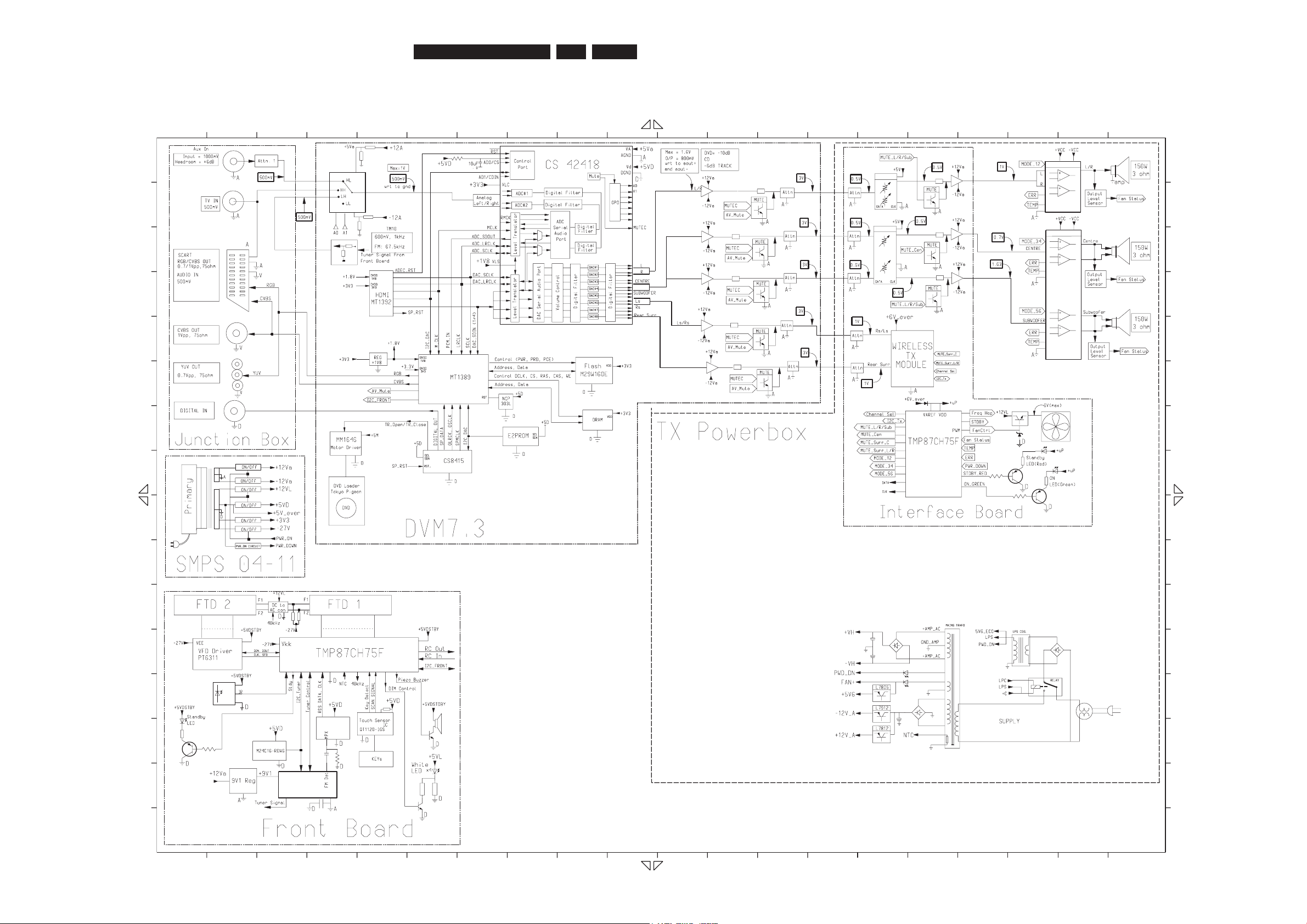
3139_249_3297_Block_Diagram_Pg1.pdf_030806
6. Block Diagram
Block Diagram, Wiring Diagram
 Loading...