

Page 1
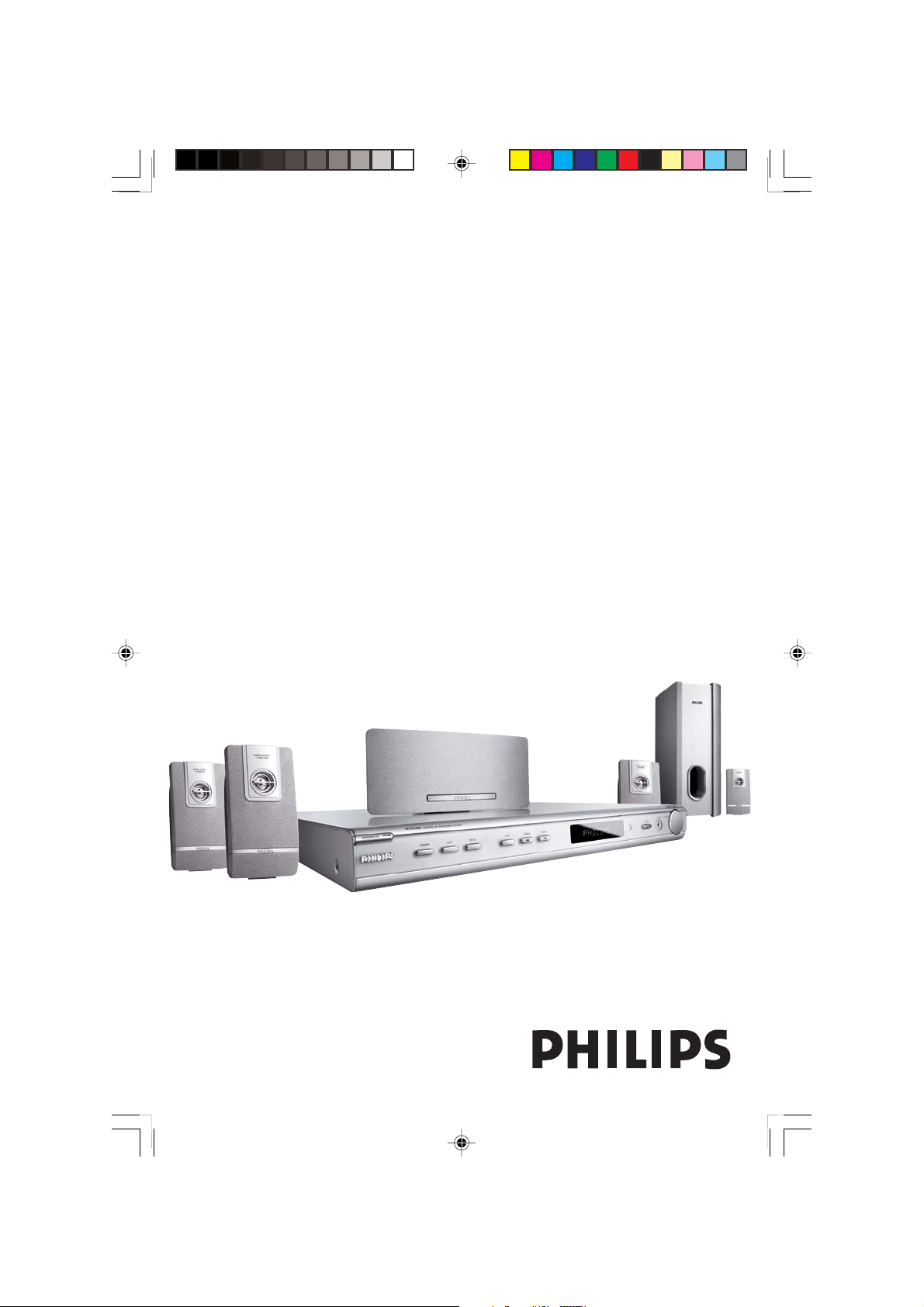
DIGITAL A/V SURROUND RECEIVER
User manual
Thank you for choosing Philips.
Need help fast?
Read your Quick-Use Guide and/or User Manual first for quick
tips that make using your Philips product more enjoyable.
If you have read your instructions and still need assistance,
you may access our online help at www.philips.com/support
HTR5000
Page 2
Important notes for users in the
U.K.
Mains plug
This apparatus is fitted with an approved 13
Amp plug. To change a fuse in this type of plug
proceed as follows:
1 Remove fuse cover and fuse.
2 Fix new fuse which should be a BS1362 5
Amp, A.S.T.A. or BSI approved type.
3 Refit the fuse cover.
If the fitted plug is not suitable for your socket
outlets, it should be cut off and an appropriate
plug fitted in its place.
If the mains plug contains a fuse, this should
have a value of 5 Amp. If a plug without a fuse
is used, the fuse at the distribution board
should not be greater than 5 Amp.
Note: The severed plug must be disposed of to
avoid a possible shock hazard should it be
inserted into a 13 Amp socket elsewhere.
How to connect a plug
The wires in the mains lead are coloured with
the following code: blue = neutral (N),
brown = live (L).
¶ As these colours may not correspond with the
colour markings identifying the terminals in
your plug, proceed as follows:
– Connect the blue wire to the terminal
marked N or coloured black.
– Connect the brown wire to the terminal
marked L or coloured red.
– Do not connect either wire to the earth
terminal in the plug, marked E (or e) or
coloured green (or green and yellow).
Before replacing the plug cover, make certain
that the cord grip is clamped over the sheath
of the lead - not simply over the two wires.
Copyright in the U.K.
Recording and playback of material may
require consent. See Copyright Act 1956 and
The Performer’s Protection Acts 1958 to 1972.
Italia
DICHIARAZIONE DI CONFORMITa’
Si dichiara che l’apparecchio HTR5000 PHILIPS
risponde alle prescrizioni dell’ar t. 2 comma 1 del
D.M. 28 Agosto 1995 n. 548.
Fatto a Eindhoven
Philips Consumer Electronics
Philips, Glaslaan 2
5616 JB Eindhoven, The Netherlands
Norge
Typeskilt finnes på apparatens underside.
Observer: Nettbryteren er sekundert
innkoplet. Den innebygde netdelen er
derfor ikke frakoplet nettet så lenge
apparatet er tilsluttet nettkontakten.
For å redusere faren for brann eller elektrisk
støt, skal apparatet ikke utsettes for regn eller
fuktighet.
CAUTION
Use of controls or adjustments or
performance of procedures other
than herein may result in hazardous
radiation exposure or other unsafe
operation.
VAROITUS
Muiden kuin tässä esitettyjen
toimintojen säädön tai asetusten
muutto saattaa altistaa vaaralliselle
säteilylle tai muille vaarallisille
toiminnoille.
This AV Receiver is in
conformity with the EMC
directive and low-voltage
directive.
2
8239 300 38591
Page 3
Index
English ------------------------------------------------ 4
Français -------------------------------------------- 23
English
Français
Manufactured under license from Dolby
Laboratories. “Dolby”, “Pro Logic” and
the double-D symbol are trademarks of
Dolby Laboratories.
Manufactured under license from Digital
Theater Systems, Inc. U.S. Pat. No’s.
5,451,942; 5,956,674; 5,974,380; 5,978,
762; 6,226,616; 6,487,535 and other U.S.
and world-wide patents issued and
pending. “DTS” and “DTS Digital
Surround” are registered trademarks of
Digital Theater Systems, Inc. Copyright
1996, 2003 Digital Theater Systems, Inc.
All Rights Reversed.
This product complies with the radio
interference requirements of the
European Community.
Español --------------------------------------------- 42
Español
Deutsch --------------------------------------------- 61
Deutsch
Nederlands ---------------------------------------- 80
Nederlands
Italiano ---------------------------------------------- 99
Italiano
8239 300 38591
3
Page 4

Contents
English
General Information
Supplied accessories ............................................ 5
Care and safety information .............................. 5
Connections
Step 1: Set up the speakers................................ 6
Step 2: Placing the speakers and subwoofer .. 6
Step 3: Connecting speakers and subwoofer 7
Step 4: Connecting FM/MW antennas ............ 8
Step 5: Connecting the power cord ................ 8
Optional Connections - Playback
Connecting to TV/VCR/other audio
devices .................................................................... 9
Connecting to a DVD/SACD player .............. 10
Option 1: Using 6 Channel In jacks.......... 10
Option 2: Using Coaxial In jack ................ 10
Option 3: Using Optical In jack................. 10
Optional Connections - Recording
Connecting to a recording device.................. 11
Functional Overview
Main unit and remote control......................... 12
Control buttons available on the
remote only ................................................... 13
Getting Started
Step 1: Inser ting batteries into the
remote control ................................................... 14
Using the remote control to operate
the system ...................................................... 14
Step 2: Switching On/Off.................................. 14
Switching to an active mode ...................... 14
Switching to standby mode ........................ 14
Step 3: Setting the speakers...................... 14–15
Adjusting the speaker output levels......... 15
Sound Controls
Selecting surround sound................................. 16
Selecting digital sound effects.......................... 16
Adjusting the Bass/Treble level........................ 16
Volume Controls and Other
Features
Volume Control .................................................. 17
Night Mode - turning on/off ............................ 17
Dimming system’s display screen.................... 17
Setting the Sleep Timer ..................................... 17
Tuner Operations
Tuning to radio stations .................................... 18
Presetting radio stations................................... 18
Automatic presetting................................... 18
Manual presetting ......................................... 18
Selecting a preset radio station....................... 19
Tr oubleshooting .........................................20
Specifications ............................................... 21
Glossary ........................................................ 22
4
8239 300 38591
Page 5
General Information
)
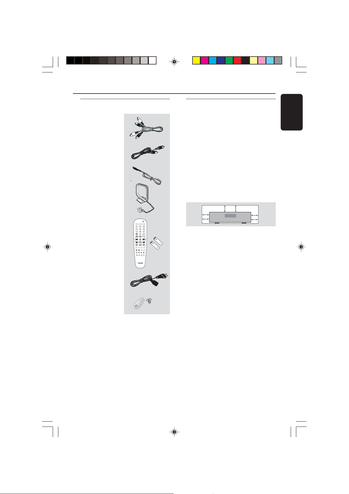
Supplied accessories
Audio cables
(red, white)
Coaxial cable
FM wire antenna
MW loop antenna
TV
DISC
Remote control and
two batteries
DVD MENU
SYSTEM
STOP RESUME
SURROUNDSOUND NIGHT MUTE
REPEAT REPEAT SLEEP DIM
SUBW REAR CENTER TV VOL
DISC TUNER AUX
PLAY/PAUSE
Care and safety information
Avoid high temperatures, moisture,
water and dust
–Apparatus shall not be exposed to
dripping or splashing.
– Do not place any sources of danger on
the apparatus (e.g. liquid filled objects,
lighted candles).
Do not block any ventilation
openings
– Place the apparatus in a location with
adequate ventilation to prevent internal
heat build up. Allow at least 10cm
(4 inches) of free space all around the
apparatus for adequate ventilation.
10 cm
(4 inches)
10 cm
(4 inches)
VOL
Finding a suitable location
PHILIPS
DVD Home Cinema System
(4 inches
10 cm
– Place the player on a flat, hard, stable
surface.
– Do not position the set on top of
other equipment that might heat it up (e.
g. DVD player or amplifier).
English
Power cable
Speaker brackets
and screws
Care of the cabinet
– Use a soft cloth slightly moistened
with a mild detergent solution. Do not
use a solution containing alcohol, spirits,
ammonia or abrasives.
(5x)
5
8239 300 38591
Page 6
Connections
English
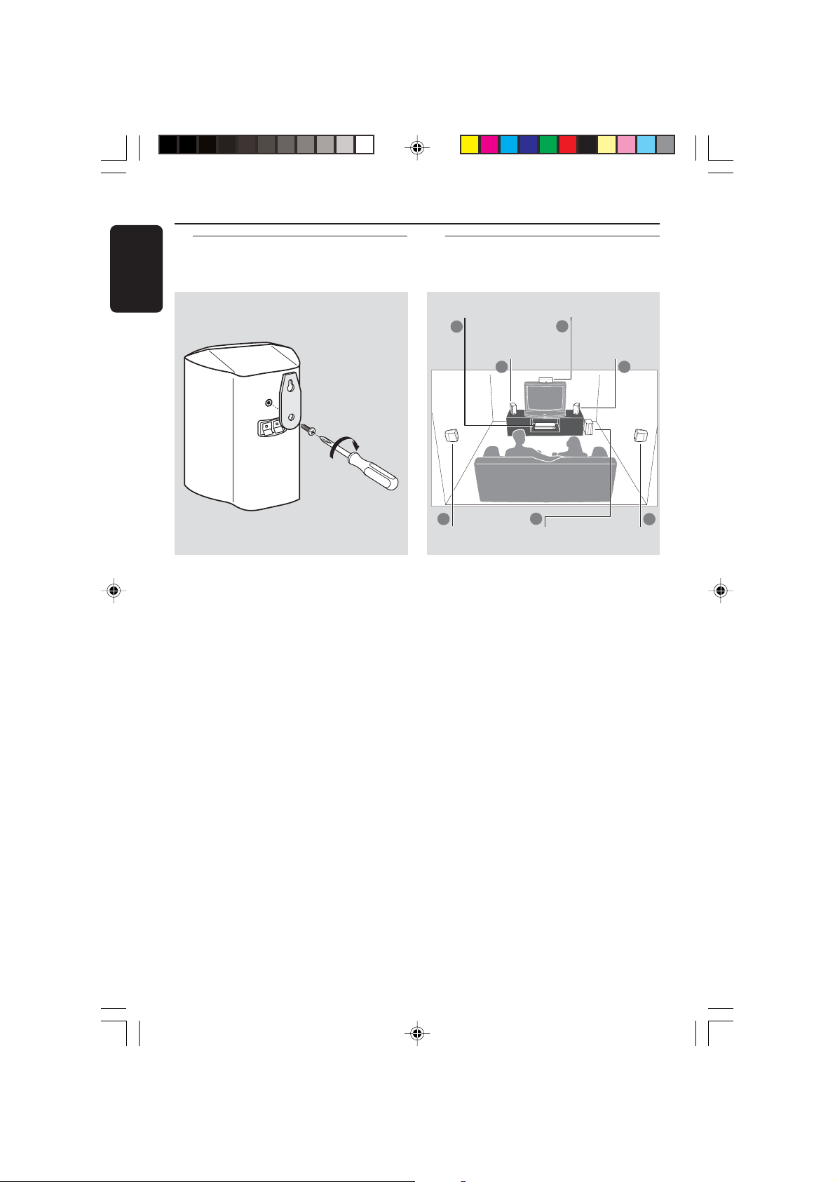
Step 1: Set up the speakers
You can choose to hang the speakers on
the wall. Attach the supplied bracket
firmly to the rear of speakers using the
supplied screws. Then mount a screw
(not supplied) on the wall where the
speaker is to be hung and hook the
speaker securely onto the mounted
screw.
CAUTION!
You should get a qualified person to
attach the brackets to the wall. DO
NOT do it by yourself to avoid
unexpected damage to the
equipment or injury to personnel.
Helpful Hints:
– The rear speakers are labelled as REAR L
(left) or REAR R (right).
– The front speakers are labelled as
FRONT L (left) or FRONT R (right).
Step 2: Placing the speakers
and subwoofer
4
Subwoofer
Centre
speaker
2
Front Speaker
(Right)
1
Rear speaker
(Right)
AV Receiver
2
Front Speaker
(Left)
1
3
Rear speaker
(Left)
For best possible surround sound, all the
speakers (except subwoofer) should be
placed at the same distance from the
listening position.
1 Place the front left and right speakers at
equal distances from the TV and at an
angle of approximately 45 degrees from
the listening position.
2 Place the centre speaker above the TV or
the AV receiver so that the centre
channel’s sound is localised.
3 Place the rear speakers at normal
listening ear level facing each other or
mounted on the wall.
4 Place the subwoofer on the floor near
the TV.
Helpful Hints:
–To avoid magnetic interference, do not
position the front speakers too close to your
TV.
– Allow adequate ventilation around the AV
receiver.
3
6
8239 300 38591
Page 7
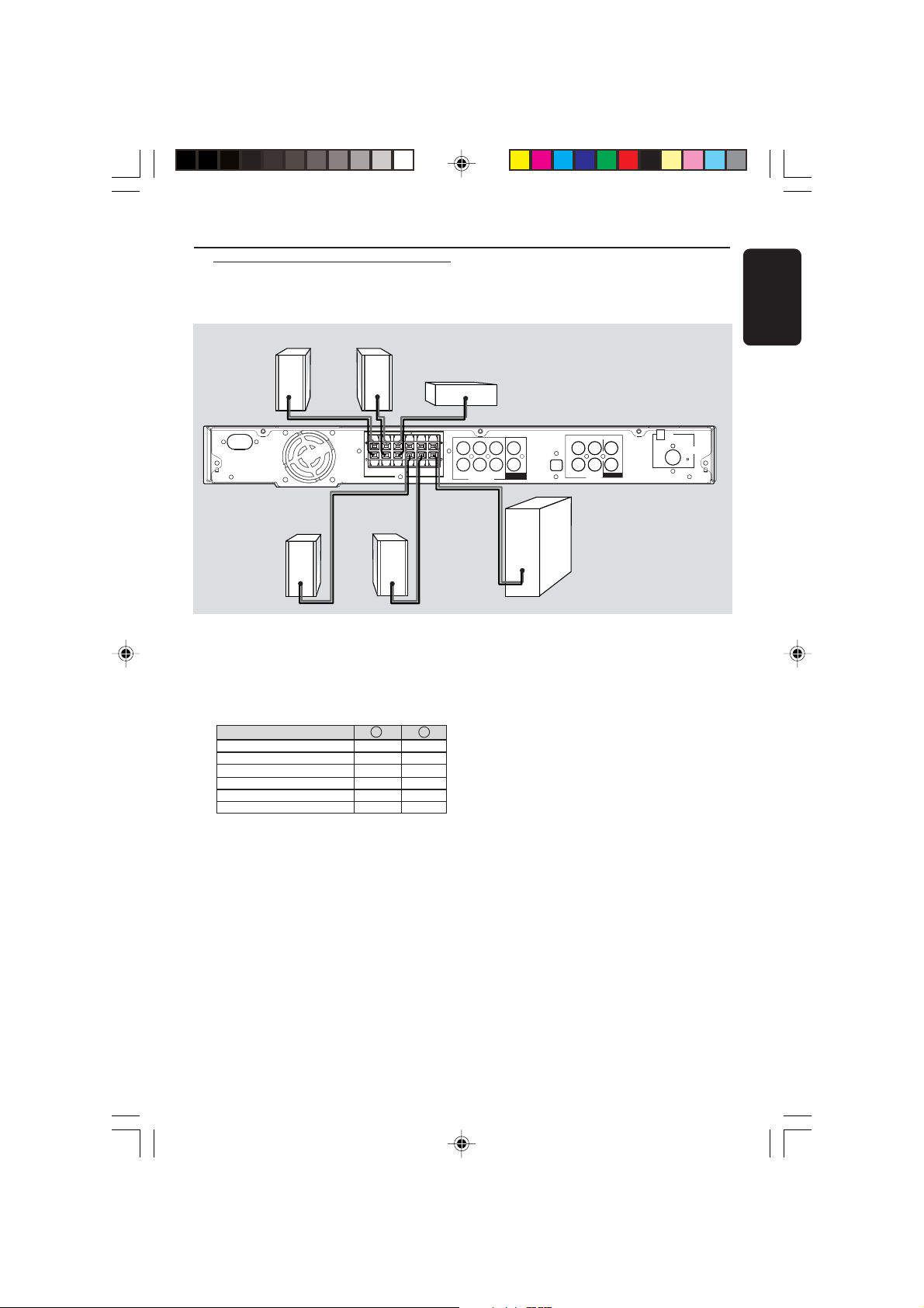
Step 3: Connecting speakers
L
SPEAKERS 3
and subwoofer
Front Right
Front Left
Connections
English
Centre
AC MAINS
SPEAKERS 3
( )
++
FRONT
REAR
REAR
FRONT
FRONT
LEFT
RIGHT
SUB-
RIGHT
LEFT
CENTER
WOOFER
Rear Right Rear Left
● Connect the supplied speaker systems by
matching the colours of the jacks and
speaker cables. Fully insert the stripped
portion of the speaker wire into the
jacks.
Speakers / Subwoofer - +
FRONT LEFT (FL) black white
FRONT RIGHT (FR) black red
FRONT CENTER (FC) black green
REAR LEFT (RL) black blue
REAR RIGHT (RR) black gray
SUBWOOFER (SUBW) black purple
Helpful Hints:
– Ensure that the speaker cables are
correctly connected. Improper connections
may damage the system due to short-circuit.
– Do not connect more than one speaker to
any one pair of +/- speaker jacks.
– Do not connect speakers with an
impedance lower than the speakers supplied.
Please refer to the SPECIFICATIONS section
of this manual.
FRONT LEFT
FRONT RIGHT
SUBWOOFER
6 CHANNEL IN
REAR LEFTFRONT CENTER
REAR RIGHT
COAXIAL IN
COAXIAL OUT
OPTICAL IN
AUX TV
L
R
IN OUT
Subwoofer
MW
ANTENNA
FM
(75 )
AUDIO
7
8239 300 38591
Page 8
L
R
L
Connections
English
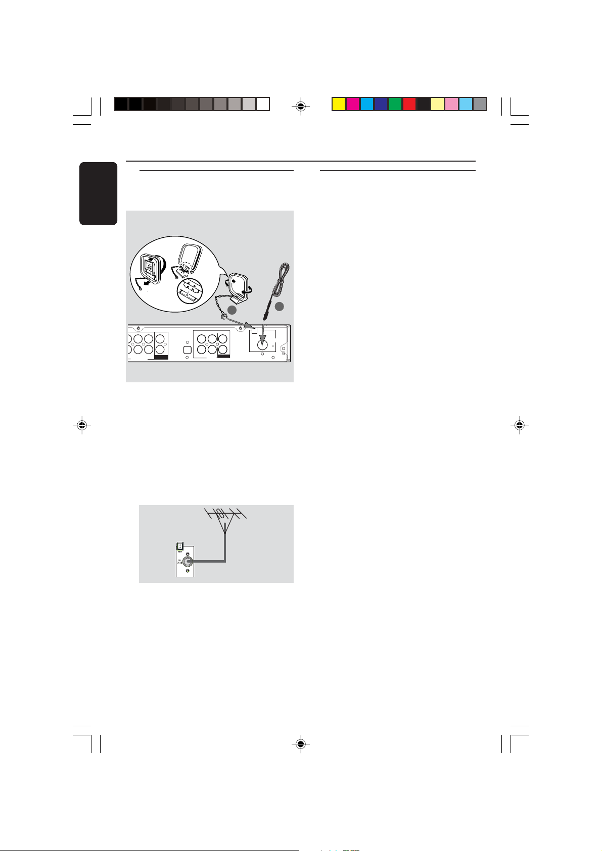
Step 4: Connecting FM/MW
antennas
fix the claw into
the slot
➠
MW
antenna
1
OPTICAL IN
L
R
AUX TV
OUT
IN OUT
AUDIO
EFT
IGHT
SUBWOOFER
6 CHANNEL IN
REAR LEFTFRONT CENTER
REAR RIGHT
COAXIAL IN
COAXIAL OUT
COAXIAL OUT
1 Connect the supplied MW loop antenna
to the MW jack. Place the MW loop
antenna on a shelf or attach it to a stand
or wall.
2 Connect the supplied FM antenna to the
FM jack. Extend the FM antenna and fix
its ends to the wall.
For better FM stereo reception, connect
an external FM antenna (not supplied).
MW
FM
antenna
2
ANTENNA
FM
(75 )
Step 5: Connecting the
power cord
After everything is connected
properly, plug in the AC power cord
to the power outlet.
Never make or change any connections
with the power switched on.
Helpful Hint:
– Refer to the type plate on the rear or
bottom of the system for identification and
supply ratings.
Helpful Hints:
– Adjust the position of the antennas for
optimal reception.
–Position the antennas as far as possible
from your TV, VCR or other radiation source
to prevent unwanted interference.
8
8239 300 38591
Page 9
Optional Connections - Playback
L
SPEAKERS 3
IMPORTANT!
–You can connect other audio and audio/visual equipments to this AV receiver
in order to use the Home Cinema Audio System’s surround sound capabilities.
–For connection to additional components, the audio/video cables are not
supplied.
– When making connections, make sure the colour of cables matches the
colour of jacks.
–Always refer to the instruction manual of the connected equipment to make
an optimal connection.
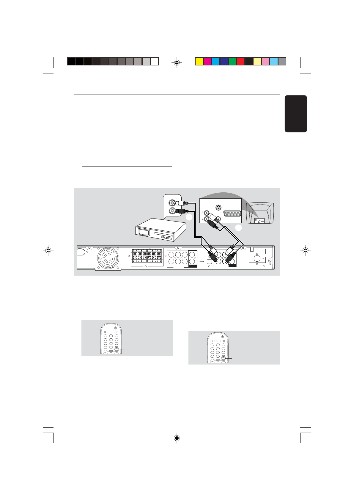
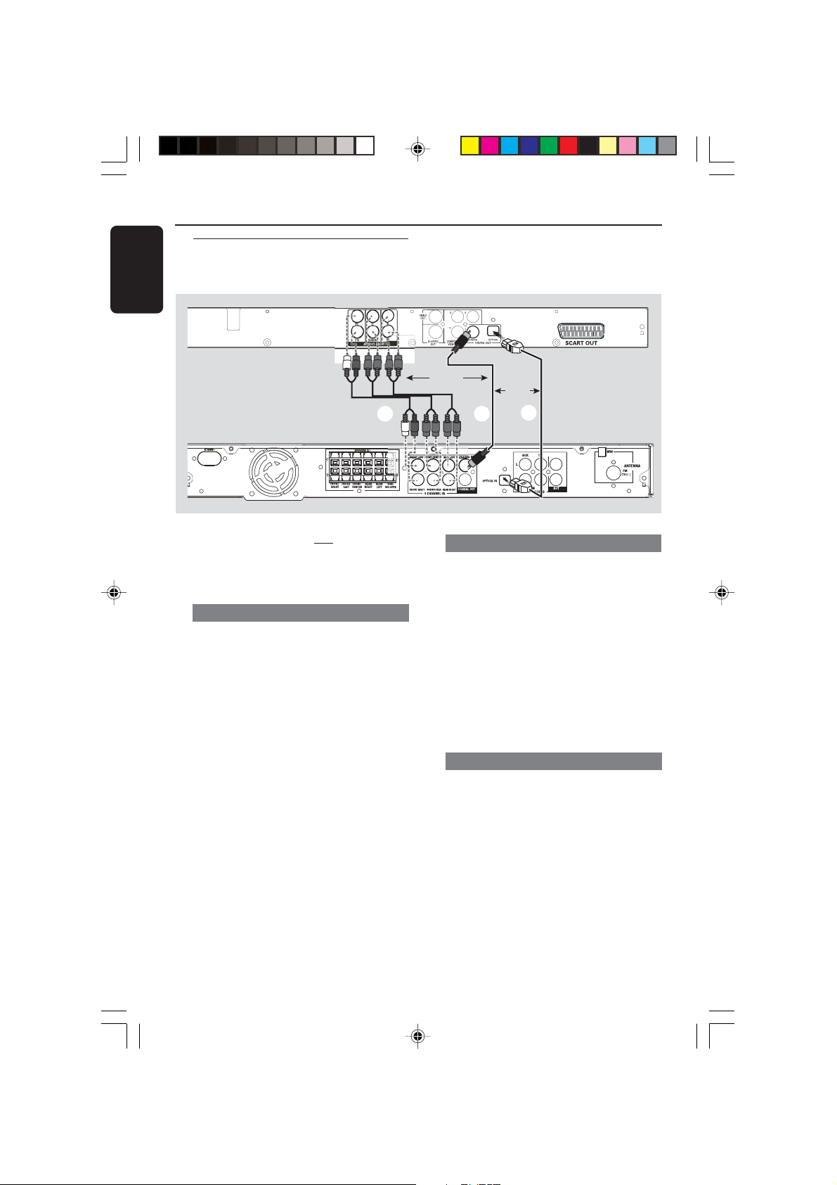
Connecting to TV/VCR/other
audio devices
English
AUDIO OUT
VCR/CD/Tape player
(for example)
ACMAINS ~
SPEAKERS 3
( )
++
FRONT
FRONT
RIGHT
REAR
FRONT
LEFT
SUB-
REAR
CENTER
LEFT
WOOFER
RIGHT
● To hear the TV channels through this AV
receiver, use the audio cables (white/red)
to connect AUDIO IN-TV jacks to the
corresponding AUDIO OUT jacks on the
TV (see fig A).
TV
DISC TUNER AUX
VOL
TV
VOL +-
Before starting operation,
1 Start playing back the connected source
as usual.
2 Press TV on the remote to activate the
input source, then press VOL +- to
adjust the volume level.
L
R
B
AUDIO
OUT
S-VIDEO
IN
VIDEO IN
SCART IN
A
OPTICAL IN
TV/AV
L
R
DISC TUNER AUX
AUX TV
IN OUT
AUDIO
VOL
AUX
VOL +-
FRONT LEFT
REAR LEFTFRONT CENTER
COAXIAL IN
SUBWOOFER
6 CHANNEL IN
REAR RIGHT
COAXIAL OUT
COAXIAL OUT
FRONT RIGHT
● To hear the playback of other audio/visual
devices (such as VCR, MP3 player,
cassette player), use the audio cables
(white/red) to connect AUDIO IN-AUX
jacks to the corresponding AUDIO OUT
jacks on the connected audio device (see
fig B).
Before starting operation,
1 Start playing back the connected source
as usual.
2 Press AUX on the remote to activate
the input source, then press VOL +-
to adjust the volume level.
S-VIDEO
IN
AUDIO
SCART IN
OUT
VIDEO IN
MW
ANTENNA
FM
(75 )
9
8239 300 38591
Page 10
Optional Connections - Playback
English
Connecting to a DVD/SACD
player
DVD/SACD
player
You only need to make
to your DVD/SACD player from the
following options, depending on the
capabilities of your DVD/SACD player.
Option 1: Using 6 Channel In jacks
● If your DVD/SACD player has a built-in
multichannel decoder (e.g. Dolby Digital,
DTS) and has 6-channel (multichannel)
output jacks, you may use the audio
cables (not supplied) to connect the AV
receiver’s 6 CHANNEL IN jacks to the
corresponding output jacks on the
DVD/SACD player (see fig A).
one connection
OR
A B
Option 2: Using Coaxial In jack
● Or, use an coaxial cable to connect the
AV receiver’s COAXIAL IN jack to the
COAXIAL output jack on the
DVD/SACD player (see fig B).
Before starting operation,
1 Start playing back the connected source
as usual.
2 Press DISC on the remote to select
“DISC COAX” in order to activate the
input source, then press VOL +- to
adjust the volume level.
OR
C
Before starting operation,
1 Start playing back the connected source
as usual.
2 Press DISC on the remote to select
“DISC 6CH” in order to activate the
input source, then press VOL +- to
adjust the volume level.
Helpful Hints:
– The audio signals produced by 6 channel is
multichannel surround. Therefore, switching to
Stereo mode has no effect.
– Making recording from this input is not
possible.
10
Option 3: Using Optical In jack
● Or, use an optical fiber-optic cable (not
supplied) to connect the AV receiver’s
OPTICAL IN jack to the OPTICAL
output jack on the DVD/SACD player
(see fig C).
Before starting operation,
1 Start playing back the connected source
as usual.
2 Press DISC on the remote to select
“DISC OPTI” in order to activate the
input source, then press VOL +- to
adjust the volume level.
8239 300 38591
Page 11
Optional Connections - Recording
L
A
SPEAKERS 3
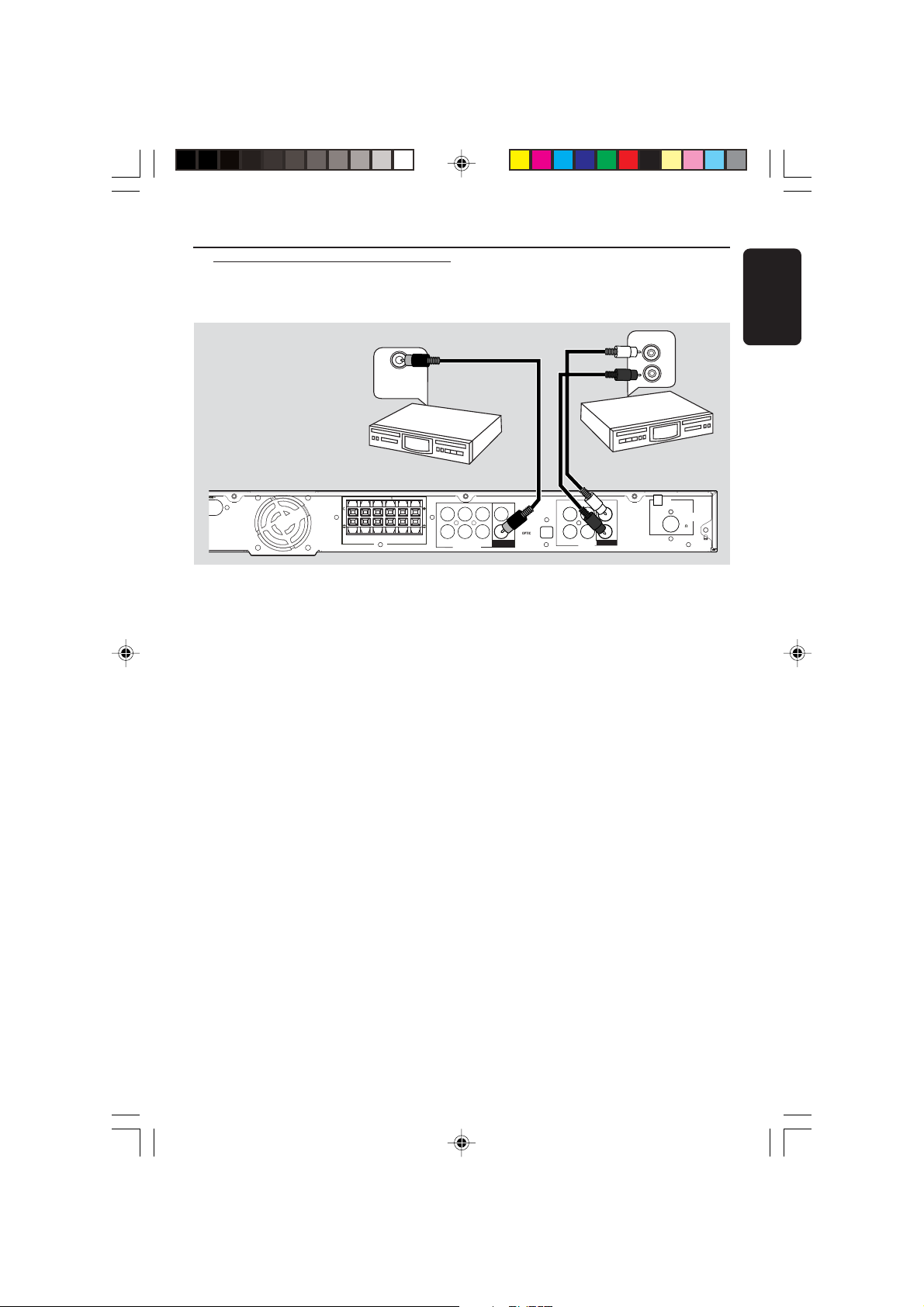
Connecting to a recording
device
COAXIAL IN
/
DIGITAL IN
English
AUDIO IN
L
R
Digital Recording
device
INS~
SPEAKERS 3
( )
+
REAR
FRONT
REAR
FRONT
FRONT
LEFT
RIGHT
SUB-
RIGHT
LEFT
CENTER
WOOFER
● Connect the AV receiver’s COAXIAL
OUT jack to the DIGITAL (COAXIAL)
IN jack on a digital recording device
(DTS-Digital Theatre System compatible,
with a Dolby Digital decoder, for
example).
➜This will allow you to make digital or
analogue recordings from the signals
received from this AV receiver.
AND/OR
● Connect the A V r eceiver’s AUDIO
OUT jacks to the AUDIO IN jacks on an
analogue recording device.
➜This will allow you to make analogue
stereo (two-channel, left and right)
recordings.
Helpful Hints:
– Dolby Digital, DTS or MPEG signal are not
possible to record from this AV receiver.
– Digital recording is not possible when the
digital source material is copy-protected.
Analogue
Recording device
MW
ANTENNA
FM
(75 )
OPTICAL IN
L
R
AUX TV
IN OUT
AUDIO
FRONT LEFT
REAR LEFTFRONT CENTER
SUBWOOFER
6 CHANNEL IN
REAR RIGHT
COAXIAL IN
COAXIAL OUT
COAXIAL OUT
+
FRONT RIGHT
Before starting recording,
1 Press DISC, TUNER, TV or AUX to
select the source you want to record
from.
➜The name of the source appears on
the display panel.
2 Start recording on the external recording
device.
3 Start playback on the connected source
as usual.
Helpful Hints:
– Recording from 6 Channel input source is
not possible.
– The sound settings will not affect the
recording.
11
8239 300 38591
Page 12
Functional Overview
English
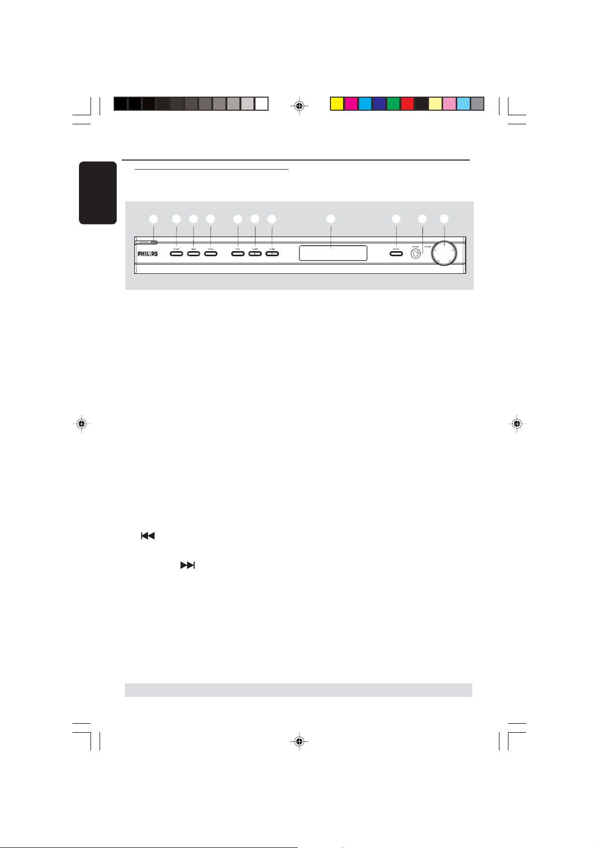
Main unit and remote control
1
2
3
4
5
6
7
1 STANDBY ON (B)
– Switches to standby mode or turns on
the system.
2 SOUND
– Selects a sound effect.
3 BASS
– Selects BASS (low tone) sound mode and
use the VOLUME control to change the
tone level.
4 TREBLE
– Selects TREBLE (high tone) sound mode
and use the VOLUME control to change
the tone level.
5 PROG
– *Enters receiver setup menu.
– TUNER: starts automatic/manual preset
programming.
8
90
!
8 System display panel
9 SOURCE
– Selects the relevant active source mode:
DISC (6CH/COAX/OPTI),
TUNER (FM/MW), AUX or TV.
(on the remote only)
– TV: switches to TV source mode.
–DISC: toggles between DISC 6CH, DISC
COAX and DISC OPTI source mode.
– TUNER: toggles between FM and MW
band.
–AUX: selects AUX mode.
0 PHONES
–Plug in the headphones jack. The
speakers output will be cancelled.
! VOLUME (VOL +-)
– Adjusts the volume level.
– Selects a setting in receiver setup menu.
6 TUNING
–Tunes the radio frequency down.
7TUNING
–Tunes the radio frequency up.
* = Press and hold the button for more than five seconds.
12
8239 300 38591
Page 13
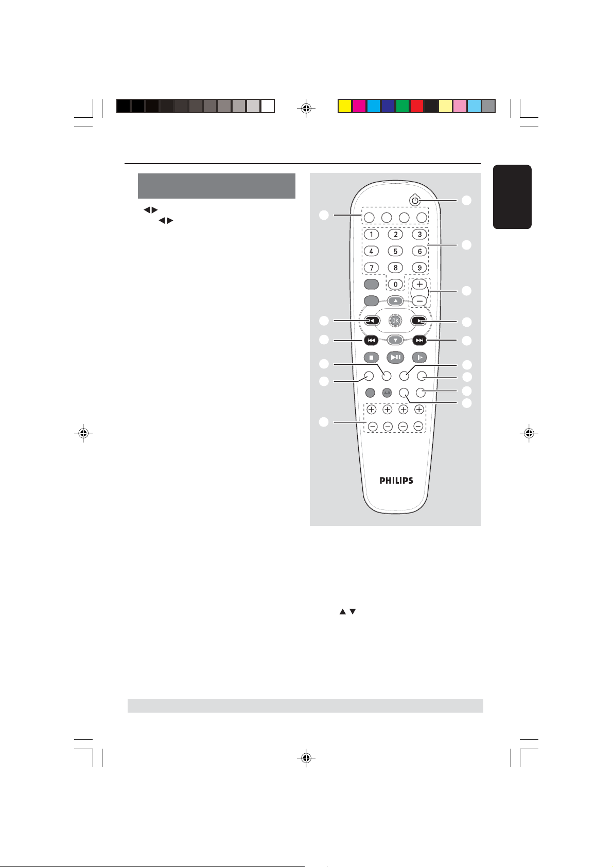
Control buttons available on the
remote only
0
– Use to select a preset radio station.
Functional Overview
TV
5
DISC TUNER AUX
*
English
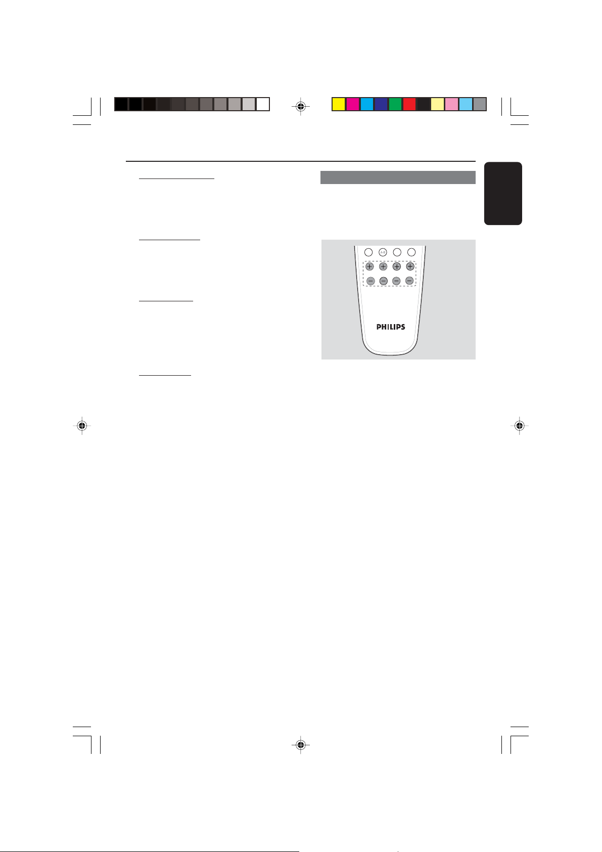
! SURROUND
– Selects multichannel surround or stereo
mode.
@ SUBW +-
– Adjusts subwoofer’s sound level.
REAR +-
– Adjusts rear speakers’ sound level.
CENTER +-
– Adjusts centre speaker’s sound level.
TV VOL +-
– Adjusts TV volume (Philips TV only).
# SLEEP
– Sets the sleep timer function.
$ DIM
– Selects different levels of brightness for
display panel.
% MUTE
– Mutes or restores the volume.
^ NIGHT (in Dolby Digital mode only)
– Optimises for lower-level listening.
& Numeric Keypad (0-9)
– Enters a number of a preset radio station.
* B
– Switches to standby mode.
DISC
DVD MENU
SYSTEM
VOL
0
3
7
!
@
The following keys only operate on a
Philips DVD player. For details, please
refer to a Philips DVD player owner’s
manual
–DVD MENU - DISC
–DVD MENU - SYSTEM
–
–OK
–STOP
– PLAY/PAUSE
– RESUME
– REPEAT
– REPEAT A-B
PLAY/PAUSE
STOP RESUME
SURROUND SOUND NIGHT MUTE
REPEAT REPEAT SLEEP DIM
SUBW REAR CENTER TV VOL
&
9
0
3
^
%
$
#
* = Press and hold the button for more than five seconds.
13
8239 300 38591
Page 14
Getting Started
English
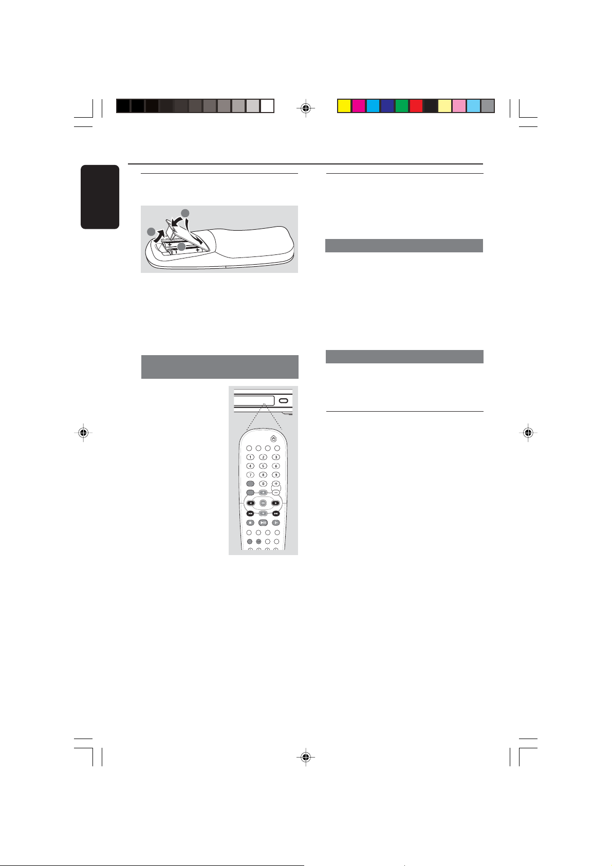
Step 1: Inserting batteries into
the remote control
3
1
2
1 Open the battery compartment.
2 Insert two batteries type R06 or AA,
following the indications (+-) inside
the compartment.
3 Close the cover.
Using the remote control to operate
the system
1 Aim the remote
control directly at the
remote sensor (iR) on
the front panel.
2 Select the source you
wish to control by
pressing one of the
source select buttons
on the remote control
(for example TV,
TUNER).
3 Then select the
desired function (for
example
CAUTION!
– Remove batteries if they are
exhausted or if the remote is not to
be used for a long time.
– Do not use old and new or
different types of batteries in
combination.
– Batteries contain chemical
substances, so they should be
disposed properly.
S, T).
TV
DISC TUNER AUX
DISC
DVD MENU
SYSTEM
PLAY/PAUSE
STOP RESUME
SURROUND SOUND NIGHT MUTE
REPEAT REPEAT SLEEP DIM
Step 2: Switching on/off
After completing all the connections,
connect the AC power cord of the AV
receiver to the wall outlet.
Switching to an active mode
● Press the SOURCE control to select :
DISC 6CH ™ DISC COAX ™
DISC OPTI ™ FM ™ MW™ AUX ™
TV ™ DISC 6CH ....
OR
Press TV, DISC, TUNER or AUX on
the remote.
Switching to standby mode
● Press STANDBY ON (B).
➜The display screen will go blank.
SOUND
Step 3: Setting the speakers
You can adjust the delay times (centre
and rear only) and volume level for
individual speakers. These adjustments
let you optimise the sound according to
your surroundings and setup.
VOL
IMPORTANT!
–Press SURROUND button on the
remote to select Multi-channel
surround mode before adjusting the
speaker settings.
– Set the ‘Test Tone’ to ‘On’ for easy
adjustment.
1 In active mode, press and hold PROG
for five seconds to enter system setup.
2 Press S / T to select one of the
following options : CENTER DELAY,
REAR DELAY, TEST TONE or MENU
OFF.
3 Press PROG to confirm.
14
8239 300 38591
Page 15
Getting Started
REPEAT REPEAT SLEEP DIM
CENTER DELAY – Select this to set
the delay time in relation to the listening
position/distance from the centre
speaker: 5ms, 3ms, 2ms, 1ms or OFF
(default setting).
REAR DELAY – Select this to set the
delay time in relation to the listening
position/distance from the rear speakers :
15ms, 12ms, 9ms, 6ms, 3ms or OFF
(default setting).
TEST TONE – Select this to turn ‘ON’
or ‘OFF’ (default setting) the test tone.
If you have turned on the test tone, the
test signal will be automatically generated
to help you judge the sound level of each
speaker and subwoofer.
MENU OFF – Select this to exit from
the system setup.
4 Use the VOLUME control to adjust the
settings that best suit your surround
sound needs.
➜If the volume control is not used within
5 seconds, it will become normal volume
control function.
5 Press PROG to confirm your selection.
Adjusting the speaker output levels
You can adjust the rear speakers, centre
speaker and subwoofer output levels by
comparing the sound from the front
speakers.
SUBW REAR CENTER TV VOL
● Press the respective buttons on the
remote (REAR +-, CENTER +-
and SUBW +-) to adjust the output
level between -15dB ~ 10dB.
Helpful Hint:
– If you have selected Stereo mode,
adjusting the centre and rear speakers’
volume level will have no effect.
English
Helpful Hints:
– Use the longer delay time settings when
the rear speakers are closer to the listener
than the front speakers.
– If “CHECK SURROUND SETTINGS”
appears on the display, press SURROUND
button to select surround mode.
–“AUTO PROG’” only available for selection
in tuner mode only.
15
8239 300 38591
Page 16

Sound Controls
English
IMPORTANT!
For proper surround sound, make
sure the speakers and subwoofer are
connected (see page 7).
Selecting surround sound
● In DISC COAX or DISC OPTI mode , if
the audio signal received is Dolby Digital
or DTS, pressing SURROUND button
will cyclically go through :
DOLBY DIGITAL / DTS ™ STEREO
● Otherwise, pressing SURROUND
button will cyclically go through :
MOVIE ™ MUSIC ™ PRO LOGIC
™ STEREO
Helpful Hints:
– The available Surround outputs include:
Dolby Digital, DTS (Digital Theatre Systems)
Surround, Dolby Pro Logic II and Dolby Pro
Logic.
–MOVIE and MUSIC are Dolby Pro Logic II
surround sound.
– The surround feature is not available in
DISC 6CH mode.
– The centre and rear speakers operate only
in multichannel surround mode.
– The availability of the various surround
sound modes depends on the number of
speakers used and the sound available on
the disc.
Selecting digital sound effects
Select a preset digital sound effect that
matches your disc’s content or that
optimises the sound of the musical style
you are playing.
● Press SOUND on the remote to select
the available sound effect.
In Dolby Digital, DTS, PRO LOGIC or
PRO LOGIC II (MOVIE) surround mode,
you can select :
DIGIT
SCI-FI
AL
CONCERT, ACTION,DRAMA, or
(default setting)
In PRO LOGIC II (MUSIC) surround
mode or in Tuner mode, you can select :
CLASSIC, ROCK, JAZZ, or
(default setting).
Helpful Hint:
–For flat sound output, select CONCERT or
CLASSIC.
Adjusting the Bass/Treble
level
The BASS (low tone) and TREBLE (high
tone) features enable you to define the
sound-processor settings.
1 Press BASS or TREBLE.
2 Within two seconds, use the VOLUME
control to adjust the Bass or Treble level
(-10dB ~ 10dB, default setting - 0dB).
➜If the volume control is not used
within two seconds, it will resume its
normal volume control function.
➜If headphone is connected, it will
disable the bass/treble controls.
16
8239 300 38591
Page 17
NIGHT
SLEEP
MUTE
PRESET
PROGRAM
Volume Controls and Other Features
Volume control
● Adjust VOLUME control (or press
VOL +/- on the remote) to increase
or decrease the volume level.
➜"VOL MIN" is the minimum volume
level and “VOL MAX” is the maximum
volume level.
For Philips TVs only
● Press TV VOL +/- on the remote
control to adjust the TV’s volume level.
To listen through the headphones
● Plug the headphones to the PHONE
socket at the front of the AV receiver.
➜ The speakers will be muted.
➜The current surround sound will
change to stereo mode.
To turn off the volume temporarily
● Press MUTE on the remote.
➜Playback will continue without sound
MUTE" icon appears.
and "
➜To restore the volume, press MUTE
again or increase the volume level.
Night Mode - turning on/off
When activated the night mode, the high
volume outputs will be softened and low
volume outputs will be brought upward
to an audible level. It is useful for
watching your favourite action movie
without disturbing others at night.
IMPORTANT!
This feature is only available for
movies with Dolby Digital mode.
Dimming system’s display
screen
● In any active mode, press DIM on the
remote to select desired brightness :
HIGH (default setting), MID or LOW.
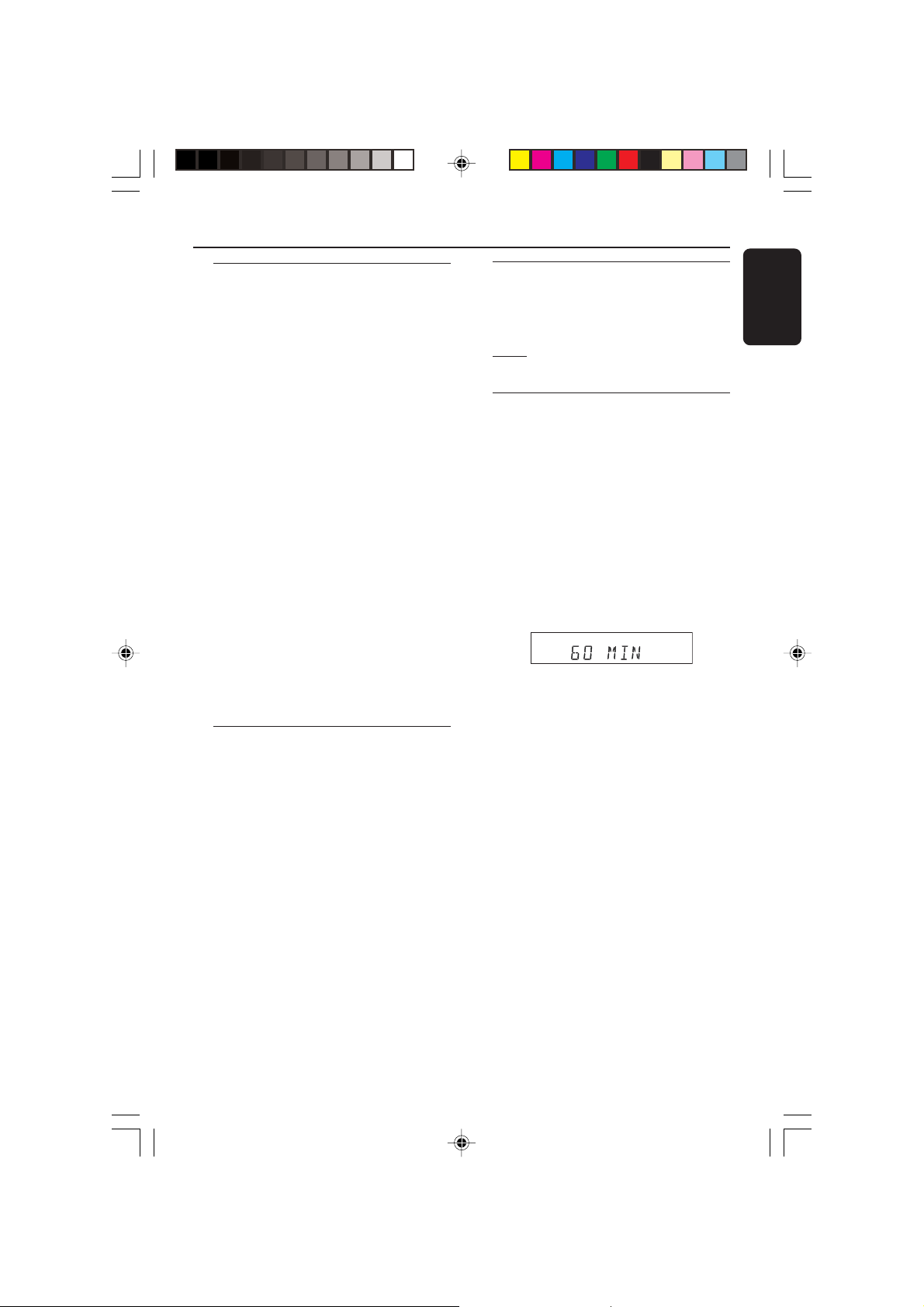
Setting the Sleep Timer
The sleep timer enables the system to
switch to standby mode automatically at a
preset time.
● Press SLEEP on the remote repeatedly
until it reaches the desired preset turn-off
time.
➜The selections are as follows (time in
minutes):
15 ™ 30 ™ 45 ™ 60 ™ 90 ™ 120
™ OFF ™ 15 …
SLEEP” icon will be shown on the
➜ “
display, except if "OFF" is selected.
To check or change the setting
● Press SLEEP once to show the
remaining time before switching off.
If you continue pressing the SLEEP
button, the next Sleep Timer option will
appear.
To cancel the sleep timer
● Press SLEEP repeatedly until "OFF"
appears or press the STANDBY ON
button.
English
● Press NIGHT on the remote repeatedly
to switch the Night mode on or off
(default setting - OFF).
Helpful Hint:
– The night mode option is not available in
DISC 6CH mode.
17
8239 300 38591
Page 18
AUTO PROG
NIGHT
SLEEP
MUTE
PRESET
PROGRAM
TUNER
Tuner Operations
English
IMPORTANT!
Make sure the FM and MW
antennas are connected.
Tuning to radio stations
1
Press TUNER on the remote (or pr ess
SOURCE control on front panel) to
select “FM” or “MW”.
2 Press and hold S / T on the
remote until the frequency indication
starts to change, then release.
➜"FM SEARCH" appears.
➜ The next radio station will be tuned
automatically.
lights up for FM stereo reception.
➜
3 To tune a weak station, press S / T
briefly and repeatedly until an optimal
reception is found.
RDS Function
RDS (Radio Data System) is a
broadcasting service that allows FM radio
stations to send additional information
along with the FM radio. This additional
information includes:
● Frequency
● Station Name
1 In FM mode, if the tuned radio station is
transmitting RDS data, the RDS station
name will be shown on the display panel.
2 Press S / T button to change the
station frequency to get the new RDS
station.
3 If the tuned station is not transmitting an
RDS signal or is not a RDS station, the
display panel will only show the station
frequency.
Helpful Hint:
- RDS function is only available in areas
that support RDS system.
Presetting radio stations
You can store up to 40 preset radio
stations in the memory.
Automatic presetting
You can store all available radio stations
automatically.
1 In tuner mode, press and hold PROG for
five seconds to enter system setup.
2 Press S / T to select “AUTO
PROG”.
3 Press PROG to confirm.
➜“CONFIRM” appears.
4 Press PROG again to start automatic
presetting.
➜“SEARCH” appears.
➜All the available radio stations with
strong transmission signal will be stored.
➜Automatic preset will begin from
preset (1) and all your former presets will
be overridden.
Manual presetting
You can choose to store only your
favourite radio stations.
1 Tune to your desired radio station (see
“Tuning to radio stations”).
2 Press PROG.
PROGRAM” and “PRESET” icons appear.
➜“
3 Use the numeric keypad (0-9) to
select a desired preset number.
PROGRAM” icon goes off before you
➜If “
select the desired preset number, press
PROG button again.
18
8239 300 38591
Page 19

4 Press PROG again to store.
5 Repeat steps 1~4 to store other radio
stations.
Helpful Hints:
– If you attempt to programme more than
40 preset radio stations, “PROG FULL”
appears.
– The system will exit presetting mode if no
button is pressed within two seconds.
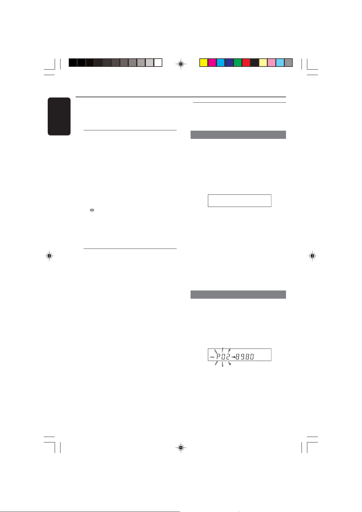
Selecting a preset radio
station
● Press or use the numeric keypad
(0-9) to select a preset number.
➜ The preset number followed by the
radio frequency will appear on the display
panel.
Tuner Operations
English
19
8239 300 38591
Page 20

Tr oubleshooting
English
WARNING
Under no circumstances should you try to repair the system yourself, as this will
invalidate the warranty. Do not open the system as there is a risk of electric shock.
If a fault occurs, first check the points listed below before taking the system for repair. If
you are unable to remedy a problem by following these hints, consult your dealer or
Philips for help.
Problem Solution
No power.
No sound or distorted sound.
There is no sound from the centre and
rear speakers.
Radio reception is poor.
The remote control does not function
properly.
Low hum or buzz sound.
– Check if the AC power cord is properly
connected.
– Adjust the volume.
– Check the speaker connections and settings.
– Disconnect the headphones.
–Press the correct source button on the
remote (TV or AUX, for example) to choose
the equipment that you want to hear through
the AV receiver.
–Press CENTER +- or REAR +- to
adjust the volume level.
– Make sure the centre and rear speakers are
connected correctly.
–Press SURROUND button to select a correct
surround sound setting.
– Make sure the source you are playing is
recorded or broadcast in surround sound
(DTS, Dolby Digital, etc.).
– If the signal is too weak, adjust the antenna or
connect an external antenna for better
reception.
– Increase the distance between the system and
your TV or VCR.
–Tune in to the correct frequency.
– Place the antenna farther away from any
equipment that may be causing the noise.
– Select the source (DISC or TUNER, for
example) before pressing the function button
(S, T).
– Reduce the distance between the remote
control and the system.
– Replace the batteries with new ones.
–Point the remote control directly toward the
IR sensor.
– Check that the batteries are loaded correctly.
– Place the AV receiver as far away as possible
from electrical devices that may be causing
interference.
20
NEED HELP? Visit our website www.philips.com/support
8239 300 38591
Page 21

Specifications
AMPLIFIER SECTION
Total Output Power (Home Theaater Mode)
700W
Total Output Power ( 1% THD)
330W
Front 50W
Centre 50W
Surround 50W1x2
Subwoofer 80W
Frequency Response 150 Hz – 20 kHz / –3 dB
Signal-to-Noise Ratio > 60 dB (CCIR)
Input Sensitivity
- TV In 600 mV
- AUX In 600 mV
- 6 Channel In 800 mV
1 140 Hz – 20 kHz, 3Ω, 1% THD
2 40 Hz – 2 kHz, 3Ω, 1% THD
TUNER SECTION
Tuning Range FM 87.5 – 108 MHz (50 kHz)
26 dB Quieting Sensitivity FM 22 dBf
Signal-to-Noise Ratio FM 55 dB
Harmonic Distortion FM Mono 3%
Frequency Response FM 180 Hz – 10 kHz / ±6 dB
Stereo Separation FM 26 dB (1 kHz)
Stereo Threshold FM 23.5dB
MAIN UNIT
Power Supply Rating 220 – 240 V; 50 Hz
Power Consumption 180 W
Dimensions (w x h x d) 435 mm x 53 mm x 359 mm
Weight 4.00 kg
1
x2
1
2
MW 531 – 1602 kHz (9 kHz)
MW 5 µV/m
MW 40 dB
FM Stereo 3%
MW 5%
SPEAKERS
Front speakers / Rear (surround) speaker
System - Front speaker 2-way, magnetically sheided
- Rear speaker 2-way
Impedance 3 Ω
Speaker drivers 3” full-range woofer, 1”conical
dome tweeter
Frequency response 140 Hz – 20 kHz
Dimensions (w x h x d) 95 mm x 175 mm x 65 mm
Weight 0.66 kg (Front speaker)
0.77 kg (Rear speaker)
CENTRE SPEAKER
System 2-way, magnetically sheided
Impedance 3 Ω
Speaker drivers 3” full-range woofer,1” conical
dome tweeter,
Frequency response 140 Hz – 20 kHz
Power rating 100W
Dimensions (w x h x d) 220 mm x95 mm x 75 mm
Weight 0.8 kg
PASSIVE SUBWOOFER
Frequency response 40 Hz – 2 kHz
Impedance 3 Ω
Subwoofer driver 6.5’’ woofer,
Power rating 100W
Dimensions (w x h x d) 130 mm x 340 mm x 360 mm
Weight 5.11 kg
Specifications subject to change without prior
notice
English
21
8239 300 38591
Page 22

Glossary
English
gue: Sound that has not been turned
Analo
into numbers. Analogue sound varies, while
digital sound has specific numerical values.
These jacks send audio through two channels,
the left and right.
AUDIO OUT Jacks: Jacks on the back of
the AV receiver that send audio to another
system (TV, Stereo, etc.).
Digital: Sound that has been converted into
numerical values. Digital sound is available
when you use the DIGITAL AUDIO OUT
COAXIAL or OPTICAL jacks. These jacks
send audio through multiple channels, instead
of just two channels as analogue does.
Dolby Digital: A surround sound system
developed by Dolby Laboratories capable of
delivering up to 5.1 discrete channels of audio
(front left and right, rear left and right, centre,
and LFE).
Dolby Pro Logic II: It creates five fullbandwidth output channels from two-channel
sources. Decode only systems that derive 5.1
channels instead of the conventional 4
channels of Dolby Pro Logic surround sound.
Dolby Pro Logic Surround: It is a specially
encoded two-channel analogue format that will
produce sound through four speaker channels
(front left, centre, front right, mono surround)
when a Dolby Pro Logic Decoder is used. It is
also compatible with stereo systems but the
user will only have two-channel (front left &
right) of sound.
DTS: Digital Theatre Systems. This is a
surround sound system, but it is different from
Dolby Digital. The formats were developed by
different companies.
Multichannel: DVD is specified to have each
sound track constitute one sound field.
Multichannel refers to a structure of sound
tracks having three or more channels.
Super Audio CD (SACD): This audio
format is based upon the current CD
standards but includes a greater amount of
information that provides higher quality sound.
There are three types of discs: single layer,
double layer and hybrid discs. The hybrid disc
contains both standard audio CD and Super
Audio CD information.
round: A system for creating realistic
Sur
three-dimensional sound fields full of realism
by arranging multiple speakers around the
listener.
Radio Data System, is a broadcasting
RDS:
srvice that allows FM radio stations to send
additional information along with the regular
FM Radio signal. This additional information
including: Frequency and Station Name.
22
8239 300 38591
Page 23

1
DVD Player/ Recorder
DVDR3355
DV
DR3365
User Manual 7
Bedienungsanleitung 63
dvdr3355_cover_15892.indd 1 2005-09-15 3:55:41 PM
Page 24

2 3
Important notes for users in the
U.K.
Mains plug
This apparatus is fitted with an approved 13
Amp plug. To change a fuse in this type of plug
proceed as follows:
1 Remove fuse cover and fuse.
2 Fix new fuse which should be a BS1362
5 Amp, A.S.T.A. or BSI approved type.
3 Refit the fuse cover.
If the fitted plug is not suitable for your socket
outlets, it should be cut off and an appropriate
plug fitted in its place.
If the mains plug contains a fuse, this should
have a value of 5 Amp. If a plug without a fuse
is used, the fuse at the distribution board
should not be greater than 5 Amp.
Note: The severed plug must be disposed of to
avoid a possible shock hazard should it be
inserted into a 13 Amp socket elsewhere.
How to connect a plug
The wires in the mains lead are coloured with
the following code: blue = neutral (N),
brown = live (L).
As these colours may not correspond with the
colour markings identifying the terminals in your
plug, proceed as follows:
– Connect the blue wire to the terminal
marked N or coloured black.
– Connect the brown wire to the terminal
marked L or coloured red.
– Do not connect either wire to the earth
terminal in the plug, marked E (or ˛) or
coloured green (or green and yellow).
Before replacing the plug cover, make certain
that the cord grip is clamped over the sheath of
the lead - not simply over the two wires.
Copyright in the U.K.
Recording and playback of material may require
consent. See Copyright Act 1956 and The
Performer’s Protection Acts 1958 to 1972.
Norge
Typeskilt finnes på apparatens underside.
Observer: Nettbryteren er sekundert
innkoplet. Den innebygde netdelen er
derfor ikke frakoplet nettet så lenge
apparatet er tilsluttet nettkontakten.
For å redusere faren for brann eller elektrisk
støt, skal apparatet ikke utsettes for regn
eller fuktighet.
Italia
DICHIARAZIONE DI CONFORMITA’
Si dichiara che l’apparecchio DVDR3355/
DVDR3365, Philips risponde alle prescrizioni
dell’art. 2 comma 1 del D.M. 28 Agosto 1995
n. 548.
Fatto a Eindhoven
Philips Consumer Electronics
Philips, Glaslaan 2
5616 JB Eindhoven, The Netherlands
For Customer Use:
Read carefully the information located at
the bottom or rear of your DVD Recorder
and enter below the Serial No. Retain this
information for future reference.
Model No. DVD RECORDER
DVDR3355 / DVDR3365
Serial No. _______________
dvdr3355_cover_15892.indd 2 2005-09-15 3:55:42 PM
Page 25
CAUTION
VISIBLE AND INVISIBLE LASER
RADIATION WHEN OPEN AVOID
EXPOSURE TO BEAM
ADVARSEL
SYNLIG OG USYNLIG LASERSTRÅLING
VED ÅBNING UNDGÅ UDSÆTTELSE
FOR STRÅLING
VARNING
SYNLIG OCH OSYNLIG
LASERSTRÅLNING NÄR DENNA DEL
ÄR ÖPPNAD BETRAKTA EJ STRÅLEN
VARO!
AVATTAESSA OLET ALTTIINA
NÄKYVÄLLE JA NÄKYMÄTTÖMÄLLE
LASER SÄTEILYLLE. ÄLÄ KATSO
SÄTEESEEN
VORSICHT
SICHTBARE UND UNSICHTBARE
LASERSTRAHLUNG WENN
ABDECKUNG GEÖFFNET NICHT DEM
STRAHL AUSSETSEN
ATTENTION
RAYONNEMENT LASER VISIBLE ET
INVISIBLE EN CAS D’OUVERTURE
EXPOSITION DANGEREUSE AU
FAISCEAU
DK
Advarsel: Usynlig laserstråling ved åbning
når sikkerhedsafbrydere er ude af funktion.
Undgå utsættelse for stråling.
Bemærk: Netafbryderen er sekundært
indkoblet og ofbryder ikke strømmen fra
nettet. Den indbyggede netdel er derfor
tilsluttet til lysnettet så længe netstikket
sidder i stikkontakten.
S
Klass 1 laseraparat
Varning! Om apparaten används på annat
sätt än i denna bruksanvisning specificerats,
kan användaren utsättas för osynlig
laserstrålning, som överskrider gränsen för
laserklass 1.
Observera! Stömbrytaren är sekundärt
kopplad och bryter inte strömmen från
nätet. Den inbyggda nätdelen är därför
ansluten till elnätet så länge stickproppen
sitter i vägguttaget.
SF
Luokan 1 laserlaite
Varoitus! Laitteen käyttäminen muulla kuin
tässä käyttöohjeessa mainitulla tavalla
saattaa altistaa käyttäjän
turvallisuusluokan 1 ylittävälle
näkymättömälle lasersäteilylle.
Oikeus muutoksiin varataan. Laite ei saa
olla alttiina tippu-ja roiskevedelle.
Huom. Toiminnanvalitsin on kytketty
toisiopuolelle, eikä se kytke laitetta irti
sähköverkosta. Sisäänrakennettu verkko-osa
on kytkettynä sähköverkkoon aina silloin,
kun pistoke on pistorasiassa.
dvdr3355_cover_15892.indd 3 2005-09-15 3:55:42 PM
Page 26
4 5
dvdr3355_cover_15892.indd 4 2005-09-15 3:55:42 PM
Page 27

English
Deutsch
LASER
Type Semiconductor laser
InGaAlP (DVD)
AIGaAs (CD)
Wave length 658 nm (DVD)
790 nm (CD)
Output Power 30 mW (DVD+RW write)
1.0 mW (DVD read)
1.0 mW (CD read)
Beam divergence 84 degrees (DVD)
61 degrees (CD)
‘CONSUMERS SHOULD NOTE THAT NOT ALL HIGH
DEFINITION TELEVISION SETS ARE FULLY
COMPATIBLE WITH THIS PRODUCT AND MAY CAUSE
ARTIFACTS TO BE DISPLAYED IN THE PICTURE. IN
CA
SE OF 525 OR 625 PROGRESSIVE SCAN PICTURE
PROBLEMS, IT IS RECOMMENDED THAT THE USER
SWITCH THE CONNECTION TO THE ‘STANDARD
DEFINITION’ OUTPUT. IF THERE ARE QUESTIONS
REGARDING OUR TV SET COMPATIBILITY WITH THIS
MODEL 525p AND 625p DVD PLAYER, PLEASE
CONTACT OUR CUSTOMER SERVICE CENTER.’
Index
English ------------------------------------------ 7
Deutsch ---------------------------------------63
This product complies with the
radio interference requirements of
the European Community.
This product complies with
the requirements of the
following directives and
guidelines: 73/23/EEC +
89/336/EEC + 93/68/EEC
Disposal of your old product
Your product is designed and manufactured with high quality materials
and components, which can be recycled and reused.
When this crossed-out wheeled bin symbol is attached to a product it
means the product is covered by the European Directive 2002/96/EC.
Please inform yourself about the local separate collection system for
electrical and electronic products.
Please act according to your local rules and do not dispose of your old products with
your normal household waste. The correct disposal of your old product will help
prevent potential negative consequences for the environment and human health.
Disposal of your old product
Your product is designed and manufactured with high quality materials
and components, which can be recycled and reused.
When this crossed-out wheeled bin symbol is attached to a product it
means the product is covered by the European Directive 2002/96/EC.
Please inform y
ourself about the local separate collection system for
electrical and electronic products.
Please act according to your local rules and do not dispose of your old products with
your normal household waste. The correct disposal of your old product will help
prevent potential negative consequences for the environment and human health.
Se débarrasser de votre produit usagé (Fr ançais)
Votre produit est conçu et fabriqué avec des matériaux et des
composants de haute qualité, qui peuvent être recyclés et utilisés de
nouveau
.
Lorsque ce symbole d'une poubelle à roue barrée est attaché à un
produit, cela signifie que le produit est couver t par la Directive
Européenne 2002/96/EC.
Veuillez vous informer du système local de séparation des déchets
électriques et électroniques.
Veuillez agir selon les règles locales et ne pas jeter vos produits usagés avec les déchets
domestiques usuels. Jeter correctement votre produit usagé aidera à prévenir les
conséquences négatives potentielles contre l'environnement et la santé humaine.
Cómo deshacerse del producto usado (Español)
Su producto ha sido diseñado y fabricado con materiales y componentes de
alta calidad, que pueden ser reciclados y reutilizados.
Cuando vea este símbolo de una papelera con ruedas tachada junto a un
producto,
esto significa que el producto está bajo la Directiva Europea
2002/96/EC
Deberá informarse sobr
e el sistema de reciclaje local separado para
productos eléctricos y electrónicos.
Siga las normas locales y no se deshaga de los productos usados tirándolos en la basura
normal de su hogar. El reciclaje correcto de su producto usado ayudará a evitar
consecuencias negativas para el medio ambiente y la saludde las persona.
Entsorgung Ihres Altgerätes (Deutsch)
Ihr Produkt ist aus hochqualitativen Materialien und Bestandteilen hergestellt,
die dem Recycling zugeführt und wiederverwertet werden können.
Falls dieses Symbol eines durchgestrichenen Müllcontainers auf Rollen auf
diesem Produkt angebracht ist, bedeutet dies, dass es von der Europäischen
Richtlinie 2002/96/EG erfasst wird.
Bitte informieren Sie sich über die örtlichen Sammelstellen für Elektroprodukte
und elektronische Geräte
.
Bitte beachten Sie die lokalen Vorschriften und entsorgen Sie Ihre Altgeräte nicht mit dem
normalen Haushaltsmüll. Die korrekte Entsorgung Ihres Altgerätes ist ein Beitrag zur
Vermeidung möglicher negativer Folgen für die Umwelt und die menschliche Gesundhei.
dvdr3355_cover_15892.indd 5 2005-09-15 3:55:44 PM
Page 28

6
This product incorporates copyright
protection technology that is
protected by US patents and other
intellectual property rights. Use of this
copyright protection technology must
be authorized by Macrovision, and is
intended for home and other limited
viewing uses only unless otherwise
authorized by Macrovision. Reverse
engineering or disassembly is
prohibited.
U.S. Patent Numbers 4,631,603;
4,819,098; 4,907,093; 5,315,448 and
6,516,132.
Manufactured under license from
Dolby Laboratories. “Dolby” and the
double-D symbol are trademarks of
Dolby Laboratories.
DivX®, DivX Certified, and associated
logos are trademarks of
DivXNetworks, Inc and are used under
license.
This connection is also known as
‘FireWire’ and ‘IEEE 1394.’ This
connection is used for the transfer of
high bandwidth digital signals as used
by digital video (DV) camcorders.
Audio and video signals are
transmitted using a cable.
This is a simple programming system for
DVD recorders. To use it, enter the
programming number associated with your
television programme. You can find this
number in your favourite listings magazine.
SHOWVIEW® is a registered trademark of
Gemstar Development Corporation.
SHOWVIEW® is manufactured under license
from Gemstar Development Corporation.
Ein einfaches Programmiersystem für DVDRecorder. Zur Verwendung wird die zum
Fernsehprogramm angegebene
Programmiernummer eingegeben. Diese
Nummer wird auch in vielen
Programmzeitschriften vermerkt.
S
HOWVIEW
®
ist eine eingetragene Marke der
Gemstar Development Corporation.
SHOWVIEW® wird unter der Lizenz von
Gemstar Development Corporation
hergestellt.
dvdr3355_cover_15892.indd 6 2005-09-15 3:55:46 PM
Page 29

English
7
What kind of disc should I use for
recording?
You can only record on a DVD+R and
DVD+RW discs. DVD+R/+RW is the most
compatible recordable DVD format on the
market today. They are fully compatible to
most of the existing DVD-Video players and
DVD-ROM drives in computers.
What is the capacity of a DVD+R/+RW
disc?
4.7GB, or equivalent to 6CDs. You can store
only one hour of recordings on a single disc at
the highest quality (DVD standard) and about
6 hours recordings at the lowest quality (VHS
standard).
The recording mode indicates the number of
hours that will fit on a single disc.
What is the difference between DVD+R
and DVD+RW?
DVD+R is “recordable” and DVD+RW is
“erasable” and “rewritable”. With a DVD+R,
you can record multiple sessions on the same
disc, but when the disc is full, you cannot
record any more on the disc. The DVD+RW
allows you to record over the same disc
literally hundreds of times.
What is DV?
Using DV, also known as i.LINK, you can
connect a DV-equipped camcorder to this
recorder using a single DV cable for input and
output of audio, video, data and control
signals.
– This recorder is only compatible with DVformat (DVC-SD) camcorders. Digital satellite
tuners and Digital VHS video recorders are
not compatible.
– You cannot connect more than one DV
camcorder at a time to this recorder.
– You cannot control this recorder from
external equipment connected via the DV IN
socket.
Can I copy a VHS tape or DVD from an
external player?
Yes, but only if the VHS tape or DVD is not
copy protected.
What are Titles and Chapters?
A DVD disc contains Titles and Chapters,
which are similar to the Titles and Chapters of
a book. A Title is often a complete movie and
is broken down into Chapters, or individual
scenes from the movies.
Title
Chapter
Title
Chapter Chapter Chapter Chapter
chapter markers
Programmes are recorded as a single title, it
may consist of one chapter or a few chapters
within a title, depending on the recording
settings.
How do I set up Titles and Chapters?
The DVD recorder automatically creates a
new Title every time you start a new
recording. You can then add Chapters to these
recordings manually or have them
automatically inserted at 5-minutes intervals.
What does “finalising” a disc do?
Finalising a disc locks the disc so it can no
longer be recorded, only required for DVD+R.
It will then be compatible with virtually any
DVD player. To close a disc without finalising
it, simply stop recording and eject the disc.
You will still be able to record on the disc if
there is room for more recordings.
How good is the quality of the
recording?
There are a few quality levels to choose from,
ranging from “1 hour mode” (High Quality) to
“6 hours mode” (VHS quality). Press REC
MODE button on the remote control to
choose the quality level that best suits your
purpose and the length of material.
Record
Mode
Picture Quality
Maximum Recording
Time per Disc
1 Hour Mode
2 Hour Mode
4 Hour Mode
6 Hour Mode
High quality
DV
D quality-Standard Play
VHS quality-Extended Play
VHS quality-Super Long Play
1 hour
2 hours
4 hours
6 hours
Frequently Asked Questions
1_dvdr3355_eu_eng_15891.indd 7 2005-04-27 2:35:21 PM
Page 30

English
8
9
Contents
Frequently Asked Questions .......... 7
Care and Safety Information
Setup ...........................................................
10
Cleaning discs ...........................................
10
About recycling ........................................
10
General Informatio
n
Introduction ...............................................11
Accessories supplied ................................
11
Region codes ..............................................
11
Basic Connections - DVD recorder
Step 1: Connecting the antenna
cables ...........................................................
12
Step 2: Connecting the video cable .....
13
Option 1: Using Scart socket
(best picture quality) ...................................
13
Option 2: Using S-Video socket
(excellent picture quality) ..........................13
Option 3: Using Video (CVBS) socket
(good picture quality) .................................
13
Step 3: Connecting the audio cables ...14
Option 1: Using Audio sockets ................14
Option 2: Using Coaxial socket ...............
14
Optional Connections
Connecting to a Cable Box or
Satellite Receiver ......................................
15
Connecting to a VCR or other
similar device .............................................
16
Connecting to a VCR and Cable Box/
Satellite Receiver ......................................
17
Connecting a camcorder to the front
sockets ........................................................
18
Option 1: Using DV IN socket .................18
Option 2: Using S-VIDEO In or
VIDEO In socket ..........................................
18
Connecting a USB flash drive or USB
memory card reader ................................
19
Remote Control
(DVDR3365
) ......................................20~21
Remote Control
(DVDR3355) ......................................
22~23
Main Uni
t
Sockets behind the flap ..............................24
Getting Started
Step 1: Inserting Batteries .....................
25
Using the remote control to operate
the system ......................................................
25
Step 2: Setting the TV ............................ 25
Step 3: Select the country of your
residence ....................................................
26
Step 4: TV channel programming ........
26
Automatic TV channel search ..................26
Modifying Channel Information ...............
27
Sorting the TV channels .............................28
Step 5: Setting the language .................. 28
Step 6: Setting the time & date ............
29
Recordin
g
Discs for recording .................................. 30
Recording settings ...................................
30
Auto Chapter Markers ...............................31
Default Source ..............................................31
Default Recording Mode ............................
31
Manual recording ..................................... 32
One Touch Recording - automatic
turn-off .......................................................
32
About timer recording ...........................
33
Timer recording (manually) ...........
33~34
Setting a timer recording from an external
Cable Box/Satellite Receiver ....................34
Timer recording (SHOWVIEW®
System) .......................................................
35
Changing/ Deleting a timer
recording ....................................................
36
Simultaneous recording and
playback ......................................................
36
Editing/Finalising Recordin
g
About Disc editing ...................................
37
Accessing disc editing menu ..................
37
Rename disc ...................................................38
Erase disc (DVD+RW only) ......................
38
Record new title ...........................................
38
Overwrite disc (DVD+RW only) ............38
Make compatible (DVD+RW only) ........
39
Lock/Unlock disc (DVD+RW only) .......
39
Playing your recordings (DVD+R) on
other DVD players ..................................
39
About title editing ...................................
40
1_dvdr3355_eu_eng_15891.indd 8 2005-04-27 5:03:25 PM
Page 31

English
9
Contents
Accessing title editing menu ................. 40
Video editing ................................................ 40
Rename title ..................................................
41
Erase title .......................................................
41
Overwrite title (DVD+RW only) ...........
41
Overwrite from the selected title ..........
41
Append recording ........................................
41
About video editing ................................. 42
Accessing video editing menu ..............
42
Selecting a title ..............................................43
Selecting a chapter .......................................
43
Creating chapter marker ...........................43
Hiding an unwanted chapter ....................
44
Changing Index Picture .............................
44
Splitting a title (DVD+RW only) ............ 44
Playback
Playable discs .............................................
45
Inserting a disc ..........................................
45
Starting disc playback .............................
46
Playing a DVD video disc ...........................46
Playing a (Super) Video CD .......................46
Playing an audio CD ....................................
46
Playing a DVD+R/+RW disc .....................47
Playing a DivX disc .......................................
47
Playing an MP3 disc ......................................
47
Playing a picture disc (or musical slide
show) ..............................................................
48
Playing from a USB flash drive /USB
memory card reader ..................................
48
Advance Playback Features
Changing to another title/chapter/
track ............................................................
49
Pausing playback and step play .............
49
Searching forwards/backwards ............
49
Using T/C options ...................................
50
Selecting various repeat/shuffle
functions .........................................................50
Programming disc tracks ............................
51
Changing the audio soundtrack
language ..........................................................
51
Changing subtitle language ........................
52
Switching camera angles .............................52
Time search ...................................................
52
DVD System Menu Options
Accessing System Menu - General ......
53
Screen Saver ..................................................53
Country ..........................................................
53
Video Output Format .................................
54
Restore Factory settings ............................
54
Accessing System Menu -Playback ...... 55
TV Aspect Ratio ...........................................55
Parental rating level .....................................
56
Setting or changing the password ...........
57
Digital Audio Output ..................................57
Accessing System Menu - Record ....... 58
Accessing System Menu - Language ....
58
Accessing System Menu - Channel
Setup ...........................................................
58
Accessing System Menu - Clock ..........
58
Date and Time ..............................................58
Show DivX
®
registration code .................58
Specifications ........................................59
Troubleshooting ..........................
60~61
Glossary ...................................................
62
1_dvdr3355_eu_eng_15891.indd 9 2005-04-27 5:03:25 PM
Page 32

English
10
11
Cleaning discs
Some problems occur because the disc
inside the recorder is dirty (frozen picture,
sound disruptions, picture distortions). To
avoid these problems, discs should be
cleaned on a regular basis.
To clean a disc, use a micro fibre cleaning
cloth and wipe the disc from the center
to the edge in a straight line.
CAUTION!
Do not use solvents such as
benzene, thinner, commercially available
cleaners, or anti-static sprays intended
for analog discs.
Since the optical unit (laser) of the DVD
recorder operates at a higher power than
regular DVD or CD players, cleaning
CDs intended for DVD or CD players
may damage the optical unit (laser).
Therefore, refrain from using a cleaning
CD.
About recycling
These operating instructions have been
printed on non-polluting paper. This
electronic equipment contains a
large number of materials that can be
recycled. If you are disposing of an old
machine, please take it to a recycling
center. Please observe the local
regulations regarding disposal of
packaging materials, exhausted batteries,
and old equipment.
Care and Safety Information
CAUTION!
High voltage! Do not open
the device. You run the risk of
getting an electric shock.
The machine does not contain
any user-serviceable parts. Please
leave all maintenance work to
qualified personnel.
Setup
Finding a suitable location
– Place the set on a flat, hard and stable
surface. Do not place the set on a carpet.
– Do not position the set on top of
other equipment that might heat it up
(e.g., receiver or amplifier).
– Do not put anything under the set (e.g.,
CDs, magazines).
Space for ventilation
– Place the apparatus in a location with
adequate ventilation to prevent internal
heat build up. Allow at least 10 cm (4.5”)
clearance from the rear and the top of
the set and 5cm (2.3”) from the left and
right to prevent overheating.
10cm (4.5")
10cm (4.5")
5cm (2.3")
5cm (2.3")
Avoid high temperatures, moisture,
water and dust
– Apparatus shall not be exposed to
dripping or splashing.
– Do not place any sources of danger on
the apparatus (e.g., liquid filled objects,
lighted candles).
1_dvdr3355_eu_eng_15891.indd 10 2005-04-27 2:35:23 PM
Page 33

English
11
General Information
Introduction
Your Philips DVD recorder allows you to
record the TV programmes or duplicate
camcorder recordings to a DVD+RW or
DVD+R and play pre-recorded DVDs.
The recordings you make on the
Recorder will play on most of the DVD
players and DVD-ROM drives. The
DVD+R discs have to be finalised before
they can be played on other DVD players.
Please take time to read this user manual
before using your DVD recorder. It
contains important information and notes
regarding operation.
Helpful Hints:
– If you have questions or if problems come
up during operation, please see the chapter
‘Troubleshooting’.
– If you need further assistance, please call
the customer support service for your
country. The corresponding telephone
numbers and e-mail addresses are given in
the guarantee booklet.
Accessories supplied
– Remote control and batteries
– Scart cable
– RF coaxial cable
– Quick Use Guide
Region codes
DVD films are usually not released at the
same time in all regions of the world,
thus all DVD players are keyed to a
specific region code.
This device will only play
Region 2 DVDs or DVDs
manufactured to be played in
all regions (‘ALL’). DVDs from
other regions cannot be
played on this DVD recorder.
ALL
2
1_dvdr3355_eu_eng_15891.indd 11 2005-04-27 2:35:26 PM
Page 34

English
12
13
Basic Connections - DVD recorder
AUDIO
OU
T
S-VIDEO
IN
VIDEO IN
TV
A
B
VCR/Cable Box/
Satellite Receiver
Antenna/
cable TV signal
Step 1: Connecting the
antenna cables
These connections enable you to
watch and record TV programmes using
the DVD recorder. If the antenna signal is
connected via a VCR, Cable Box or
Satellite Receiver, ensure that
these devices are turned on in order to
watch or record the cable programmes.
If you want to connect to a VCR
and/or Cable Box/Satellite Receiver,
see page 15~17 for the complete
connection to your TV.
A Connect existing Antenna/Cable TV
signal (or from the Cable Box/Satellite
Receiver {RF OUT or TO TV}) to the
ANTENNA socket on the DVD
recorder.
B Use the supplied RF coaxial cable to
connect TV socket on the DVD
recorder to the antenna input socket on
your TV (VHF/UHF RF IN).
TIPS: Before making or changing any connections, make sure that all the devices are disconnected
from the power outlet.
1_dvdr3355_eu_eng_15891.indd 12 2005-04-27 2:35:30 PM
Page 35

English
13
Basic Connections - DVD recorder (continued)
OR
OR
Step 2: Connecting the
video cable
This connection enables you to view the
disc playback from the DVD recorder.
You only need to choose one of the
options below to make your video
connection.
Option 1: Using Scart socket (best
picture quality)
Use the scart cable to connect EXT1
TO TV-I/O socket on the DVD
recorder to the corresponding SCART
input socket on the TV.
Helpful Hints:
– If your TV set has several SCART sockets,
select SCART socket that is suitable for both
video output and video input.
– If your TV set display a selection for the
SCART socket, select ‘VCR’ as the source for
the SCART socket.
– The EXT2 AUX-I/O socket is intended
only for additional devices.
Option 2: Using S-Video socket
(excellent picture quality)
Use an S-video cable (not supplied) to
connect S-VIDEO (Y/C) socket on the
DVD recorder to the S-Video input
socket (or labelled as Y/C or S-VHS) on
the TV.
Option 3: Using Video (CVBS)
socket (good picture quality)
Use a composite video cable (yellow -
not supplied) to connect VIDEO
(CVBS) socket on the DVD recorder to
the video input socket (or labelled as
A/V In, Video In, Composite or
Baseband) on the TV.
AUDIO
OU
T
S-VIDEO
IN
VIDEO IN
TV
Option 1
Option 2
Option
3
TIPS: Before making or changing any connections, make sure that all the devices are disconnected
from the power outlet.
1_dvdr3355_eu_eng_15891.indd 13 2005-04-27 2:35:34 PM
Page 36

English
14
15
Basic Connections - DVD recorder (continued)
STEREO / TV
DIGITAL IN
Option 2
Option 1
OR
AV amplifier/
receiver
Step 3: Connecting the
audio cables
This connection enables you to listen to
the sound. This connection is not
required if the DVD recorder is
connected to the TV using scart cable.
Option 1: Using Audio sockets
You can connect the DVD recorder to a
two channel stereo system or receiver in
order to enjoy the stereo sound system.
Use an audio cables (red/white ends - not
supplied) to connect AUDIO L/R
sockets to one of the following devices
with the same input sockets.
– a stereo system (for example, TV or
mini system).
– a receiver with two channel analog
stereo.
Option 2: Using Coaxial socket
You can connect the DVD recorder to
an AV amplifier/receiver in order to
enjoy multichannel surround sound.
Use a coaxial cable (not supplied) to
connect COAXIAL socket to the device
that has the same input socket
(COAXIAL IN or DIGITAL IN).
– an AV amplifier/receiver with a digital
multi-channel sound decoder.
Before you start operating, set the Digital
Audio Output accordingly (see page 57).
If the Digital Output setting does not
match your stereo’s capabilities, the
stereo may produce a strong, distorted
sound or no sound at all.
TIPS: Before making or changing any connections, make sure that all the devices are disconnected
from the power outlet.
1_dvdr3355_eu_eng_15891.indd 14 2005-04-27 2:35:38 PM
Page 37

English
15
Optional Connections
A
B
C
Antenna/ cable
TV signals
Connecting to a Cable Box or
Satellite Receiver
Option 1
If your Cable Box/Satellite Receiver
has only an antenna output socket
(RF OUT or TO TV),
refer to “Connecting the antenna cables”
on page 12 for the complete connection
to your TV.
Option 2
If your Cable Box/Satellite Receiver
has Scart output socket
A Remain with the existing antenna
connection from the Cable Box/Satellite
Receiver to your TV.
B Use the scart cable to connect EXT1
TO TV-I/O socket on the DVD
recorder to the corresponding SCART
input socket on the TV.
C Use another scart cable to connect the
EXT2 AUX-I/O socket on the DVD
recorder to the Scart output socket (or
labelled as TV OUT or TO TV) on the
Cable Box/Satellite Receiver.
To start playback, select the TV channel
directly on the Cable Box/Satellite
Receiver. The DVD recorder will
automatically send the video/audio signals
from EXT2 AUX-I/O socket to
EXT1 TO TV-I/O socket. You will then
see the picture from the additional device
on your TV, even if the DVD recorder is
turned off.
RF
S-VIDEO
OUT
IN
AUDIO
R
L
VIDEO
TO TV
AUDIO
OU
T
S-VIDEO
IN
VIDEO IN
TV
Back of a Cable Box
or Satellite Receiver
(Example only)
TIPS: Before making or changing any connections, make sure that all the devices are disconnected
from the power outlet.
1_dvdr3355_eu_eng_15891.indd 15 2005-04-27 2:35:43 PM
Page 38

English
16
17
Optional Connections (continued)
VIDEO
IN
AUDIO
L
AUDIO
R
VIDEO
OUT
AUDIO
L
AUDIO
R
VHF/UHF
RF IN
VHF/UHF
RF OUT
TV OUT
TV IN
AUDIO
OU
T
S-VIDEO
IN
VIDEO IN
TV
A
B
C
Antenna/cable
TV signals
Back of aVCR
(Example only)
E
D
Connecting to a VCR or
other similar device
This connection enables you to record
from video tape to a DVD+R/+RW and
allows the VCR to be used for playback if
the DVD recorder is turned off.
A Connect the Antenna/Cable TV signal to
the antenna input (RF IN) socket on the
VCR.
B Use the supplied RF coaxial cable to
connect the antenna output (RF OUT)
socket on the VCR to the ANTENNA
socket on the DVD recorder.
C Use another RF coaxial cable to connect
the TV socket on the DVD recorder
to the antenna input socket on the TV.
D Use the scart cable to connect EXT1
TO TV-I/O socket on the DVD
recorder to the corresponding SCART
input socket on the TV.
E Use another scart cable to connect the
EXT2 AUX-I/O socket on the DVD
recorder to the Scart output socket (or
labelled as TV OUT or TO TV) on the
VCR.
Helpful Hints:
– Most commercial video cassettes and
DVDs are copy-protected and therefore
cannot be recorded.
– Connect the DVD recorder directly to the
TV. If there is a VCR or an additional device
in between, the picture quality may be poor
because of the copy protection system built
into the DVD recorder.
TIPS: Before making or changing any connections, make sure that all the devices are disconnected
from the power outlet.
1_dvdr3355_eu_eng_15891.indd 16 2005-04-27 2:35:48 PM
Page 39

English
17
Optional Connections (continued)
C
A
B
D
Antenna/cable
TV signals
F
Back of aVCR
(Example only)
E
Connecting to a VCR and
Cable Box/Satellite Receiver
A Connect the Antenna/Cable TV signal to
the antenna input (RF IN) socket on the
Cable Box/Satellite Receiver.
B Use the supplied RF coaxial cable to
connect the antenna output (RF OUT)
socket on the Cable Box/Satellite
Receiver to the ANTENNA socket
on the DVD recorder.
C Use another RF coaxial cable to connect
the TV socket on the DVD recorder
to the antenna input socket on the TV.
D Use the scart cable to connect EXT1
TO TV-I/O socket on the DVD
recorder to the corresponding SCART
input socket on the TV.
E Use another scart cable to connect the
EXT2 AUX-I/O socket on the DVD
recorder to the Scart output socket (or
labelled as TV OUT or TO TV) on the
VCR.
F Use another scart cable to connect the
scart input (TV IN) socket on the VCR to
the Scart output socket (or labelled as
TV OUT or TO TV) on the Cable Box/
Satellite Receiver.
RF
S-VIDEO
OUT
IN
AUDIO
R
L
VIDEO
TO TV
AUDIO
OU
T
S-VIDEO
IN
VIDEO IN
TV
VIDEO
IN
AUDIO
L
AUDIO
R
VIDEO
OUT
AUDIO
L
AUDIO
R
VHF/UHF
RF IN
VHF/UHF
RF OUT
TV OUT
TV IN
TIPS: Before making or changing any connections, make sure that all the devices are disconnected
from the power outlet.
Back of a Cable Box
or Satellite Receiver
(Example only)
1_dvdr3355_eu_eng_15891.indd 17 2005-04-27 2:35:53 PM
Page 40

English
18
19
Optional Connections (continued)
DV OUT
B
OR
Connecting a camcorder to
the front sockets
You can use the front sockets to copy
camcorder recordings. These sockets are
located behind the flap on the right hand
side, it provides convenient connections
for a camcorder.
Option 1: Using DV IN socket
Use this connection if you have a Digital
Video or Digital 8 camcorder. The DV
socket conforms to the i.LINK standard.
It provides the best picture quality.
Use an i.LINK 4-pin cable (not supplied)
to connect DV IN socket on the DVD
recorder to the appropriate DV OUT
socket on the camcorder.
Before you start operating, press REC
SOURCE on the remote control
repeatedly to select ‘DV’ as the input
channel. For recording, see pages 31~33.
Helpful Hints:
– The DV IN socket does not support a
connection to a Personal Computer.
– It is not possible to record from the DVD
recorder to your camcorder via the DV IN
socket on your DVD recorder.
Option 2: Using S-VIDEO In or
VIDEO In socket
Use S-VIDEO connection if you have a
Hi8 or S-VHS(C) camcorder. It provides
better picture quality.
Alternatively, you can use VIDEO
connection if your camcorder has only a
single video output (Composite Video,
CVBS).
A Connect the S-VIDEO or VIDEO
socket at the front panel of the DVD
recorder to the corresponding S-VHS or
Video output socket on the camcorder.
B Use an audio cable (red/white ends) to
connect the AUDIO L/R sockets at the
front panel of the DVD recorder to the
audio output sockets on the camcorder.
Before you start operating, press
REC
SOURCE on the remote control
repeatedly to select ‘Front S-VIDEO’ or
‘Front CVBS’ as the input channel,
depending on your connections.
For recording, see pages 31~33.
A
TIPS: Before making or changing any connections, make sure that all the devices are disconnected
from the power outlet.
1_dvdr3355_eu_eng_15891.indd 18 2005-04-27 2:35:55 PM
Page 41

English
19
USB extension cable
(optional accessory - not supplied)
Optional Connections (continued)
Connecting a USB flash drive
or USB memory card reader
for model DVDR3365 only
You can only view the contents of a USB
flash drive / USB memory card reader
through this DVD recorder. Editing the
data and recording to a DVD+R/+RW
are not possible.
A Connect the USB flash drive / USB
memory card reader directly to the USB
port on the front panel (as shown on the
above illustration).
B Press USB on the remote control in
order to view the files stored in the USB
flash drive or USB memory card reader.
C To stop playback, press STOP or
remove the USB flash drive / USB
memory card reader from the USB port.
Helpful Hints:
– The USB port only supports the playback
of JPEG/MP3 files.
– The USB port does not support the
connection of other USB devices except to a
USB flash drive / USB memory card reader.
– If the USB device does not fit into the USB
port, a USB extension cable is required.
TIPS: Before making or changing any connections, make sure that all the devices are disconnected
from the power outlet.
1_dvdr3355_eu_eng_15891.indd 19 2005-04-27 2:35:58 PM
Page 42

English
20
21
Remote Control (for model DVDR3365 - with USB button)
1
2
3
4
5
6
7
8
9
0
!
@
a STANDBY-ON 2
– Turns on the DVD recorder or to
standby mode.
b TIMER
– Enters/exits the timer recording menu.
c SYSTEM-MENU
– Enters/exits the system menu.
d : Cursor buttons for moving to the
left or right, do a forward/reverse search.
: Cursor buttons for moving up/
down or changing the recorder’s TV
tuner channel.
e SELECT
– Selects a track/chapter/file in the
programme menu
f REC
– Starts recording the current TV channel
or the current video input source.
g
– Skips to previous or next Chapter/Track.
h TOP MENU (For DVD+R/+RW only)
– Enters the disc editing menu.
i AUDIO
– Selects an audio language (DVD, VCD)
or an audio channel.
j RETURN
– Returns to the previous menu of a video
CD (VCD) or some DVDs or USB.
k SUBTITLE
– Selects a DVD subtitle language.
l REC MODE
– Toggles between recording modes : 1, 2,
4 and 6 hour mode.
This determines the quality of the
recording and the amount/length of time
you can record on a DVD+R/+RW.
1_dvdr3355_eu_eng_15891.indd 20 2005-04-27 2:35:59 PM
Page 43

English
21
Remote Control (continued)
m Numeric keypad
– Selects a chapter/track number to play.
– Selects the recorder’s preset TV tuner
channel.
n REC SOURCE
– Selects the recorder’s input source.
o DISC-MENU
– Access DVD disc menu or Index Picture
screen of a DVD+R/+RW.
– Access VCD disc menu when PBC is
turned on.
p OK
– Stores/confirms an entry.
– Confirms a selection.
q USB
– Access the contents of the connected
USB flash drive / USB memory card
reader.
r PLAY
É
– Plays a disc.
s STOP
– Stops playback/recording.
– Holding down the button will open and
close the disc tray.
t
Å
– Pauses the playback or recording.
– Press repeatedly to advance a paused
picture one frame at a time.
u EDIT (For DVD+R/+RW only)
– Enters/exits the video editing menu.
v T/C (Title/Chapter)
– Enters/exits the T/C menu.
w TV/DVD
– Switch between playback from the
additional devices (connected via EXT2
AUX I/O socket) and playback from the
DVD recorder.
x CLEAR
– Clears a track/chapter/file in the
programme menu.
– Clears a timer entry.
1_dvdr3355_eu_eng_15891.indd 21 2005-04-27 2:36:01 PM
Page 44

English
22
23
1
2
3
4
5
6
7
8
9
0
!
@
a STANDBY-ON 2
– Turns on the DVD recorder or to
standby mode.
b TIMER
– Enters/exits the timer recording menu.
c SYSTEM-MENU
– Enters/exits the system menu.
d : Cursor buttons for moving to the
left or right, do a forward/reverse search.
: Cursor buttons for moving up/
down or changing the recorder’s TV
tuner channel.
e SELECT
– Selects a track/chapter/file in the
programme menu.
f REC
– Starts recording the current TV channel
or the current video input source.
g
– Skips to previous or next Chapter/Track.
h TOP MENU (For DVD+R/+RW only)
– Enters the disc editing menu.
i ANGLE
– Selects a DVD disc camera angle (if
available).
j RETURN
– Returns to the previous menu of a video
CD (VCD) or some DVDs.
k SUBTITLE
– Selects a DVD subtitle language.
l REC MODE
– Toggles between recording modes : 1, 2,
4 and 6 hour mode.
This determines the quality of the
recording and the amount/length of time
you can record on a DVD+R/+RW.
Remote Control (for model DVDR3355)
1_dvdr3355_eu_eng_15891.indd 22 2005-04-27 2:36:03 PM
Page 45

English
23
m Numeric keypad
– Selects a chapter/track number to play.
– Selects the recorder’s preset TV tuner
channel.
n REC SOURCE
– Selects the recorder’s input source.
o DISC-MENU
– Access DVD disc menu or Index Picture
screen of a DVD+R/+RW.
– Access VCD disc menu when PBC is
turned on.
p OK
– Stores/confirms an entry.
– Confirms a selection.
q EDIT (For DVD+R/+RW only)
– Enters/exits the video editing menu.
r PLAY
É
– Plays a disc.
s STOP
– Stops playback/recording.
– Holding down the button will open and
close the disc tray.
t
Å
– Pauses the playback or recording.
– Press repeatedly to advance a paused
picture one frame at a time.
u AUDIO
– Selects an audio language (DVD, VCD) or
an audio channel.
v T/C (Title/Chapter)
– Enters/exits the T/C menu.
w TV/DVD
– Switch between playback from the
additional devices (connected via EXT2
AUX I/O socket) and playback from the
DVD recorder.
x CLEAR
– Clears a track/chapter/file in the
programme menu.
– Clears a timer entry.
Remote Control (continued)
1_dvdr3355_eu_eng_15891.indd 23 2005-04-27 2:36:06 PM
Page 46

English
24
25
Main Unit
a STANDBY-ON 2
– Turns on or off the DVD recorder.
b Disc tray
c OPEN CLOSE ç
– Opens/closes the disc tray.
d System display panel
– Show information about the current
status of the DVD recorder.
e PREV / NEXT
– Go to the previous/next chapter or track,
do a forward/reverse search.
f ÉPLAY
– Play a disc.
g STOP
– Stop playback/recording.
h RECORD
– Start recording the current TV channel
or the current video input source.
– Press repeatedly to set up a One Touch
Recording at 30 minutes interval.
Sockets behind the flap
Flip down the door as indicated by the
OPEN label at the right hand corner.
i USB (for model DVDR3365 only)
– Input for USB flash drive / USB memory
card reader.
Press
USB in order to view the input
source.
j S-VIDEO
– S-video input for SVHS/Hi8 camcorders
or SVHS/Hi8 video recorders.
Press REC SOURCE on the remote
control to select ‘Front S-Video’ in order
to view the input source.
k VIDEO
– Video input for camcorders or video
recorders.
Press REC SOURCE to select ‘Front
CVBS’ in order to view the input source.
l L/R AUDIO
– Audio input for camcorders or video
recorders.
m DV IN
– Input for digital camcorders or other
suitable devices using this connector.
Press
REC SOURCE on the remote
control to select ‘DV’ in order to view
the input source.
1_dvdr3355_eu_eng_15891.indd 24 2005-04-27 2:36:06 PM
Page 47

English
25
Getting Started
Step 1: Inserting Batteries
1
3
2
A Open the battery compartment.
B Insert two batteries type R06 or AA,
following the indications (+-) inside
the compartment.
C Close the cover.
CAUTION!
– Remove batteries if they are
exhausted or if the remote is not to
be used for a long time.
– Do not use old and new or
different types of batteries in
combination.
– Batteries contain chemical
substances, so they should be
disposed of properly.
Using the remote control to
operate the system
A Aim the remote control directly at the
remote sensor (iR) on the front panel.
B Press REC SOURCE button on the
remote control to select the mode you
wish to control (for example TUNER,
Front-CVBS).
C Then select the desired function (for
example , ).
Step 2: Setting the TV
A Press STANDBY-ON 2 on the DVD
recorder to turn it on.
B Turn on the TV and set it to the correct
video-in channel. You should see the blue
DVD background screen.
Usually this channel is between the
lowest and highest channels and may be
called FRONT, A/V IN, VIDEO. See your
TV’s manual for more details.
Or, you may go to channel 1 on your
TV, then press the Channel down button
repeatedly until you see the Video In
channel.
Or, the TV remote control may have
a button or switch that chooses different
video modes.
IMPORTANT!
When you complete the
connections and turn on the DVD
recorder for the first time, it is
advisable that you make several
basic settings.
Please see the following pages on
using the System Menu features
to programme TV channels and
menu language settings. This will
improve the performance of this
DVD recorder considerably.
1_dvdr3355_eu_eng_15891.indd 25 2005-04-27 2:36:08 PM
Page 48

English
26
27
Getting Started (continued)
Step 3: Select the country of
your residence
Select the country of your area for auto
channel tuning.
SYSTEM
MENU
OK
A Press SYSTEM-MENU on the remote
control.
The system menu appears on the TV.
B Use keys to highlight
{ System Menu - General } and press
.
Video Output Format
Restore Factory Settings
Germany
PAL
OK
Screen Saver
On
System Menu - General
Country
C Use keys to highlight { Country }
and press OK.
D Use keys to select the country of
your residence and press OK to confirm.
Step 4: TV channel
programming
Before the DVD recorder can start
recording the TV channel programmes,
you need to search for the available TV
channels and store them in the recorder.
Note: Make sure you have successfully
made all the required connections to the
DVD recorder, the TV and Satellite
Receiver/ Cable Box (if any) and switched
them on.
Tuner settings can only be changed
when there is no disc in the disc tray.
Automatic TV channel search
This will automatically scan all the
receivable TV channels and the cable
programmes from the Cable Box/Satellite
Receiver and store these channels on the
DVD recorder.
A Press SYSTEM-MENU on the remote
control.
The system menu appears on the TV.
B Use keys to highlight
{ System Menu - Channel Setup }
and press .
System Menu - Channel Setup
Modify Channel Information
Sort Channel
Channel Search
Search
Edit
Sort
C Use keys to highlight { Channel
Search } and press OK.
The automatic TV channel search starts.
This process may take several minutes.
Once complete, the total number of
channels found appears on the TV.
TIPS: Press to go back to previous menu item.
Press SYSTEM-MENU to exit the menu.
1_dvdr3355_eu_eng_15891.indd 26 2005-04-27 2:36:15 PM
Page 49

English
27
Getting Started (continued)
Modifying Channel Information
You can set a TV channel to your
preference and improve the reception
and the sound quality of the TV channel.
A Press SYSTEM-MENU.
The system menu appears.
B Use keys to highlight { System
Menu - Channel Setup } and press .
C Use keys to highlight { Modify
Channel Information } and press OK.
The channel menu appears.
Channel
Scan mode
Frequency
TV System
NICAM
Audio
OK
Frequency
PAL B/G
Name
On
OK
Dual A
Off
Skip
Fine tune
P001/Ch003
55.26MHz
Cancel
Decoder
No
D Use keys to select one of the
options and press OK.
{ Name }
You can use the numeric keypad 0-9
to select the channel preset number
which you wish to change.
– Use keys to change alphabet/
number and use keys to select
different entry fields, then press
OK to
confirm.
{ Scan Mode }
Select TV channel search mode based on
channel allocation or frequency.
– Use
keys to select { Channel },
{ S-Channel } (Special Channel) or
{ Frequency }, then press OK to confirm.
{ Frequency }
Shows the frequency of the current TV
channel.
– If required, use keys to start the
automatic frequency search and press
OK to confirm.
{ TV System }
Set the TV system that produces the
least distortion of picture and sound.
– Use keys to select a suitable sound
mode, then press OK to confirm.
(See chapter “TV System Guide” at the
back of this manual for more information).
{ NICAM }
Turn on or off the digital sound
transmission system which improves the
sound quality of the TV channel.
– Use
keys to select { On } or
{ Off }, then press OK to confirm.
{ Audio }
For bilingual TV programmes, you can
switch between stereo (original) and
additional audio language.
– Use keys to select { Dual A } or
{ Dual B }, then press OK to confirm.
{ Decoder }
If you have connected the DVD recorder
with an external decoder, set it to { On }
and press OK to confirm.
{ Skip }
Select this to set the channel to be
skipped.
The skipped channels can only be
accessed by pressing the corresponding
number button on the remote control.
– Use keys to choose { Yes } if you
wish to skip this channel, then press OK
to confirm.
{ Fine Tune }
Select this to fine-tune the TV channel
manually if the reception is poor.
– Use
keys to adjust the frequency.
E Once complete, select
OK
in the
menu and press OK to confirm and exit
to the previous menu page.
If you do not wish to save any
changes, select
CANCEL
and press OK.
TIPS: Press to go back to previous menu item.
Press SYSTEM-MENU to exit the menu.
1_dvdr3355_eu_eng_15891.indd 27 2005-04-27 2:36:20 PM
Page 50

English
28
29
Getting Started (continued)
Sorting the TV channels
You may not agree with the sequence in
which the individual TV channels have
been allocated to the programme
numbers. You can use this function to
rearrange all the stored TV channels.
A Press SYSTEM-MENU.
The system menu appears.
B Use keys to highlight
{ System Menu - Channel Setup }
and press .
C Use keys to highlight
{ Sort Channels } and press OK.
The list of TV channel programmes
appears.
Sort Channels
P001
P002
P003
P004
P005
P006
P007
P008
BC020
SW006
CH008
CH004
GG006
CH010
CH012
CH005
Skip
Unskip
Unskip
Unskip
Skip
Unskip
Unskip
Unskip
P003 CH008 Unskip
D Use keys to highlight the channel
you want to change and press OK.
The selected channel will move to the
right side of the screen.
E Use keys to shift the TV channel to
the desired position and press OK again.
The selected channel will be inserted
before the current position.
F Repeat steps D~E until you have sorted
all the TV channels you want.
G Press RETURN on the remote control
to go back to the previous menu.
Step 5: Setting the language
You can select the language for subtitles
and audio for DVD playback. For some
DVDs, the subtitle/audio language can
only be changed via the DVD disc menu.
If the selected language is not available on
the disc, the disc’s default language will be
used instead.
The menu language (on-screen display)
for the system will remain as you set it.
Language settings can only be changed
when there is no disc in the disc tray.
A Press SYSTEM-MENU.
The system menu appears.
B Use keys to highlight
{ System Menu - Language } and
press to confirm.
Default Disc Menu Language
Default Subtitle Language
Off
On Screen Display Language
Default Audio Language
English
English
System Menu - Language
English
C Use keys to highlight one of the
options and press OK.
{ On Screen Display Language }
Select this to change the language of this
DVD recorder screen display menu.
{ Default Disc Menu Language }
Select this to change the language of the
Disc Menu.
{ Default Subtitle Language }
Select this to change the subtitle language.
{ Default Audio Language }
Select this to change the playback language.
D Use keys to highlight the desired
language and press OK to confirm.
TIPS: Press to go back to previous menu item.
Press SYSTEM-MENU to exit the menu.
1_dvdr3355_eu_eng_15891.indd 28 2005-04-27 2:36:22 PM
Page 51

English
29
Getting Started (continued)
Step 6: Setting the time &
date
If the DVD recorder has not set the time
and date correctly, set the clock manually
by following the steps below.
A Press SYSTEM-MENU.
The system menu appears.
B Use keys to select
{ System Menu - Clock } and press
to confirm.
System Menu -
Clock
Time(hh:mm:ss)
Date(dd/mm/yy)
31/01/05
10 : 33 : 57
OK
Show DivX registration code:
C Press OK to set { Date(dd/mm/yy) }.
D Use keys to change number and use
keys to select different entry fields,
then press OK to confirm.
Alternatively, you can key in the numbers
using the numeric keypad 0-9 on the
remote control.
E Press OK to confirm.
F Move to { Time (hh:mm:ss) } and
repeat step D~E.
Note: For information on { Show
DivX® registration code }, see page 58.
TIPS: Press to go back to previous menu item.
Press SYSTEM-MENU to exit the menu.
1_dvdr3355_eu_eng_15891.indd 29 2005-04-27 2:36:24 PM
Page 52

English
30
31
Recording
Discs for recording
Two different formats of DVD recordable
discs can be used with this DVD
recorder:
DVD+RW (DVD ‘plus’ Rewritable)
– Discs that are re-writable can be used
for multiple recordings once existing data
is erased.
DVD+R (DVD ‘plus’ Recordable)
– Discs can only be used for a single
recording. Each new recording is always
added at the end of all previous
recordings as existing recordings cannot
be overwritten.
– Editing can be made on any DVD+R
discs as long as they have not been
finalised. It is also possible to create
additional chapter markers.
– You can also delete unwanted
recordings. However, the disc space
occupied by the deleted recordings
cannot be recovered for further
recording.
– To play a DVD+R on other DVD
player, it must be finalised (see page 39
“Playing your recordings (DVD+R) on
other DVD players”). After this is done,
no more data can be added to the disc.
IMPORTANT!
Unrecordable pictures
Television programmes, films, video tapes,
discs, and other materials may be
copyrighted and therefore cannot be
recorded on this recorder.
Recording settings
The default recording settings allow you
to set the auto chapter markers,
preferred recording input source and
recording mode. Any changes made using
the remote control will any apply to the
current recording settings, the default
recording settings will remain for the
next recording.
A Press SYSTEM-MENU on the remote
control.
The system menu appears on the TV.
B Use keys to select { System
Menu - Record } and press to
confirm.
System Menu - Record
Default Recording Source
Default Recording Mode
Off
1 Hour Mode
Auto Chapter Marker
On
C Use keys to select the setting you
wish to change and press OK to confirm.
Instructions and explanation of the
options are provided in the following
pages.
D To exit, press SYSTEM-MENU.
TIPS: Press to go back to previous menu item.
Press SYSTEM-MENU to exit the menu.
1_dvdr3355_eu_eng_15891.indd 30 2005-04-27 2:36:25 PM
Page 53

English
31
Recording (continued)
Auto Chapter Markers
You can insert chapter markers within a
title during recording. This lets you
access specific points on the recorded
disc as you would choose a chapter on
other DVDs.
A Use keys to select { Auto Chapter
Marker } and press to access its
options.
B Use keys to select one of the options.
{ Off }
Disable this feature.
{ On }
A chapter marker will be automatically
inserted during recording. The interval
depends on the recording mode selected.
C Press OK to confirm.
Default Source
You can define your preferred source of
recording. The default source is selected
when the DVD recorder is turned on.
To change the current recording source
without changing the default setting, you
can press REC SOURCE button on the
remote control.
A Use keys to select { Default
Recording Source } and press to
access its options.
B Use keys to select one of the options.
{ Tuner }
Input source from TV programmes.
{ Front CVBS }
Input source from the device connected
to the VIDEO and AUDIO L/R sockets
on the front panel.
{ Front S-Video }
Input source from the device connected
to the S-VIDEO and AUDIO L/R sockets
on the front panel.
{ DV }
Input source from the device connected
to DV IN socket at the front panel.
{ EXT 1 }
Input source from the device connected
to the EXT1 TO TV-I/O scart socket on
the back panel.
{ EXT 2 }
Input source from the device connected
to the EXT2 AUX-I/O scart socket on
the back panel.
C Press OK to confirm.
Default Recording Mode
The recording mode defines the picture
quality of recordings and the maximum
recording time for a disc.
This function can also be accessed via the
REC MODE on the remote control.
A Use keys to select { Default
Recording Mode } and press to
access its options.
B Use keys to select one of the
following recording mode.
Record
Mode
Picture Quality
Maximum Recording
Time per Disc
1 Hour Mode
2 Hour Mode
4 Hour Mode
6 Hour Mode
High quality
DV
D quality-Standard Play
VHS quality-Extended Play
VHS quality-Super Long Play
1 hour
2 hours
4 hours
6 hours
C Press OK to confirm.
TIPS: The underlined option is the factory default setting.
Press to go back to previous menu item. Press SYSTEM MENU to exit the menu item.
1_dvdr3355_eu_eng_15891.indd 31 2005-04-27 2:36:26 PM
Page 54

English
32
33
Recording (continued)
Manual recording
Use this feature to start recording
immediately (e.g., to record a TV show
already in progress).
REC
SOURCE
STOP
REC
A Turn on the TV power. Select the
correct Video In channel at the TV.
B Insert a DVD+R/+RW into the DVD
recorder.
C Press REC SOURCE on the remote
control to select { Tuner }, then use
keys to select the TV channel you
wish to record.
To record from an external device, press
REC SOURCE repeatedly to select the
correct input channel that matches the
socket which is connected to the DVD
recorder.
{ Front CVBS }
Input source from the device connected
to the VIDEO and AUDIO L/R sockets
on the front panel.
{ Front S-Video }
Input source from the device connected
to the S-VIDEO and AUDIO L/R sockets
on the front panel.
{ DV }
Input source from the device connected
to DV IN socket at the front panel.
{ EXT 1 }
Input source from the device connected
to the EXT1 TO TV-I/O scart socket on
the back panel.
{ EXT 2 }
Input source from the device connected
to the EXT2 AUX-I/O scart socket on
the back panel.
D Press REC to start recording.
The recording will automatically start
after the last recording on the
DVD+R/+RW.
E To stop the recording, press STOP .
Pausing a recording
A During a recording, press PAUSE Å.
You can use this function to avoid
recording commercials.
B To resume recording, press REC .
One Touch Recording automatic turn-off
A Follow the steps A~C of “Manual
Recording” on pages 32.
B Press REC twice to start a 30 minutes
recording. Each time you press REC
after that, you will add 30 minutes to the
recording time.
The recorder will stop recording at
the designated end time and turn off
automatically.
Press STOP
if you wish to stop the
recording.
TIPS: Ensure that there is sufficient space available on the DVD+R/+RW before recording.
You have to finalise the DVD+R before it can be played on other players, see page 39.
1_dvdr3355_eu_eng_15891.indd 32 2005-04-27 2:36:28 PM
Page 55

English
33
Recording (continued)
Timer recording (manually)
A Turn on the TV power. Select the
correct Video In channel at the TV.
B Press TIMER on the remote control.
The timer schedule list appears.
1
2
3
4
5
6
Source RecMode Date Start
End
Timer Schedule
VPS
C Press OK on the remote control.
The SHOWVIEW
®
System menu
appears.
ShowView System
OK
CancelConfirm
5
Enter the ShowView programming
number for the show you wish to
record. Press [RETURN] to return
to timer schedule or [TIMER] to
exit timer.
D Select
CANCEL
in the menu and press OK.
The timer editor menu appears.
Timer Editor
Rec Mode
Mode
Date
Start
End
2 Hour Mode
Once
Source
Ch003
31 / 01 / 05
10 : 33 : 57
11 : 03 : 57
OK
Cancel
OK
VPS
Off
E Use keys to select an entry in the
menu and press to enter its options.
About timer recording
Use ‘Timer Recording’ to automatically
start and stop a recording at a later date/
time. The DVD recorder will tune to the
right programme channel and begin
recording at the specified time.
With this DVD recorder, you can
preprogramme up to 8 recordings.
To make a timer recording, your
DVD recorder needs to know:
– The date you want to make the
recording.
– The recording input source.
– The start and stop time of the
recording.
– The recording mode, see page 31.
TIMER
OK
About ‘VPS/PDC’
‘VPS’ (Video Programming System) or
‘PDC’ (Programme Delivery Control) is
used to control the start and duration of
TV channel recordings. If a TV programme
starts earlier or ends later than was
scheduled, the DVD recorder will then
switch on and off at the correct time.
If you want to programme a time that is
different from the VPS/PDC time, you
must turn off VPS/PDC.
TIPS: Ensure that there is sufficient space available on the DVD+R/+RW before recording.
You have to finalise the DVD+R before it can be played on other players, see page 39.
1_dvdr3355_eu_eng_15891.indd 33 2005-04-27 2:36:38 PM
Page 56

English
34
35
Recording (continued)
{ Source }
– Use keys to select the recording
input source.
{ Rec Mode }
– Use
keys to select your option.
See pages 30~31 on “Recording settings Default Recording mode”.
{ Mode }
– Use
keys to select { Once },
{ Daily }, { Weekly }, { Mon-Fri }
(Monday to Friday, ) { Mon-Sat }
(Monday to Saturday) or { Weekend }
(Saturday and Sunday) recordings.
{ Date }
– Use
keys or the numeric
keypad 0-9 to enter the date for
recording.
{ Start }
– Use
keys or the numeric
keypad 0-9 to enter the start time of
recording.
{ End }
– Use
keys or the numeric
keypad 0-9 to enter the end time of
recording.
{ VPS }
– Use
keys to turn on/off the VPS
mode (see page 33 on “About VPS”).
F Select
OK
in the menu and press
OK.
The system will store the timer entry
and return to the timer schedule list.
To cancel the above timer setting, select
CANCEL
in the menu and press OK.
G Press TIMER to exit the menu.
H Insert a DVD+R/+RW into the DVD
recorder.
I Press STANDBY-ON to turn off the
DVD recorder.
If the DVD recorder is not in standby
mode, a warning message will appear
three minutes before the recording
starts.
If you ignore the warning message,
the DVD recorder will automatically
switch to standby mode to prepare for
timer recording at the designated time.
The ‘TIMER’ icon will light up on the
display panel if a timer recording is set.
Helpful Hint:
– Set the timer recording one minute ahead
of the programme’s start time. This helps
ensure the entire programme is recorded as
the disc requires about 30 seconds to
prepare for recording.
Setting a timer recording from
an external Cable Box/Satellite
Receiver
If you have a Satellite Receiver/Cable Box
connected to this DVD recorder via the
EXT2 AUX-I/O scart connection (see
page 15), follow the steps described
below to programme the recordings.
A Select the channel you want to record at
the Satellite Receiver/Cable Box.
B Programme the recording with the
required information. Follow the steps
A~I of “Timer Recording (manually)”
on pages 33~34.
{ Source }
– Use keys to select { EXT2 } as
the input channel and press OK to
confirm.
C Leave the Satellite Receiver/Cable Box on
for the recording.
TIPS: Ensure that there is sufficient space available on the DVD+R/+RW before recording.
You have to finalise the DVD+R before it can be played on other players, see page 39.
1_dvdr3355_eu_eng_15891.indd 34 2005-04-27 2:36:39 PM
Page 57

English
35
Recording (continued)
Timer recording (SHOWVIEW®
System)
This is a simple programming system for
DVD recorders. To use it, enter the
S
HOWVIEW
®
programming number
associated with your television
programme. You can find this number in
your TV listings magazine.
All the information needed by the DVD
recorder for programming is contained in
the programming number.
A Turn on the TV power. Select the
correct Video In channel at the TV.
B Press TIMER on the remote control.
The timer schedule list appears.
1
2
3
4
5
6
Source RecMode Date Start
End
Timer Schedule
VPS
C Press OK to confirm.
Or, press key to go to the next
available empty slot and press OK.
The SHOWVIEW
®
System menu
appears.
ShowView System
OK
CancelConfirm
5
Enter the ShowView programming
number for the show you wish to
record. Press [RETURN] to return
to timer schedule or [TIMER] to
exit timer.
D Use the numeric keypad 0-9 to enter
the SHOWVIEW® programming number for
the show you wish to record.
(e.g. : 5-312-4 or 5,312 4, key in ‘53124’).
To clear the SHOWVIEW
®
programming
number, press CLEAR on the remote
control.
To cancel the SHOWVIEW
®
programming,
use keys to select
CANCEL
in the
menu and press OK.
E To confirm your entry, select
CONFIRM
in
the menu and press OK.
The system will store the timer entry
and return to the timer editor menu.
If the channel number of the TV channel
has not been assigned to the
programming number, you will have to
manually key in the channel number that
is assigned to the SHOWVIEW® code.
Follow the instructions on the TV.
F Press TIMER to exit the menu.
G Insert a DVD+R/+RW into the DVD
recorder.
H Press STANDBY-ON to turn off the
DVD recorder.
If the DVD recorder is not in standby
mode, a warning message will appear
three minutes before the recording
starts.
If you ignore the warning message,
the DVD recorder will automatically
switch to standby mode to prepare for
timer recording at the designated time.
The ‘TIMER’ icon will light up on the
display panel if a timer recording is set.
TIPS: Ensure that there is sufficient space available on the DVD+R/+RW before recording.
You have to finalise the DVD+R before it can be played on other players, see page 39.
1_dvdr3355_eu_eng_15891.indd 35 2005-04-27 2:36:40 PM
Page 58

English
36
37
Recording (continued)
Changing/ Deleting a timer
recording
A Turn on the TV power. Select the
correct Video In channel at the TV.
B Press TIMER on the remote control.
The timer schedule list appears.
1
2
3
4
5
6
Source RecMode Date Start
End
Timer Schedule
VPS
CH003
2 Hour Mode
14/01/05
14.00 15.30
CH010
CH005
CH008
1 Hour Mode
4 Hour Mode
2 Hour Mode
25/01/05
30/01/05
31/01/05
02.00
17.00
12.30
06.30
20.15
14.00
On
Off
On
Off
C Use keys to select a timer
programme which you want to change/
delete.
D To delete the timer entry, press
CLEAR on the remote control.
E To change the timer schedule, press
OK to enter the timer editor menu of
the selected timer programme.
Timer Editor
Rec Mode
Mode
Date
Start
End
2 Hour Mode
Once
Source
Ch003
31 / 01 / 05
10 : 33 : 57
11 : 03 : 57
OK
Cancel
OK
VPS
Off
F Select the entry field and make the
necessary changes.
G Once complete, select
OK
in the
menu and press OK to save the changes.
H Press TIMER to exit the menu.
Simultaneous recording and
playback
While recording is in progress, you can
watch another TV channel or the
playback from other audio/video device
which is connected to this DVD
recorder.
TV/DVD
Watching playback from other
device
This is only possible if the DVD recorder
is connected to the TV using
EXT1 TO TO-I/O socket.
Press TV/DVD to view the picture from
the device which is connected to the
EXT2 AUX-I/O socket of this DVD
recorder.
Watching another TV channel
If there is no device connected to the
EXT2 AUX-I/O socket, pressing
TV/DVD will switch to TV mode.
Use the TV’s remote control to change
the channels.
Helpful Hint:
– Remember to turn the TV back to its video
input channel if you want to watch the TV
channel through the DVD recorder or
playback the recorded disc.
TIPS: Ensure that there is sufficient space available on the DVD+R/+RW before recording.
You have to finalise the DVD+R before it can be played on other players, see page 39.
1_dvdr3355_eu_eng_15891.indd 36 2005-04-27 2:36:44 PM
Page 59

English
37
Accessing disc editing menu
TOP MENU
REC
OK
A Insert a recorded DVD+R/+RW into the
DVD recorder.
The Index Picture screen appears on
the TV.
B Press TOP MENU on the remote
control.
The disc editing menu appears. The
edit options are varied for DVD+R and
DVD+RW.
Rename Disc
Erase Disc
Record New Title
Overwrite disc
Play
PAL
DV
D
Make Compatible
LockDisc
C Use keys to access different options
and OK to select.
Instructions and explanation of the
options are provided in the following
pages.
D Press DISC MENU to go back to the
disc Index Picture screen.
Editing/Finalising Recording
About Disc editing
This DVD recorder offers various disc
edit options for various disc types. You
can change the disc content and settings
of a recorded DVD+R/+RW from the
disc editing menu. The edited contents
may not be available if you play the disc
on an another DVD player.
The displayed options in the disc editing
menu differ depending on the situation
and disc type.
{ Play }
Start playing from the beginning of the
disc.
{ Rename Disc }
Change the name of the disc.
{ Erase Disc } - DVD+RW only
Erase all the recordings in the disc.
{ Record New Title }
Start recording from the last empty title
in the disc.
{ Overwrite Disc } - DVD+RW only
Start a new recording from the beginning
of the disc, all the recorded content will
be overwritten.
{ Make Compatible } - DVD+RW only
Make the recording contents compatible
on other DVD players.
{ Lock/Unlock Disc } - DVD+RW only
Lock or unlock a disc to prevent
accidental erasure or changes being
made.
{ Finalise Disc } - DVD+R only
Finalise the disc to enable playback on
other DVD players. Further recording
and editing to the disc are not allowed. It
is not possible to unfinalise the disc.
TIPS: No further recording and editing can be carried out on a finalised DVD+R.
Press to go back to previous menu item. Press DISC MENU to exit.
1_dvdr3355_eu_eng_15891.indd 37 2005-04-27 2:36:51 PM
Page 60

English
38
39
Editing/Finalising Recording (continued)
TIPS: No further recording and editing can be carried out on a finalised DVD+R.
Press to go back to previous menu item. Press DISC MENU to exit.
Rename disc
The original disc name is generated
automatically by the DVD recorder. You
can change the disc name by following
the steps below.
A Press TOP MENU, then use keys
to select { Rename Disc } and press OK
.
The keyboard screen appears.
B Use keys to highlight a
character on the keyboard and press OK
to select.
The maximum input is up to 9
characters.
You can use the following keys on the
keyboard screen to edit your input:
BkSp
: to delete a character to the
left of the cursor.
DELETE
: to remove the character
before the cursor.
SPACE
: to create a space between
characters.
CAPS
: to toggle big and small caps.
CLEAR
: to clear the entry field
completely.
C To confirm your entry, select
OK
on
the keyboard and press OK.
The info panel is now updated.
To cancel the changes, select
EXIT
on
the keyboard and press OK.
Erase disc (DVD+RW only)
This erases the content of the
DVD+RW including those that was not
recorded on this DVD recorder. Once
the existing content is erased, it can be
used for recording.
A Press TOP MENU, then use keys
to select { Erase Disc } and press OK.
A warning message will appear.
B Select
YES
in the menu to proceed or
NO
to abort, then press OK to
confirm.
Record new title
This function allows you to start a new
recording at the remaining empty space
in the DVD+RW.
A Press TOP MENU, then use keys to
select { Record New Title } and press
OK.
B Select the source you want to record
from and press REC to start
recording.
Overwrite disc (DVD+RW only)
This function allows you to start a new
recording from the beginning of a
DVD+RW regardless of the contents of
the disc.
A Press TOP MENU, then use keys to
select { Overwrite disc } and press OK
.
B Select the source you want to record
from and press REC to start
recording.
1_dvdr3355_eu_eng_15891.indd 38 2005-04-27 2:36:56 PM
Page 61

English
39
Playing your recordings
(DVD+R) on other DVD
players
It is necessary to finalise a DVD+R disc
before you can play it on any other DVD
player. Otherwise, the DVD+R will only
playback on this DVD recorder.
After a DVD+R disc has been
finalised, no further recordings or
editing can be made to it. Make sure
that you have completed all the
recordings and editing before
finalising the disc.
A Press TOP MENU, then use keys
to select { Finalise Disc } and press
OK.
A warning message will appear.
B Select
YES
in the menu and press OK
to start the process.
Finalisation will take a few minutes.
Do not try to open the disc tray or turn
the power off as this may render the disc
unusable.
Editing/Finalising Recording (continued)
TIPS: No further recording and editing can be carried out on a finalised DVD+R.
Press to go back to previous menu item. Press DISC MENU to exit.
Make compatible (DVD+RW only)
The edited DVD+RW may still display
the original titles or hidden scenes when
played on other DVD players. This
function allows you to make an edited
DVD+RW compatible with other players.
Press TOP MENU, then use keys to
select { Make Compatible } and press
OK to confirm.
Helpful Hint:
– If the option {Compatible} is not available
for selection, it means that the disc is already
compatible.
Lock/Unlock disc (DVD+RW only)
You can choose to protect the recorded
DVD+RW in order to prevent accidental
loss of recordings.
A Press TOP MENU, then use keys
to select { Lock Disc } and press OK.
The disc is locked for this DVD
recorder only.
When the disc is locked, the option in
the disc editing menu will change to
{ Unlock Disc }.
B If you want to overwrite or edit on the
protected disc, select { Unlock Disc }.
1_dvdr3355_eu_eng_15891.indd 39 2005-04-27 2:36:56 PM
Page 62

English
40
41
About title editing
You can change the individual title
information or delete a title (recording)
in a recorded DVD+R/+RW. If a DVD+R
has been finalised, it cannot be edited.
The displayed options in the title editing
menu differ depending on the situation
and disc type.
{ Play Title }
Start playing a recording.
{ Edit Title }
Access video editing menu.
{ Rename Title }
Change the name of the recording.
{ Erase Title } - DVD+RW only
Delete the title (recording).
{ Overwrite Title } - DVD+RW only
Start a new recording, the existing title
(recording) will be overwritten.
{ Overwrite Disc }
Overwrite from existing selected title
onwards to the end of the disc.
{ Append Title }
Insert a new recording to the last existing
recording.
Accessing title editing menu
A Insert a recorded DVD+R/+RW into the
DVD recorder.
The Index Picture screen appears on
the TV.
During playback, press DISC MENU to
access the Index Picture screen.
B Use keys to highlight a title
(recording), and press .
The title editing menu appears.
3. My movie
11 / 04 / 2004
12 : 31 : 53
HQ 00 : 05 : 59
Edit Title
Rename Title
Erase Title
Overwrite Title
Play Title
Overwrite Disc
Append Title
C Use keys to access different options
and OK to select.
Instructions and explanation of the
options are provided in the following
pages.
D To exit, press .
Video editing
This feature allows access video editing
menu. See “About video editing” on
pages 42~44 for more information.
In title editing menu, use keys to
select { Edit Title } and press OK.
The video editing menu appears.
The DVD recorder will play the
selected title.
Editing/Finalising Recording (continued)
TIPS: No further recording and editing can be carried out on a finalised DVD+R.
Press to exit the menu.
1_dvdr3355_eu_eng_15891.indd 40 2005-04-27 2:36:59 PM
Page 63

English
41
Overwrite title (DVD+RW only)
This function allows you to record a new
title from the beginning of the current
title in the DVD+RW.
A In title editing menu, use keys to
select { Overwrite Title } and press OK.
B Select the source you want to record
from and press REC
to start recording.
Overwrite from the selected title
You can select to overwrite only the
recordings from the selected title to the
end of the disc.
A In video editing menu, use keys to
select { Overwrite Disc } and press OK
to delete.
Append recording
This function allows you to append
recording to the last existing title.
A In title editing menu, use keys to
select { Append Title } and press OK.
B Press REC SOURCE to select the input
channel to append.
C Press REC to start append recording.
Warning! Once the recording has
started, any prior recording from the
point of the playback onwards will be
overwritten.
D To stop append recording, press
STOP .
Editing/Finalising Recording (continued)
Rename title
The original title name is generated
automatically by the DVD recorder. You
can give a new name to the title by
following the steps below.
A In title editing menu, use keys to
select { Rename Title } and press OK.
The keyboard screen appears.
B Use keys to highlight a
character and press OK to select.
The maximum input is up to 9
characters.
You can use the following keys on the
keyboard screen to edit your input:
BkSp
: to delete a character to the
left of the cursor.
DELETE
: to remove the character
before the cursor.
SPACE
: to create a space between
characters.
CAPS
: to toggle big and small caps.
CLEAR
: to clear the entry field
completely.
C To confirm your entry, select
OK
on
the keyboard and press OK.
The info panel is now updated.
To cancel the changes, select
EXIT
on
the keyboard and press OK.
Erase title
You can delete a specific title (recording)
from the disc. However, for DVD+R, the
deleted space cannot be used for further
recording.
A In title editing menu, use keys to
select { Erase Title } and press OK.
A warning message will appear.
B Select
YES
in the menu to proceed or
NO
to abort, then press OK to
confirm.
TIPS: No further recording and editing can be carried out on a finalised DVD+R.
Press to exit the menu.
1_dvdr3355_eu_eng_15891.indd 41 2005-04-27 2:36:59 PM
Page 64

English
42
43
About video editing
After a recording has been made, this
DVD recorder allows you to edit the
video content. You can add/delete chapter
marker, hide unwanted scenes, change the
picture in the index picture screen and
split one title (recording) into two.
When you playback a recording in video
edit mode, the entire recording will be
played back including hidden scenes.
The edit functions available in the disc
editing menu are:
{ Title }
Select a title (recording) to play.
{ Chapter }
Select a chapter within the selected title.
{ Chapter Marker }
Insert a chapter marker in the recording
or erase a chapter marker to combine
two chapters.
{ Hide Chapter }
Hide the unwanted scene in the
recording.
{ Index Picture }
Select a scene in the recording as the
index picture screen.
{ Split Title }
Divide the recording into two under
separate title.
Accessing video editing menu
DVDR3365 DVDR3355
EDIT
PLAY
EDIT
OK
A Insert a recorded DVD+R/+RW into the
DVD recorder.
The Index Picture screen appears on
the TV.
B Use keys to select a title (recording).
C Press PLAY to start playback.
D Press EDIT on the remote control.
The video editing menu appears.
Edit Mode
Title 02/06
Chapter 01/10
Chapter Marker
Hide Chapter
Index Picture
Split Title
E Use keys to access different options
and press OK to select.
Instructions and explanation of the
options are provided in the following
pages.
F To exit, press EDIT.
Editing/Finalising Recording (continued)
TIPS: No further recording and editing can be carried out on a finalised DVD+R.
Press to exit the menu.
1_dvdr3355_eu_eng_15891.indd 42 2005-04-27 2:37:03 PM
Page 65

English
43
Selecting a title
It shows the current title and the total
number of titles in the disc. It also allows
you to select another title.
A During playback, press EDIT to display
the video editing menu, then use
keys to select
{ Title } and press
OK.
B Use the numeric keypad 0-9 to key in
a title and press OK.
The DVD recorder will play the
selected title.
Selecting a chapter
It shows the current chapter and the
total number of chapters in the title. It
also allows you to select another chapter
within the title.
A During playback, press EDIT to display
the video editing menu, then use
keys to select { Chapter } and
press OK.
B Use the numeric keypad 0-9 to key in
the chapter and press OK.
The DVD recorder will play the
selected chapter.
Editing/Finalising Recording (continued)
Creating chapter marker
You can create a chapter by inserting
chapter marker at any point within a title
during playback. This will allow you to
access a specific point in the recording
easily or set a chapter you wish to hide.
Title
Chapter
Title
Chapter Chapter Chapter Chapter
chapter markers
A During playback, press EDIT to display
the video editing menu, then use
keys to select
{ Chapter
Marker } and press OK
.
B Use keys to select one of the
options and press OK to confirm.
{ Insert Chapter Marker }
Select this to insert a new chapter
marker at the current point of playback.
{ Delete Chapter Marker }
Select this to delete the current chapter
marker (it refers to the closest marker
before the current point of playback).
The current chapter will then combine
with the chapter before it.
{ Delete All Chapter Marker }
Select this to delete all the chapter
markers in the current title.
TIPS: No further recording and editing can be carried out on a finalised DVD+R.
Press to exit the menu.
1_dvdr3355_eu_eng_15891.indd 43 2005-04-27 2:37:04 PM
Page 66

English
44
45
Hiding an unwanted chapter
You can choose to hide certain scene
from playback (e.g. skipping a commercial
scene) or make it visible again.
A Create a chapter marker at the scene you
are going to hide. (See previous page on
“Insert Chapter Marker”).
B Select the chapter you want to hide and
start playback. (See previous page on
“Selecting a chapter”).
C During playback, press EDIT to display
the video editing menu, then use
keys to select { Hide Chapter }
and press OK.
The current chapter will be hidden.
If the video editing menu does not show,
press EDIT on the remote control.
To unhide a chapter
A Press EDIT on the remote control
during playback.
The video editing menu appears.
While in editing mode, the hide
chapter will play.
B Wait for the chapter you want to unhide
to occur or use keys on the remote
control to make a fast search.
C Use keys to select { Unhide
Chapter } and press OK.
The current chapter will be visible
during playback.
Helpful Hint:
– All the hidden chapters will be played
back while in video editing mode.
Changing Index Picture
The index picture is the picture of the
title you will see when the DVD recorder
loads up the Index menu. Normally, the
first frame of a recording is shown as the
title’s index picture.
A During playback, use keys on the
remote control to search for the scene
to use, then press PAUSEÅ.
Pressing PAUSE
Å
again will move
forward to next pause scene.
B Press EDIT to display the video editing
menu, then use keys to select
{ Index Picture } and press OK
to select the current scene as the index
picture for the title.
Splitting a title (DVD+RW only)
You can divide the current title into two
new titles. Each of these titles is
characterised by its own index picture.
Warning! Once a title is divided, it
cannot be reversed.
During playback, press EDIT to display
the video editing menu, then use
keys to select { Split Title } and
press OK to divide the title at the
current playback position.
A new title will be shown at the Index
Picture screen.
Editing/Finalising Recording (continued)
TIPS: No further recording and editing can be carried out on a finalised DVD+R.
Press to exit the menu.
1_dvdr3355_eu_eng_15891.indd 44 2005-04-27 2:37:05 PM
Page 67

English
45
Playback
ReWritable
Recordable
Playable discs
Using this DVD Recorder, you can play
and record on the following discs:
Recording and Playback
DVD+RW (DVD ‘plus’
Rewritable); can be recorded
on over and over.
DVD+R (DVD ‘plus’
Recordable);
can be recorded only once.
Playback only:
DVD Video (Digital Versatile
Disc)
CD-RW (CD-Rewritable)
Audio/ MP3/ JPEG contents
CD-R (CD-Recordable)
Audio/ MP3/ JPEG contents
Audio CD (Compact Disc
Digital Audio)
MP3-Disc
Video CD
(Formats 1.0, 1.1, 2.0)
Super Video CD
DivX Disc
(DivX 3.11, 4.x, 5.x)
IMPORTANT!
– If the inhibit icon (Error) appears
on the TV screen when a button is
pressed, it means the function is not
available on the current disc or at
the current time.
– DVD discs and players are
designed with regional restrictions.
Before playing a disc, make sure the
disc is for the same zone as your
player.
– Do not push on the disc tray or
put any objects other than discs on
the disc tray. It may cause the disc
player to malfunction.
Inserting a disc
A Press STANDBY-ON to turn on the
DVD recorder.
B Press OPEN CLOSE ç on the front of
the DVD recorder.
The disc tray opens.
C Carefully place the disc into the tray with
the label facing up, then press OPEN
CLOSEç.
Make sure the disc label is facing up.
For double-sided discs, load the side
which you want to play facing up.
D Turn on the TV power. Select the
correct Video In channel at the TV (see
page 25).
E Playback will start automatically or a
dialog will appear on the TV (see next
page).
TIPS: Some discs cannot be played on this DVD recorder due to the configuration and characteristics
of the disc, or due to the condition of recording and authoring software.
1_dvdr3355_eu_eng_15891.indd 45 2005-04-27 2:37:11 PM
Page 68

English
46
47
Starting disc playback
Playback will begin automatically. If the
disc has its own menu this will be loaded,
otherwise the DVD recorder will launch
an index screen.
If the pin code entry dialog appears on
the TV, this means that the parental
control was activated for the inserted
disc (see page 56).
Use the numeric keypad 0-9 on the
remote control to enter your pin code
(password).
For more playback features, see pages
49~52 “Advance Playback Features”.
Playing a DVD video disc
The DVD disc is usually formatted with a
disc menu. You may have to make your
selection (e.g., subtitle or audio language)
within the disc menu.
A Insert a DVD disc.
If the disc menu appears on the TV
Use numeric keypad 0-9 to input your
selection or use keys to select
a play option and press OK to start
playback.
To select the previous or next
chapter/title marker
During playback, press T/C on the
remote control to access the T/C menu.
Then use keys to select { Title } or
{ Chapter } and input your title/chapter
number using the numeric keypad 0-9.
B To stop playback, press STOP .
Playback (continued)
TIPS: Some discs cannot be played on this DVD recorder due to the configuration and characteristics
of the disc, or due to the condition of recording and authoring software.
Playing a (Super) Video CD
(Super) Video CDs may feature ‘PBC’
(Play Back Control). This allows you to
play the video CDs interactively,
following the menu on the display.
A Insert a (Super) Video CD.
If the ‘PBC’ is on, the disc index
menu will appear on the TV
B Use numeric keypad 0-9 to input your
selection or to select a play option.
Press RETURN on the remote control
to return to the previous menu.
To turn on/off the Playback Control
mode, press T/C on the remote control
during playback to access the T/C menu.
Then use
keys to select { PBC On }
or { PBC Off }.
C To stop playback, press STOP .
Playing an audio CD
A Insert an audio CD.
Playback starts automatically.
B To stop playback, press STOP .
The track number and elapsed playing
time appear on the display panel.
1_dvdr3355_eu_eng_15891.indd 46 2005-04-27 2:37:11 PM
Page 69

English
47
Playback (continued)
Playing a DVD+R/+RW disc
A Insert a DVD+R/+RW disc.
The Index Picture screen appears.
B Use keys to select a title and press
PLAY to start playback.
C To stop playback, press STOP .
Helpful Hint:
– If the message ‘BLANK’ appears on the
display panel, this means that there are no
recordings on this disc.
Playing a DivX disc
This DVD system supports the playback
of DivX movie which you download from
your computer onto a CD-R/RW,
DVD+R/RW.
A Insert a DivX disc.
The disc content menu appears.
If the DivX movie contains external
subtitles, you have to first select the
subtitle file from the file list.
B Press PLAY to start playback.
During playback, you can press DISC
MENU to display the disc content menu.
If the subtitle is not properly shown on
the display, press SUBTITLE repeatedly.
Helpful Hints:
– Subtitle files with the following filename
extensions (.srt, .smi, .sub, .sami) are
supported.
– It is normal to experience an occasional
pixelation during MPEG-4/DivX playback
due to poor clarity of digital contents during
internet downloading.
Playing an MP3 disc
A Insert an MP3 CD.
The disc content menu appears.
File Play - Stop 0:00:00/ 0:00:00
Directory Selection
Bee Gees
Phil Collins
Bryan Adams
Collin Raye
Nat King Cole
UB40
Jordan Hill
Faith Hill
1
2
3
4
5
6
7
8
Note: It may require longer time for the
DVD recorder to display the disc content
menu on the TV due to the large number
of songs/pictures compiled into one disc.
B Use keys to navigate within the
menu and press OK to access the folder/
album.
C Use keys to select the track/file to
play.
To go to the previous menu, press
RETURN.
D To create a playlist, highlight the track/file
and press SELECT.
The selected tracks/files will appear
on the right screen.
To remove the track/file from the
playlist, press CLEAR.
E You can select to playback from the
original disc content or from the playlist,
just use keys to move to the
correct screen before selecting the track/
file for playback.
F Press PLAY to start playback.
G During playback, you can press / to
select the next/previous track.
H To stop playback, press STOP .
Helpful Hint:
– Only the first session of a multi-session
CD will playback.
TIPS: Some discs cannot be played on this DVD recorder due to the configuration and characteristics
of the disc, or due to the condition of recording and authoring software.
1_dvdr3355_eu_eng_15891.indd 47 2005-04-28 10:52:05 AM
Page 70

English
48
49
Playback (continued)
Playing a picture disc (or musical
slide show)
You can display JPEG pictures in the
selected roll automatically one after the
other.
A Insert a JPEG picture disc (CD,
CD-R/RW, DVD+R/+RW).
The disc content menu appears.
B Use keys to navigate within the
menu and press OK to access the folder/
album.
C To create a playlist, highlight the track/file
and press SELECT.
The selected tracks/files will appear
on the right screen.
To remove the track/file from the
playlist, press CLEAR.
D You can select to playback from the
original disc content or from the playlist,
just use keys to move to the
correct screen before selecting the track/
file for playback.
File Play - Stop 0:00:00/ 0:00:00
Directory Selection
Japan trip
Bryan Bday
My songs
Hot Hits
1
2
3
4
File Play - Stop 0:00:00/ 0:00:00
Directory Selection
P1010001.JPG
P1010008.JPG
BUTTER-1.JPG
NATURE-1.JPG
BUTTER-1.JPG
P1022500.JPG
P1023000.JPG
MERLIO-1.JPG
1
2
3
4
5
6
7
8
..\
If the disc contained MP3 music and
JPEG picture files, you can start a
musical slide show playback,
Select an MP3 file and press OK to start
the playback, then select a picture file in
the menu and press OK to start the
musical slide show playback.
E During playback, you can press T/C on
the remote control to access various
settings for the slide show playback.
File Play
PIC
Normal
Play
Top to bottom
Fitscreen
Clockwise 0
Type
Mode
Trick
Wipe
Zoom
Rotate
Top to bottom
Down to top
Left to right
Right to left
Extend center V.
F To stop playback, press STOP .
Playable JPEG picture disc
File format:
– The file extension has to be ‘.JPG,’
‘.JPE’ or ‘.JPEG.’
– It can only display DCF-standard still
pictures or JPEG pictures e.g. TIFF. It
cannot play back moving pictures, Motion
JPEG, progressive JPEG and other
formats, or pictures in formats other than
JPEG, or pictures associated with sound.
Playing from a USB flash drive
/USB memory card reader
for model DVDR3365 only
This USB port only supports the playback
of JPEG/MP3 files. It is not possible to
record the data from the USB port to
this DVD recorder.
A Insert a USB flash drive or USB memory
card reader into the USB port.
A message will appear on the TV if
the device is detected.
B Press USB on the remote control to
access the data in the drive.
The content menu appears on the TV.
C Use to navigate within the menu
and select the file you want to access,
then press OK.
For more playback information, refer
to the chapters on MP3 and picture disc
playback in this user manual.
D To stop playback, press STOP or
remove the USB flash drive / USB
memory card reader from the USB port.
TIPS: Some discs cannot be played on this DVD recorder due to the configuration and characteristics
of the disc, or due to the condition of recording and authoring software.
1_dvdr3355_eu_eng_15891.indd 48 2005-04-28 10:52:11 AM
Page 71

English
49
Advance Playback Features
Changing to another title/
chapter/track
When a disc contains more than one
track, title or chapter, you can change to
a different track, title or chapter as
follows.
During playback,
Press to go to the next title/chapter/
track.
Press to return to the start of the
previous title/chapter/track.
OR
Use the numeric keypad 0-9 to input
the title/chapter/track number.
OR
Press T/C to enter the T/C menu and use
keys to select { Title } or
{ Chapter } and use numeric keypad
0-9 to input the title/chapter/track number.
Pausing playback and step
play
A During playback, pressÅto pause
playback and display a still picture.
B PressÅagain to move one frame
forward.
C To resume normal playback, press
PLAY .
Searching forwards/
backwards
You can fast forward or fast reverse a
disc at two, four, sixteen or thirty two
times the normal playback speed.
A During playback, press (reverse) or
(forward) to switch to the search
function.
The search status bar appears.
It displays the search speed (FREV x32,
FREV x16, FREV x4, FREV x2, FFWD x2,
FFWD x4, FFWD x16, FFWD x32)
The sound will be muted.
B Press (reverse) or (forward) to
cycle through the search speeds.
C To resume normal playback, press
PLAY .
TIPS: The operating features described here might not be possible for certain discs.
Always refer to the instructions supplied with the discs.
1_dvdr3355_eu_eng_15891.indd 49 2005-04-27 2:37:19 PM
Page 72

English
50
51
Advance Playback Features (continued)
Using T/C options
T/C
OK
SELECT
CLEAR
A During playback, press T/C on the
remote control.
The T/C menu appears on the TV.
DVD
Trick mode
Title
Chapter
Audio
Subtitle
Angle
T-
Time
Normal
Play
02/05
01/22
01/02 - OTH
Off
01/03
00:22:03 - 00:27:24
Mode
B Use keys to select the setting you
want to adjust.
Instructions and explanation of the
options are provided in the following
pages.
C To exit, press T/C.
Selecting various repeat/shuffle
functions
You can select various repeat play or
random play mode during playback.
A During disc playback, press T/C on the
remote control.
The T/C menu appears.
B Use keys to select { Mode } and
press OK.
C Use keys to select one of the repeat
options.
{ Repeat A-B }
Select this to repeat the playback of a
specific segment within a title/chapter/
track. Press OK to mark the start and
end of the segment you want to repeat.
{ Repeat Chapter }
Select this to repeat playback on the
current chapter (DVD, DVD+R/+RW
only).
{ Repeat Track/Title }
Select this to repeat playback on the
current track/title.
{ Repeat Directory }
Select this to repeat playback on the
current folder/directory (MP3, JPEG,
picture disc only).
{ Repeat Disc }
Select this to repeat playback on the
entire disc.
{ Shuffle }
Select this to randomly playback all the
tracks within the disc (MP3 and audio CD
only).
{ Normal }
Select this to cancel the repeat mode and
return to normal playback.
D To cancel repeat playback, press STOP
or select { Normal } and press OK.
TIPS: The operating features described here might not be possible for certain discs.
Always refer to the instructions supplied with the discs.
1_dvdr3355_eu_eng_15891.indd 50 2005-04-29 9:21:02 AM
Page 73

English
51
Advance Playback Features (continued)
To start programme play
F Press key to move to the right screen
and press OK.
Playback will start from the selected
track/file/chapter according to the
programmed sequence.
To exit programme play
G Press STOP to exit programme play.
Changing the audio soundtrack
language
This operation works only on DVDs with
multiple soundtrack language or VCDs
with multiple audio channels.
This function can also be accessed via the
AUDIO on the remote control.
A Press T/C on the remote control.
The T/C menu appears.
B Use keys to select { Audio } and
press to access its options.
C Use keys to select the audio
language and press OK to confirm.
The languages may be numbered or
abbreviated, such as “En” for English.
If the language selected is not available
on the disc, the disc’s default setting for
language will be used instead.
Helpful Hint:
– Some DVDs allow soundtrack language
changes only via the DVD disc menu. To
access the Disc Menu, press DISC-MENU.
Programming disc tracks
You can play the contents of the disc in
the order you want by programming the
tracks to be played. Up to 20 tracks can
be stored.
A Press T/C on the remote control.
The T/C menu appears.
B Select { Mode } > { Program }.
The programme menu appears.
DVD
Title Selection
Title 1
Title 2
Title 3
Title 4
Title 5
Title 6
Title 7
Title 8
C If the disc is recorded with Titles/Folders/
Albums, press OK to access the tracks/
files/chapters.
Pressing OK at the highlighted track/file/
chapter will start playback.
Use keys to toggle between the left
and right screen.
To programme your favourite
track/file/chapter
D Use keys to select the track/file/
chapter to programme and press
SELECT on the remote control.
The selected track/file/title will appear
at the right screen.
The order on the right screen will be
the order of programme playback.
To remove the programmed item
from your selection
E Press key to move to the right screen.
Select the track/file/chapter and press
CLEAR on the remote control.
TIPS: The operating features described here might not be possible for certain discs.
Always refer to the instructions supplied with the discs.
1_dvdr3355_eu_eng_15891.indd 51 2005-04-29 9:21:04 AM
Page 74

English
52
53
Advance Playback Features (continued)
Changing subtitle language
This operation works only on DVDs with
multiple subtitle languages, you can
change the language you want while
playing the DVD.
This function can be also accessed via
SUBTITLE key on the remote control.
A Press T/C on the remote control.
The T/C menu appears.
B Use keys to select { Subtitle } and
press to enter its options.
C Use keys to select the language and
press OK to confirm.
The languages may be numbered or
abbreviated, such as “En” for English.
If the language selected is not available
on the disc, the disc’s default setting
language will be used instead.
Helpful Hint:
– Some DVDs discs allow subtitle language
changes only via the DVD disc menu. To
access the disc menu, press DISC-MENU.
Switching camera angles
This option is only available with DVDs
that contain sequences recorded from
different camera angles. This allows you
to view the picture from different angles.
A Press T/C on the remote control.
The T/C menu appears.
B Use keys to select { Angle } and
press to enter its options.
The camera angles available for
selection appears.
C Use keys to select the camera angle
you want to switch to, then press OK to
confirm.
TIPS: The operating features described here might not be possible for certain discs.
Always refer to the instructions supplied with the discs.
Time search
This option allows you to skip to a
specific point in the current disc.
A Press T/C on the remote control.
The T/C menu appears.
B Use keys to select { T-Time } and
use the numeric keypad (0-9) to enter
the time required.
Playback skips to the selected time.
1_dvdr3355_eu_eng_15891.indd 52 2005-04-29 9:21:04 AM
Page 75

English
53
DVD System Menu Options
Accessing System Menu General
SYSTEM
MENU
OK
A Press SYSTEM-MENU on the remote
control.
The system menu appears on the TV.
B Use keys to select
{ System
Menu - General } and press to
access its options.
Country
Video Output Forma
t
Restore Factory Settings
Germany
PAL
OK
Screen Saver
On
System Menu - General
C Use keys to select the setting you
wish to change and press OK to confirm.
Instructions and explanation of the
options are provided in the following
pages.
D To exit, press SYSTEM-MENU.
Screen Saver
A screen saver prevents damage to the
TV screen by avoiding exposure to a
static image for too long.
A In ‘System Menu-General’, use keys
to highlight { Screen Saver } and press
OK.
{ On }
Select this if you wish to turn off the TV
screen when play is stopped or paused
for more than 15 minutes.
{ Off }
Select this to disable the screen saver.
B Use keys to select a setting and
press OK to confirm.
Country
Select the country of your area for auto
channel tuning.
A In ‘System Menu - General’, use keys
to select { Country } and press OK.
B Use keys to select the country of
your residence and press OK to confirm.
TIPS: The underlined option is the factory default setting.
Press to go back to previous menu item. Press SYSTEM MENU to exit the menu item.
1_dvdr3355_eu_eng_15891.indd 53 2005-04-27 2:37:26 PM
Page 76

English
54
55
DVD System Menu Options (continued)
Video Output Format
The colour system of the DVD system,
DVD and TV should match. Only then
will it be possible to play a DVD on this
system. Before changing the TV system,
determine the colour system of your TV.
A In ‘System Menu-General’, use keys
to select { Video Output Format } and
press OK.
{ NTSC }
Select this if the connected TV has the
NTSC colour system. It will change the
video signal of a PAL disc and output it to
NTSC format.
{ PAL }
Select this if the connected TV has the
PAL colour system. It will change the
video signal of an NTSC disc and output
it to PAL format.
B Use keys to select a setting and
press OK to confirm.
Helpful Hint:
– If a blank/distorted TV screen appears,
wait for 15 seconds for the auto recovery.
Restore Factory settings
This will restore all the settings of this
DVD Recorder, except for the PIN code.
A In ‘System Menu-General’, use keys
to select { Restore Factory Settings }
and press OK.
A warning message will appear.
B Select
OK
in the menu to proceed or
CANCEL
to abort, then press OK to
confirm.
TIPS: The underlined option is the factory default setting.
Press to go back to previous menu item. Press SYSTEM MENU to exit the menu item.
1_dvdr3355_eu_eng_15891.indd 54 2005-04-27 2:37:26 PM
Page 77

English
55
DVD System Menu Options (continued)
Accessing System Menu Playback
SYSTEM
MENU
OK
A Press SYSTEM-MENU on the remote
control.
The system menu appears on the TV.
B Use keys to select { System Menu
- Playback } and press to access its
options.
Parental Rating Level
Digital Audio Output
Off
All
TV Aspect Ratio
4:3Panscan
System Menu - Playback
C Use keys to select the setting you
wish to change and press OK to confirm.
Instructions and explanation of the
options are provided in the following
pages.
D To exit, press SYSTEM-MENU.
TV Aspect Ratio
Set the aspect ratio of the DVD recorder
according to the TV you have connected.
The format you select must be available
on the disc. If it is not, the setting for TV
display will not affect the picture during
playback.
A In ‘System Menu-Playback’, use keys
to select { TV Aspect Ratio } and press
OK.
{ 16:9 }
Select this for wide
screen TV
(frame ratio 16:9).
{ 4:3 Letterbox }
Select this for a ‘wide
screen’ display with black
bands on the upper and
lower portions of the TV
screen.
{ 4:3 panscan }
Select this for a full-
height picture with
both side trimmed.
B Press to select a setting and press
OK to confirm.
TIPS: The underlined option is the factory default setting.
Press to go back to previous menu item. Press SYSTEM MENU to exit the menu item.
1_dvdr3355_eu_eng_15891.indd 55 2005-04-27 2:37:28 PM
Page 78

English
56
57
DVD System Menu Options (continued)
Parental rating level
Some DVDs may have a parental level
assigned to the complete disc or to
certain scenes on the disc. This feature
lets you set a playback limitation level.
The rating levels are from 1 to 8 and are
country dependent. You can prohibit the
playing of certain discs that are not
suitable for your children, or have certain
discs played with alternative scenes.
A In ‘System Menu-Playback’, use keys
to select { Parental Rating Level } and
press OK.
You will be prompted to enter your
four-digit pin code.
* * * *
Enter Password
OK
CancelOK
B Use the numeric keypad 0-9 to enter
your four-digit pin code.
When doing this for the first time,
enter the default password ‘3308’ .
The set rating level menu appears.
Set Rating Level
New password
4. PG 13
5. PG R
4. PG 13
OK
New
OK
If you forgot your four-digit pin code, the
default password is 3308.
C Use keys to select the top field and
press OK to confirm.
D Use keys to select the desired
parental level, then move to
OK
in
the menu and press OK on the remote
control to confirm.
To disable parental controls and allow
all discs to play, select { Off }.
Rating explanations
{ Off }
– Parental Control is not active.
{ 1. Kid Safe } ~ { 2. G }
– Childsafe; acceptable for viewers of all
ages.
{ 3. PG }
– Parental Guidance suggested.
{ 4. PG13 }
– Unsuitable for children under age 13.
{ 5. PG R } ~ { 6. R }
– Restricted; recommended that parents
restrict children under 17 from viewing
or allow to view only when supervised by
a parent or adult guardian.
{ 7. NC 17 }
– No children under age 17; not
recommended viewing for children under
age 17.
{ 8. Adult }
– Mature material; should be viewed only
by adults due to graphic sexual material,
violence or language.
DVDs that are rated higher than the level
you selected will not play unless you
enter your four-digit pin code.
Helpful hints:
– This feature will not limit viewing if the
disc manufacturer did not code the disc.
– VCD, SVCD, CD have no level indication,
so parental control has no effect on these
type of discs. This also applies to most illegal
DVDs.
– Some DVDs are not coded with a rating
though the movie rating may be printed on
the Disc cover. The rating level feature does
not prohibit play of such Discs.
TIPS: The underlined option is the factory default setting.
Press to go back to previous menu item. Press SYSTEM MENU to exit the menu item.
1_dvdr3355_eu_eng_15891.indd 56 2005-04-27 2:37:35 PM
Page 79

English
57
Setting or changing the password
You need to enter your four-digit
password to play a prohibited disc or if
prompted for a pin code.
A In ‘System Menu-Playback’, use keys
to select { Parental Rating Level } and
press OK.
You will be prompted to enter your
four-digit pin code.
* * * *
Enter Password
OK
CancelOK
B Use the numeric keypad 0-9 to enter
your four-digit pin code and select
OK
in the menu and press OK on
the remote control to confirm.
The set rating level menu appears.
Set Rating Level
New password
4. PG 13
5. PG R
4. PG 13
OK
New
OK
C Move to
New
in the menu and press
OK to access new password menu.
New password
Confirm password
* * * *
New Password
OK
Cancel
OK
D Use the numeric keypad 0-9 to enter
your new four-digit pin code, then press
to select the next entry field and enter
the same pin code a second time.
E Move to
OK
in the menu and press
OK to confirm.
To abort the change, select
CANCEL
and press OK.
Digital Audio Output
After connecting the DVD recorder to
your TV and other devices, you may need
to change the digital output setting.
Adjust the Digital Output only if you used
the DVD recorder’s coaxial socket.
A In ‘System Menu Playback’, use keys
to select { Digital Audio Output } and
press OK.
{ ALL }
Select this if you use the COAXIAL jack
to connect the DVD recorder to a
stereo receiver that has a built in MultiChannel decoder.
{ LPCM }
Select this if the connected audio
equipment is not capable of decoding
multichannel audio Dolby Digital and
MPEG-2 multi - channel signals are
converted to PCM (Pulse Code
Modulation).
B Use keys to select a setting and
press OK to confirm.
TIPS: The underlined option is the factory default setting.
Press to go back to previous menu item. Press SYSTEM MENU to exit the menu item.
1_dvdr3355_eu_eng_15891.indd 57 2005-04-27 2:37:39 PM
Page 80

English
58
59
DVD System Menu Options (continued)
Picture/Display
• Aspect ratio: 4:3, 16:9
• D/A converter: 10 bit, 54 MHz
• A/D converter: 10 bit, 54 MHz
• Picture enhancement: Progressive Scan
Sound
• D/A converter: 24 bit, 96 kHz
• A/D converter: 24 bit, 96 kHz
• Signal to noise ratio: 106
• Crosstalk (1kHz): 105 dB
• Dynamic Range (1kHz): 90 dB
Video Recording
• Recording system: PAL
• Compression formats: MPEG2
• Recording modes: 1 hour (high quality),
• Audio compression: Dolby Digital
Video Playback
• Disc playback media: CD, CD-R/-RW, DVD,
• Compression formats: MPEG2, MPEG1,
• Video disc playback system: NTSC, PAL Audio
• Disc playback media: CD, CD-R/-RW, MP3-
• Compression formats: Dolby Digital, DTS,
• MP3 bit rates: 32~256 kbps and VBR
Still Picture Playback
• Disc formats: DVD+R/+RW, Picture CD
• Picture compression formats: JPEG
• Picture enhancement: Rotate
Storage Media
• Recording media: DVD+R, DVD+RW
• Recording speed: 2.4x
Accessing System Menu Record
See pages 30~31 on “Recording settings”.
Accessing System Menu Language
See page 28 on “Setting the language”.
Accessing System Menu Channel Setup
See pages 26~28 on “TV channel
programming”.
Accessing System Menu
- Clock
Date and Time
See page 29 on “Setting the time & date”.
Show DivX® registration code
Philips provide you the DivX® VOD
(Video On Demand) registration code
that allows you to rent and purchase
videos using the DivX® VOD service.
For more information, visit us at
www.divx.com/vod.
A In ‘System Menu-Clock’, use keys to
select { Show DivX® registration
code } and press OK.
The registration code will appear.
B Press SYSTEM MENU to exit.
C Use the registration code to purchase or
rent the videos from DivX® VOD service
at www.divx.com/vod. Follow the
instructions and download the video
from your computer onto a CD-R/RW
for playback on this DVD recorder.
Helpful Hint:
– All the downloaded videos from DivX
®
VOD can only be played back on this DVD
recorder.
TIPS: The underlined option is the factory default setting.
Press to go back to previous menu item. Press SYSTEM MENU to exit the menu item.
1_dvdr3355_eu_eng_15891.indd 58 2005-04-27 2:37:40 PM
Page 81

English
59
Specifications
Picture/Display
• Aspect ratio: 4:3, 16:9
• D/A converter: 10 bit, 54 MHz
• A/D converter: 10 bit, 54 MHz
• Picture enhancement: Progressive Scan
Sound
• D/A converter: 24 bit, 96 kHz
• A/D converter: 24 bit, 96 kHz
• Signal to noise ratio: 106
• Crosstalk (1kHz): 105 dB
• Dynamic Range (1kHz): 90 dB
Video Recording
• Recording system: PAL
• Compression formats: MPEG2
• Recording modes: 1 hour (high quality),
2 hours (DVD quality), 4 hours ( VHS quality),
6 hours (VHS quality)
• Audio compression: Dolby Digital
Video Playback
• Disc playback media: CD, CD-R/-RW, DVD,
DVD-Video, DVD+R/+RW, SVCD, Video CD
• Compression formats: MPEG2, MPEG1,
MPEG4, DivX
• Video disc playback system: NTSC, PAL Audio
Playback
• Disc playback media: CD, CD-R/-RW, MP3CD, MP3-DVD
• Compression formats: Dolby Digital, DTS,
MP3, MPEG2 Multichannel, PCM
• MP3 bit rates: 32~256 kbps and VBR
Still Picture Playback
• Disc formats: DVD+R/+RW, Picture CD
• Picture compression formats: JPEG
• Picture enhancement: Rotate
Storage Media
• Recording media: DVD+R, DVD+RW
• Recording speed: 2.4x
Tuner/Reception/Transmission
• TV system: PAL
• Aerial Input: 75 Ohm coaxial (IEC75)
Connectivity
Rear Connections:
• Scart (2x)
• S- Video Out
• Video (CVBS) Out
• Audio left/right Out
• Digital audio out (coaxial)
• RF antenna in
• RF TV out
• Mains
Front Connections:
• USB (for model DVDR3365 only)
• i.LINK DV in (IEEE 1394 4-pin)
• S-Video In
• Video In
• Audio left/right In
Convenience
• Programming/Timer Enhancements: Daily/
Weekly, Repeat Programme, Manual Timer,
One Touch Recording, SHOWVIEW
®
• Programmable events: 8
Power
• Power supply: 220 – 240 V; 50 Hz
• Consumption: 25 W (typical)
• Standby power consumption: < 3W
Cabinet
• Dimensions (wxhxd) : 435 x 65 x 285 mm
• Net Weight : 3.85 kg
1_dvdr3355_eu_eng_15891.indd 59 2005-04-27 2:37:40 PM
Page 82

English
60
61
Troubleshooting
Problem Solution
WARNING
Under no circumstances should you try to repair the system yourself, as this will
invalidate the warranty. Do not open the system as there is a risk of electric shock.
If a fault occurs, first check the points listed below before taking the system for repair. If
you are unable to remedy a problem by following these hints, consult your dealer or
Philips for help.
No power.
Remote control does not work.
Disc does not play.
No sound.
Distorted sound coming from a
connected hi-fi amplifier.
Unable to play DivX movies.
– Press STANDBY-ON button on the front of the DVD
recorder to switch on the system.
– Make sure the AC outlet has power.
– Aim the remote control directly at the sensor on the
front of the DVD recorder (not towards TV). If the
DVD recorder receives a signal from the remote
control, icon D will appear on the display.
– Remove any obstacles between DVD recorder and the
remote control.
– Batteries are weak, replace the batteries.
– Press REC SOURCE on the remote control to select an
input source.
– Insert the disc with the label facing up.
– Wrong region code. The DVD must be coded for ALL
regions or Region 2 in order to play on this DVD
recorder.
– There is no recording on the disc or wrong disc type.
Read chapter “Playback - Playable discs” for details.
– Make sure the disc is not scratched or warped. Clean
the disc or replace a new one.
– Check if the disc is defective by trying another disc.
– Check the audio connections, the red and white sockets.
Read chapters “Getting Started - Connecting the audio
cables” for details.
– Set the Digital output correctly, based on the equipment
you connected to the DVD recorder. Read chapter
“Accessing System Menu - Digital Audio Output” for
details.
– Do not connect any cables from the DVD recorder to
the ‘Phono’ input of your amplifier.
– Do not connect the DVD recorder’s Coaxial DIGITAL
AUDIO OUT socket to an analogue socket (red/white)
on the connecting devices.
– Check that the DivX file is encoded in ‘Home Theatre’
mode with DivX 5.x encoder.
1_dvdr3355_eu_eng_15891.indd 60 2005-04-27 2:37:40 PM
Page 83

English
61
Problem Solution
Troubleshooting (continued)
No picture.
The picture is distorted or
black and white during
playback.
Recordings are not
occurring as scheduled.
New recordings cannot be
made.
No TV signal received from
the DVD recorder.
A DVD+R/+RW recorded on
this DVD recorder does not
play on a DVD player.
Picture is fuzzy and
brightness varies when
copying DVD Video discs or
prerecorded video cassettes.
– Switch on your TV and set to the correct Video In
channel. Change the TV channel until you see the DVD
screen. Read chapter “Getting Started - Setting the TV”
for details.
– Check the video connection between the DVD recorder
and the TV.
– The disc does not match with the TV colour system
standard (PAL/NTSC).
– The disc is dirty, clean the disc.
– Sometimes a small amount of picture distortion may
appear. This is not a malfunction.
– If you set the Record Mode to a low-quality speed,
change to a higher-quality speed after you finish
recording. Leaving the DVD recorder set to a low-
quality speed may affect the picture quality when playing
DVDs later. Read chapter “Recording - Recording
settings” for details.
– The recording can be made in colour only when the TV
channels or the connected additional device sends a
colour signal. In some situations, programmes that are
broadcast in black and white cannot be recorded.
– The TV channel you want to record is not stored or
you selected the wrong programme number. Check TV
channels stored.
– If you adjust the clock after you set a timer recording,
you have to reset the timer recording.
– If the DVD recorder cannot read the disc, you cannot
record.
– You cannot use the DVD recorder to duplicate
copyrighted materials (DVDs or videotapes) onto a
DVD+R/+RW.
– A finalised DVD+R has been inserted. Change disc.
– Install the TV channel. Read chapter “Step4 : TV channel
programming” for details.
– If a recording is too short, it is possible that a DVD
player cannot detect it. Please observe the following
‘minimum recording times’. Recording mode : {1 hour} –
5 minutes, {2 hours} – 10 minutes, {4 hours} – 20
minutes, {6 hours} – 30 minutes.
– You have to finalise the DVD+R. Refer to chapter
“Playing your recordings (DVD+R) on other DVD
players” for details.
– This happens if you try to copy DVDs or video cassettes
that have been copy-protected. Even though the picture
on the TV is fine, but the recording on a DVD+R/+RW
is faulty. This interference is unavoidable with copy-
protected DVDs or video cassettes.
– The DVD+R/+RW has recording lifetime, please change
a new disc for recording.
1_dvdr3355_eu_eng_15891.indd 61 2005-04-27 2:37:40 PM
Page 84

English
62
Analogue: Sound that has not been turned into
numbers. Analogue sound varies, while digital sound
has specific numerical values. These sockets send
audio through two channels, the left and right.
Aspect ratio: The ratio of vertical and horizontal
sizes of a displayed image. The horizontal vs.
vertical ratio of conventional TVs. is 4:3, and that
of wide-screens is 16:9.
AUDIO OUT Sockets: Red and white sockets
on the back of the system that send audio to
another system (TV, Stereo, etc).
Chapter: Sections of a picture or a music piece
on a DVD that are smaller than titles. A title is
composed of several chapters. Each chapter is
assigned a chapter number enabling you to locate
the chapter you want.
Component Video Out Sockets: Sockets on
the back of the DVD System that send high-quality
video to a TV that has Component Video In
sockets (R/G/B, Y/Pb/Pr, etc).
Digital: Sound that has been converted into
numerical values. Digital sound is available when you
use the DIGITAL AUDIO OUT COAXIAL. These
sockets send audio through multiple channels,
instead of just two channels as analogue does.
Disc menu: A screen display prepared for
allowing selection of images, sounds, subtitles,
multi-angles, etc recorded on a DVD.
DivX 3.11/4.x/5.x: The DivX code is a
patentpending, MPEG-4 based video compression
technology, developed by DivXNetworks Inc., that
can shrink digital video to sizes small enough to be
transported over the internet, while maintaining
high visual quality.
Dolby Digital: A surround sound system
developed by Dolby Laboratories containing up to
six channels of digital audio (front left and right,
surround left and right, centre and subwoofer).
DTS: Digital Theatre Systems. This is a surround
sound system, but it is different from Dolby Digital.
The formats were developed by different companies.
Index Picture Screen: A screen that gives an
overview of a DVD+RW or DVD+R. An Index
Picture represents each recording.
JPEG: A very common digital still picture format.
A still-picture data compression system proposed
by the Joint Photographic Expert Group, which
features small decrease in image quality in spite of
its high compression ratio.
MP3: A file format with a sound data compression
system. “MP3” is the abbreviation of Motion
Picture Experts Group 1 (or MPEG-1) Audio
Layer 3. By using the MP3 format, one CD-R or
CD-RW can contain about 10 times more data
then a regular CD.
MPEG: Motion Picture Experts Group. A
collection of compression systems for digital audio
and video.
Multichannel: DVDs are formatted to have each
sound track constitute one sound field.
Multichannel refers to a structure of sound tracks
having three or more channels.
PBC: Playback Control. Refers to the signal
recorded on video CDs or SVCDs for controlling
playback. By using menu screens recorded on a
Video CD or SVCD that supports PBC, you can
enjoy interactive playback and searching.
PCM: Pulse Code Modulation. A digital audio
encoding system.
Parental control: Limits disc play according to
the age of the users or the limitation level in each
country. The limitation varies from disc to disc;
when it is activated, playback will be prohibited if
the software’s level is higher than the user-set level.
Region code: A system allowing discs to be
played only in the region designated. This unit will
only play discs that have compatible region codes.
You can find the region code of your unit by
looking on the product label. Some discs are
compatible with more than one region (or ALL
regions).
S-Video: Produces a clear picture by sending
separate signals for the luminance and the color.
You can use S-Video only if your TV has an SVideo In socket.
Surround: A system for creating realistic
threedimensional sound fields full of realism by
arranging multiple speakers around the listener.
Title: The longest section of a movie or music
feature on DVD. Each title is assigned a title
number, enabling you to locate the title you want.
VIDEO OUT socket: Yellow socket on the back
of the DVD system that sends the DVD picture
video to a TV.
Glossary
1_dvdr3355_eu_eng_15891.indd 62 2005-04-27 2:37:40 PM
 Loading...