

Page 1
Cucina Stand and Bowl Mixer
HR1566/AB
RI7115/AB
Philips Domestic Appliances and Personal Care
Service Manual
PRODUCT INFORMATION
- HR1566/AB - RI7115/AB :
5 speed mixer + turbo + non driven stand & bowl
- Materials used / Colours
Mixer housing PP White
Beater ejector PS Zinc Brown
Sieve ABS / Metal White / Metal
Speed selector ABS Pearl blue
Bowl (3,5 L & 1,8 L) PP White
Lids PE Zinc Brown
Stand housing PP White
Beaters / Dough hooks Chrome plated steel Metal
Sieve disc at beaters POM+Teflon White
Cord clip PP White
Spatula PP White
- After the product has been repaired, it should function
properly and has to meet the safety requirements as
officially laid down at this moment.
TECHNICAL INFORMATION
- High Voltage : 220 - 240 V, 50 - 60 Hz
- Low Voltage : 110 - 127 V, 50 - 60 Hz
- Power consumption : 300 W
- Dimensions : 340 x 240 x 370 mm
- Weight appliance
incl. Stand and bowl : 2500 gr
- Motor : Series wound, Statically and
dynamically balanced
Self lubricated
- Transmission ratio
between rotor spindle
and gearwheel : 21½ : 1
- Cordlength : 1,4 m double insulated
with molded on plug
- Speeds beaters unloaded : Switch position 1 - 650 rpm
Switch position 2 - 750 rpm
Switch position 3 - 850 rpm
Switch position 4 - 950 rpm
Switch position 5 - 1050 rpm
Turbo position - 1050 rpm
Published by Philips Domestic Appliances and Personal Care Printed in the Netherlands © Copyright reserved Subject to modification
03/02
Page 2
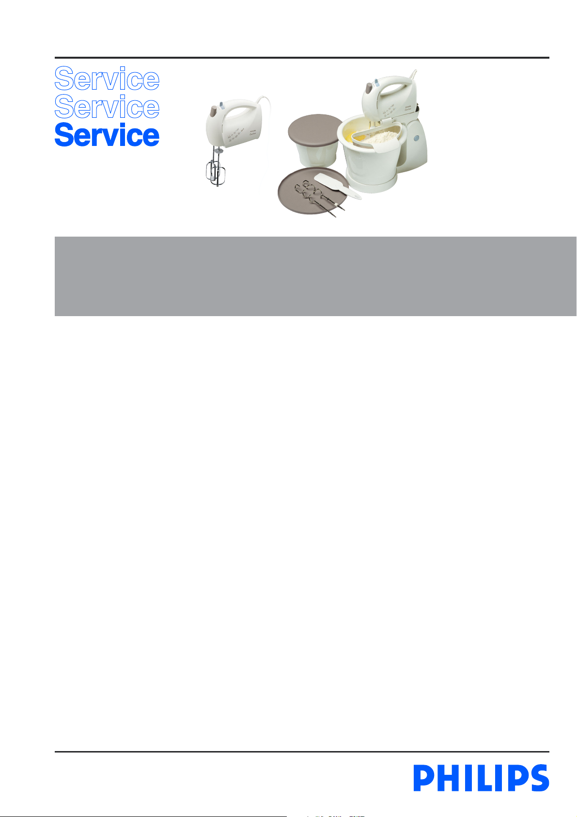
DISASSEMBLY- AND RE-ASSEMBLY ADVISE
- Use the blade of a knife to remove the hinged arm from the
stand. Insert the blade between the arm and the lower part
of the stand in such a way that the hinge located at triangle
(1) can be pushed inwards and the arm (2) can be pulled
upwards and out of the lower part of the stand.
- Reassemble the arm by placing it horizontally back into the
lower part of the stand, making sure the V-shaped groove
of the hinge fits round the guide rib in the lower part of the
stand.
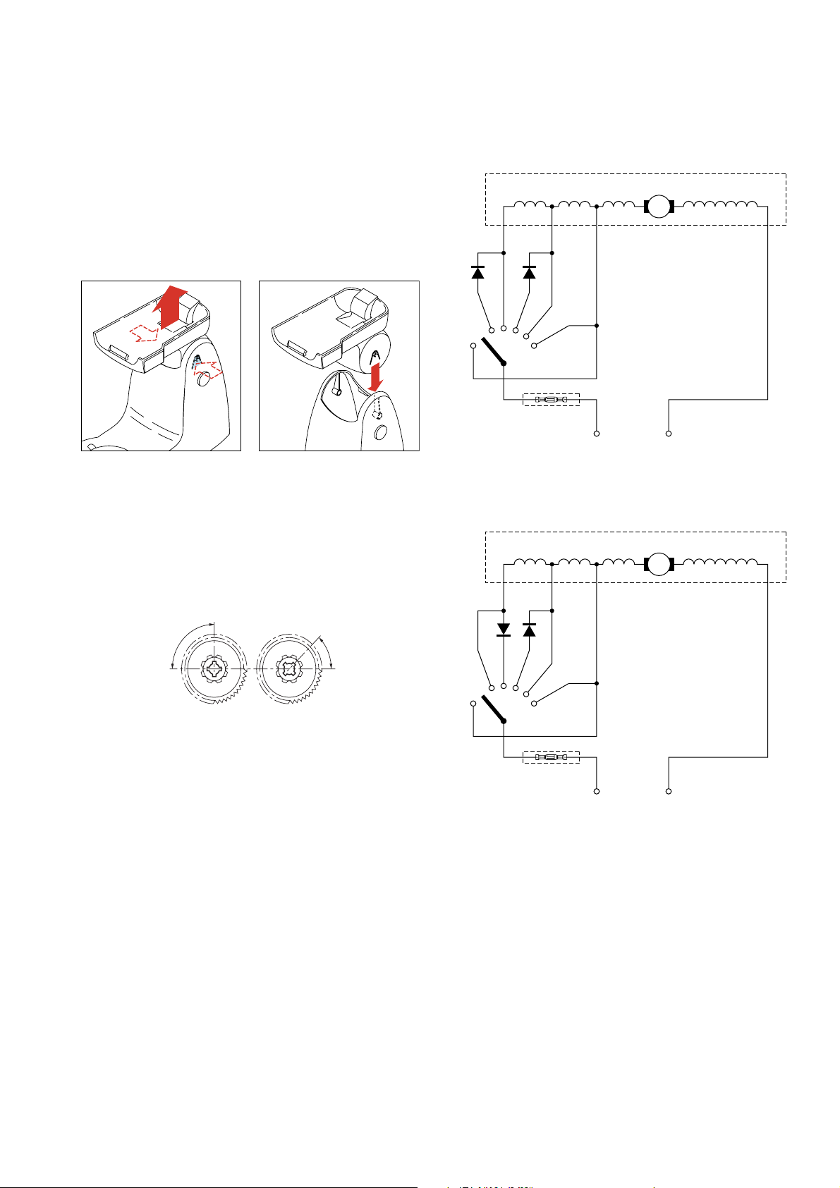
Circuit diagram 115 - 127 V
Motor assy
HR1566/AB
RI7115/AB
Rotor
Red GrayBlackGreen
2
1
1
REPAIR INSTRUCTION
Mounting gearwheels
When mounting the gearwheels make sure that the cams of
the gearwheels are situated at the front of the beaters.
The angle between the beaters must be 45°.
So when carrying out a repair be sure that the gearwheels are
mounted correctly (see Fig. 1).
90
˚
Fig. 1
45
˚
0
T
0
T
2
1
3
4
5
Circuit diagram 220 - 240 V
Motor assy
2
1
3
4
5
MAINS
Rotor
Red GrayBlackYellow
Lubrication
Use graphite grease code no. 4822 390 20004 to grease the
appliance on the following points:
1. Spaces between the teeth of the wormwheels.
2. Both sides of the wormwheel shaft.
Motor
The motor cannot operate properly, when, due to
contamination, carbon brush is unable to move freely in
guide bush and consequently cannot be pressed against the
commutator.
OPTIONAL (accessories)
- No specific issues.
MAINS
2-4
Page 3

PARTS LIST & EXPLODED VIEW
HR1566/AB
RI7115/AB
12
A
A
3
4
2 6
1
5
7
8
Pos Description Service code
1
Housing set - HR1566/AB
Housing set - RI7115/AB
2
Switch assy ( 220 V )
Switch assy ( 110 V )
3
Ejector
4
Ejector spring
5
Cord set – Mexico
Cord set – EU
Cord set – ARG
Cord set – Brazil
6
Cord clip
7
Cord grommet
8
Bearing plate
9
Strip beaters in pair
10
Dough hooks in pair
11
Motor buffer
12
Driven gearwheel
A
Screw 2,9 x 13
4206 136 54240
4206 136 54270
4206 136 55200
4206 136 53770
4206 133 94630
4206 132 07960
4206 100 02240
4206 100 02230
4206 100 02220
4206 100 02210
4206 133 86150
4206 133 53720
4206 133 94650
4206 136 54210
4206 136 54180
4206 133 53120
4206 133 82320
11
109
3-4
Page 4

PARTS LIST & EXPLODED VIEW
18
HR1566/AB
RI7115/AB
20
17
16
19
21
13
Pos Description Service code
13
Arm with sieve assy
14
Stand assy
15
Rubber stud
16
Sieve
17
Bowl 3,5 L
18
Big lid
19
Bowl 1,8 L
20
Small lid
21
Spatula
4206 136 55280
4206 136 54630
4206 133 53300
4206 136 53880
4206 133 94740
4206 133 94800
4206 133 94750
4206 133 94810
4206 133 89830
14
15
4-4
 Loading...