

Page 1
Cellesse Sense Active
HP 5232
PRODUCT INFORMATION
Type appliance : 13 V adapter from mains (AC)
Voltage (mains) : 220-240 V, 50/60 Hz and
110-127 V, 50/60 Hz
Motor : DC type
Max. powerconsumption : 8 Watts
Under pressure : 5 steps from 80 mbar to 250 mbar
Number of rollers : 2 driven and 2 non-driven (small)
Length cord : 2.5 m
Note: Product meets the requirements regarding
interference suppression on radio and TV.
Introduction
The Cellesse is a special massage system, designed to help to
reduce or prevent the unsightly appearance of cellulite.
Cellulite is the increased visibility of lumpy fat deposits through
the surface of the skin.
A common used description is ‘orange peel skin’ because of its
unique pitted, lumpy appearance.
Cellulite should not be confused with ‘cellulitis’, which is a
medical term linked to bacterial infection of the skin.
Cellulite can be reduced with the help of this product.
It can never be completely eliminated and will return when
neglected.
Cellesse can smooth the cellulite layer inside the skin by up to
49 % in one month, if the appliance is used 3 times a week for 15
minutes on each leg.
The Cellesse Sense Active does not reduce the fat in the
fat layer.
Published by Philips Domestic Appliances and Personal Care Printed in the Netherlands
4322 277 00243
00/03
PCS 101 479
©
Copyright reserved Subject to modification
Page 2
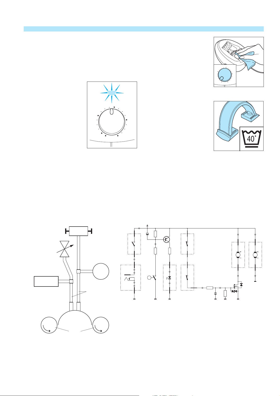
FUNCTIONAL DESCRIPTION OF THE HP 5232 CELLESSE
Function of the Cellesse
The product is connected to the mains and the ON/OFF switch
(A) is set to level 1 – 5.
The electronic suppression switch (C) switches on the motor of
the massage rolls (E). The Pump B starts to function.
The pump (B) only starts to function if the appliance is in a
proper contact with the skin so a vacuum of at least 80 mbar can
be reached.
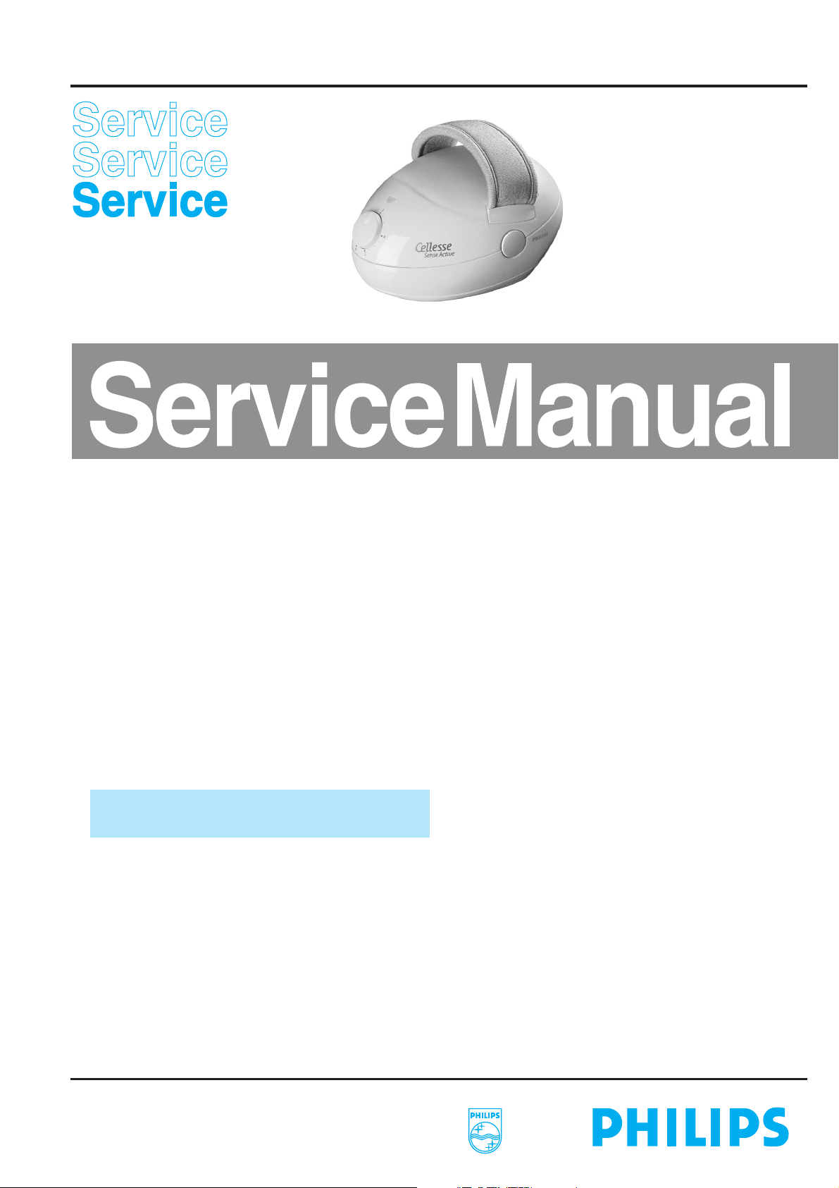
Once a vacuum of 80 mbar is
reached the small indicator lamp
on the front of the appliance lights
up to show that a proper contact
is made.
3
To avoid painful sucking in of the
skin, the vacuum stop buttons (F)
can be operated so that the
2
4
vacuum is eliminated.
The Cellesse only functions
properly if the product is put
properly on the skin so that the
1
0
5
pump can build up a vacuum in the
sucking area. (G)
Cleaning and maintenance
Never immerse the appliance in water or rinse it.
For the best results, clean the appliance after every treatment
session with a moist cloth and, if necessary, a drop of washing–up
liquid. Make sure the filter does not get damp.
Do not use alcohol, acetone, benzine, abrasives, scourers etc., to
clean the appliance.
Cleaning the rollers
To clean the rollers select Level 1.
Wipe the rollers clean with a
damp cloth.
Cleaning the hand-strap (1)
The hand-strap with claps can be
washed in a washing machine at
max. 40 °C.
Washing may slightly change the
colour of the strap.
3
2
1
4
0
5
VACU-stop Button
On/off Switch +
A
Suppression Switch
Level 1-5
El. Suppression Switch
C
Switches on the motor D
automatically at 80 mBar
underpressure
F
Sucking
Area
G
Rolls
E
Pump
Sleeves
+13V
TP6
not on
W4
PCB
red
A3
red
W3
TP5
A1
P-JACK
W1_2
TP4
TP3
TP1
TP2
W1_1
SOCKET-PCB
B
R1C3
TP7
R2
LEDPCB
A3
P
Q1
W9_1
TP8
D3
TP9
W9_2
not on
W1_1
PCB
A4
R3
not on
PCB
W1_2
W3_1
A5
W3_2
TP10
R4
TP15
C4
TP11
not on
W5
PCB
red
M1
M
blue
W6
TP12
Q2
R5
not on
PCB
W7
red
M
blue
W8
DAP0777
TP13
M2
TP14
PCS 101 480
Page 3

EXPLODED VIEW
1
2
D
101
16
10
11
18
102
A
I
B
E
4
3
A
103
7
104
B
G
C
C
H
20
8
19
5
F
E
I
D
G
B
C
F
H
17
106
105
A
105
9
D
21
14
6
12
13
Dx l
Screws C and D (2x) = 3 x 9
Page 4

PARTS LIST DISASSEMBLY ADVICE
Pos. description included service code
1 flexible hand-strap 4203 035 73370
2 hand support 4203 035 74270
3 set housing parts item 4 (2x) 9965 000 04105
4 set vacuum buttons 9965 000 04106
5 vacuum stop unit 9965 000 04116
6 power unit 9965 000 04117
7 pump item 103,104 9965 000 04118
8 pcb item 19 + 20 9965 000 04128
9 set tubes item 105 (2x), 9965 000 04129
106 (1x)
10 vacuum control unit item 18 9965 000 04130
– on/off switch
11 adjusting knob 4203 035 73430
12 filter (5x) 4822 480 10279
13 sieve 4203 035 73440
14 support rollers (2x) 4822 528 11337
15 set damping rubbers 103 + 104 9965 000 04134
16 set screws: consisting of Screw A + B 4822 310 11379
17 pouch 4822 600 10867
18 rattle spring 4822 492 32876
19 power jack 4822 265 11618
20 Led – green 4822 130 83081
21 adapter EURO 220-240 V 4822 219 10056
adapter UK 220-240 V 4822 219 10057
adapter USA 110-127 V 4822 219 10058
adapter JPN 100 V 4822 219 10059
adapter Korea 220 V 4822 219 10167
adapter Australia 240 V 4822 219 10174
adapter Brazil 115-220 V 4822 219 10171
adapter China 220 V 4822 219 10338
adapter CND 110-127 V 4822 219 10069
adapter Mexico 110-127 V 4822 219 10455
22 timer (not shown in the exploded view) 4203 035 73470
To open the product
Remove Flexible
Hand-strap 1
1
Remove Screw cover A + B
A
1
B
Set Adjusting knob (11)
to pos. 5
Remove Adjusting knob (11)
2
Remove Screw A + B
Remove Screw C
C
Remove Screw cover D (2x)
Remove Screw D (2x)
D (2x)
Directions for use: languages: E, P, GR, TR 4203 035 73460
Directions for use: languages: UK, F, D, NL, I 4203 035 73450
N.B. Components with numbers from 100 and higher
cannot be ordered separately
N.B. Screw Cover A + B will be damaged, when it is
removed For this reason, both covers are supplied free
when you order items 3 – 10 and 15.
PCS 101 481
Page 5

ASSEMBLY TIPS + TEST CRITERIA AND CONTROLS + POSSIBLE COMPLAINTS
ASSEMBLY TIPS
Adjusting knob (11) ;
–
Before assembling the adjusting
knob (11), set the cam of the
adjusting unit 10 to the indicated
position.
Adjusting the hand-strap
–
1
1
3
2
1
0
4
5
2
2
Spring: Before replacing
–
N.B.
To avoid dust from getting into the pump, the suction
–
opening has been closed with a plastic cap. Remove the
plastic cap before assembling.
After the product has been repaired, it should
–
function properly and has to meet the safety
requirements as laid down and officially established
at this moment.
2mm
3
L
M
4
S
POSSIBLE COMPLAINTS
Status Failure Cause
1. Switch in “OFF” position Pump functions ON/OFF switch defective
2. Switch set to level 1 Pump doesn’t function Adapter defective
3. Switch set to level 1-5 and LED burns Filter is clogged
product not placed on the skin Electronic switch defective
TEST CRITERIA AND CONTROLS
Total product 13.0 V 380 mA ± 10 %
Adapter: Primary voltage 220-240 V
Secondary voltage 13.0 V 400 mA
Pump 13.0 V 180 mA ± 10%
Motor rollers 13.0 V 180 mA ± 10 %
ON/OFF switch defective
Internal wiring broken
Defective PCB
Motor pump defective
Defective PCB
Voltage Ampere
if < 12.5 V adapter is defective
4. Switch set to level 1-5 and Product doesn’t function Electronic switch defective
product properly placed Defective PCB
Sleeves got loose
Vacuum stop defective
Gearing motor defective
Pump clogged – filter missing
Internal wiring broken
To check, if the product functions properly.
- Remove sieve (13).
- Set the switch to level 1. ⇒ The rollers should rotate continuously and the LED doesn’t burn.
- Cover the suction opening with the thumb. ⇒ The LED lights up.
- Press the vacuum stop-buttons. ⇒ The LED goes out and the rollers stop rotating.
PCS 101 482
 Loading...