

Page 1
Real Time Digital Video Recorders
Philips
Communication,
Security & Imaging
Installation Instructions
EN
Page 2

2
IMPORTANT SAFEGUARDS
1. Read Instructions - All safety and operating instructions should be read
before the unit is operated.
2. Retain Instructions - The safety and operating instructions should be
retained for future reference.
3. Heed Warnings - All warnings on the unit and in the operating instructions
should be adhered to.
4. Follow Instructions - All operating and use instructions should be followed.
5. Cleaning - Unplug the unit from the outlet before cleaning. Do not use
liquid cleaners or aerosol cleaners. Use a damp cloth for cleaning.
6. Attachments - Do not use attachments not recommended by the product
manufacturer as they may cause hazards.
7. Water and Moisture - Do not use this unit near water - for example, in a
wet basement, near a swimming pool, in an unprotected outdoor
installation, or in any area which is classified as a wet location.
8. Accessories - Do not place this unit on an unstable stand, tripod, bracket,
or mount. The unit may fall, causing serious injury to a person and serious
damage to the unit. Use only with a stand, tripod, bracket, or mount
recommended by the manufacturer or sold with the product. Any
mounting of the unit should follow the manufacturer's instructions and
should use a mounting accessory recommended by the manufacturer.
An appliance and cart combination should be moved with care.
Quick stops, excessive force, and uneven surfaces may cause the
appliance and cart combination to overturn.
9. Ventilation - This unit should not be placed in a built-in installation or
rack, unless proper ventilation is provided, or the manufacturer’s
instructions have been adhered to. The equipment must not exceed its
maximum operating temperature requirements.
10. Mechanical Loading - Mounting of the equipment in a rack shall be such
that a hazardous condition is not achieved due to uneven mechanical loading.
11. Power Sources - This unit should be operated only from the type of power
source indicated on the marking label. If you are not sure of the type of
power supply you plan to use, consult your dealer or local power company.
For units intended to operate from battery power or other sources, refer to
the operating instructions.
12. Grounding or Polarization - This unit may be equipped with a polarized
alternating-current line plug (a plug having one blade wider than the
other). This plug will fit into the power outlet only one way. This is a
safety feature. If you are unable to insert the plug fully into the outlet, try
reversing the plug. If the plug should still fail to fit, contact your electrician
to replace your obsolete outlet. Do not defeat the safety purpose of the
polarized plug.
Alternately, this unit may be equipped with a 3-wire grounding-type plug, a
plug having a third (grounding) pin. This plug will only fit into a
grounding-type power outlet. This is a safety feature. If you are unable to
insert the plug into the outlet, contact your electrician to replace your
obsolete outlet. Do not defeat the safety purpose of the grounding-type
plug.
13. Power Cord Protection - Power supply cords should be routed so that they are
not likely to be walked on or pinched by items placed upon or against them,
paying particular attention to cords and plugs, convenience receptacles, and
the point where they exit from the appliance.
14. Power Lines - An outdoor system should not be located in the vicinity of
overhead power lines or other electric light or power circuits or where it can
fall into such power lines or circuits. When installing an outdoor system,
extreme care should be taken to keep from touching such power lines or
circuits as contact with them might be fatal. U.S.A. models only - refer to
the National Electrical Code Article 820 regarding installation of CATV
systems.
15. Overloading - Do not overload outlets and extension cords as this can
result in a risk of fire or electric shock.
16. Object and Liquid Entry - Never push objects of any kind into this unit
through openings, as they may touch dangerous voltage points or short out
parts that could result in a fire or electric shock. Never spill liquid of any
kind on the unit.
17. Servicing - Do not attempt to service this unit yourself as opening or
removing covers may expose you to dangerous voltage or other hazards.
Refer all servicing to qualified service personnel.
18. Damage Requiring Service - Unplug the unit from the outlet and
refer servicing to qualified service personnel under the following conditions:
a. When the power supply cord or plug is damaged.
b. If liquid has been spilled or objects have fallen into the unit.
c. If the unit has been exposed to water and/or inclement weather (rain,
snow, etc.).
d. If the unit does not operate normally by following the operating
instructions. Adjust only those controls that are covered by the
operating instructions, as an improper adjustment of other controls
may result in damage and will often require extensive work by a
qualified technician to restore the unit to its normal operation.
e. If the unit has been dropped or the cabinet has been damaged.
f. When the unit exhibits a distinct change in performance--this
indicates a need for service.
19. Replacement Parts - When replacement parts are required, be sure the
service technician has used replacement parts specified by the
manufacturer or have the same characteristics as the original part.
Unauthorized substitutions may result in fire, electric shock, or other
hazards.
20. Safety Check - Upon completion of any service or repairs to this unit, ask
the service technician to perform safety checks to determine that the unit is
in proper operating condition.
21. Coax Grounding - If an outside cable system is connected to the unit, be
sure the cable system is grounded. U.S.A. models only--Section 810 of the
National Electrical Code, ANSI/NFPA No.70, provides information with
respect to proper grounding of the mount and supporting structure,
grounding of the coax to a discharge unit, size of grounding conductors,
location of discharge unit, connection to grounding electrodes, and
requirements for the grounding electrode.
22. Lightning - For added protection of this unit during a lightning storm, or
when it is left unattended and unused for long periods of time, unplug it
from the wall outlet and disconnect the cable system. This will prevent
damage to the unit due to lightning and power line surges.
23. The safety related fire, shock, and injury aspects of the models have been
investigated by Underwriters Laboratories Inc. to UL 1950 and CSA 22.2
No. 950-95. Burglary and theft protection features have not been evaluated
by Underwriters Laboratories.
FCC & ICES INFORMATION
(U.S.A. AND CANADIAN MODELS ONLY)
This device complies with part 15 of the FCC Rules. Operation is subject to the
following two conditions:
(1) This device may not cause harmful interference, and
(2) This device must accept any interference received, including
interference that may cause undesired operation.
NOTE: This equipment has been tested and found to comply with the limits
for a Class A digital device, pursuant to Part 15 of the FCC Rules and
ICES-003 of Industry Canada. These limits are designed to provide reasonable
protection against harmful interference when the equipment is operated in a
commercial environment. This equipment generates, uses and radiates radio
frequency energy, and if not installed and used in accordance with the
instruction manual, may cause harmful interference to radio communications.
Operation of this equipment in a residential area is likely to cause harmful
interference, in which case the user will be required to correct the interference
at his expense.
Intentional or unintentional changes or modifications, not expressly approved
by the party responsible for compliance, shall not be made. Any such changes
or modifications could void the user’s authority to operate the equipment. If
necessary, the user should consult the dealer or an experienced radio/television
technician for corrective action.
The user may find the following booklet, prepared by the Federal
Communications Commission, helpful: How to Identify and Resolve Radio-TV
Interference Problems. This booklet is available from the U.S. Government
Printing Office, Washington, DC 20402, Stock No. 004-000-00345-4.
This is a Class A product. In a domestic environment, this
product may cause radio interference, in which case, the
user may be required to take adequate measures.
Page 3
3
SAFETY PRECAUTIONS
The lightning flash with an arrowhead symbol within
an equilateral triangle is intended to alert the user to
the presence of uninsulated "dangerous voltage" within
the product's enclosure that may be of sufficient
magnitude to constitute a risk of electric shock to
persons.
The exclamation point within an equilateral triangle is
intended to alert the user to presence of important
operating and maintenance (servicing) instructions in
the literature accompanying the appliance.
Attention: Installation should be performed by
qualified service personnel only in accordance with the
National Electrical Code or applicable local codes.
Power Disconnect. Units with or without ON-OFF
switches have power supplied to the unit whenever the
power cord is inserted into the power source; however,
the unit is operational only when the ON-OFF switch
is in the ON position. The power cord is the main
power disconnect for all units.
SECURITE
L’éclair fléché dans un triangle équilatéral avertit
l’utilisateur de la présence d’une “tension dangereuse” non
isolée à l’intérieur de l’appareil et d’une valeur suffisante
pour présenter un risque d’électrocution aux personnes.
Le point d’exclamation contenu dans un triangle
équilatéral avertit l’utilisateur de la présence de
consignes d’utilisation et de maintenance importantes
dans la documentation qui accompagne l’appareil.
Attention. L’installation ne doit être effectuée que par
un personnel technique qualifié conformément à la
réglementation du Code Électrique National ou à la
réglementation locale pertinente.
Disjonction de l’alimentation. Les appareils avec ou sans
commutateurs ON-OFF sont alimentés à chaque fois
que le cordon d’alimentation est branché à la source
d’alimentation; toutefois, les appareils disposant de
commutateurs ON-OFF ne fonctionnent que lorsque le
commutateur ON-OFF est dans la position ON. Le
cordon d’alimentation constitue le moyen de disjonction
de l’alimentation principale de tous les appareils.
CAUTION: TO REDUCE THE RISK OF
ELECTRICAL SHOCK, DO NOT OPEN
COVERS. NO USER SERVICEABLE PARTS
INSIDE. REFER SERVICING TO QUALIFIED
SERVICE PERSONNEL.
WARNING
TO PREVENT FIRE OR SHOCK HAZARD, DO
NOT EXPOSE UNITS NOT SPECIFICALLY
DESIGNED FOR OUTDOOR USE TO RAIN OR
MOISTURE.
DANGER : POUR ÉVITER TOUT RISQUE
D’ÉLECTROCUTION, VEUILLEZ NE PAS
OUVRIR LE BOÎTIER. IL N’Y A PAS DE
PIÈCES REMPLAÇABLES PAR L’UTILISATEUR
À L’INTÉRIEUR DU BOÎTIER. POUR TOUTE
MAINTENANCE, VEUILLEZ VOUS ADRESSER
À UN TECHNICIEN SPÉCIALISÉ.
ATTENTION
POUR ÉVITER TOUT RISQUE
D’ÉLECTROCUTION OU D’INCENDIE,
VEUILLEZ NE PAS EXPOSER À LA PLUIE OU
À L’HUMIDITÉ UN APPAREIL NON CONÇU
POUR UNE UTILISATION EXTÉRIEURE.
WARNING: Electrostaticsensitive device. Use proper
CMOS/MOSFET handling
precautions to avoid
electrostatic discharge.
NOTE: Grounded wrist straps
must be worn and proper ESD
safety precautions observed
when handling the electrostaticsensitive printed circuit boards.
CAUTION: Lithium Battery
Danger of explosion if battery is
incorrectly replaced. Replace only with
the same or equivalent type
recommended by the manufacturer.
Dispose of used batteries according to
the battery manufacturer’s instructions.
A T T E N T I O N
O B S E R V E P R E C A U T I O N S
F O R H A N D L I N G
E L E C T R O S T A T I C
S E N S I T I V E D E V I C E S
Page 4
SICHERHEITSHINWEISE
Das Blitzsymbol im gleichseitigen Dreieck soll den
Benutzer auf nicht isolierte „gefährliche Spannung“ im
Produkt hinweisen, die ausreichend stark sein kann, um
die Gefahr von elektrischen Schlägen für Menschen
darzustellen.
Das Ausrufungszeichen im gleichseitigen Dreieck soll
den Benutzer auf wichtige Bedienungs- und
Wartungsanweisungen in der Dokumentation
hinweisen, die dem Gerät beiliegt.
Achtung: Die Installation darf nur von qualifiziertem
Wartungspersonal gemäß dem National Electrical
Code oder den gültigen örtlichen Vorschriften
durchgeführt werden.
Abtrennen der Spannungsversorgung: Die
Spannungsversorgung zu Geräten mit und ohne
Ein/Aus-Schalter ist hergestellt, wenn das Netzkabel an
eine Netzsteckdose angeschlossen ist. Das Gerät ist
jedoch nur betriebsbereit, wenn der Ein/Aus-Schalter
eingeschaltet ist. Bei allen Geräten erfolgt das Abtrennen
der Spannungsversorgung über das Netzkabel.
SEGURIDAD
El símbolo de flecha en forma de rayo situado dentro de
un triángulo equilátero pretende alertar al usuario de la
presencia de "voltaje peligroso" sin aislamiento dentro
de la caja del producto, el cual podría resultar de una
magnitud suficiente como para presentar un riesgo de
descarga eléctrica para las personas.
El punto de exclamación dentro de un triángulo equilátero
pretende alertar al usuario de la existencia de instrucciones
de funcionamiento y mantenimiento (reparación) en la
documentación suministrada con el aparato.
Atención: La instalación debe realizarla personal
cualificado en cumplimiento estricto del código
eléctrico nacional (en el caso de los EE.UU.) o de los
códigos locales aplicables.
Para Desconectar la Alimentación: Unidades no
equipadas con interruptores ON/OFF, son alimentadas
cuando el cable de alimentación es conectado a la
corriente eléctrica. Las unidades equipadas con
interruptores son alimentadas de igual forma, pero
adicionalmente requieren que el interruptor esté
posicionado en ON. El cable de alimentación es el
medio principal de desconexión del equipo.
VORSICHT: DAS GEHÄUSE ZUR
VERMEIDUNG VON ELEKTRISCHEN
SCHLÄGEN NICHT ÖFFNEN. DAS GERÄT
ENTHÄLT KEINE VOM BENUTZER ZU
WARTENDEN TEILE. REPARATUREN NUR
VON FACHPERSONAL AUSFÜHREN LASSEN.
WARNUNG
ZUR VERMEIDUNG VON FEUER UND
ELEKTRISCHEN SCHLÄGEN DAS GERÄT
NICHT REGEN ODER FEUCHTIGKEIT
AUSSETZEN.
PRECAUCIÓN: PARA REDUCIR EL RIESGO
DE DESCARGA ELÉCTRICA, NO ABRA LAS
TAPAS. EN EL INTERIOR NO HAY NINGÚN
COMPONENTE REPARABLE POR EL USUARIO.
LAS REPARACIONES DEBE REALIZARLAS
PERSONAL CUALIFICADO.
AVISO
PARA IMPEDIR EL RIESGO DE INCENDIO O
DESCARGA, NO EXPONGA EL APARATO A
LLUVIA O HUMEDAD
4
VORSICHT
ELEKTRISCHE SPANNUNG.
NICHT ÖFFNEN!
PRECAUCIÓN
RIESGO DE DESCARGA ELÉCTRICA
¡NO ABRIR!
Page 5
5
VEILIGHEIDSMAATREGELEN
Het symbool 'Bliksemflits met pijlkop' in een
gelijkzijdige driehoek wijst de gebruiker op de
aanwezigheid in de kast van het apparaat van nietgeïsoleerde spanningen die voldoende sterk zijn om
het gevaar van elektrische schokken op te leveren.
Het uitroepteken in een gelijkzijdige driehoek maakt de
gebruiker attent op de aanwezigheid in de bij het
apparaat behorende documentatie van belangrijke
aanwijzingen voor bediening en onderhoud.
Let op: Het apparaat mag uitsluitend door bevoegde
technici geïnstalleerd worden en wel in overeenstemming
met de National Electrical Code of de daarvoor
plaatselijk geldende richtlijnen.
Afsluiten voeding. Apparaten met of zonder
ON-OFF-schakelaar krijgen voeding zodra het
netsnoer in de wandcontactdoos wordt gestoken; het
apparaat is echter alleen operationeel als de ON-OFFschakelaar op ON staat. Het netsnoer kan bij alle
apparaten worden gebruikt om deze uit te schakelen.
SICUREZZA
Il simbolo triangolare di un fulmine con la punta a
freccia intende mettere in allerta l’utente riguardo alla
presenza di tensioni pericolose non isolate all’interno
del guscio dell’unità, che potrebbero essere di intensità
sufficiente per costituire pericolo di elettrocuzione.
Il punto esclamativo racchiuso in un triangolo
equilatero intende avvisare l’utente in merito alla
presenza di importanti istruzioni operative e di
manutenzione nella documentazione di
accompagnamento all’unità.
Precauzione: affidare l’installazione al solo personale
qualificato e nel rispetto del Codice elettrico nazionale
(USA) o dei codici locali pertinenti.
Scollegamento dell’alimentazione. Gli apparecchi con o
senza commutatori ON-OFF ricevono corrente tutte le
volte che il cavo di alimentazione è inserito nella presa di
forza; tuttavia, gli apparecchi muniti di commutatore
ON-OFF funzionano solo se quest’ultimo è in posizione
ON. Il cavo di alimentazione serve a scollegare dalla
corrente tutti gli apparecchi.
VOORZICHTIG: MAAK HET APPARAAT NIET
OPEN OM DE KANS OP ELEKTRISCHE
SCHOKKEN TE VERMIJDEN. BEVAT GEEN
ONDERDELEN DIE DOOR DE GEBRUIKER
MOETEN WORDEN ONDERHOUDEN. LAAT
ONDERHOUD EN REPARATIES UITVOEREN
DOOR BEVOEGDE TECHNICI.
WAARSCHUWING
TER VOORKOMING VAN BRANDGEVAAR
EN ELEKTRISCHE SCHOKKEN MAG DIT
ARMATUUR NIET AAN REGEN EN VOCHT
WORDEN BLOOTGESTELD.
ATTENZIONE: PER RIDURRE IL PERICOLO DI
SCOSSA ELETTRICA, NON APRIRE LE
COPERTURE. L’INTERNO NON CONTIENE
COMPONENTI CHE L’UTENTE PUÒ
RIPARARE PERSONALMENTE. RIVOLGERSI AL
PERSONALE DI ASSISTENZA QUALIFICATO
PER QUALSIASI INTERVENTO DI
RIPARAZIONE.
AVVERTENZA
PER IMPEDIRE INCENDI O SCOSSA
ELETTRICA, NON ESPORRE L’UNITÀ ALLA
PIOGGIA O ALL’UMIDITÀ.
VOORZICHTIG
GEVAAR VOOR ELEKTRISCHE SCHOK.
NIET OPENEN!
ATTENZIONE
PERICOLO DI SCOSSA ELETTRICA.
NON APRIRE.
Page 6
6
MEDIDAS DE SEGURANÇA
O símbolo do raio com a cabeça de uma seta dentro
de um triângulo equilátero serve para alertar o utilizar
para a presença de "corrente eléctrica perigosa" não
isolada no interior da caixa do produto que pode ser
suficiente para dar origem a choques eléctricos.
O ponto de exclamação dentro de um triângulo equilátero
serve para alertar o utilizador para a presença de instruções
de funcionamento e manutenção importantes na
documentação fornecida com o aparelho.
Atenção: A instalação deve ser efectuada por pessoal de
assistência técnica qualificado, de acordo com o
National Electrical Code (Normas de Electricidade
Nacionais) ou a legislação local aplicável.
Desconexão da electricidade. Unidades com ou sem
interruptores ON-OFF são activadas sempre que o
cabo eléctrico for ligado a uma fonte de alimentação.
No entanto, a unidade fica operacional apenas quando
o interruptor ON-OFF se encontrar na posição ON.
Para desligar a electricidade em qualquer uma das
unidades deve ser utilizado o cabo eléctrico.
CUIDADO: PARA REDUZIR O RISCO DE
CHOQUE ELÉCTRICO, NÃO ABRA AS
TAMPAS. O INTERIOR NÃO CONTÉM PEÇAS
QUE NECESSITEM DE MANUTENÇÃO.
A MANUTENÇÃO DEVE SER EFECTUADA
POR PESSOAL DE ASSISTÊNCIA TÉCNICA
QUALIFICADO.
AVISO
PARA EVITAR INCÊNDIOS OU CHOQUES
ELÉCTRICOS, NÃO EXPONHA À CHUVA OU
HUMIDADE UNIDADES NÃO
ESPECIFICAMENTE CRIADAS PARA
UTILIZAÇÃO NO EXTERIOR.
ZASADY BEZPIECZEŃSTWA
Błyskawica ze strzałką wewnątrz trójkąta
równobocznego ma za zadanie zwrócić uwagę
użytkownika na obecność nieizolowanego
"niebezpiecznego napięcia" wewnątrz obudowy
urządzenia, o wielkości stwarzającej niebezpieczeństwo
porażenia prądem.
Wykrzyknik wewnątrz trójkąta równobocznego ma za
zadanie zwrócić uwagę użytkownika na ważne
czynności, związane z obsługą i konserwacją
urządzenia, zamieszczone w Instrukcji obsługi.
Uwaga: Instalację urządzenia powinien wykonać tylko
wykwalifikowany personel, zgodnie z przepisami NEC
lub odpowiednimi przepisami miejscowymi.
Odłączanie zasilania. Urządzenia zarówno nie
posiadające, jak i posiadające wyłączniki ON-OFF
znajdują się pod napięciem, jeżeli tylko przewód
zasilający jest połączony ze źródłem zasilania. Jednakże
urządzenie działa tylko wtedy, gdy wyłącznik znajduje
się w położeniu ON. Przewód zasilający jest głównym
odłącznikiem zasilania dla wszystkich rodzajów
urządzeń.
UWAGA: ZE WZGLĘDU NA
NIEBEZPIECZEŃSTWO PORAŻENIA PRĄDEM
NIE WOLNO OTWIERAĆ POKRYWY. W
ŚRODKU NIE MA ŻADNYCH ELEMENTÓW,
KTÓRE MOGĄ BYĆ NAPRAWIANE PRZEZ
UŻYTKOWNIKA. NAPRAWĘ NALEŻY
POWIERZYĆ AUTORYZOWANEMU
PUNKTOWI SERWISOWEMU.
OSTRZEŻENIE
ABY UNIKNĄĆ POŻARU LUB PORAŻENIA
PRĄDEM NIE WOLNO WYSTAWIAĆ NA
DZIAŁANIE DESZCZU LUB WILGOCI
URZĄDZEŃ, KTÓRE NIE ZOSTAŁY
SPECJALNIE ZAPROJEKTOWANE DO
UŻYWANIA NA OTWARTYM POWIETRZU.
CUIDADO
RISCO DE CHOQUE ELÉCTRICO.
NÃO ABRIR!
UWAGA
NIEBEZPIECZEŃSTWO PORAŻENIA PRĄDEM
ELEKTRYCZNYM. NIE OTWIERAĆ!
Page 7

7
1PRODUCT DESCRIPTION ..........................................................................................................................9
1.1 Models ..............................................................................................................................................................9
1.2 Features..............................................................................................................................................................9
2 UNPACKING ..................................................................................................................................................9
2.1 Package Contents ..............................................................................................................................................9
3 FUNCTIONAL OVERVIEW ........................................................................................................................10
3.1 Front Panel of the Hi-Q ..................................................................................................................................10
3.2 Rear Panel of the Hi-Q....................................................................................................................................11
4TYPICAL SYSTEM CONFIGURATION ......................................................................................................12
4.1 Hi-Q Audio Connection..................................................................................................................................12
5QUICK START GUIDE (INITIAL POWER-UP) ........................................................................................13
6PASSWORDS AND MENU NAVIGATION..................................................................................................14
6.1 Passwords ........................................................................................................................................................14
6.2 Navigating the Menu ......................................................................................................................................14
7PROGRAMMING THE Hi-Q VIA THE MENU ..........................................................................................15
7.1 Menu Structure................................................................................................................................................15
7.2 Profiles ............................................................................................................................................................15
7.2.1 Creating a Profile ..................................................................................................................................................15
7.2.2 Configuring Recording Quality and Alarms ............................................................................................................15
7.3 Configuring the Calendar ................................................................................................................................16
7.3.1 Enabling and Viewing the Calendar; Submenu <Calendar><<Settings>>................................................................17
7.3.2 Inserting Profiles into the Calendar; Submenu <Calendar><<Edit Calendar>>........................................................17
7.4 Configuring Alarms ........................................................................................................................................18
7.4.1 Submenu <Alarms><<Inputs>> ............................................................................................................................19
7.4.2 Submenu <Alarms><<Outputs>> ........................................................................................................................19
7.5 Motion Detection............................................................................................................................................19
7.5.1 Submenu <Motion Detection><<Settings>> ..........................................................................................................20
7.5.2 Submenu <Motion Detection><<Active Zones>> ....................................................................................................20
7.6 Data Storage ....................................................................................................................................................21
7.6.1 Submenu <Data Storage><<Hard Drive>>............................................................................................................21
7.6.2 Submenu <Data Storage><<Archive>> ..................................................................................................................21
7.7 System ............................................................................................................................................................21
7.7.1 Submenu <System><<Password>> ........................................................................................................................21
7.7.2 Submenu <System><<Network>> ..........................................................................................................................21
7.8 Display ............................................................................................................................................................22
7.8.1 Submenu <Display><<Monitors>> ........................................................................................................................22
7.8.2 Submenu <Display><<Regional>> ........................................................................................................................22
7.9 Utilities............................................................................................................................................................23
7.9.1 Submenu <Utilities><<Shut Down>>....................................................................................................................23
7.9.2 Submenu <Utilities><<Misc.>> (Reconfiguring the Unit; PAL/NTSC reset) ..........................................................23
7.10 Information ....................................................................................................................................................23
7.10.1 Submenu <Information><<Activity Log>> ............................................................................................................23
7.10.1.1 Contents of Activity Log..............................................................................................................................23
7.10.2 Submenu <Information><<Help>>........................................................................................................................23
8OPERATOR FUNCTIONS (FRONT PANEL)..............................................................................................24
8.1 Alarm List........................................................................................................................................................24
8.1.1 Alarm List (Pop-up) Menu Options ........................................................................................................................24
8.2 On-screen Display (OSD)................................................................................................................................24
8.2.1 Alarm Icons............................................................................................................................................................24
Page 8

8
9PLAYBACK AND LIVE VIEW ......................................................................................................................25
9.1 Full-screen........................................................................................................................................................25
9.2 Quad Screen ....................................................................................................................................................25
9.3 Playback Search ..............................................................................................................................................25
10 ARCHIVING ................................................................................................................................................27
10.1 Connecting the Archive Drive ........................................................................................................................27
10.2 Connecting to Disk Array Device ....................................................................................................................27
10.3 Archive Modes ................................................................................................................................................27
10.3.1 Submenu <Data Storage><<Archive>> ..................................................................................................................28
10.3.2 Disk Full Behavior (via <Data Storage><<Hard Drive>> menu)............................................................................28
10.3.3 Archive Mode Settings ............................................................................................................................................28
10.4 Manual Archive (Tape Archive ONLY)............................................................................................................28
10.5 Tape Catch-up Feature ....................................................................................................................................29
10.6 Tape Archiving FAQ & Hints..........................................................................................................................29
11 MAINTENANCE ..........................................................................................................................................30
11.1 Temperature Monitoring..................................................................................................................................30
12 REPLACEMENT PARTS ..............................................................................................................................30
13 Hi-Q MANAGEMENT UTILITY..................................................................................................................31
13.1 Overview ........................................................................................................................................................31
13.2 Operating System Requirements......................................................................................................................31
13.3 Installation ......................................................................................................................................................31
13.4 Hi-Q Management Utility Operations ............................................................................................................31
13.4.1 Hi-Q Version Information......................................................................................................................................32
13.4.2 Bosch Security Systems, Inc. Software Update Site ....................................................................................................32
13.4.3 Transferring Files ..................................................................................................................................................32
13.4.3.1 File Selection Controls ..............................................................................................................................................32
13.4.3.2 File Transfers............................................................................................................................................................32
14 TROUBLESHOOTING ................................................................................................................................33
APPENDIX A – TECHNICAL SPECIFICATIONS ............................................................................................34
APPENDIX B – Hi-Q DEFAULTS ......................................................................................................................35
APPENDIX C – APPROVED ARCHIVE DEVICES ..........................................................................................36
APPENDIX D – Hi-Q ON-SCREEN CHARACTER SET ..................................................................................36
APPENDIX E – RACK EAR INSTALLATION ..................................................................................................36
For additional information, please visit our web site at
www.boschsecuritysystems.com.
Page 9
9
1PRODUCT DESCRIPTION
The Philips Hi-Q provides the highest quality digital video recording by utilizing MPEG-2 compression. Each input
has its own dedicated MPEG-2 compression engine, which allows each channel to simultaneously record high quality
full-motion video, without ever compromising recording quality or update rate. The recorder’s contact alarms, motion
detection, and 1-Touch Alarm feature, combined with its Calendar and Profile programming, provide ultimate
flexibility to get the most recording out of the unit, without ever sacrificing quality.
1.1 Models
Following are the two Philips Hi-Q models currently available:
•DVRRT4 (120 GB minimum hard drive)
• DVRRT4EP (240 GB minimum hard drive)
1.2 Features
• Simultaneous four-channel recording of high quality, real time digital video
• Audio recording (channel one)
• Time-lapse and real time recording modes
• Jog shuttle control
• Two monitor outputs (menu capability on MON A)
• Quad (MON A), full-screen, and sequential switching
• On-screen alarm indicators
• Simultaneous recording, playback, and archival
• Alarm and time/date search filters
• Motion detection with direction parameters
• 1-Touch, contact, motion, sync loss, and dark alarms
• Archive Player Software for Clip Retrieval, Archiving, & Authentication
• Management Utility software
• Compatible with Philips DVAD and DVAS Series Disk Arrays
• 19-inch rack mountable
2 UNPACKING
Unpack carefully to prevent damage to the equipment.
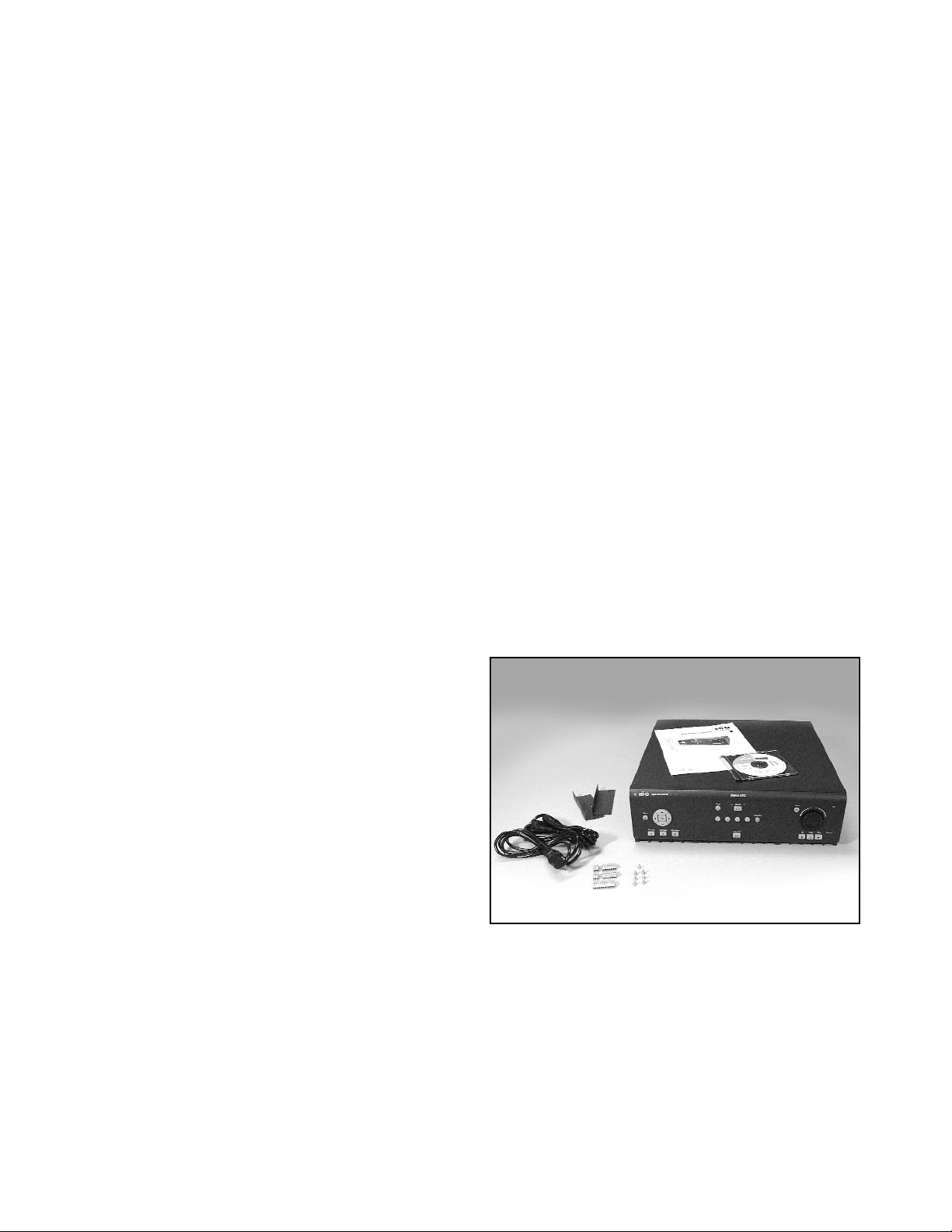
2.1 Package Contents
Check for the following items:
✔ Philips DVRRT4 or DVRRT4EP unit
✔ Mounting Ears (for a 19-inch rack) -
Part #303 3638 001 (Use Rack Mount Kit:
303 3740 501; see Appendix E for instructions).
✔ Screw Terminal Connectors:
• Two (2) 3-pin connectors - Part #303 1759 003
• Two (2) 8-pin connectors - Part #303 1759 008
• One (1) 12-pin connector - Part #303 1759 012
✔ Power Cords: 240 V - Part #303 0167 002;
120 V - Part #303 2143 001
✔ Keyboard Termination Plug (not pictured) -
Part #303 2728 001
✔ In-line Surge Protector (not pictured) - Part #303 3900 001
✔ Hi-Q Installation Instruction Manual (this manual) - Part #3935 890 403##,(where ## refers to a language
code, followed by the document’s revision number).
✔ CD-ROM containing Hi-Q Archive Player software, Hi-Q Management Utility software, and Installation
Instruction Manuals in English, French, German, Spanish, Dutch, and Italian - Part #303 3887 0103
If any items appear to have been damaged in shipment, replace the item(s) properly in the shipping carton and notify
the shipping company. If any items are missing, notify your Bosch Security Systems, Inc. Sales or Customer Service
Representative.
NOTE: The shipping carton is the safest container in which to transport the unit. Save it and all packing materials
for future use.
Page 10
3 FUNCTIONAL OVERVIEW
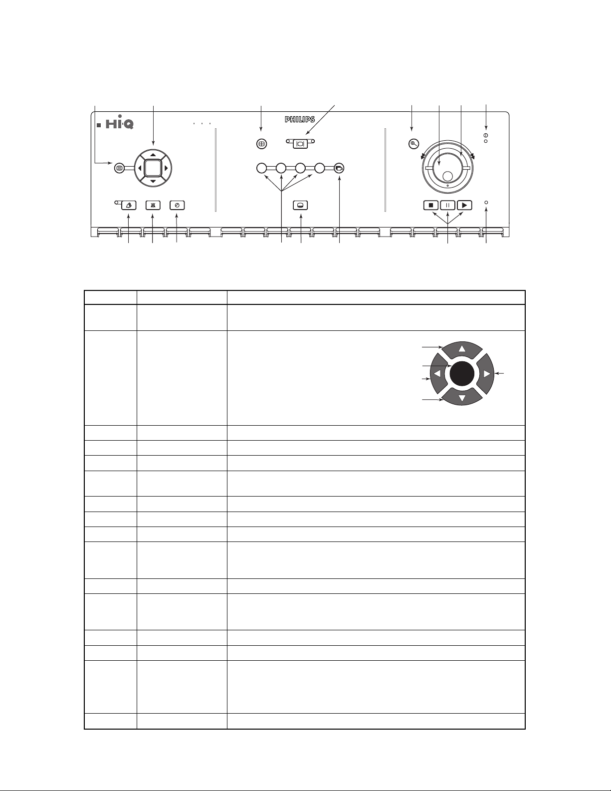
3.1 Front Panel of the Hi-Q
See Operator Functions (Section 8) for details regarding front panel controls.
Figure 3.1 Front Panel of the Hi-Q
10
Ref Name Description and Use
1Menu • Displays main menu on MON A
• Exits the menu from any level
2 Navigation OK button:
• Confirms selection
• Activates submenus
• Edits field values
Up, Down, Left, Right buttons:
• Navigates within menus
• Enters text and field values
• Digital PTZ control
3 Quad Switches MON A to quad view
4 Monitor Toggles control between MON A and MON B
5 Zoom Digitally zooms paused or recorded video 2X or 4X
6 Jog • Scrolls through menu text/ values
• Frame advance
7 Shuttle Forward and reverse playback speed adjustment (outside shuttle ring)
8 Power LED Indicates that the system has power
9 Alarm List Displays alarm list, newest first (LED is lit when there are noncleared alarms)
10 Alarm Clear • Acknowledges all active alarms, silences beeper, stops flashing alarm
icons on MON A, and ends sequencing of alarm video on MON B
• Resets active relays to nonalarm state
11 1-Touch Alarm Triggers alarm recording of all channels enabled for 1-Touch Alarm
12 Camera Display • 1, 2, 3, and 4 buttons display video from the selected camera
• Used for password entry
• 1, 2 used for Alarm List navigation (1 jumps to first page; 2 jumps to last page)
13 OSD Mode (On-screen Display) Toggles screen data on or off
14 Sequence Displays all cameras sequentially on selected monitor
15 Video Playback Stop: Stops playback video; press twice to return to live mode
Pause: Pauses live and recorded video
Play: Presents playback search screen (If playback video was paused,
normal speed is resumed)
16 Record LED Indicates the unit is recording
OK
Enter/Return
Up
Left
Down
Right
1
23
Digital Video Recorder
Quad
Monitor
A
4
B
5
Zoom
6
8
7
Menu
Alarm List
Alarm Clear 1-Touch Alarm
10
9
OK
11
12
OSD Mode
12
13
Sequence
43
Stop
Pause
Play Record
14
15
16
Page 11
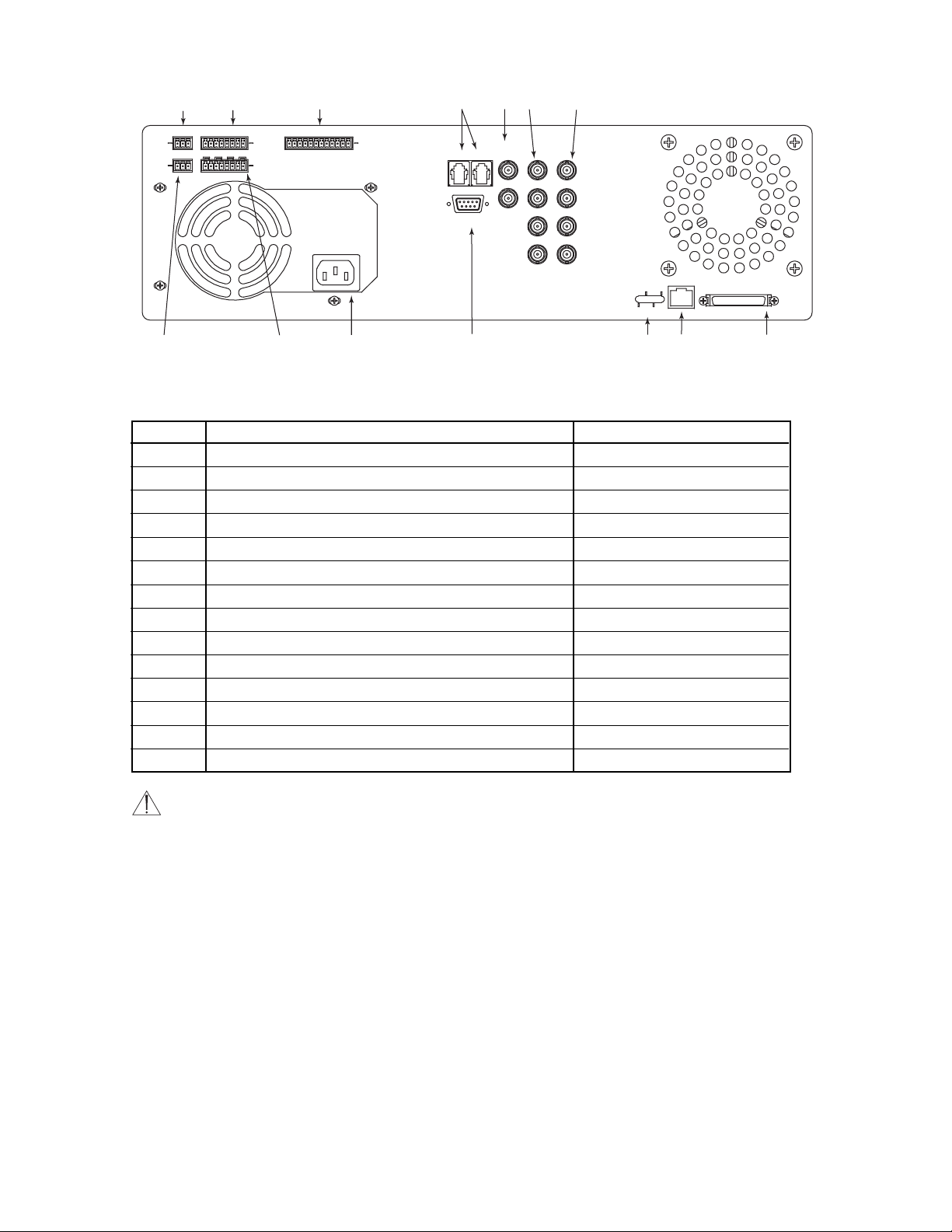
3.2 Rear Panel of the Hi-Q
Figure 3.2 Rear Panel of the Hi-Q
NOTES:
• Unused camera inputs should be disabled via the menu to avoid Vid Loss alarm.
• Each alarm input and output corresponds to the physical camera input/output channel (i.e., input #1 corresponds
to camera #1).
11
Ref Description Connector Type
1 AUDIO IN Screw terminal
24 ALARM INputs
**
Screw terminal
3 SDA biphase output for PTZ cameras
* **
Screw terminal
4 Keyboard loop-through and keyboard input
*
RJ-11
5 MON A and B outputs BNC
64 video inputs 75 Ω autoterminating BNC
74 video looping ports 75 Ω autoterminating BNC
8 AUDIO OUT Screw terminal
94 RELAY outputs (N/O or N/C)
**
Screw terminal
10 Auto-sensing power input (110/ 220 VAC, 50 / 60 Hz) IEC male
11 CONSOLE RS-232*/CCL port DB-9 male
12 Ethernet status lights
13 Ethernet 10/100BaseT RJ-45
14 SCSI connector for archiving device 50-pin high density D
* Functionality provided with software upgrade in later release.
** Belden 8760 twisted shielded cable (or equivalent) should be used for wiring to the alarm connector. Total length of
unshielded cable not to exceed 10 cm (3.9 in) on each connector port to maintain compliance with Directive 89/336/EEC.
AUDIO
IN
AUDIO
OUT
+ S –
+ S –
1
2
1 S 2 S 3 S 4 0
1 2 3 4
ALARM
IN
RELAY
3
+ S – + S – + S – + S –
4
5
6
SDA
LOOP
KEYBD
MONITOR
A
B
CAMERA
1
2
7
CONSOLE
8
9
10
11
3
4
ETHERNET
RX
COL
100
TX
13
12
SCSI
14
Page 12

4 TYPICAL SYSTEM CONFIGURATION
A typical system could contain the following components:
Figure 4.1 Typical Configuration
4.1 Hi-Q Audio Connection
The Hi-Q accepts both balanced and unbalanced audio inputs and outputs.
Examples for possible Audio Output connections:
12
Figure 4.2 Balanced Audio
Figure 4.3 Unbalanced Audio
PHILIPS
PHILIPS
Monitor A
+ S –
AUDIO
IN
+ S –
AUDIO
OUT
PHILIPS
1 S 2 S 3 S 4 0
1 2 3 4
ALARM
RELAY
IN
+ S – + S – + S – + S –
Monitor B
SDA
PHILIPS
MONITOR
CAMERA
A
KEYBD
LOOP
CONSOLE
1
2
B
3
4
ETHERNET
RX
COL
100
TX
Cameras
PHILIPS
PHILIPS
Archive Device (optional)
SCSI
+
+
–
S
S
Audio In
S
+
–S
+
Audio Out
–
S
+
–
To Balanced
S
Audio Device
+
2-conductor Shielded Cable
NOTE: Balanced connections are more immune
to noise (used for longer distances).
NOTE: Unbalanced connections are used to connect
audio to monitors using standard RCA-type connectors
(typically used for short distances).
–
Audio In
–
Audio Out
–
+
1-conductor Shielded Cable
To Unbalanced
–
+
Audio Device
Page 13

5 QUICK START GUIDE (INITIAL POWER-UP)
The default setting (Profile 1 only is in use) has all four channels recording high quality real time video. To change
these settings, proceed to Programming the Hi-Q via the Menu (Section 7). Refer to Appendix B for all default
settings.
1. Install the Hi-Q in a well ventilated location, ensuring that cooling vents are not blocked. Do not place the unit
on top of other equipment unless rack mounted.
2. Connect camera(s).
3. Connect audio (optional; See Figure 3.2 for configuration).
NOTES:
• By default, audio recording is disabled to prevent unintentional audio recording that could violate legal
restrictions. The administrator must enable the audio feature if desired.
• Audio recording occurs only if Channel 1 is recording video.
4. Attach a monitor to MON A for viewing Hi-Q configuration menus.
5. Locate the in-line surge protector packaged with the Hi-Q, and install it between the Hi-Q unit and the power
cord (see installation example below).
6. Apply power and select language, date, and time (see below). Time must be entered in 24-hour format.
7. The Hi-Q will now autodetect PAL or NTSC cameras.
NOTE: You must use the Shut Down procedure to power down the Hi-Q (Section 7.9.1) or data may be lost.
13
Page 14

6PASSWORDS AND MENU NAVIGATION
6.1 Passwords
If the Hi-Q is password enabled, the following screen appears when MENU (front panel) is pressed. See Section 7.7.1
for more information on passwords.
6.2 Navigating the Menu
IMPORTANT NOTES ON NAVIGATING MENUS:
These principles apply to all menus, thus are not repeated throughout this
manual.
• The Navigation buttons are used to move through the menus.
• The OK button selects the highlighted item.
• Placing an X in a checkbox indicates that the option is enabled.
Example: Renaming Profile 1 to Weekend.
Step Procedure Screen/Icon
1 Press MENU to display the Main Menu
Screen on MON A. Use the Arrow
Navigation buttons to highlight the desired
menu item (in this case, <Profiles>).
2 Press OK to open the text box of the
Profile being defined.
3 Use the Arrow Navigation buttons (or Jog)
to select the text characters, then press OK.
14
Figure 6.1 Navigation Buttons
(Front Panel)
OK
Weekend
Up
Enter/Return
Left
Down
OK
Right
Page 15

7PROGRAMMING THE Hi-Q VIA THE MENU
7.1 Menu Structure
7.2 Profiles
To program the Calendar, first set up the Profiles, then place them into the Calendar.
Profiles define the recording quality, update rate (time-lapse or real time settings), and alarm response for each camera.
Profiles are scheduled into the weekly Calendar and can automatically enable or disable video and audio recording.
7.2.1 Creating a Profile
The profile manager allows the user to name a profile (optional; 12 characters maximum), copy its contents, or reset it
to default. To edit a profile name, select menu option <Profiles> <<Manager>>.
7.2.2 Configuring Recording Quality and Alarms
1. Select the profile to be edited via <Profiles> <<Edit Profile>>:
15
<Menu Title> <<Submenu 1>> <<<Submenu 2>>>
Calendar Settings Edit Calendar
Profiles Manager Edit Profile
Alarms Inputs Outputs
Motion Detection Settings Active Zones
Data Storage Hard Drive Archive
System Password Network
Display Monitors Regional
Utilities Shut Down Misc.
Information Activity Log Help
Page 16

2. Configure details of the profile by checking the appropriate check boxes as shown below:
16
FIELD V
ALUES DEFAULT VALUE EXPLAINED
Profile Name Profile name as selected [profile number] Name of the selected profile.
in the <Edit Profile> screen
Active Alarms
1-Touch Alarm Each channel: Enabled If enabled (box is checked),
(front panel) Enabled or Disabled the corresponding alarm triggers
high quality real time recording.
Video Motion Each channel: Disabled Duration of alarm recording is
(via motion detectors) Enabled or Disabled determined by alarm settings
(see Section 7.4).
Video Dark Each channel:
(capped lens alarm) Enabled or Disabled
Auxiliary Each channel:
(contact closure via Enabled or Disabled
alarm inputs)
Relay Output Each channel: Disabled If enabled, an alarm on the channel
Enabled or Disabled triggers a relay output response.
Record Video Each channel: Continuous Defines type of recording for
• Continuous each channel.
• Event Only Event Only records pre-alarm
• Do Not Record video for the pre-alarm time
(see Section 7.4.1).
Record Audio Camera 1 only: Disabled Audio available on Channel 1
Enabled or Disabled if Video is enabled.
Image Quality Each camera: High Setting image quality lower extends
• High the record time.
• Medium
• Standard Plus
• Standard
Time Lapse Quality Each camera: Real Time Lower time-lapse setting extends
• Real Time (full motion) the record time.
• (NTSC)
2, 5, 10, 15, 30, 60 images/sec
• (PAL)
2, 5, 9, 12, 25, 50 images/sec
Estimated Calculated Calculated Time is estimated and is based
Recording Time on the current profile running
continuously without alarms.
X X X X
Page 17

7.3 Configuring the Calendar
Calendar configuration is used to schedule recording profiles into the weekly calendar. If the calendar is not being
used, only Profile 1 is needed. To change recording characteristics based on a day or time, first configure the profile,
then insert it into the 7-day calendar profiles.
7.3.1 Enabling and Viewing the Calendar; Submenu <Calendar><<Settings>>
7.3.2 Inserting Profiles into the Calendar; Submenu <Calendar><<Edit Calendar>>
17
Field Values Default Value Explanation
Calendar • Enabled Disabled If disabled, all active channels
• Disabled use Profile 1 all of the time.
Override The text screen below appears for selection of values.
Text Box Values Default Value
Profile [Profiles 1 to 6] [Profile 1]
Length of time [1-hour increments, 1
from 1–72]
Page 18

NOTE: If Stop Time is earlier than Start Time, the profile wraps to the next day. For 24-hour recording, Start and
Stop Time should be programmed to 00:00.
• Start Time: 24-hour time format, in 15-minute intervals
• Stop Time: 24-hour time format, in 15-minute intervals
• Days: Days to be scheduled for this profile
• Profile: Profile to be scheduled
• Select Enter
• Scroll down to view the 7-day calendar containing all programmed profiles:
7.4 Configuring Alarms
Alarm configuration estalishes alarm polarity, beeper, dwell time, and global pre-alarm and post-alarm settings.
18
Page 19

7.4.1 Submenu <Alarms><<Inputs>>
NOTE: Use 1-Touch Alarm (front panel) to trigger alarm recording for the duration of the programmed POST
ALARM time. Continue alarm recording by pressing 1-Touch Alarm again.
7.4.2 Submenu <Alarms><<Outputs>>
7.5 Motion Detection
Motion detection causes the system to alarm based on motion through a zone. Sensitivity, speed, and direction
settings can be set via these menus.
19
FIELD VALUES DEFAULT VALUE
Auxiliary Alarm Input Polarity - • Normally Open Normally Open
Cameras 1–4 individually • Normally Closed
Auxiliary Alarm Recording • Enabled Disabled
Follows Contact • Disabled
Pre-alarm Time [1 to 60 seconds] 30 seconds
Post-alarm Time:
Video Motion [1 to 60 minutes] 1 minute
Video Dark
Auxiliary
1-Touch
FIELD VALUES DEFAULT VALUE
Warning Beep • Enabled Enabled
• Disabled
Relay Output Polarity - • Normally Open Normally Open
Cameras 1–4 individually • Normally Closed
Relay Activation: [3 to 60 seconds, 5 seconds
Dwell Time - 1 second increments]
Cameras 1–4 individually
Follows Mode for Aux Alarm - • Enabled Disabled
• Disabled
Page 20

7.5.1 Submenu <Motion Detection><<Settings>>
7.5.2 Submenu <Motion Detection><<Active Zones>>
When Edit is selected, a frozen video image from the selected camera appears (by default, the entire area is an active
zone).
Use the DOWN arrow to move the cursor down into the image, then to the desired area. The light blue overlay
indicates the selected active region(s); multiple active zones are permitted. Press OK to toggle the cursor between
modes (see below). When complete, select Save. To deselect, press Clear All.
C
URSOR MODES: ACTIONS:
• Move - No change • Set All - Marks all zones active
• Activated - Selected • Clear All - Marks all zones inactive
• Clear - Deselected • Save - Exits screen and saves settings
• Cancel - Exits screen without saving settings
20
F
IELD VALUES D
EFAULT VALUE EXPLAINED
Suppression • Standard Standard • Standard: ignores small lighting
• Stable changes (less than 25%)
• None • Stable: ignores large lighting
changes (less than 50%)
• None: responds to all changes;
recommended for indoor applications
Target Size • 1 h x 1 v 2 h x 2 v Defines size of motion grid
(horizontally • 1 h x 2 v
by vertically) • 2 h x 1 v
• 2 h x 2 v
Target Direction • All (1) All (1) • All (1): detects motion in any
• All (2) direction
• Up • All (2): detects motion in any
• Down direction, but helps suppress false
• Left motion alarms
• Right • Up, Down, Left, or Right alarm only on specific motion
Target Speed 0 to 85 seconds 0– 40 seconds Alarms if object passes through camera’s
Min, Max field-of-view within range
Sensitivity [Between 100 (high) 70 Higher value is more sensitive to motion
and 1 (low)]
Page 21

7.6 Data Storage
7.6.1 Submenu <Data Storage><<Hard Drive>>
7.6.2 Submenu <Data Storage><<Archive>>
See Archiving, Section 10.
7.7 System
7.7.1 Submenu <System><<Password>>
Available Actions:
• Set Password. Press front panel buttons 1 through 4 to set the password (four to ten characters).
NOTE: This password is the same password used by the Hi-Q Management Utility.
7.7.2 Submenu <System><<Network>>
The Network menu allows access to settings that control the behavior of the recorder with respect to a network.
• Enter the IP, Subnet Mask, and Default Router addresses.
• Enter a Hi-Q recorder name to be used on the network.
* See Appendix D for Hi-Q on-screen character set.
** XXXX is the last 4 digits of the Hi-Q recorder serial number.
21
FIELD VALUES D
EFAULT VALUE
Disk Full Behavior • Overwrite Overwrite
• Stop Recording • Stop Recording is the
default (non-adjustable) if
a disk array is recognized
Disk 1 Status • Good Calculated
• Bad
Disk 2 Status • Good Calculated
• Bad
• Not Installed
Total Capacity Hard disk capacity, in GB Calculated
FIELD VALUES & DEFINITION DEFAULT VALUE
Password Protection • Enabled (requires password Disabled
for menu access)
• Disabled (no password
required for menu access)
FIELD VALUES DEFAULT VALUE
IP Address [0–255 in each block] 10.10.0.0
Subnet Mask [0 –255 in each block] 255.255.255.0
Default Router [0 –255 in each block] 10.10.0.1
Name [12 Characters]* Hi-Qxxxx**
Page 22

7.8 Display
7.8.1 Submenu <Display><<Monitors>>
NOTES:
• The Brightness setting affects the gain level on both recorded and live video.
• On quad-screen live video, the gain level for all camera inputs is forced to Automatic if any of the four channels is
set for Automatic. If all four channels are set to a Manual level, quad mode reflects the specified manual gain level
for each camera.
7.8.2 Submenu <Display><<Regional>>
22
FIELD VALUES DEFAULT VALUE
Camera Titles - [text entry, max Camera < 1, 2, 3, 4 >
Cameras 1–4 individually 12 characters]
Dwell Time: [1 to 60 seconds, 3
Monitor A 1 second increments]
Monitor B
Brightness (manual gain) Automatic: enabled or disabled AUTO
for MON A only - Values: –50 to 50
Cameras 1–4 individually
R
EGIONAL FIELD VALUES DEFAULT VALUE
Language • English English
• German
• French
• Italian
• Spanish
• Dutch
Time Mode • 24-hour 24-hour
• 12-hour
Current Date [date in the format DD-MMM-YYYY] [Current Date]
Current Time • 24-hour mode: HH:MM:SS [Current Eastern
• 12-hour mode: HH:MM:SS AM Standard Time:
HH:MM:SS (24-hour)
Page 23

7.9 Utilities
7.9.1 Submenu <Utilities><<Shut Down>>
NOTE: You must use the Shut Down procedure to power down the Hi-Q or data may be lost.
7.9.2 Submenu <Utilities><<Misc.>> (Reconfiguring the Unit; PAL / NTSC reset)
Select Defaults to reset the unit to its factory default settings (see Appendix B for Hi-Q defaults). The unit cycles
power, automatically detects camera type - PAL or NTSC, and configures itself accordingly.
7.10 Information
7.10.1 Submenu <Information><<Activity Log>>
To view a list of entries present in the Activity Log, specify the time frame in the screen as below.
Available Actions:
• View Log displays the Search Results submenu. Cancel stops the search.
7.10.1.1 Contents of Activity Log
• Error and warning messages
• Alarms
• Alarm clear and alarm review actions
• Setup changes
• Video Clip Archive Requests
• Power cycle messages
• Administrator log-in/log-out
• Archive tape change
7.10.2 Submenu <Information><<Help>>
Displays helpful descriptions. The current version of Hi-Q software is shown at the top of the Help screen. Press OK
to scroll to the next page.
23
ACTIVITY LOG FIELD VALUES DEFAULT VALUE
Options • Entries from Date/Time Entries from Date/Time
• Entries from Beginning
Date [All dates] [Current Date]
Time All times, 1 minute increments [Current Time] – 5 minutes
Page 24

8 OPERATOR FUNCTIONS (FRONT PANEL)
All operator functions are available from the front panel of the Hi-Q, without accessing the menu.
8.1 Alarm List
In live mode, press Alarm List to display all alarm events that have not been cleared (newest first), then select the
desired alarm and press OK. The pop-up box (below, right) appears for further selection.
Press 2 to jump to the last page of the alarms; press 1 to jump to the first page.
8.1.1 Alarm List (Pop-up) Menu Options
•Clear: Removes an item from the list on exit but does not delete it from hard drive.
• Play: Plays selected alarm video (internal hard drive only). To stop playback, press STOP.
Press STOP again to exit to live video.
• Archive: Displays the archive screen (see Section 10 for archiving details).
■
If the Hi-Q is programmed for Continuous archive, this option is disabled.
• Clear All: Permanently deletes all items in the alarm list at exit.
• Cancel: Removes the Pop-up menu from the screen, leaving the item highlighted.
• Exit to Live Mode: Exits the Alarm List and reverts to Live mode.
8.2 On-screen Display (OSD)
8.2.1 Alarm Icons
If OSD is on, icons appear at the top left-hand corner of the video.
ALARM TYPE ICON
Video Motion
Video (sync) Loss
Video Dark
Auxiliary (contact closure)
1-Touch Alarm
24
Page 25

9 PLAYBACK AND LIVE VIEW
9.1 Full-screen
Typical full-screen playback screen:
The text banner includes the playback speed, camera title, date, and time. If using digital PTZ (pan/tilt/zoom), a 2X
ZOOM or 4X ZOOM indicator also appears.
During live mode, the playback speed indicator is LIVE. To freeze the video, press Pause on the front panel. The text
banner now reflects LIVE||. When an alarm occurs, the appropriate alarm icon flashes between the two bitmaps
defined for each alarm type.
9.2 Quad Screen
Press Quad (front panel) for quad screen playback. In Quad view, audio playback and frame advance are disabled.
Live video in quad mode appears to be time-lapsing even though video may be recorded in real time.
9.3 Playback Search
To search for recorded video based on time/date, camera, or alarm type, press PLAY during live mode.
Search Procedure:
1. Press PLAY to present the Playback Search screen.
2. Enter search criteria.
3. Select Search Archive or Disk.
NOTE:
• When equipped with a disk array, the Hi-Q automatically searches the disk array if the From Date is set to an
older date than that of the video stored on the internal hard drive.
• When retrieving video from a tape archive device, 6 minutes of video is restored to the hard drive (1 minute
prior to the specified start time and 5 minutes after).
25
Page 26

4. Select Find Now.
Selecting the time/date plays back the video. If search criteria was entered, the Playback Search Results screen
appears as shown at right.
* TIP: Date From can be set to display the earliest video from the archive device. To do this, specify a date that is out of range
(like the year 1999), then press Find Now.
5. Select the desired video for playback. At the completion of
playback, the Playback Search Results screen is presented.
6. Select another video or exit search.
IMPORTANT NOTES:
• If searching a tape while in Continuous or Event Only
archive mode, you must first acknowledge the message to
take the tape device off-line. Video being recorded will be
identified for future archiving.
• If in Event Only archive mode, searching tapes may take
additional time due to the increased number of tape indices.
• When searching an archive tape, the tape indices are stored
on the unit’s hard drive for faster retrieval.
• If the search screen is exited or the tape is ejected, its indices
are purged from the system, so be sure that the current
search is complete before exiting.
• While in playback mode, press STOP to revert to the
previous Playback Search screen. Press STOP again to exit
and return to live mode.
Playback Search Results Options:
• Play: The selected alarm video is played.
• Archive: The archive box is displayed (see Section 10).
■
If Continuous Archive is set, Archive is disabled on this menu.
• New Search: Returns to the search screen. Current search parameters are stored as the default search criteria.
• Cancel: Removes the pop-up menu from the screen and leaves the item highlighted.
• Exit: Exits the playback function.
26
I
TEM VALUES DEFAULT VALUE
Devices to Disk, Archive Disk
Search
Date from Date Value Current Date*
Date to Date Value Current Date
Time from Time Value Current Time –
1 minute*
Time to Time Value Current Time
Cameras Cameras 1, 2, 3, and 4 All Cameras
Alarms Motion, Dark, Vid Loss, None Checked
Aux, 1-Touch
Find Now Search Results screen
is displayed
Exit Reverts to live video mode
Page 27

10 ARCHIVING
10.1 Connecting the Archive Drive
IMPORTANT NOTES:
• Do not set the tape device to High Compression mode.
• Approved Hi-Q archive devices are listed in Appendix C and at www.boschsecuritysystems.com.
• When retrieving video from an archive tape, 6 minutes of video is restored to the hard drive (1 minute prior to
the specified start time and 5 minutes after).
1. Prior to powering the tape device and the Hi-Q, connect the tape drive to the SCSI port of the Hi-Q using a
standard 50-pin high density, SCSI-2 connector.
2. Set the tape drive SCSI address to zero (0) (consult the device’s manual for setting the address).
3. If the tape drive’s SCSI port is not autoterminating, a suitable SCSI terminator must be used (consult the device’s
manual for the recommended terminator).
4. Apply power to the tape device and wait for initialization.
5. Apply power to the Hi-Q.
6. Ensure proper communication between the two devices via the Hi-Q menu <Data Storage><<Archive>>; the
screen should show the archive device type.
10.2 Connecting to Disk Array Device
1. With all power disconnected, connect the appropriate SCSI cable from the disk array to the Hi-Q.
2. Power the disk array and wait for it to initialize, approximately 1 minute (see Disk Array Instruction Manual).
3. Apply Power to the Hi-Q.
4. Ensure proper communication between the two devices via the Hi-Q menu <Data Storage><<Archive>>; the
screen should show the disk array archive device type.
NOTES:
• The above procedure must be followed before the Hi-Q’s auto SCSI device (Disk Array) detection can be
enabled.
• The disk array must be powered up and initialized to be recognized by the Hi-Q. If the Hi-Q is configured for
a disk array, it will wait up to 1 minute during its boot up process to give the disk array time to complete its
initialization. If the disk array is not detected within this time, the Hi-Q will complete its boot process and
display Archive Not Found.
10.3 Archive Modes
If using a tape archive device, Archive Now can be selected from the <Data Storage><<Archive>> menu. If the
selected archive mode is Event Only or Manual Only, archiving is available from the <Alarm List> or <Search
Results> screen.
27
Page 28

10.3.1 Submenu <Data Storage><<Archive>>
* not applicable with disk arrays
Available Actions:
• Eject temporarily suspends archiving, enabling the tape device’s Eject button. If the tape device is not busy writing
data, this menu selection is not required.
• Archive Now displays the Manual Archive screen (tape archiving only).
10.3.2 Disk Full Behavior (via <Data Storage><<Hard Drive>> menu)
• If Disk Full Behavior is set to Overwrite and the HDD is full, video continues to record, overwriting the oldest
video first. Note that Overwrite refers to the internal Hi-Q disk drives, and is not available if archiving via disk array.
• If Disk Full Behavior is set to Stop Recording and Archive Mode is set to Manual Only, recording stops when
the HDD is full.
10.3.3 Archive Mode Settings
NOTE: Event Only and Manual Archive modes are only applicable for tape devices.
• If Archive Mode is set to Continuous or Event Only, recording stops when it’s about to overwrite video
identified for archival.
•A message is displayed when the unit stops recording. Resume recording by selecting the menu option <Data
Storage><<Hard Drive>>RECORD.
• Event Only archiving is a global setting; an alarm on any camera causes archival of video from all cameras
recording at that time.
10.4 Manual Archive (Tape Archive ONLY)
Manual Archive archives video from the selected camera(s) for a specified date/time, to the archive device.
28
FIELD
VALUES DEFAULT VALUE
Archive Mode • Continuous Manual Only
• Event Only * • Continuous if a disk array
• Manual Only * is present
Drive Manufacturer Information displayed when archive device is installed.
Type & Model
Cartridge Label NOTE: Cartridge Label and Data Written appear only if in
Data Written Continuous or Event Only Archive Mode.
Page 29

Manual Archive Options:
10.5 Tape Catch-up Feature
The maximum time that an archive device can be off-line is based on all cameras continuously recording real time
video, at the highest quality. As long as the archive device is back on-line, receiving accumulated archive data before
the hard drive reaches capacity, no archive data is lost. This can be accomplished because the Hi-Q identifies or tags
video to be archived. When successfully archived, the tag is removed.
10.6 Tape Archiving FAQ & Hints
• Can I search and read tapes produced from another Hi-Q?
Yes.
• Can I perform a Manual archive when in Continuous or Event Only Archive Mode?
No. You must first change Archive Mode to Manual Only via the <Data Storage><<Hard Disk>>
<<<Archive>>> menu, then follow the instructions for manual archive.
• Why can’t I write to a tape?
Ensure the tape is not write-protected.
• Can a tape be relabeled?
Before a tape is overwritten, there’s a prompt to accept the existing tape label or create a new one.
• How much video can be retrieved from tape at a time?
When retrieving video from an archive tape, 6 minutes of video is restored to the hard drive (1 minute prior
to the specified start time and 5 minutes after).
• Why are there variances in the length of time it takes to search a tape?
Search time is dependent upon the type of archiving. Event Only archive tapes typically take longer.
• How can a tape be protected so that it is not mistakenly overwritten?
Depress the tape’s write protect tab.
• Why won’t the tape eject?
If the tape drive is busy or reading/writing data, the eject button is disabled. Either wait for the tape drive to
complete its task or use the Hi-Q’s menu option, Eject (see Section 10.2.1).
• What happens if a Manual Archive request consists of more data that the tape has remaining?
The tape fills with data, then prompts for a new tape. The remainder of the data is transferred to the
second tape.
• Does the Hi-Q continue to record and tag video for archival during a tape search?
Yes.
• Will data get lost if the tape drive has been off-line for a period of time?
The Tape Catch-up feature usually prevents archive data from being lost. If the tape device is off-line for an
extended period of time, data loss could occur.
• When can I append to a tape?
The type of archive data appending to the tape must be the same as when the tape was initialized
(formatted). For example, a formatted tape containing manual archive data can only be appended with
manal archive data.
29
F
IELD VALUES DEFAULT VALUE
Channels - • [each channel: Enabled] [All enabled]
1–4 individually • [each channel: Disabled]
Data from [all dates] Start date of clip
Time from [all dates] Start date of clip
Date to [all dates] End date of clip
Time to [all dates] End date of clip
Mode • Append Append
• Overwrite
Page 30

11 MAINTENANCE
In the event of a lost system password or for instructions for changing the Hi-Q’s battery, contact Bosch Security
Systems, Inc. Technical Support or your local Bosch Representative.
Field maintenance of this unit is limited to external cleaning and inspection. Refer all servicing to qualified personnel.
Contact your local Bosch Representative for Service.
Toll-free Voice Activated Phone Number: 800-326-3270 or 717-735-6300.
11.1 Temperature Monitoring
A temperature sensor monitors the Hi-Q’s internal temperature. In the event that the temperature exceeds the highest
recommended operating temperature, an on-screen error message appears on Monitors A and B.
12 REPLACEMENT PARTS
Part No. Description
303 3638 001 Mounting Ears (for a 19-inch rack. Use Rack Mount Kit #303 3740 501)
303 2143 001 Power Cord: 120 V
303 0167 002 Power Cord: 240 V
303 0588 001 Hi-Q Battery: (Rayovac
®
battery, lithium, 3 V/ 180 mAH, button cel type;
part # BR2325-B)
303 1759 003 3-pin Screw Terminal Connector
303 1759 008 8-pin Screw Terminal Connector
303 1759 012 12-pin Screw Terminal Connector
303 2728 001 Keyboard Termination Plug
3935 890 403## Hi-Q Installation Instructions; this manual (where ## refers to language & revision)
303 3887 0103 CD-ROM containing Hi-Q Archive Player software, Hi-Q Management Utility
software, and Installation Instruction Manuals in English, French, German, Spanish,
Dutch, and Italian
30
WARNING!
Do not open the top cover or
attempt to service the unit as this
may expose you to dangerous
voltages and other hazards.
Doing so will void the warranty!
Page 31

13 Hi-Q MANAGEMENT UTILITY
13.1 Overview
The Hi-Q Management Utility is a simple Windows®application that allows users to perform the following:
• View the contents of /Transfer a Software Update File (SUF) to the Hi-Q
• Transfer a Configuration File to the Hi-Q
• Retrieve a Configuration File from the Hi-Q
• Retrieve/View the contents of a System Activity Log from the Hi-Q
• View the Hi-Q version information
• Open a Web browser to the Bosch Security Systems, Inc. software update site
13.2 Operating System Requirements
The Hi-Q Management Utility runs under Windows 98/ME, Windows NT 4.0 (with Service Pack 6), and Windows
2000, and it must be configured with TCP/IP network protocol.
The Hi-Q Management Utility’s user interface is supported under the Danish, Dutch, English, Finnish, French,
German, Italian, Norwegian, Portuguese, Spanish, and Swedish localized versions of the operating systems listed
above but is displayed in English only.
13.3 Installation
Exit all Windows programs prior to installing the Hi-Q Management Utility executable .exe file. Run the application
and follow the instructions.
NOTE: The PC may need to be restarted after installation is complete.
13.4 Hi-Q Management Utility Operations
IMPORTANT: The Hi-Q IP address must be entered before proceeding. If the Hi-Q password
was never enabled or changed, enter 1,2,3,4 for the password.
31
Page 32

13.4.1 Hi-Q Version Information
Click to view the Hi-Q's Version Information
13.4.2 Bosch Security Systems, Inc. Software Update Site
Click to launch the PC's Web browser, then navigate to the Bosch Security Systems, Inc. software update site.
13.4.3 Transferring Files
• Software Update Files (*.suf) - upgrades to the Hi-Q software (improvements/extensions as released by Bosch
Security Systems, Inc.).
CAUTION:
Updating older Hi-Q recorders configured with external disk arrays to software version 1.30 will result in
LOSS OF ARCHIVED VIDEO. It is suggested to copy important archived video to VHS tape prior to
updating older Hi-Q’s to software version 1.30.
• Configuration Files (*.cfg) - used to save/restore the Hi-Q configuration (e.g. camera titles, alarm settings, etc.).
• System Activity Logs (*.log) - a list of Hi-Q activities and operations.
13.4.3.1 File Selection Controls
Select each file to be transferred between the Hi-Q and Hi-Q Management Utility by choosing the appropriate option.
A file is only transferred between the Hi-Q and Hi-Q Management Utility if its corresponding checkbox has been
set. Setting a checkbox enables (un-grays) the file's controls.
/ Files can only be transferred in one direction (i.e., PC to Hi-Q or Hi-Q to PC). Files to be
transferred from the PC to the Hi-Q must already exist on the PC. Files to be transferred from the Hi-Q to the PC are
created (or overwritten with permission of the user) at time of transfer.
Click to locate files.
Click the corresponding / viewer buttons to display the contents of SUF and SAL files.
13.4.3.2 File Transfers
After selecting file(s), click Transfer. Progress is displayed on a progress bar.
If you want to interrupt the transfer, click Abort.
32
Page 33

14 TROUBLESHOOTING
33
TROUBLE CHECKS ADJUSTMENTS
No video on one or more Verify proper 1 Volt p-p video Correct any coax, power or
cameras on MON A level input on affected channel(s) camera problems.
and make sure no ground loops exist.
Black screen on MON B output Same as above. Clear the alarm and check the
other channels.
No audio on playback Verify channel 1 video and audio Make programming
are enabled in the menus. Audio changes for video and audio.
can only be heard if full screen
playback is viewed on the monitor
for camera #1.
Temperature Alarm flashes Ensure the environmental temperature Move the unit to a
on-screen every 30 minutes is within the maximum and minimum temperature-controlled area
limits. within the maximum and
minimum limits.
Can’t access the menu Incorrect or lost password. Contact Bosch Security Systems
Technical Support for password
reset instructions.
Hi-Q Management Utility Wrong network connection. Program proper IP address
can’t access Hi-Q into the Hi-Q.
Cannot view Quad screen Ensure MON A LED is lit. Press Monitor, ensure the A
on MON A LED is lit, then press Quad.
Hi-Q Recorder Splash screen Verify input AC voltage is within If necessary to maintain a
periodically flashes on MON A the maximum and minimum limits constant AC input voltage,
and is constant. install UPS system.
Scheduled recording did not happen Calendar is disabled. Enable calendar via menu. If
already enabled, verify the
current profile settings.
Hi-Q does not detect disk array as Ensure the initial power up procedure Follow initial power up
archive device was followed (See Section 10.2) procedure. If followed, verify
SCSI cable is connected securely
Ensure proper communication between to the proper host port of the
the two devices via the Hi-Q disk array.
<Data Storage> <<Archive>>; the
screen should show the disk array
archive device type.
Page 34

APPENDIX A – TECHNICAL SPECIFICATIONS
34
SPECIFICATIONS
Electrical
Model Numbers Voltage Range Power (Operating)
DVRRT4, DVRRT4EP 110/220 VAC, 50/60 Hz 75 W
Digital Resolution:
On-line Storage Time: See table below.
Recording Speeds per Channel (IPS):
NTSC: 60, 30, 15, 10, 5, and 2 IPS.
PAL: 50, 25, 12, 9, 5, and 2 IPS.
Internal Hard Drive Capacity:
DVRRT4: 120 GB.
DVRRT4EP: 240 GB.
Video:
Inputs: Four (4), looping BNC connectors (auto-terminating), 0.5 to 2.0 Vp-p,
PAL/NTSC compatible.
Outputs (Mon A/B): BNC connectors, PAL/NTSC compatible, composite.
Compression: Four (4) independent MPEG-2 channels.
Audio:
Input (Mono): Screw terminal, balanced LL.
Balanced Audio Input:
4.0 Vp-p (max)/ 2.8 Vp-p (typ) differential level AUDIO IN (+) to
AUDIO IN (–).
Unbalanced Audio Input:
4.0 Vp-p (max)/ 2.8 Vp-p (typ) unbalanced level AUDIO IN (+) to
GROUND/SHIELD with AUDIO IN (–) tied to GROUND/SHIELD.
Output: Screw terminal, balanced LL.
Audio Output to Audio Input Gain: Unity Gain, typically.
Connectors:
Power: IEC male.
Console (Serial) Port:**RS-232, DB-9 male.
Video Inputs/Outputs: BNC.
Audio Inputs/Outputs: Screw terminal.
Ultra SCSI: DB-50, narrow, single-ended.
Network: RJ45, ethernet 10/100BaseT.
Alarm Handling:
Contact Alarms:
Alarm Inputs: Four (4) NO or NC inputs, contact closure to ground or
5V logic level.
Alarm Outputs: Four (4) NO or NC outputs; Rated at 40 VAC/DC, 1 A
Max (resistive).
Other Alarms: Sync, Dark, Manual, Motion.
Motion Detector (Each Input):
Parameters: Size, speed, direction; false alarm suppression.
Supported Archiving Device†:***
DVAD Series disk array
DVAS Series disk array
***Hi-Q Requires Firmware 1.10 or greater.
Network Software:
Hi-Q Archive Player:
Minimum PC Requirements
Operating System: Windows 98SE, ME, 2000, or XP with
Direct Show (Version 6.1 or newer)
Processor: 600Mhz Pentium III
RAM: 128MB
Free Disk Space: 2GB for storage of a 60-minute video clip
Video System: 800 x 600 with 16-bit color and 8MB of
video memory
Connection: 10/100 Base-T Network Interface
Hi-Q Management Utility:
Software upgrades, saving recording profiles and log files to PC.
The Hi-Q Management Utility runs under Windows 98/ME, Windows NT
(with Service Pack 6), and Windows 2000, must be configured with TCP/IP
network protocol.
Mechanical
Dimensions: 441.96 W x 464.8 D x 137.16 H mm
(17.4 W x 18.3 D x 5.4 H in).
Weight: 10.94 kg (24.1 lb).
Temperature: 10° to 45°C (50° to 113°F).
Relative Humidity: 0 to 90%, noncondensing.
Product Regulatory Compliance
Electromagnetic Compatibility (EMC):
Complies with FCC Part 15, ICES-003 and CE regulations.
Product Safety:
Complies with CE regulations, UL, CSA, EN and
IEC Standards.
Hi-Q Recorder
Recording Times (Hours)
60 IPS 30 IPS <30 IPS
(50 IPS PAL) (25 IPS PAL) (<25 IPS PAL)
NTSC:
High Quality 720 H x 480 V — 720 H x 240 V
Medium Quality 720 H x 480 V — 352 H x 240 V
Standard Plus Quality — 720 H x 240 V 352 H x 240 V
Standard Quality — 352 H x 240 V 352 H x 240 V
PAL:
High Quality 720 H x 576 V — 720 H x 288 V
Medium Quality 720 H x 576 V — 352 H x 288 V
Standard Plus Quality — 720 H x 288 V 352 H x 288 V
Standard Quality — 352 H x 288 V 352 H x 288 V
CAMERA
1
MONITOR
A
LOOP
KEYBD
B
2
3
4
AUDIO
IN
AUDIO
OUT
ALARM
IN
RELAY
SDA
CONSOLE
RX
TX
COL
100
ETHERNET
SCSI
+ S –
+ S –
1 S 2 S 3 S 4 0
1 2 3 4
+ S – + S – + S – + S –
** Biphase, keyboard, and console port reserved for future upgrades.
RECORD SPEED PER CHANNEL (IPS)
Real Time Modes Time-lapse Modes
NTSC 60 30 15 10 5 2
PAL 50 25 12 9 5 2
DVRRT4:
High Quality 15 – 22 31 39 89
Medium Quality 19 – 30 45 57 125
Standard Plus Quality *2741 8491164
Standard Quality *3863 8998244
DVRRT4EP:
High Quality 32 – 46 64 80 183
Medium Quality 39 – 61 92 116 255
Standard Plus Quality *5585 170 184 329
Standard Quality *78128 183 199 497
NOTE: This table reflects estimated recording times, assuming all video channels are
continuously recording at the given quality and record rate, without audio
recording.
*Interlaced video (50/60) is only available when recording at the High or Medium
Quality settings.
†Consult the Bosch Security Systems web site at www.boschsecuritysystems.com for an updated listing of supported devices.
Page 35

APPENDIX B – Hi-Q DEFAULTS
35
ITEM FACTORY DEFAULT VALUE
Alarm Setup
Auxiliary Alarms All Disabled
Auxiliary Alarm Input Polarity All Normally Open
Relay Output Polarity All Normally Open
Relay Output Enable Disabled
Relay Activation Dwell Time 5 seconds
Relay Activation FOLLOWS Mode for Disabled
Contact Closure Alarms
1-Touch Alarm Enabled
Dark Alarms All Disabled
Motion Detector Alarms All Disabled
Pre-alarm Recording Duration 30 Seconds
Post-alarm Recording Duration 1 Minute for All Alarm Types
Recording Setup
Video Recording All Continuous
Audio Recording Disabled
Estimated Recording Time Calculated
Image Quality Highest Quality
Time-lapse mode Real Time
Disk Full Behavior Overwrite; (Stop Recording with disk array)
Hard Drive: Data Redundancy For DVRRT4EP Model Only: Striping
Disk (1, 2) Status Determined by System
Total Disk Capacity Calculated
Archive Mode Manual; (set to Stop Recording with disk array)
Motion Detector Setup
Target Size 2 h x 2 v
Motion Zones All Grid Elements Active
Sensitivity 70
Suppression Standard
Motion Detector Direction All (1)
Target Speed 0– 40 seconds
Miscellaneous Setups
Profile Name Profile [Profile Number]
Warning Beeper Enabled
Front Panel Password Protection Disabled
Language Selection English
Date/Time On-screen Display Format 24-hour Mode; Not Affected by Restoring Factory Defaults
Activity Log Date/Time Current Date / Current Time – 5 Minutes
IP Address 10.10.0.0
Subnet Mask 255.255.255.0
Default Router 10.10.0.1
Name of Hi-Q Hi-Qxxxx
Camera Titles Camera n, where n is the camera number <1,2,3,4>
Brightness (Manual Gain) Adjustment on AUTO
Video Inputs (MON A Only)
Sequence Dwell Time - MON A & B 3 Seconds
Page 36

APPENDIX C – APPROVED ARCHIVE DEVICES*
Supported Archiving Devices:* DVAS Series disk array
DVAD Series disk array
Sony®AIT-2 Single Tape Drive.
* Consult the Bosch Security Systems, Inc. web site, www.boschsecuritysystems.com, for updated listing of supported devices.
APPENDIX D – Hi-Q ON-SCREEN CHARACTER SET
Character Set:
<space> ! " # $ % & ' ( ) * + , - . / 0 1 2 3 4 5 6 7 8 9 : ; < = > ? @ A B C D E F G H I J K L M N O P
Q R S T U V W X Y Z [ \ ] ^ _ ` a b c d e f g h I j k l m n o p q r s t u v w x y z { | } ~ ‚ ƒ ˆ ‹ ‘ ’ " "
• – — ˜ › ¢ £ ¥
I
I
§ ª « ° ±2µ¶ · º » 1⁄41⁄2 ¿ Ä Å Æ Ç É Ñ ∞Ü ß à â ä å æ ç è ê ë ì î ï ñ ò ô ö ÷ ø ù û ÿ
APPENDIX E – RACK EAR INSTALLATION
Installation:
Tools required: Medium sized Phillips head screwdriver.
Items included in supplied Rack Mount Kit (quantity):
(2) Rack mount ears
(6) Phillips pan head screws with integral lock washers
Mounting:
1. Remove the 6 flat head screws located near the front panel on the right and left side of the housing and discard.
2. Attach the mounting ears to each side using the 6 supplied Phillips pan head screws with lock washers
and tighten securely.
3. Install the unit into the rack using the Rack manufacturer’s supplied hardware.
________________________
Windows®is a registered trademark of Microsoft Corporation.
Rayovac®is a registered trademark of Rayovac Corporation.
3935 890 40315 03-27 © 2003 Bosch Security Systems, Inc.
Printed In U.S.A. All Rights Reserved. Philips®is a registered trademark of
Philips Electronics N.V.
Updated July 10, 2003. Data subject to change without notice. Refer to
www.boschsecuritysystems.com for latest information.
 Loading...