

Page 1
Philips Domestic Appliances and Personal Care
Azur Mastervapor
HI 994/A
X
A
IN
M
M
MAX
Service Manual 4822 729 21714 is herewith cancelled
PRODUCT INFORMATION
Feataures : inox sole plate
variable steam
shot of steam
jet of steam
detachable water tank
control lamp : water tank empty, provided the tank is properly placed
contents water tank 0.68 l
contents boiler 0.3 l
length steam hose 1.8 m
length cordset 2.1 m
max. steam output 70 gr./min.
Voltage : 220 - 240 V
Power consumption : boiler :1370 Watts
pump : 30 Watts
iron : 800 watts
Sole plate temperature : dial at max. position : 225 ± 25 ºC
MSH coding 8820 994 00000
Product meets the requirements regarding interference
suppression on radio and television.
PublishedbyPhilipsDomesticAppliancesandPersonalCare PrintedintheNetherlands
4822 729 22052
98/10
PCS 99 731
©
Copyrightreserved Subjecttomodification
Page 2
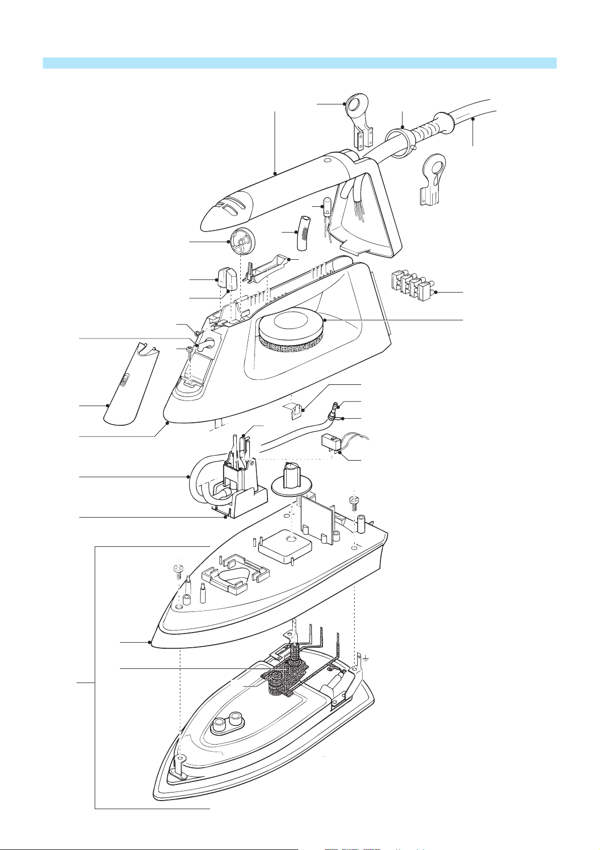
EXPLODED VIEW IRON
17
1816
19
15
25
13
14
12
11
A
20
21
9
B
22
7
26
23
24
6
10
5
C
4
C
3
2
1
D
Screws :dxlinmm
PCS 99 732
A 1x 3.0 x 12
B 3x 3.5 x 14
C 3x M4 x 12
D 1x M4 x 23
Page 3
PARTS LIST + DISASSEMBLY ADVICE IRON
pos description service code
1
2
3
4
5
6
7
9
10
11+12
13
14
15
16
17
18
19
20
21
22
23
24
soleplate unit 220 - 240 V
thermostat
skirt
deviator assy
steam hose
handle printed
nose cover
jet of steam hose
microswitch
set operation knobs
steam dial
steam command lever
pilot light
inlay printed
swivel ear
ball swivel
steam hose / cable
term. block ( 4 pole )
therm. dial
rattle dial
hose joint
spring clamp
4822 259 10194
4822 282 30238
4822 442 00414
4822 360 10138
4822 690 80134
4822 498 10587
4822 441 80981
4822 690 80133
4822 282 30239
4822 410 10555
4822 410 10556
4822 410 62968
4822 134 41161
4822 442 00413
4822 325 60391
4822 325 60389
4822 530 21058
4822 290 61189
4822 410 10557
4822 492 71445
4822 530 40513
4822 492 71001
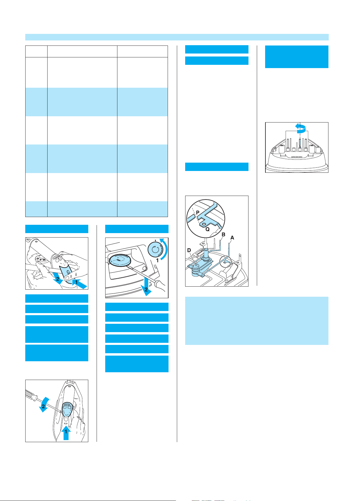
THERMOSTAT 2
SKIRT 3
remove DIAL 21
remove NOSE COVER 7
remove INLAY 16
remove STEAM DIAL 13
remove BUTTON 11
remove BUTTON 12
remove SCREWS THER-
MINAL BLOCK 20
remove STEAM HOSE 19
remove THERMINAL
BLOCK 20
remove CLAMP 24
remove SCREW B (3x)
remove SCREW C (3x)
remove HANDLE 6
THERMOSTAT 2 ONLY
cut CONDUCTOR A
at location P
remove SCREW D
ASSEMBLY
REQUIREMENTS
THERMOSTAT 2
Instead of metal conductor A,
the new thermostat has a wire
with AMP clamp.
After fixing screw D, connect
the AMP clamp to tag Q.
After assembling SKIRT 3
ALWAYS turn conductor B
through 180 degrees.
NOSE COVER 7
LAMP 15
MICROSWITCH 10
STEAM DIAL 13
JET OF STEAM
BUTTON 11
SHOT OF STEAM
BUTTON 12
remove NOSE COVER 7
remove SCREW A
DIAL 21
HANDLE 6
SOLEPLATE 1
MICROSWITCH 10
DEVIATOR 5
THERMINAL BLOCK20
JET OF STEAM
HOSE 11
remove DIAL 21
remove NOSE COVER 7
remove INLAY 16
remove STEAM DIAL 13
remove BUTTON 11
remove BUTTON 12
remove SCREWS THER-
MINAL BLOCK 20
remove STEAM HOSE 19
remove CLAMP 24
remove SCREW B (3x)
ADJUSTMENT AND CONTROLS
Thermostat 2
Thermostat(2)supplied as a spare part or fitted to the sole plate
( 1 ) has already been adjusted by the supplier and secured by glue.
To avoid disfunction of the iron , NEVER readjust the
thermostat.
PCS 99 733
Page 4

EXPLODED VIEW BOILER
30
51
48
33
E
34
35
G
110
109
105
47
46
44
45
54
41
F
101
42
38
39
37
111
107
36
106
49
108
52
40
PCS 99 734
50
Screws :dxlinmm
E 4x T10 x 16
F 2x 3.5 x 17
Page 5

PARTS LIST + DISASSEMBLY ADVICE BOILER
pos description service code
detach. tank + filler cap 31
30
tray
33
cover + rubber display
34
rubber display
35
boiler complete
36
black cold water hose
37
red steam hose
38
one way valve + buffers + sieve
39
pump + buffers + fuse
40
red hose
41
control / steering unit / pcb
42
cordset Euro
43
cordset Italy
cordset UK
holder detach. tank
44
connecting tube
45
reed contact
46
microswitch
47
switch
48
rubber buffer
49
bottom housing
50
pilot lamp
51
sliding door
52
rubber foot
53
4822 418 10221
4822 418 10222
4822 441 11847
4822 442 00678
4822 218 11551
4822 530 10315
4822 530 10316
4822 360 10245
4822 360 10246
4822 530 10317
4822 214 11983
4822 321 11031
4822 321 11029
4822 321 11028
4822 256 10322
4822 530 10318
4822 277 11662
4822 277 11662
4822 276 13822
4822 466 11398
4822 441 11848
4822 277 11662
4822 443 10502
4822 462 10837
54 Clamping ring 4822 532 12742
GENERAL
OPEN THE STAND
remove DETACH. TANK 30
remove TRAY 33
remove TORQUE
SCREW E (4x)
with screwdriver unlock the
HOOKS
remove COVER 34
COVER 34
DISPLAY RUBBER 35
STEAM HOSE /
CABLE 19
CORDSET 43
SWITCHES 48
DOOR 52
BLACK COLD WATER
TUBE 37
RED STEAM TUBE 38
RUBBER BUFFERS 49
BOILER COMPLETE 36
open the STAND
PUMP 40
CONNECTING
TUBE 45
open the STAND
lift CONNECTING
BLOCK 101
remove SCREW F (2x)
lift HOLDER DETACH.
TANK 44
remove TUBES 41 and 45
remove connect. wires PUMP
PCB 42
open the STAND
lift CONNECT.
BLOCK 101
remove purper wire PCB
remove SCREW F (2x)
lift HOLDER DETACH.
TANK 44
lift PUMP 40
remove connect. wires
ADJUSTMENT AND CONTROLS
– To avoid leakage of the sealings and damage to the
components in and on the boiler, NEVER clean the boiler
with vinegar, a descaling agent or other chemicals.
– The boiler doesn’t contain serviceable parts
Never disassemble the boiler body and /or components on
and in the boiler.
– ALWAYS REPLACE THE BOILER ( 36) WHEN:
*
the mechanical safety valve ( 105 ) has been activated.
*
the pressostat ( 106 ) doesn’t function properly.
*
the thermo fuse ( 107 ), boiler thermostat ( 108 ) or
hand - resettable safety thermostat ( 109 ) are open,
because the boiler has been subjected to too high
temperatures.
*
the sensor ( 110 ) doesn’t function properly
*
the electrovalve ( 111 ) fails or the sieve is soiled with
scale.
–
After the product has been repaired, it should function
properly and has to meet the safety requirements as laid
down and officially established at this moment.
ONE-WAY VALVE 39
open the STAND
lift CONNECT.
BLOCK 101
remove TUBES 37 and 41
REED CONTACT 46
MICROSWITCH 47
open the STAND
remove SCREW F
lift CONNECT.
BLOCK 101
lift PUMP 40
remove SCREW F (2x)
lift HOLDER DETACH.
TANK 44
N.B. Components pos. 46, 47 and 51 are supplied in one set
Components with numbers from 100 and higher cannot
be ordered separately
PCS 99 735
Page 6

FUNCTIONAL DESCRIPTION OF THE HI 994 MASTER VAPOR
Description of the water supply.
Apin(1)inthebottom of the housing activates the valve in
•
the watertank.
The microswitch(2)makes sure that the electric circuit is
•
closed, provided the tank has been fit properly.
The reed contact(3)makes sure that the system switches
•
off when there is no sufficient water in the tank.
The floater in the tank(4)drops when water is
pumped to the boiler.
Once the floater is at the bottom, the magnet in the
floater activates the reed contact, so the reed contact
is openend and the circuit is interupted.
The light goes on.
Sensor(5)intheboiler activates the pump, when the
•
water level reaches the lowest specified water level.
The sensor detects the resistance between the sensor
and the water level.
When the water level is low, the resistance will be
rather high and the pump is activated.
When the water level is high, the resistance is low and
the pump stops.
The HI994 consists of an iron and a stand.
Cold water is pumped from the detachable tank to the boiler,
where steam is generated.
After operating the steam valve, steam flows into the iron.
The stand consists of:
I ) A detachable tank :
There is a floater in the tank, which activates the reed
contact.
II ) A pump :
The pump is protected against overheating by an
automatically resettable cut-out.
III) A boiler :
On the boiler the following controls are fitted
-
hand-resettable safety thermostat
-
boiler thermostat
-
fuse
-
pressostat
-
mechanical safety valve
-
sensor
-
electro valve + sieve
IV) An electronic control / steering unt, which consists of :
a PCB, located below the pump
a sensor, located in the boiler
Functioning of the system
– The water tank is filled with water and fitted on the stand.
– Switch is operated, light goes on, indicating that water
is being heated.
– Water is pumped from the tank to the boiler. This can be
clearly heared.
– Once enough water is in the boiler, the pump stops.
– When the pressure is within the limites 2 ± 0.3 bar, there is
sufficient steam to start ironing and the the pressostat comes
into operation and switches off the element.
–
Switch can be operated to start ironing.
Pilot light switch goes on.
–
Once the water level reaches the lowest specified level, the
sensor activates the pump.
–
The whole process starts again.
The pump is a vibration pump which makes noise during pumping.
This is normal. The pump doesn’t pump water continuously.
It pumps at the start and during ironing after finishing steaming.
STAND
Safety
therm.
Boiler
therm.
N
S
Waterlevel
control unit
Steam-
valve
IRON
Steamswitch
PCS 99 736
p
Prestostat
Pump
Thermostat
Page 7

POSSIBLE FAILURE CAUSES
COMPLAINT : WATER RUNS OUT OF THE SOLEPLATE
Check if temperature dial ( 21 ) is set to the highest position.
•
If steam dial ( 13 ) is set to the highest pos. and the temp. dial to medium or low position the
soleplate doesn’t become hot enough and the steam condenses.
Steam from former use condensed in the hose.
•
This is normal.
The water disappears when the iron heats up.
COMPLAINT : IT DOESN’T STEAM
operate the steam command lever ( 14 )
•
no click is heared
<
the electrovalve ( 111 ) is broken.
→
replace the complete boiler ( 36 ).
*
the microswitch of the steam activator is broken.
→
replace the component.
*
a “click” is heared clearly
<
the water supply is OK
<
GENERAL TEST :
connect the system to the mains, switch the boiler and iron on, set the temp. dial to the
•
highest pos.
when measuring : 800 Watts
<
when measuring : 1400 Watts
<
when measuring : 2200 Watts
<
pump makes noise continuously
<
pump doesn’t make noise
<
CHECK WATER SUPPLY
the electrovalve ( 111 ) functions properly.
→
check the water supply. ( see further on )
*
the sieve of the electrovalve has been soiled with scale.
→
replace the boiler ( 36 ).
*
boiler defective
→
replace boiler
*
iron defective
→
check sole plate / thermostat.
*
possible problem in the water supply
→
check water supply
*
check water supply
*
A
switch on the boiler and lift the stand about 7 cm ( see picture A )
•
the pump doesn’t make noise
<
the pump makes noise and
<
the water level in the tank drops
the pump makes noise and
<
the water level DOESN’T drop
check PCB control unit. ( see further on )
*
the water supply is OK.
→
check the boiler
*
check water supply. ( see further on )
*
Page 8

B
Check PCB control unit
remove screw(G)andswitch the product on ( see picture B )
•
pump starts
<
pump doesn’t start
<
when measuring : 180 volts AC
<
when measuring : 220 volts AC
<
too much water in the boiler.
→
check voltage over connecting points. ( see picture C )
→
the PCB is OK
→
check the pump for possible defect.
*
the diode is defective
→
C
when measuring : 0 volts AC
<
Check water supply
check if water tank has been filled with water.
•
check if filled water tank has been fitted properly. If not, pilot light goes on.
•
check if operation lever bottomplate has not been broken. If so, replace bottom housing.
•
check if connecting tube tank - pump ( 45 ) has been fitted properly.
•
check if reed contact functions properly :
•
the reed contact will be opened.
<
The pump stops and the electrovalve
cannot be opened while operating the
steam activator.
check if the total water supply has been clogged by scale.
•
D
when water flows out of the tube,
<
the water inlet has been soiled
by scale or the like.
replace the PCB + diode
*
the PCB is broken
→
replace the PCB
*
push floater downwards with a plastic spoon.
*
remove tube ( 37 ) and switch the product on.
*
( see picture D )
take a little drill, diam. 2.5 mm and remove the scale by
*
turning the little drill carefully by hand. ( see picture E )
no water flows out of the tube
<
E
“NUISANCE CALL” :
The pump has been provided with an automatical cut-out.
This cut out is activated when the pump becomes to hot.
This is caused by a not properly functioning of the water supply ( clogged with scale or dirt ) or
internal failure in the pump.
This happens after a relative long period of use.
After a cooling-down period the cut-out is reset automatically so it may function properly at the
repair shop.
When such a situation arises, check the water supply and/or pump as described before.
one-way valve is soiled
→
replace the valve.
*
PCS 99 737
 Loading...