

Page 1

Provapor vario new profi
HI 924
Service
Information
!
Service
Information
!
Philips Domestic Appliances and Personal Care
Service
Information
!
Service Manual
SAP coding HI 924
PRODUCT INFORMATION
Feataures : inox sole plate
boiler capacity 1 litre
length steam hose 1,9 metre
length cord set 1,9 metre
maximum steam output 70 gr/min
steam ready indicator
boiler empty indicator
Voltage : 220-240 Volt
Frequency : 50-60 Hz
Power consumptium : Boiler : 1200 Watt
Pressure : 3 bar
Iron : 800 Watt
Product meets the requirements regarding interference
suppression on radio and television.
- After the product has been repaired, it should function
properly and has to meet the safety requirements as laid
down offi cially established at this moment.
Published by Philips Domestic Appliances and Personal Care Printed in the Netherlands © Copyright reserved Subject to modification
4322 277 00127
00/02
PCS 101 365
Page 2
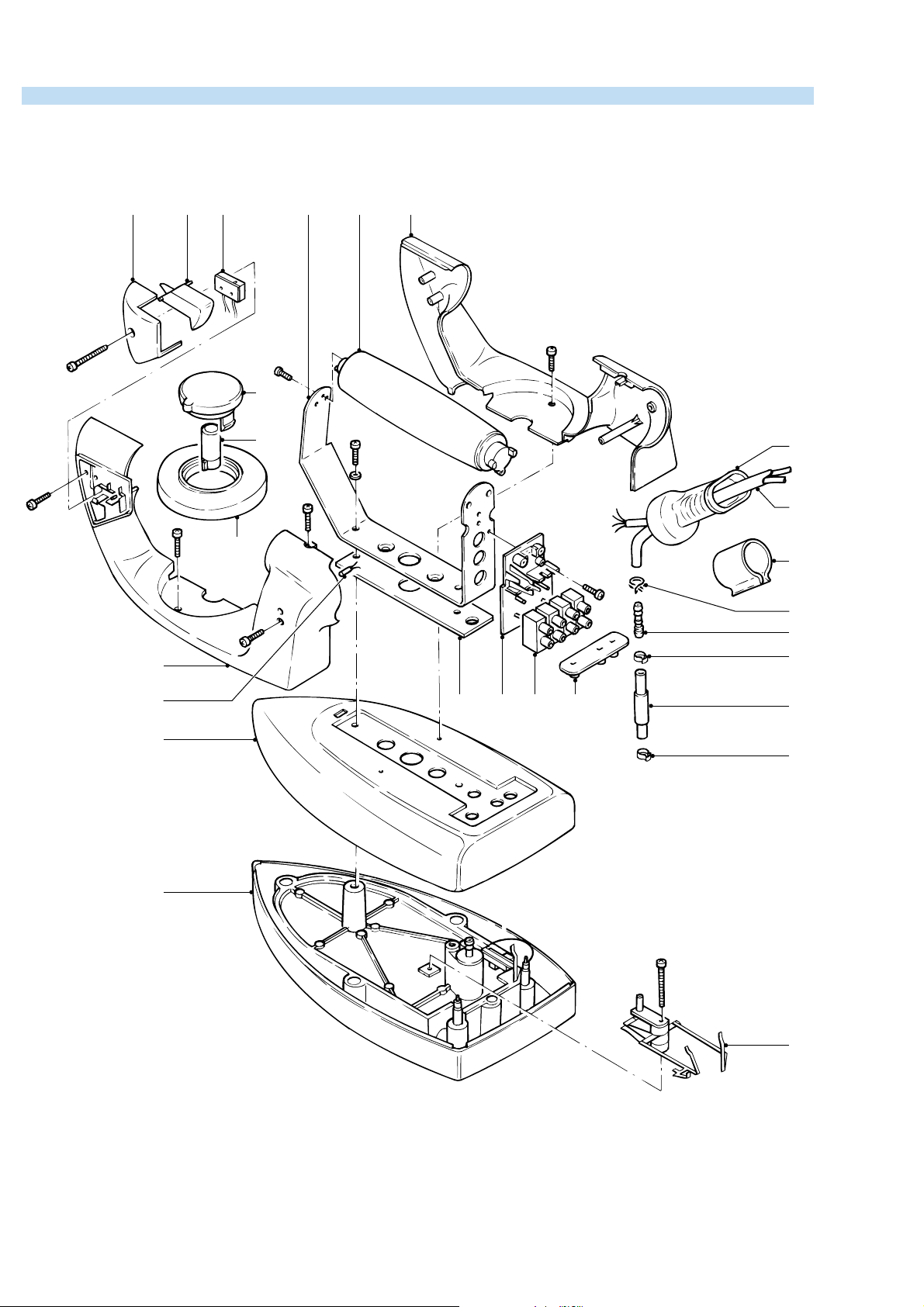
EXPLODED VIEW IRON
A
B
5
4 3 21 11
7
H
1
15
I
8
2x
X
D
9
E
2x
2
44
2x
F
12
C
6
24
13
10
16
18
Screws : d x 1
A 3.0 x 27
B 3.0 x 25
C 3.0 x 19
D 3.0 x 6
E 4.0 x 12
F 3.0 x 9
G M4 x 24
H 3.0 x 9
I M4 x 12
17232220
14
13
G
19
DAP1102
PCS 101 366
Page 3

PARTS LIST IRON DISASSEMBLY ADVISE IRON
Pos Description Service Nummer
Insert dial
6+7
10
11
12
13
14
15
16
17
18
19
20
21
1
Dial ring
2
Microswitch
3
Lever microswitch
4
Cover microswitch
5
Handle right + left part
Swivel, colour black
8
Steam hose / electric cable
9
Pilot light
Cork grip
Clamping ring
Clamping ring
Sleeve
Connecting bracket therm.
Metal cover
Insulating bracket
Sole plate + pos. 19
Thermostat
Insulating plate
Bracket + item 22 and 23
9965 000 02085
4822 532 12772
4822 282 30239
9965 000 02086
4822 442 00787
4822 310 10944
4822 325 10193
4822 530 10377
4822 134 10076
4822 498 10638
4822 492 71001
4822 532 12742
4822 325 10194
4822 402 10689
4822 442 00788
4822 466 11473
4822 259 10234
4822 282 30238
4822 466 11474
4822 310 10945
Hose joint24 4822 526 10669
TABLE UNIT
IRON
DIAL 1
RING 2
MICROSWITCH 3
LEVER
MICROSWITCH 4
remove SCREW A
remove COVER
MICROSWITCH 5
lift MICROSWITCH 3
unsolder WIRING
p
Dry
thermostat
Cut out
Cut
out
Steam-
valve
Steamswitch
Thermostat
Page 4

RON
REPLACE
HANDLE 6 + 7
remove SCREW B
remove SCREW C
remove SCREW D
remove SCREW E
D
E
B
REPLACE SWIVEL 8
REPLACE HOSE 9
REPLACE
PILOT LAMIP 10
disassemble HANDLE
PARTS 6+7
remove SCREW F 2 x
remove CONNECTING
WIRES
remove CLAMP( S )
REPLACE
CORK GRIP 11
disassemble HANDLE
PARTS 6+7
remove SCREW G
remove SCREW H
REPLACE COVER 16
REPLACE
SOLE PLATE 18
REPLACE
THERMOSTAT 19
REPLACE
INSULATING PLATE 20
C
remove DIAL 1
remove RING 2
remove HANDLE
PARTS 6+7
remove HOSE
remove SLEEVE
remove CORK GRIP
remove SCREW I
remove BRACKET 21
turn conductor B through
180 degrees
THERMOSTAT 19 ONLY
cut CONDUCTOR A
at location P
remove SCREW J
P
Q
B
A
D
ASSEMBLY
REQUIREMENTS
THERMOSTAT 19
Instead of metal conductor A,
the new thermostat has a wire
with AMP clamp.
After fi xing screw J, connect
the AMP clamp to tag Q.
After assembling cover 16
ALWAYS turn conductor B
through 180 degrees.
ADJUSTMENT AND CONTROLS
Thermostat 19
Thermostat ( 19 ) supplied as a spare part or fi tted to
the sole plate ( 18 ) has already been adjusted by the
supplier and secured by glue.
To avoid disfunction of the iron , NEVER readjust the
remove PLATE 17
thermostat.
NOTE :
For opening you need a Torx screwdriver 362 TR
T20 x 100.
PCS 101 367
Page 5

EXPLODED VIEW STAND
33
35
D
31
32
30
E
40
36
34
37
39
36
42
41
46
47
44
45
38
PCS 101 368
43
DAP1106
Page 6

PARTS LIST + DISASSEMBLY ADVICE STAND
Pos Description Service Nummer
Stand rubber feet
30
31
32
33
34
35
36
37
38
39
40
41
42
43
44
45
46
47
DFU
Rubber feet above screw
Complete tray
Safety valve
Rubber ring in fi lling hole
Cover
Rubber feet boiler
Boiler complete
Locked insert
Bottom housing
Filter
Switch
Electro valve
Cordset Italian plug
Cordset Europe plug
Steam dial
Steam regulator
Boiler empty lamp
Boiler ready lamp
GBR, FRA, DEU, NLD,
9965 000 01692
9965 000 01702
9965 000 01861
9965 000 01862
9965 000 01866
9965 000 01892
4822 462 71999
9965 000 01868
9965 000 01788
9965 000 01789
9965 000 01790
9965 000 01791
4822 218 11561
9965 000 01792
9965 000 01793
9965 000 01899
9965 000 01900
9965 000 01901
9965 000 01902
4222 001 92450
ESP, PRT, ITA
OPEN THE STAND
D
Below rubber feet
remove SCREW D (1 x)
E
E
remove SCREW E (3 x)
E
ADJUSTMENT AND CONTROLS
– To avoid leakage of the sealings and damage to
the components in and on the boiler, NEVER clean
the boiler with vinegar, a descaling agent or other
chemicals.
– The boiler doesn’t contain serviceable parts.
Never disassemble the boiler body and /or components on and in the boiler.
– ALWAYS REPLACE THE BOILER ( 37 ) WHEN:
the mechanical safety valve ( 33 ) has been acti-
*
vated.
the boiler thermostat or hand - resettable safety
*
thermostat are open, because the boiler has
been subjected to too high temperatures.
the electrovalve ( 42 ) fails or the sieve is soiled
*
with scale.
– After the product has been repaired, it should func-
tion properly and has to meet the safety requirements as laid down and offi cially established at this
moment.
remove LOCKED INSERT 38
NOTE:
OPEN NOW THE STAND.
DON’T WORRY IF THE SNAPS AT THE SIDE WILL BE
BROKEN.
THEY ARE ONLY FOR THE ASSEMBLY.
THE STAND REMAINS CLOSE WITHOUT THESE SNAPS.
 Loading...