

Page 1

Provapor vario elance
HI 914
Service
Information
!
Service
Information
!
Philips Domestic Appliances and Personal Care
Service
Information
!
Service Manual
SAP coding HI 914
PRODUCT INFORMATION
Feataures : inox sole plate
boiler capacity 1 litre
length steam hose 1,9 metre
length cord set 1,9 metre
maximum steam output 70 gr/min
steam ready indicator
boiler empty indicator
Voltage : 220-240 Volt
Frequency : 50-60 Hz
Power consumptium : Boiler : 1200 Watt
Pressure : 3 bar
Iron : 800 Watt
Product meets the requirements regarding interference
suppression on radio and television.
- After the product has been repaired, it should function
properly and has to meet the safety requirements as laid
down offi cially established at this moment.
Published by Philips Domestic Appliances and Personal Care Printed in the Netherlands © Copyright reserved Subject to modification
4322 277 00123
99/10
PCS 101 316
Page 2
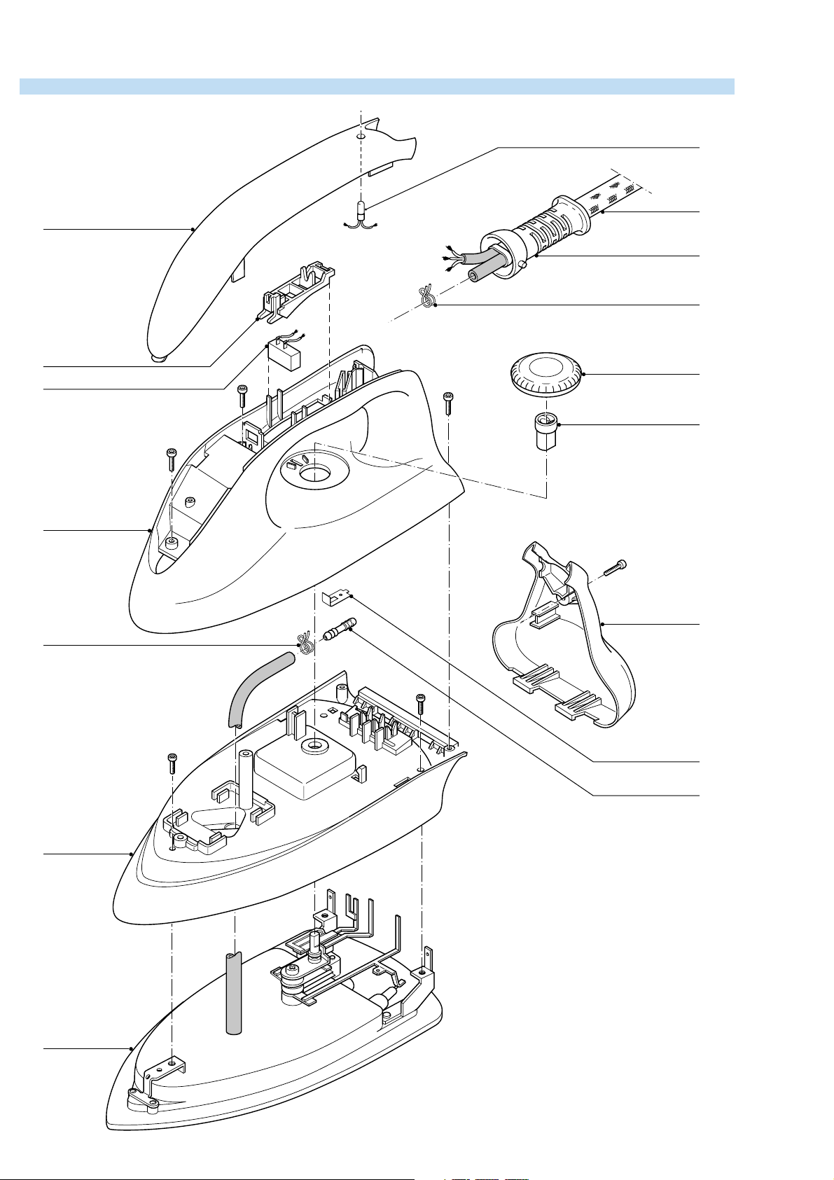
EXPLODED VIEW IRON
1
10
15
11
13
13
3
4
2
B
B
5
B
6
A
12
C
C
7
9
9
PCS 101 317
14
Screws : d x 1
A 3.5 x 12
B 3.5 x 14 (3x)
C M4 x 124 (3x)
DAP0996
Page 3

PARTS LIST IRON
Pos
10
11
12
13
14
15
Description Service Nummer
Inlay
1
Micro switch
2
Steam command lever
3
Therm. dial
4
Extention piece
5
Handle
6
Rattle
7
Skirt
8
Soleplate
9
Lamp
Ball swivel
Back plate
Thermostat
Spring clamp
Intermediate cable
9965 000 01887
9965 000 01888
9965 000 01680
9965 000 01681
9965 000 01682
9965 000 01683
4822 492 71445
9965 000 01684
9965 000 01685
9965 000 01686
9965 000 01687
9965 002 01689
9965 000 01690
4822 492 71001
9965 000 01691
TABLE UNIT IRON
Cut out
p
Steam-
Cut
out
valve
Dry
thermostat
Steamswitch
Thermostat
Page 4

DISASSEMBLY ADVISE IRON
BACK PLATE 12
remove SCREW A
INLAY 1
remove LAMP 10
remove MICRO SWITCH 2
HANDLE 6
remove THERM. DIAL 4
remove SCREW B (4x)
unlock HANDLE carefully
SKIRT 8
remove ELECTRICAL
WIRES
remove EXTENSION
PIECE 5
remove SPRING CLAMP
FROM STEAM HOSE
remove SCREW C (3x)
Bend back the contact points
THERMOSTAT 13
ONLY
cut CONDUCTOR A
at location P
remove SCREW D
P
Q
B
A
ASSEMBLY
REQUIREMENTS
THERMOSTAT 2
Instead of metal conductor A,
the new thermostat has a wire
with AMP clamp.
After fi xing screw D, connect
the AMP clamp to tag Q.
After assembling SKIRT 8
ALWAYS turn conductor B
through 180 degrees.
D
ADJUSTMENT AND CONTROLS
Thermostat 13
Thermostat ( 13 ) supplied as a spare part or fi tted to
the sole plate ( 9 ) has already been a djusted by the
supplier and secured by glue.
To avoid disfunction of the iron , NEVER readjust the
thermostat.
NOTE :
For opening you need a Torx screwdriver 362 TR
T20 x 100.
PCS 101 318
Page 5

EXPLODED VIEW STAND
24
26
D
22
23
21
E
31
27
25
28
30
27
33
32
38
39
36
37
29
PCS 101 319
34
DAP1000
Page 6

PARTS LIST + DISASSEMBLY ADVICE STAND
Pos
21
22
23
24
25
26
27
28
29
30
31
32
33
34
36
37
38
39
DFU
Description Service Nummer
Stand rubber feet
Rubber feet above screw
Complete tray
Safety cab
Rubber ring in fi lling hole
Cover
Rubber feet boiler
Boiler complete
Locked insert
Bottom housing
Filter
Switch
Electro valve
Cordset Italian plug
Cordset Europe plug
Steam dial
Steam regulator
Boiler empty lamp
Boiler ready lamp
GBR, FRA, DEU, NLD,
9965 000 01692
9965 000 01702
9965 000 01861
9965 000 01862
9965 000 01866
9965 000 01892
4822 462 71999
9965 000 01868
9965 000 01788
9965 000 01789
9965 000 01790
9965 000 01791
4822 218 11561
9965 000 01792
9965 000 01793
9965 000 01899
9965 000 01900
9965 000 01901
9965 000 01902
4222 001 92201
ESP, PRT, ITA
OPEN THE STAND
D
Below rubber feet
remove SCREW D (1 x)
E
E
remove SCREW E (3 x)
E
ADJUSTMENT AND CONTROLS
– To avoid leakage of the sealings and damage to the
components in and on the boiler, NEVER clean
the boiler with vinegar, a descaling agent or other
chemicals.
– The boiler doesn’t contain serviceable parts.
Never disassemble the boiler body and /or components on and in the boiler.
– ALWAYS REPLACE THE BOILER ( 28 ) WHEN:
the mechanical safety valve ( 24 ) has been
*
activated.
the boiler thermostat or hand - resettable
*
safety thermostat are open, because the boiler
has been subjected to too high temperatures.
the electrovalve ( 33 ) fails or the sieve is soiled
*
with scale.
– After the product has been repaired, it should
function properly and has to meet the safety
requirements as laid down and offi cially estab-
lished at this moment.
remove LOCKED INSERT 29
NOTE:
OPEN NOW THE STAND.
DON’T WORRY IF THE SNAPS AT THE SIDE WILL BE
BROKEN.
THEY ARE ONLY FOR THE ASSEMBLY.
THE STAND REMAINS CLOSE WITHOUT THESE SNAPS.
 Loading...