

Philips HI800, HI804, HD1809, HD1812 Service Manual
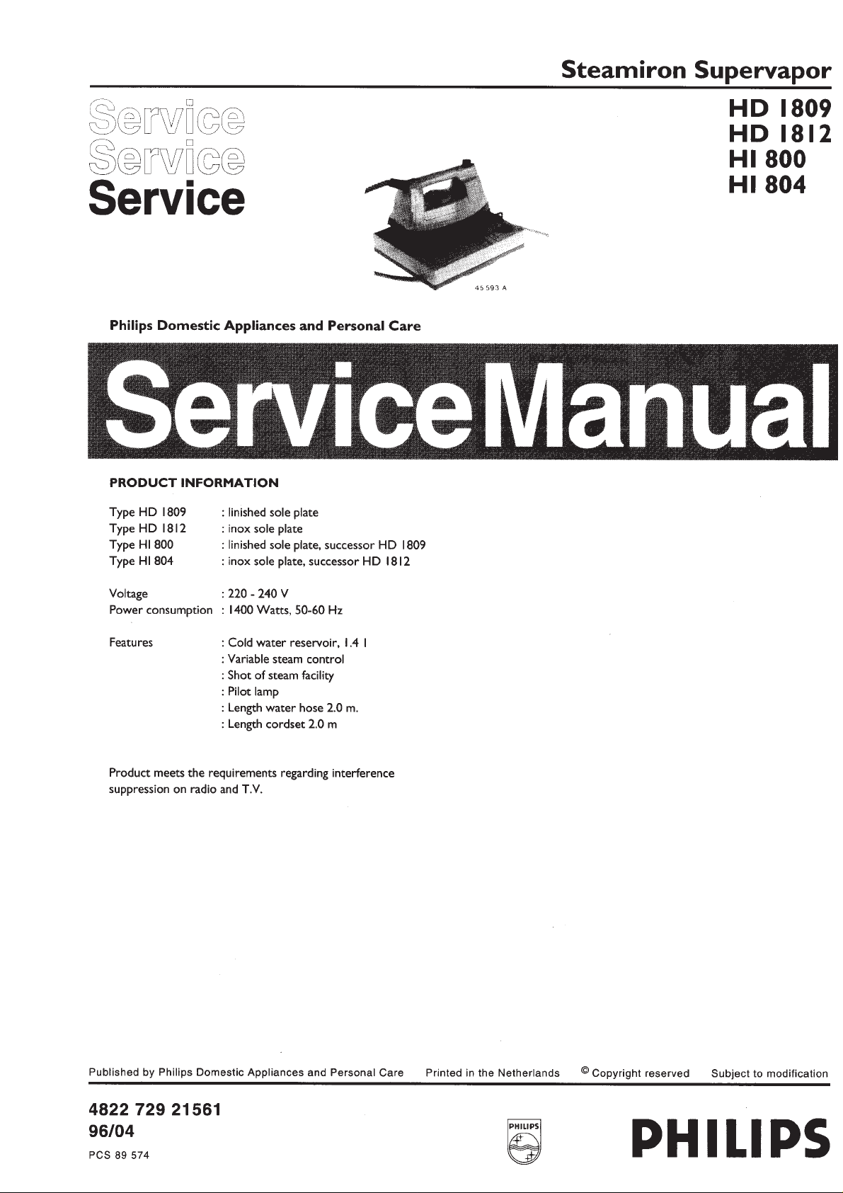
DISASSEMBLY ADVICE
DIAL 15
STEAM KNOB 3
NOSE COVER 7
PUMP 8
HOSE 14
HANDLE 6
remove STEAM KNOB 3
remove DIAL 15
remove SCREW A
remove NOSE 7
remove SCREW B
remove INLAY 1
remove SCREW C 2x
remove LAMP 17
unplug TERM. SOCKET 4.1
remove HOSE 11
remove TERM.SOCKET 4.2
remove HANDLE 6
remove NUT 9
remove PLATE 101
SOLE PLATE 10.1
SKIRT 10.2
THERMOSTAT 10.3
remove NOSE 7
remove SCREW B
remove SCREW A
remove INLAY 1
remove SCREW C
remove LAMP 17
unplug TERM.SOCKET 4.1
remove HOSE 11
remove TERM.SOCKET 4.2
remove HANDLE 6
remove THERM.BUSH 19
remove screw D 2x
(item 10.2 / 10.3 only)
INLAY 1
HOSE 11
SWIVEL 12
remove CAPS 20 4x
remove SCREW E 4x
remove HOUSING 33
remove screw G 2x
remove screw F
remove wiring / HOSE
remove SCREW A
remove INLAY 1
remove SCREW C 2x
remove LAMP 17
unplug TERM.SOCKET 4.1
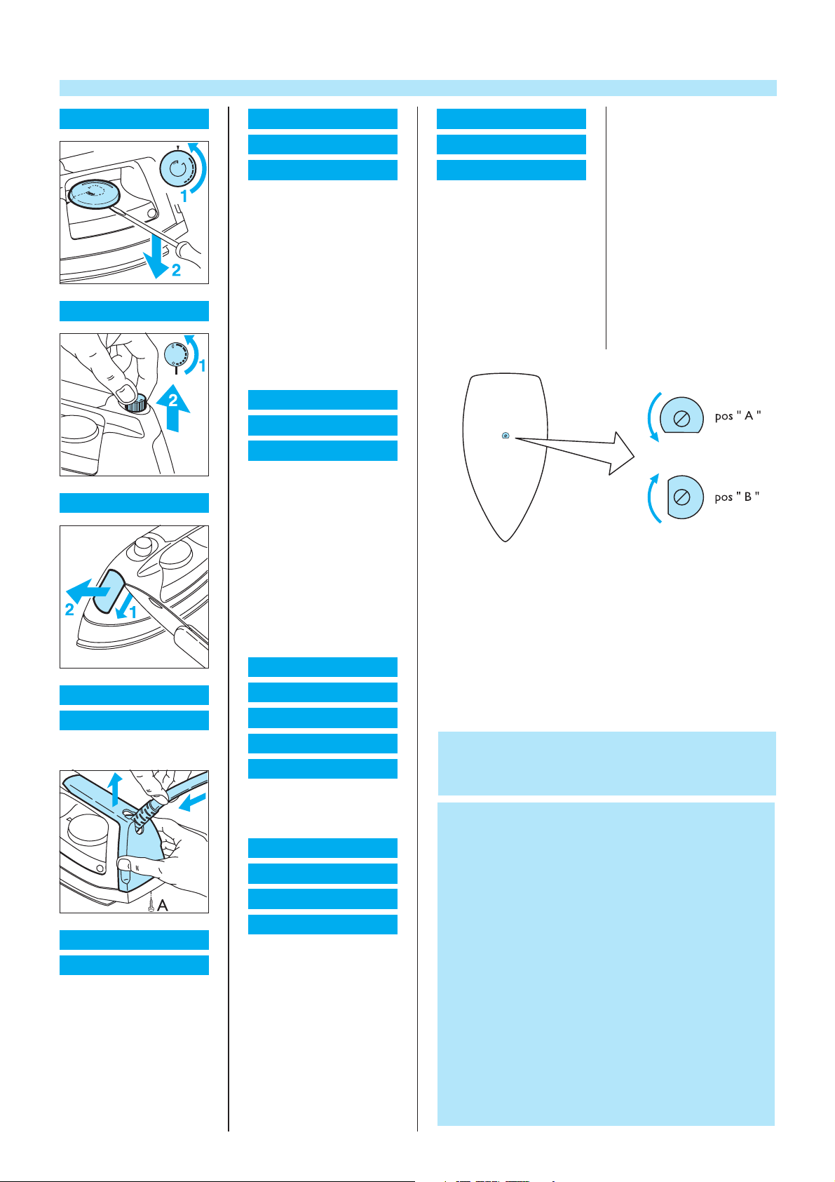
To adjust the thermostat.
The sole plate is completely cooled off.
Tum the bracket to position “A”
Then turn bracket a quarter turn clockwise to position “B”
You will hear a “ CLICK ”
Save the screw with loctite or the like
SWITCH 2
SWITCH KNOB 5
remove SCREW A
remove INLAY
LAMP 17
LAMP COVER 18
remove DIAL 15
remove SCREW A
remove NOSE 7
remove SCREW B
remove INLAY 1
remove SCREW C 2x
remove LAMP 17
unplug TERM.SOCKET 4.1
remove HOSE 11
remove TERM.SOCKET 4.2
remove HANDLE 6
PCS 89 575
CORDSET 24
SIEVE 26
SEALING RING 23
SEALING RING 25
SWITCH 22
remove CAP 20 4x
remove SCREW E 4x
remove HOUSING 33
SWITCH PLATE 29
SWITCH 30
PUMP 27
ONE WAY VALVE 28
remove CAP 20 4x
remove SCREW E 4x
remove HOUSING 33
remove SCREW F
remove wiring HOSE 11
remove wiring PUMP 27
remove wiring CORDSET 24
If in position “ B ” no “ CLICK ” is heard, adjust the thermostat with
the screw inside the thermostat shaft.
Turn the screw in such a way that a “ CLICK ” is heard in pos. “B”
Save the screw with loctite or the like.
N.B. This procedure is applicable if only the thermostat is
replaced.
Thermostats, see 10.1 have already been adjusted.
NOTES:
After the product has been repaired, it should function
properly and has to meet the safety requirements as laid
down and officially established at this moment.
N.B. Parts, with numbers from 100 upwards, cannot be
ordered separately.
Item 27 consists of one pump, a straight tube and a plug.
Products produced before week 9216 have 2 pumps.
If one of them needs to be replaced, proceed as follows :
- Remove 2 existing pumps and the T-connecting tube.
- Assemble the new pump and the corresponding straight
tube only.
The pump has to be assembled at the position indicated in
exploded view of this manual.
- Close the remaining hole in the water tank with the plug.
- Cut the 2 remaining electric connecting wires and insulate
the ends with insulation tape.
 Loading...