

Philips HI569 Service Manual
Steam Iron
HI569
Philips Domestic Appliances and Personal Care
Service Manual
PRODUCT INFORMATION
Features
- Pilot light
- Integrated cord winder
- Spray feature
- Variable steam (Max 30 g/min)
- Shot Of Steam, SOS (60 g/min)
- Vertical steam (60 g/min)
- Turbo steam (40 g/min)
- Self-clean function
- Anti-drip function
- Auto Shut Off, ASO
- Soft touch handle
- Cord length 2.4 m
- Anodilium soleplate
- Tank capacity 250 ml
- Carry case
Safety Information
- This product meets the requirements regarding interference
suppression on radio and TV.
- After the product has been repaired, it should function
properly and has to meet the safety requirements and legal
regulations as officially laid down at this moment.
Turbo steam function
The steam output of the variable steam function depends upon
the position of the slide knob.
When set to position 6 the steam output is 12 gr/min.
This might be not suffi cient. In that case the turbo button has to
be pushed down for max 10 sec. Due to this operation the steam
output will increase to 30 gr/min.
Vertical steam
When the iron is kept in a vertical position, the S.O.S. button
can be used to iron hanging fabrics as curtains.
Self-clean function
When the self-clean button is pushed down, a sudden fl ow of
water is released from the tank into the heated soleplate.
This thermal shock will cause scale particles come loose from the
steam chamber. These particles are then fl ushed out through the
steam vents by the water.
Anti-drip
Water is only released through the tank valve into the steam
chamber if the soleplate temperature is high enough to evaporate
all water. If the temperature is not hot enough, the tank valve is
closed by means of the bi-metal disc.
TECHNICAL INFORMATION
Voltage : 110 V, 220 V
Frequency : 50 - 60 Hz
Power Consumption : 110 V, 1100 W
220 V, 1650 W
Dimension (F-box) : 358 mm x 324 mm x 174 mm
Weight (Iron) : 1990 g
Weight (Carry case) : 710 g
Published by Philips Domestic Appliances and Personal Care Printed in the Netherlands © Copyright reserved Subject to modification
Auto shut-off
A relay in the electronic module interrupts the power to the
heating element when the iron has been motionless:
- for 30 seconds in horizontal position.
- for 8 minutes in vertical position.
03/12
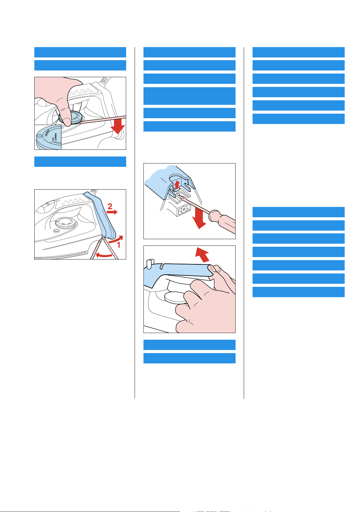
DISASSEMBLY ADVICE IRON
HI569
DIAL 1, 2, 3
RATTLE SPRING 5
BACK PLATE 4
remove SCREW C 1x
remove BACK PLATE 4
INLAY 6
OPERATION KNOBS 7
DOOR 8
DOOR HOLDER/
DEAIR. BUSH 9
SPRAY UNIT 10
ASO 11
remove SCREW C 1x
remove BACK PLATE 4
remove INLAY 6
HOUSING 15
SPRAY PUMP 16
S.O.S.PUMP 17
TANK 18
SELF CLEAN BUTTONS 19
SEALINGS 22
remove SCREW C 1x
remove BACK PLATE 4
remove INLAY 6
remove SCREW A 2x
remove DIAL 1, 2, 3
remove SCREWS cord clamping
remove SCREW B 3x
remove SCREW A1 2x
remove HOUSING 15
THERMOSTAT 20
THERMOSTAT PIN 21
SLIDE UNIT 12, 13
NEEDLE 14
remove SCREW C 1x
remove BACK PLATE 4
remove INLAY 6
remove SCREW A 2x
SEALINGS 22
COVER 25
TYPE PLATE 26
SOLEPLATE 23
ANTI-DRIP VALVE 24
remove SCREW C 1x
remove BACK PLATE 4
remove INLAY 6
remove SCREW A 2x
remove DIAL 1, 2, 3
remove SCREWS cord clamping
cord set
pilot light / pcb
remove SCREW B 3x
remove SCREW A1 2x
remove HOUSING 15
remove SCREW F 3x
2-7
REPAIR INSTRUCTIONS IRON
IMPORTANT
Due to the high wattage of the iron, only the specifi ed cordsets must be used.
NOTES :
1) For standardisation reasons :
Rattle spring : 5 pieces will be supplied when ordered.
Type plate : No info about the type number and voltage have been stamped onto the typeplate.
When replacing the type plate, engrave at least type number and voltage onto the typeplate with a
sharp object.
2) Parts, with numbers from 100 and higher, cannot be ordered separately.
3) After the product has been repaired, it should function properly and has to meet the safety requirements and legal regulations
as laid down and officially established at this moment.
ADJUSTMENT AND CONTROL
Thermostat :
Thermostat 20, fi tted to the soleplate 23 has already been adjusted by the supplier and secured by glue.
To avoid mal-function of the iron, NEVER re-adjust the thermostat.
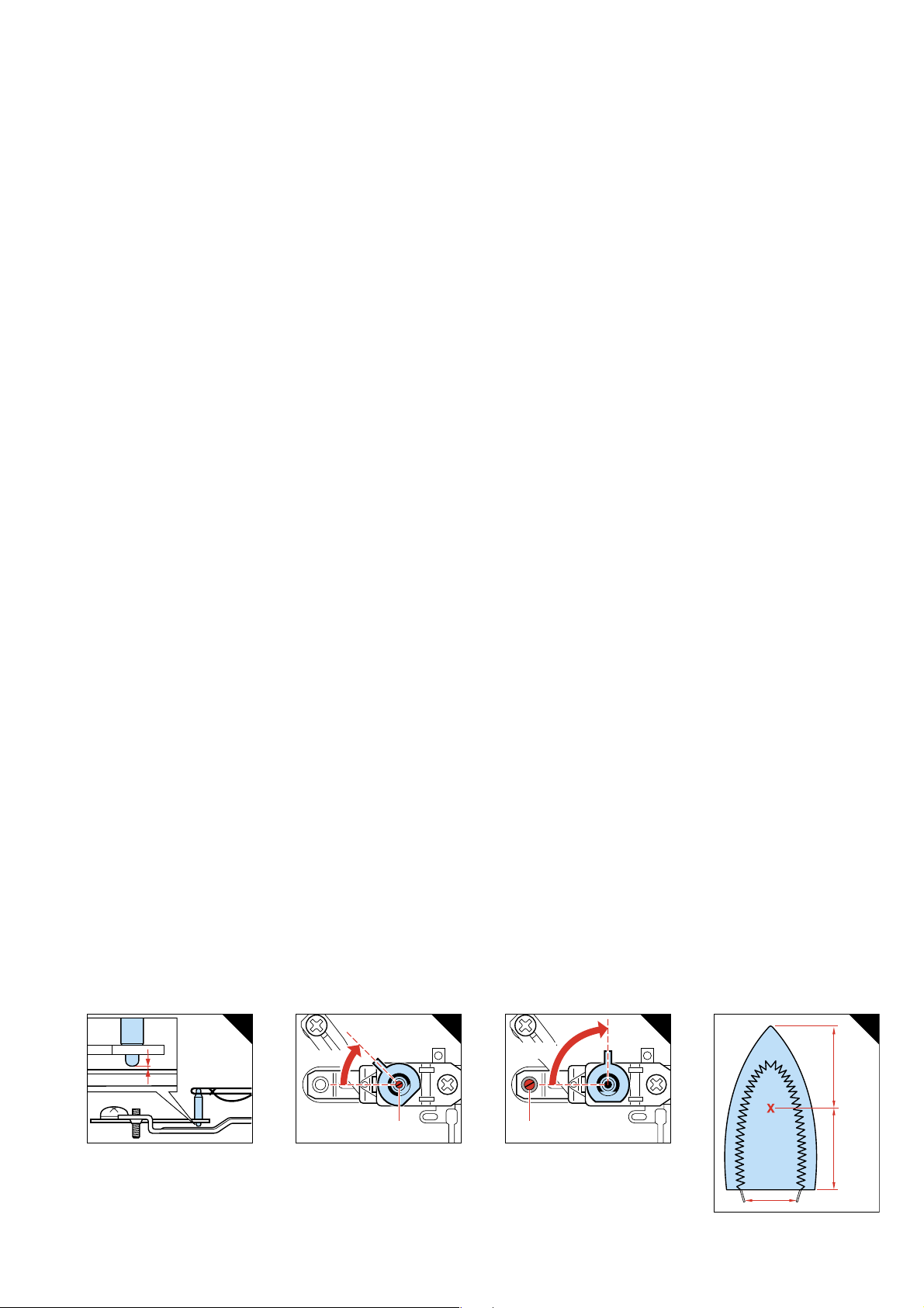
Adjustment thermostat 20, supplied as a spare part.
N.B. Before starting to adjust the thermostat, make sure that a gap exists between the lower tip of the ceramic insulating pin
and the real-off bracket. See fi g. 1.
HI569
Connect the connecting strips to an Ohm-meter.
Set the thermostat stopper to the position as indicated in fi g. 2.
Turn the adjusting screw R clockwise or anti-clockwise until the Ohm-meter indicates “0“. (The contacts closed)
Then turn the adjusting screw clockwise until the Ohm-meter indicates ∞ and the contacts have only just been opened.
You hear a “click”.
While loosely turning the thermostat stopper, check if the thermostat switches in the position as indicated in fi g. 2.
After the thermostat has been adjusted, adjust the real-off bracket.
Set the thermostat stopper in the position shown in fi g. 3.
The thermostat contacts are closed. (Ohm-meter indicates “0”)
Turn the set-screw S clockwise until the contacts have only just been opened.
The Ohm-meter indicates ∞.
Secure the adjusting screws with a glue.
After adjusting the thermostat, always check the temperature of the soleplate, with the dial set to MAX. position ( 215 ± 25 °C )
For location of testing point, see fi g. 4.
The temperature must be measured, after the iron has been connected to the mains for at least 15 min.
The max. temperature shall not be higher than 240 °C.
123
45˚-50
˚
RS
2
85˚-90
˚
4
==
Testpoint
3-7
 Loading...