

Philips HEF4520BD, HEF4520BU, HEF4520BT, HEF4520BPB, HEF4520BP Datasheet

DATA SH EET
Product specification
File under Integrated Circuits, IC04
January 1995
INTEGRATED CIRCUITS
HEF4520B
MSI
Dual binary counter
For a complete data sheet, please also download:
•The IC04 LOCMOS HE4000B Logic
Family Specifications HEF, HEC
•The IC04 LOCMOS HE4000B Logic
Package Outlines/Information HEF, HEC
January 1995 2
Philips Semiconductors Product specification
Dual binary counter
HEF4520B
MSI
DESCRIPTION
The HEF4520B is a dual 4-bit internally synchronous
binary counter. The counter has an active HIGH clock
input (CP0) and an active LOW clock input (CP1), buffered
outputs from all four bit positions (O0to O3) and an active
HIGH overriding asynchronous master reset input (MR).
The counter advances on either the LOW to HIGH
transition of the CP0input if CP1is HIGH or the HIGH to
LOW transition of the
CP1input if CP0 is low. Either CP0or
CP1may be used as the clock input to the counter and the
other clock input may be used as a clock enable input. A
HIGH on MR resets the counter (O0to O3= LOW)
independent of CP0, CP1.
Schmitt-trigger action in the clock input makes the circuit
highly tolerant to slower clock rise and fall times.
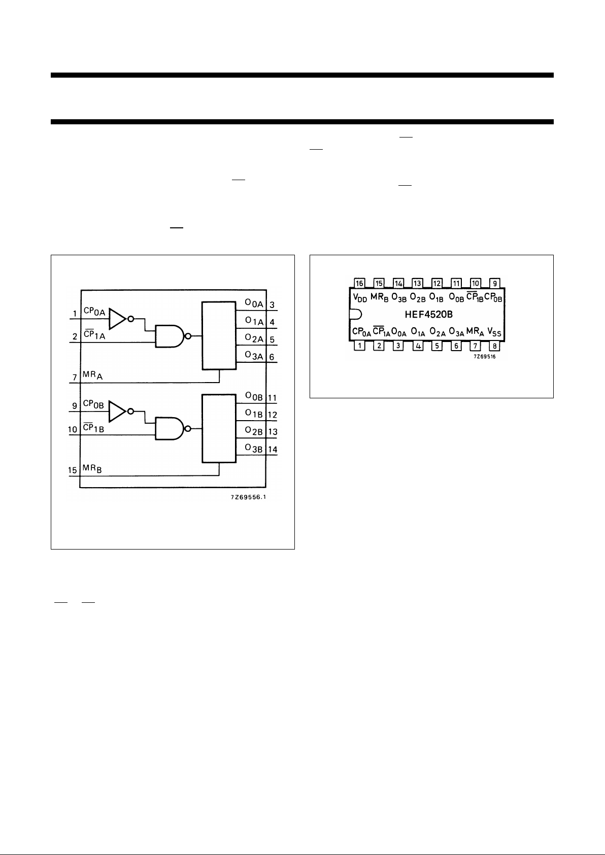
Fig.1 Functional diagram.
HEF4520BP(N): 16-lead DIL; plastic
(SOT38-1)
HEF4520BD(F): 16-lead DIL; ceramic (cerdip)
(SOT74)
HEF4520BT(D): 16-lead SO; plastic (SOT109-1)
(SOT109-1)
( ): Package Designator North America
Fig.2 Pinning diagram.
PINNING
FAMILY DATA, I
DD
LIMITS category MSI
See Family Specifications
CP
0A
,CP
0B
clock inputs (L to H triggered)
CP1A, CP
1B
clock inputs (H to L triggered)
MR
A
,MR
B
master reset inputs
O
0A
to O
3A
outputs
O
0B
to O
3B
outputs
January 1995 3
Philips Semiconductors Product specification
Dual binary counter
HEF4520B
MSI
This text is here in white to force landscape pages to be rotated correctly when browsing through the pdf in the Acrobat reader.This text is here in
_white to force landscape pages to be rotated correctly when browsing through the pdf in the Acrobat reader.This text is here inThis text is here in
white to force landscape pages to be rotated correctly when browsing through the pdf in the Acrobat reader. white to force landscape pages to be ...
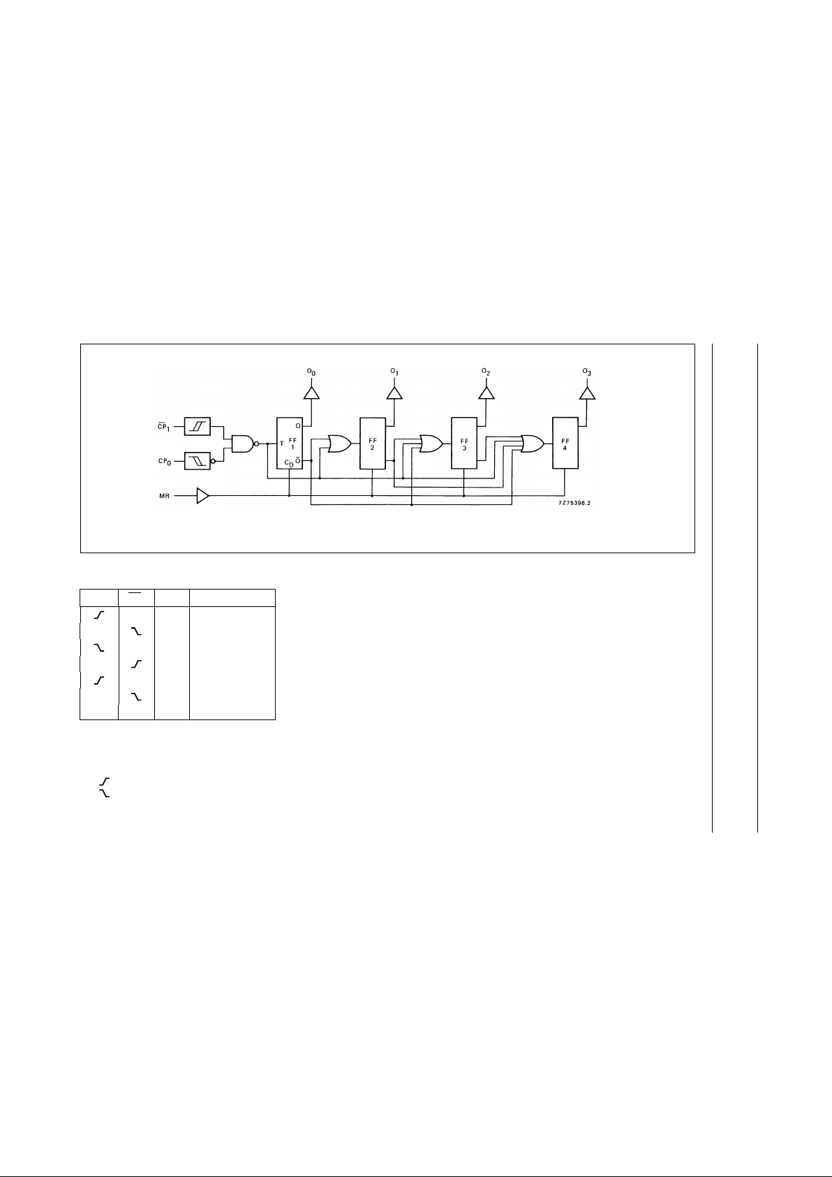
FUNCTION TABLE
Notes
1. H = HIGH state (the more positive voltage)
L = LOW state (the less positive voltage)
X = state is immaterial
= positive-going transition
= negative-going transition
CP
0
CP1MR MODE
H L counter advances
L L counter advances
X L no change
X L no change
L L no change
H L no change
XXHO
0
to O3= LOW
Fig.3 Logic diagram (one counter).
 Loading...